EP2277286B1 - Access point enhancements - Google Patents
Access point enhancements Download PDFInfo
- Publication number
- EP2277286B1 EP2277286B1 EP09830754.9A EP09830754A EP2277286B1 EP 2277286 B1 EP2277286 B1 EP 2277286B1 EP 09830754 A EP09830754 A EP 09830754A EP 2277286 B1 EP2277286 B1 EP 2277286B1
- Authority
- EP
- European Patent Office
- Prior art keywords
- access point
- station
- bss
- data
- sleep mode
- Prior art date
- Legal status (The legal status is an assumption and is not a legal conclusion. Google has not performed a legal analysis and makes no representation as to the accuracy of the status listed.)
- Active
Links
Images


Classifications
-
- H—ELECTRICITY
- H04—ELECTRIC COMMUNICATION TECHNIQUE
- H04W—WIRELESS COMMUNICATION NETWORKS
- H04W52/00—Power management, e.g. TPC [Transmission Power Control], power saving or power classes
- H04W52/02—Power saving arrangements
- H04W52/0209—Power saving arrangements in terminal devices
- H04W52/0225—Power saving arrangements in terminal devices using monitoring of external events, e.g. the presence of a signal
-
- H—ELECTRICITY
- H04—ELECTRIC COMMUNICATION TECHNIQUE
- H04W—WIRELESS COMMUNICATION NETWORKS
- H04W52/00—Power management, e.g. TPC [Transmission Power Control], power saving or power classes
- H04W52/02—Power saving arrangements
- H04W52/0203—Power saving arrangements in the radio access network or backbone network of wireless communication networks
- H04W52/0206—Power saving arrangements in the radio access network or backbone network of wireless communication networks in access points, e.g. base stations
-
- H—ELECTRICITY
- H04—ELECTRIC COMMUNICATION TECHNIQUE
- H04W—WIRELESS COMMUNICATION NETWORKS
- H04W52/00—Power management, e.g. TPC [Transmission Power Control], power saving or power classes
- H04W52/02—Power saving arrangements
- H04W52/0209—Power saving arrangements in terminal devices
- H04W52/0251—Power saving arrangements in terminal devices using monitoring of local events, e.g. events related to user activity
- H04W52/0258—Power saving arrangements in terminal devices using monitoring of local events, e.g. events related to user activity controlling an operation mode according to history or models of usage information, e.g. activity schedule or time of day
-
- H—ELECTRICITY
- H04—ELECTRIC COMMUNICATION TECHNIQUE
- H04W—WIRELESS COMMUNICATION NETWORKS
- H04W52/00—Power management, e.g. TPC [Transmission Power Control], power saving or power classes
- H04W52/02—Power saving arrangements
- H04W52/0209—Power saving arrangements in terminal devices
- H04W52/0261—Power saving arrangements in terminal devices managing power supply demand, e.g. depending on battery level
- H04W52/0287—Power saving arrangements in terminal devices managing power supply demand, e.g. depending on battery level changing the clock frequency of a controller in the equipment
- H04W52/029—Power saving arrangements in terminal devices managing power supply demand, e.g. depending on battery level changing the clock frequency of a controller in the equipment reducing the clock frequency of the controller
-
- H—ELECTRICITY
- H04—ELECTRIC COMMUNICATION TECHNIQUE
- H04W—WIRELESS COMMUNICATION NETWORKS
- H04W52/00—Power management, e.g. TPC [Transmission Power Control], power saving or power classes
- H04W52/02—Power saving arrangements
- H04W52/0209—Power saving arrangements in terminal devices
- H04W52/0261—Power saving arrangements in terminal devices managing power supply demand, e.g. depending on battery level
- H04W52/0287—Power saving arrangements in terminal devices managing power supply demand, e.g. depending on battery level changing the clock frequency of a controller in the equipment
-
- H—ELECTRICITY
- H04—ELECTRIC COMMUNICATION TECHNIQUE
- H04W—WIRELESS COMMUNICATION NETWORKS
- H04W84/00—Network topologies
- H04W84/02—Hierarchically pre-organised networks, e.g. paging networks, cellular networks, WLAN [Wireless Local Area Network] or WLL [Wireless Local Loop]
- H04W84/10—Small scale networks; Flat hierarchical networks
- H04W84/12—WLAN [Wireless Local Area Networks]
-
- H—ELECTRICITY
- H04—ELECTRIC COMMUNICATION TECHNIQUE
- H04W—WIRELESS COMMUNICATION NETWORKS
- H04W88/00—Devices specially adapted for wireless communication networks, e.g. terminals, base stations or access point devices
- H04W88/08—Access point devices
-
- Y—GENERAL TAGGING OF NEW TECHNOLOGICAL DEVELOPMENTS; GENERAL TAGGING OF CROSS-SECTIONAL TECHNOLOGIES SPANNING OVER SEVERAL SECTIONS OF THE IPC; TECHNICAL SUBJECTS COVERED BY FORMER USPC CROSS-REFERENCE ART COLLECTIONS [XRACs] AND DIGESTS
- Y02—TECHNOLOGIES OR APPLICATIONS FOR MITIGATION OR ADAPTATION AGAINST CLIMATE CHANGE
- Y02D—CLIMATE CHANGE MITIGATION TECHNOLOGIES IN INFORMATION AND COMMUNICATION TECHNOLOGIES [ICT], I.E. INFORMATION AND COMMUNICATION TECHNOLOGIES AIMING AT THE REDUCTION OF THEIR OWN ENERGY USE
- Y02D30/00—Reducing energy consumption in communication networks
- Y02D30/70—Reducing energy consumption in communication networks in wireless communication networks
Definitions
- This disclosure is directed to an access point, and more particularly to enhancing an access point to consume less power and/or require less memory.
- a wireless access point connects various wireless communication devices associated thereto to a wireless network, and relays data to and/or from the associated wireless communication devices.
- the wireless communication devices such as, for example, computers, printers, data storage, audio/video devices, and/or the like, may be connected to an access point directly or indirectly, and may exchange data with each other.
- the wireless access point is a very popular choice for implementing a home wireless network.
- Portable access points typically include an internal power source, such as, e.g., a rechargeable battery, to power the device when no external power source is available.
- EP-A 1 852 982 on which the preambles of the independent claims are based, US-A 2006/0268924 , US-B 7,415,262 , and US-A 2004/0229621 describe systems for dynamically adjusting the transmission power from a wireless access point in dependence on measured values of parameters indicative of operating conditions.
- BSS basic service set
- a method of operating an access point configured to connect a station to a wireless network includes monitoring one or more indicative parameters of a basic service set (BSS) which includes the access point and the station, and adjusting one or more operational parameters of the access point based on the one or more indicative parameters of the BSS.
- BSS basic service set
- a wireless network includes one or more basic service sets (BSS) connected to a distribution system.
- BSS basic service sets
- Each BSS includes one or more stations and an access point configured to connect the one or more stations to the wireless network.
- the access point includes a wired communication unit connected to the distribution system to receive data destined to the one or more stations, a data storage configured to buffer the data destined to the one or more stations, a wireless communication unit configured to send the data to the one or more stations, and a control unit configured to monitor one or more indicative parameters of the BSS and adjust one or more operational parameters of the access point based on the one or more indicative parameters of the BSS.
- the one or more indicative parameters of the BSS include at least one of an amount of data traffic flowing through the access point, proximity of the one or more stations to the access point, an activity level in the BSS, and a reaction of the one or more stations to a notification regarding the data buffered at the data storage of the access point.
- the one or more operational parameters of the access point include at least one of a clock frequency of the control unit, which is adjustable based on the amount of data traffic flowing through the access point, a transmit power of the wireless communication unit, which is adjustable based on the proximity of the one or more stations to the access point, an operational mode of the access point, which is switchable between an active mode and a sleep mode based on the activity level in the BSS, and an occupancy of the data storage, which is adjustable based on the reactions of the one or more stations regarding the data buffered at the data storage of the access point.
- the disclosure is directed to enhancing performances of an access point (AP), which is typically used to connect one or more stations associated thereto to a wireless network.
- the access point and associated remote stations may constitute a basic service set (BSS).
- the AP performance may be enhanced by monitoring one or more indicative parameters of the BSS and adjusting one or more operational AP parameters based on the one or more indicative BSS parameters.
- the indicative BSS parameters may include, for example, but are not limited to, an amount of data traffic flowing through the access point, proximity of the associated station to the access point, an activity level in the BSS, a reaction of the associated stations regarding data destined thereto and buffered at the access point, and/or the like.
- the operational AP parameters may include, for example, but are not limited to, a clock frequency of the access point, a transmit power of the access point, an operational mode of the access point, an occupancy of a buffer of the access point configured to buffer data destined to the associated station, and/or the like.
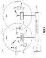
- FIG. 1 shows a configuration of a wireless local area network (WLAN) 100, constructed according to an embodiment of the disclosure.
- the WLAN 110 may include one or more basic service sets (BSS), such as, e.g., BSS 110 (BSS1), BSS 112 (BSS2) and/or the like.
- BSS 110 may include an access point 200 (AP1), a plurality of stations associated to the access point 200, such as, e.g., station 150 (S1), station 152 (S2), station 154 (S3), and/or the like.
- the access point 200 may connect the associated stations 150, 152, 154 to a wireless network within the BSS 110.
- the BSS 112 may include an access point 202 (AP2), one or more stations (e.g., a station 156 (S4)) associated to the access point 202 and/or the like.
- the access point 202 may connect the associated station 156 to a wireless network within the BSS 112.
- Certain stations, such as, the station 154 may be located in an area where the BSS 110 and BSS 112 overlap. In this case, the station 154 may be associated with either of the access points 200, 202 although FIG. 1 shows the station 154 associated with the access point 200.
- the access points 200, 202 may be connected to a distribution system 120, which may be a wired LAN or the like and configured to interconnect the access points, such as, e.g., the access points 200, 202, of the WLAN 100.
- the distribution system 120 may be connected to a server 130 or other networks, such as, e.g., the Internet (not shown), extranet (not shown) or the like.
- the distribution system 120 may allow any two or more stations, for example, the stations 150 and 156, connected to two different access points, for example, the access points 200, 202, to communicate with each other.
- the distribution system 120 may allow any station (such as, e.g., stations 150, 152, 154, or 156) within the WLAN 100 to communicate with other entities, such as, e.g., stations associated to other WLAN, LAN or the like, that may be connected to the WLAN 100.
- stations 150, 152, 154, or 156 within the WLAN 100 to communicate with other entities, such as, e.g., stations associated to other WLAN, LAN or the like, that may be connected to the WLAN 100.
- one or more of the access points 200, 202 may be configured with enhanced features, such as, e.g., reduced power consumption, reduced memory requirement and/or the like.
- FIG. 1 shows only the access point 200 being configured with one or more enhanced features, any number of the access points in the WLAN 100 may be configured with the enhancements.
- the access point 200 may be a portable access point configured with an internal power source (such as, e.g., a rechargeable battery, a solar cell array, or the like). By reducing power consumption, any portable access point (such as, e.g., the access points 200, 202) may substantially extend its battery life.
- the access point 200 may benefit from reduced power consumption due to the increasing environmental and economical constraints on energy consumption.
- the reduced memory requirement may also be advantageous because the access point 200 may be configured in a smaller housing or package, which may be particularly beneficial to portable access points.
- manufacturing costs may be reduced, since, e.g., less memory is needed.
- FIG. 2 shows a configuration of the access point 200 shown in FIG. 1 , constructed according to an embodiment of the disclosure.
- the access point 200 may include a control unit 210, a wireless communication unit 220, a wired communication unit 230, a data storage unit 240, a power supply unit 250 and/or the like.
- the control unit 210 may be configured to control an overall operation of the access point 200, including operations related to reducing power consumption and/or operations requiring less memory.
- the control unit 210 may include a power saving module 212 to operate the access point 200 with reduced power consumption.
- the control unit 210 may include a microprocessor, a microcontroller, or the like, which may be configured to execute instructions of a computer program stored in a machine readable storage medium.
- the instructions may include instructions for carrying out the power saving schemes.
- the control unit 210 may store the computer program embodying the instructions in its internal data storage (not shown), such as, e.g., an embedded read only memory (ROM), or the like, or, alternatively, in the data storage unit 240.
- ROM read only memory
- the wireless communication unit 220 may exchange data streams with the stations 150, 152, 154 (shown in FIG. 1 ) wirelessly via a specific radio frequency.
- the wired communication unit 230 may be connected to the distribution system 120 (shown in FIG. 1 ) and process data traffic between the access point 200 and the distribution system 120.
- the data storage unit 240 may temporarily store data that is sent to and from the associated stations 152, 154, 156.
- the data storage unit 240 may include a buffer 242 for buffering the data bound to the stations 152, 154, 156, as well as data bound to the access point 200 from the stations 152, 154, 156.
- the power supply unit 250 may be connected to the control unit 210, the wireless communication unit 220, the wired communication unit 230, the data storage unit 240 and/or the like, to supply power thereto.
- the power supply unit 250 may include a rechargeable battery, a non-rechargeable battery, an array of solar cells, a wired power supply configured to receive power from an external AC or DC power supply source, or the like.
- the operations related to reducing power consumption may include scaling a clock frequency of the control unit 210, adjusting transmit power of the wireless communication unit 220, efficiently activating a sleep mode, and/or the like.
- active periods of the access point 200 are typically interleaved with relatively longer inactive periods.
- substantial reduction in power consumption may be achieved by a clock frequency of the control unit 210 when the access point 200 is not active.
- the control unit 210 may operate at a lower clock frequency when no station is associated to the access point 200, none of the associated stations 150, 152, 154 is active, and/or the like.
- the access point 200 may be configured to adjust the clock frequency of the control unit 210 depending on a degree of the data traffic passing through the access point 200.
- the access point 200 may periodically determine an amount of data traffic flowing through the access point. Then, the access point 200 may lower the clock frequency of the control unit 210 when the amount of data traffic is reduced.
- the control unit 210 may be configured to dynamically scale the clock frequency to the amount of the data traffic.
- the control unit 210 may be provided with one or more threshold data traffic amount values and/or ranges and compare the amount of data traffic to the threshold values and/or ranges to determine an appropriate clock frequency for the amount of the data traffic.
- FIG. 3 shows a flow chart of a process 300 for adjusting a clock frequency of a controller (such as, e.g., the control unit 210 shown in FIG. 2 ) of an access point.
- the access point may start or initialize a counter for a predetermined period of time (e.g., 1 second) at step 312. Then, the access point may determine an amount of data traffic passing through the access point during the predetermined period of time at step 314. The determined amount of data traffic may be then compared to a first predetermined threshold value (e.g., 1000 bytes or 1 packet per second) at step 316.
- a first predetermined threshold value e.g. 1000 bytes or 1 packet per second
- the threshold value may be in terms of bytes, a number of packets and/or a combination of both bytes and a number of packets.
- the clock frequency of the controller may be lowered to a first clock frequency (e.g., 5 MHz), which may substantially reduce power consumption by the controller.
- more than one predetermined threshold value may be used. For example, when the amount of data traffic during the predetermined period of time is greater than the first predetermined threshold value at step 316, the amount of data traffic may be compared to a second predetermined threshold value (e.g., 100 Kbytes or 100 packets per second), which may be higher than the first predetermined threshold value, at step 330.
- a second predetermined threshold value e.g., 100 Kbytes or 100 packets per second
- the clock frequency of the controller may be lowered to a second clock frequency (e.g., 40 MHz) at step 334.
- the second clock frequency may be higher than the first clock frequency but lower than a normal clock frequency (e.g., 128 MHz) of the controller.
- the controller may maintain the normal clock frequency at step 332. Once the clock frequency of the controller is adjusted or maintained at steps 320, 332, 334, the access point may reset the counter at step 340, and the process may loop back to starting the counter at step 312. Alternatively, the process 300 may end.
- FIG. 3 shows only two predetermined threshold values for comparison with the amount of the data traffic passing through the access point, the number of threshold values might not be limited thereto and more than two threshold values may be used.
- the clock frequency of the controller may be adjusted proportionally to the amount of the data traffic passing through the access point.
- an access point may be configured to reduce the power consumption by adjusting transmit power. More specifically, the access point may adjust the transmit power depending on proximity (or distance) of stations associated thereto. For example, in FIG. 1 , when all the associated stations 150, 152, 154 are located close to the access point 200, the access point 200 may reduce the transmit power, which may reduce power consumption.
- FIG. 4 shows a flow chart of a process 400 for adjusting a transmit power of an access point, according to an embodiment of the disclosure.
- an access point may identify stations that are associated thereto at step 412. Then, the access point may determine proximity of the associated stations. For example, the access point may use transmit power control (TPC) algorithm, which is typically used to prevent undesirable interferences between two or more neighboring BSS's.
- TPC transmit power control
- the access point may measure a packet error rate (PER) of each associated station, as known in the art, at step 414. Based on the PER of each station, the access point may determine whether each station is within a predetermined range from the access point.
- PER packet error rate
- the access point may determine that all the associated stations are within a predetermined range and reduce the transmit power at step 420. Other methods may be used to determine whether the associated stations are within a predetermined range. When one or more associated stations are located outside the predetermined range at step 416, the access point may maintain the normal transmit power at step 418. Upon completing step 418 or step 420, the process 400 may terminate at step 430.
- a predetermined threshold value e.g. 10 %
- the process 400 may be repeated periodically to more aggressively attempt to reduce power consumption. Furthermore, more than one predetermined range may be used to more precisely scale the transmit power depending on proximity of the associated stations. Additionally, an inverse operation may be performed at steps 416 and 420. That is, if it is determined that all of the associated stations have moved away from the access point (step 416), beyond a predetermined range, then the transmit power may be increased by a predetermined value (step 420).
- Another effective way to reduce power consumption may be to effectively activate a sleep mode in an access point since an access point typically consumes a minimum amount of power during the sleep mode. However, it may be necessary to ensure that there is no active traffic in a BSS to which the access point belongs. This may be achieved in several different ways, including, for example, a clear-to-send (CTS) based sleep mode, a contention free period based sleep mode, a quiet period based sleep mode and/or the like.
- CTS clear-to-send
- an access point may send a CTS-to-self frame to prevent stations (such as, e.g.” the stations 150, 152, 154 in FIG. 1 ) associated thereto from sending any data to the access point. Then the access point may enter a sleep mode for a predetermined duration (i.e., sleep duration) specified in the CTS-to-self frame.
- the maximum sleep duration may be equal to a maximum duration that may be designated in the CTS-to-self frame, which may be, for example, about 32 ms.
- the access point may determine the actual sleep duration based on a level of activity in the BSS.
- the access point may keep track of a percentage of time that the access point is transmitting over the BSS, which is commonly referred to as medium occupancy, and may enter the sleep mode only for an amount of time when the BSS is expected to remain idle. This may be continuously adapted by tracking medium occupancy in the BSS periodically.
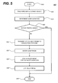
- FIG. 5 shows a flow chart of a process 500 for operating the CTS-based sleep mode in an access point, according to an embodiment of the disclosure.
- the access point may track medium occupancy of its BSS at step 512. Then, the access point may determine a sleep duration at step 514 based on the medium occupancy of the BSS obtained at step 512.
- the access point may take no action to enter the sleep mode and the process 500 may terminate at step 530.
- the access point may transmit a CTS-to-self frame to each of the associated stations at step 522.
- the CTS-to-self frame may include the sleep duration determined at step 514.
- the associated stations Upon receiving the CTS-to-self frame, the associated stations might not send data to the access point during the sleep duration specified in the CTS-to-self frame. Then, the access point may enter the sleep mode at step 524, and may stay in the sleep mode for the sleep duration at step 526. The access point may wake up when the sleep duration lapses at step 528, and the process 500 may terminate at step 530.
- a contention free period (CFP) based sleep mode operation may be used to operate the access point with reduced power consumption.
- the access point may advertise a contention free period in its beacons, which may prevent the associated stations from sending data traffic during the contention free period.
- the access point may safely enter and stay in the sleep mode during the contention free period. More specifically, an exact duration of the contention free period may be advertised in a MaxCFPDuration field in the beacon.
- the CFP based sleep mode operation may be executed based on the activities in the BSS, which may be similar to the CTS based sleep mode operation shown in FIG. 5 .
- the access point may also send quiet information element (IE) as part of a beacon to the associated stations in order to periodically silence the associated stations for a predetermined period of time before entering and staying in a sleep mode for a predetermined period of time.
- IE quiet information element
- the access point may send the CTS-to-self frame immediately after sending a delivery traffic indication message (DTIM) to ensure that the associated stations are not in the sleep mode and, hence, will receive the CTS-to-self frame.
- DTIM delivery traffic indication message
- FIG. 6 shows a flow chart of a process 600 for suspending the associated stations from sending data to an access point, according to an embodiment of the disclosure.
- the process 600 may be performed in connection with the process 500 shown in FIG. 5 .
- the access point may monitor activities in the BSS at step 620. If it is determined that there is active data traffic in the BSS at step 620, the process 600 may terminate at step 640. When it is determined that there is no active data traffic in the BSS at step 620, the access point may transit a DTIM beacon to the associated stations.
- the access point may, e.g., set a broadcast DTIM flag to 1 in the DTIM beacon to ensure that any associated stations in the sleep mode may stay awake to receive data that may be subsequently transmitted from the access point.
- the access point may transmit the CTS-to-self frame to the associated stations to ensure that the associated stations do not send any data to the access point during the sleep duration specified in the CTS-to-self frame.
- the access point may transmit a broadcast null data frame to the associated stations at step 626, in order to allow the associated stations to enter the sleep mode. To achieve this, the broadcast null data frame may be transmitted with the "more" data bit cleared.
- the access point may enter a sleep mode at step 628 and stay in the sleep mode for the remaining portion of the sleep duration specified in the CTS-to-self frame at step 630.
- the access point may wake up when the sleep duration has lapsed at step 632 and the process 600 may terminate at step 640.
- the access point may enter the sleep mode at most once per DTIM interval.
- the access point may take advantage of the process 600 to stay powered down for a maximum 90% of the total DTIM period, unless it is determined that there is active traffic in the BSS at step 620. Even with a commonly used beacon interval of 100 ms, the process 600 may achieve, e.g., about 30% power savings.
- the CTS-based sleep mode operation shown in FIG. 5 may cause undesirable interference on an overlapping or neighboring BSS.
- the CTS-based sleep mode operation performed in the BSS 110 may interfere with operations of the BSS 112. More specifically, upon receiving the CTS-to-self frame from the access point 200 of the BSS 110, the access point 202 and/or the station 156 in the BSS 112 may also stop sending data during the sleep duration in the CTS-to-self frame.
- it may be necessary to reduce or minimize the interference on an overlapping or neighboring BSS. This may be achieved by transmitting the CTS-to-self frame at an optimal transmit power, which may be strong enough to reach all the associated stations but not strong enough to reach an access point and/or stations in an overlapping or neighboring BSS.
- an access point may sequentially transmit request-to-send (RTS) frames at gradually increased transmit power levels, preferably starting from a lowest transmit power level, until the access point successfully receives responses from all the stations associated thereto.
- the RTS frame indicates that the access point is ready to send data.
- the access point may transmit a CTS-to-self frame at the power level the RTS frames were transmitted when all the associated stations have responded.
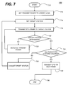
- FIG. 7 shows a flow chart of a process 700 for reducing an impact on another basic service set (BSS) when an access point operates the CTS-based sleep mode, according to an embodiment of the disclosure.
- the access point may set its transmit power to the lowest level (e.g., 5 dBm) at step 712. Then, the access point may set one of stations associated thereto as a target station, and transmit an RTS frame to the target station at the lowest power level at step 716.
- the access point may slightly increase the transmit power level at step 722 and the process 700 may loop back to transmitting the RTS frame to the target station at the increased transmit power at step 716.
- the access point may determine whether all of the associated stations have been checked as the target station at step 730. When it is determined that one or more associated stations have not been checked at step 730, the access point may change the target station to one of the stations that have not been checked at step 732, and the process 700 may move to set another station as the new target station 714. These steps (e.g., steps 714, 716, 720, 722, 730, 732) may be repeated until the access point receives responses to the RTS frame from all the associated stations. As a result, the transmit power may be increased to an optimum power level at which the RTS frame has been transmitted when all the associated stations have responded thereto.
- steps 714, 716, 720, 722, 730, 732 may be repeated until the access point receives responses to the RTS frame from all the associated stations.
- the access point may transmit a CTS-to-self frame at the optimum power level at step 740. This may ensure that the CTS-to-self frame may reach all of the associated stations while preventing the CTS-to-self frame from reaching further than the most distant associated station. For example, in FIG. 1 , the access point 200 may transmit the CTS-to-self frame at a sufficient power level to reach all of the associated stations 150, 152, 154, but not sufficient to reach the access point 202 or the station 156 in the BSS 112. Upon transmitting the CTS-to-self frame at the optimized power level at step 740, the process may terminate at step 750.
- an access point may need to leave sufficient available medium time for other devices (such as, e.g., an access point, a station and/or the like) in an overlapping BSS when the devices are within a communication range from the access point.
- the access point may determine the medium occupancies of the BSSs as respective percentages of the total available medium time. Then, the access point may not stay in a sleep mode longer than the idle time available on the radio frequency channel. For example, when the current medium occupancy of the BSS is 75%, the access point of the BSS may not stay in the sleep mode longer than 25% of the beacon interval.
- an access point may include a smaller memory in order to reduce a physical size and manufacturing costs thereof, which may be particularly advantageous for a portable access point.
- an access point rarely sends data to an associated station in a sleep mode because, if there is incoming data traffic, the station may stay awake until processing of the incoming data traffic is completed. If the station stays in a sleep mode and does not process the incoming data traffic, it may mean that the incoming data traffic may not be important to the station and may no longer need to be buffered.
- the access point may reserve a smaller buffer (for example, 2 Kbytes) for each associated station in the sleep mode and may drop excess data traffic when the buffer overflows.
- FIG. 8 shows a flow chart of a process 800 for operating an access point to process unicast data traffic for a destination station associated thereto, according to an embodiment of the disclosure.
- the access point may receive unicast data traffic destined for the destination station at step 812. If the destination station is not in a sleep mode at step 814, the process 800 may terminate at step 840. If the destination station is in a sleep mode at step 814, the access point may buffer the unicast data at step 816 and notify the destination station of the incoming data therefor at step 818. For example, the access point may transmit a DTIM beacon to the destination station to notify the station of the incoming data traffic.
- the buffered data may be sent to the destination station at step 822 and the process 800 may terminate at step 840.
- the destination station reacts negatively (e.g., responding with an instruction not to send the buffered data) or the destination station does not respond (react) to the notification at step 820 (e.g., staying in the sleep mode) and the buffer overflows with the unicast data at step 830, the access point may drop the excess unicast data at step 832.
- the station may react negatively or not respond to the notification at step 820 where, for example, the unicast data may not be important to the destination station.
- the access point may keep buffering the unicast data and the process 800 may terminate at step 840. Accordingly, by configuring the access point to drop the excess unicast data in the destination buffer when the buffer overflows, the access point may operate normally with a smaller buffer with reduced storage capacity.
- an access point may buffer all multicast data traffic if any of the destination stations associated thereto is in a sleep mode.
- the multicast data may be delivered to the destination stations after the access point transmits a DTIM beacon.
- the multicast data may be typically used for non-active situations (e.g., service advertisement, discovery and/or the like).
- non-active situations e.g., service advertisement, discovery and/or the like.
- an active service or agent may generate multicast frames less frequently than once every few seconds.
- the access point may be configured to adjust a number of buffers reserved for each destination station depending on a situation, such as, e.g., the active situations, the non-active situation and the like. Particularly, the access point may reserve a smaller number of buffers (e.g., five to ten buffers) for buffering the multicast data for the non-active situations.
- the multicast data frames for the non-active situations may be typically much shorter than the maximum frame length.
- the access point may be configured to adjust the buffer size in order to reduce the overall memory requirement.
- the access point may store the non-active multicast data frames in, e.g., without limitation, a contiguous FIFO or the like.
- the access point may be further configured to buffer overflow multicast data traffic in host memory when all the reserved buffers in device memory become entirely occupied before the DTIM beacon arrives. This may be achieved by, for example, a token passing mechanism between the host and the device.
- the device may send tokens to the host when the buffers reserved for multicast data traffic during the sleep mode become free.
- the host may deduct tokens when it sends multicast data frames to the device.
- the host may limit the multicast data traffic sent to the associated station based upon the number of tokens it currently possesses.
Description
- This disclosure is directed to an access point, and more particularly to enhancing an access point to consume less power and/or require less memory.
- A wireless access point connects various wireless communication devices associated thereto to a wireless network, and relays data to and/or from the associated wireless communication devices. For example, the wireless communication devices, such as, for example, computers, printers, data storage, audio/video devices, and/or the like, may be connected to an access point directly or indirectly, and may exchange data with each other. Thus, the wireless access point is a very popular choice for implementing a home wireless network. Currently, many of the wireless access points on the market are stationary access points, which require an external source and, hence, might not be used when no power source is available. Portable access points typically include an internal power source, such as, e.g., a rechargeable battery, to power the device when no external power source is available.
-
EP-A 1 852 982 , on which the preambles of the independent claims are based,US-A 2006/0268924 ,US-B 7,415,262 , andUS-A 2004/0229621 describe systems for dynamically adjusting the transmission power from a wireless access point in dependence on measured values of parameters indicative of operating conditions. - In one aspect of the disclosure, an access point configured to connect a station to a wireless network includes a wireless communication unit configured to send data to the station, and a control unit configured to adjust one or more operational parameters of the access point based on indicative parameters of a basic service set (BSS).
- According to another aspect of the disclosure, a method of operating an access point configured to connect a station to a wireless network includes monitoring one or more indicative parameters of a basic service set (BSS) which includes the access point and the station, and adjusting one or more operational parameters of the access point based on the one or more indicative parameters of the BSS.
- In yet another aspect of the disclosure, a wireless network includes one or more basic service sets (BSS) connected to a distribution system. Each BSS includes one or more stations and an access point configured to connect the one or more stations to the wireless network. The access point includes a wired communication unit connected to the distribution system to receive data destined to the one or more stations, a data storage configured to buffer the data destined to the one or more stations, a wireless communication unit configured to send the data to the one or more stations, and a control unit configured to monitor one or more indicative parameters of the BSS and adjust one or more operational parameters of the access point based on the one or more indicative parameters of the BSS. The one or more indicative parameters of the BSS include at least one of an amount of data traffic flowing through the access point, proximity of the one or more stations to the access point, an activity level in the BSS, and a reaction of the one or more stations to a notification regarding the data buffered at the data storage of the access point. The one or more operational parameters of the access point include at least one of a clock frequency of the control unit, which is adjustable based on the amount of data traffic flowing through the access point, a transmit power of the wireless communication unit, which is adjustable based on the proximity of the one or more stations to the access point, an operational mode of the access point, which is switchable between an active mode and a sleep mode based on the activity level in the BSS, and an occupancy of the data storage, which is adjustable based on the reactions of the one or more stations regarding the data buffered at the data storage of the access point.
- Additional features, advantages, and embodiments of the disclosure may be set forth or apparent from consideration of the following detailed description, drawings, and claims. Moreover, it is to be understood that both the foregoing summary of the disclosure and the following detailed description are exemplary and intended to provide further explanation without limiting the scope of the disclosure as claimed.
- The accompanying drawings, which are included to provide a further understanding of the disclosure, are incorporated in and constitute a part of this specification, illustrate embodiments of the disclosure and together with the detailed description serve to explain the principles of the disclosure. No attempt is made to show structural details of the disclosure in more detail than may be necessary for a fundamental understanding of the disclosure and the various ways in which it may be practiced. In the drawings:
-
FIG. 1 shows a wireless local area network (WLAN) configuration employing an access point, constructed according to an embodiment of the disclosure; -
FIG. 2 shows an example of a configuration of the access point shown inFIG. 1 , constructed according to an embodiment of the disclosure; -
FIG. 3 shows a flow chart of a process for adjusting a clock frequency of a controller of an access point, within an embodiment of the disclosure; -
FIG. 4 shows a flow chart of a process for adjusting a transmit power of an access point, according to an embodiment of the disclosure; -
FIG. 5 shows a flow chart of a process for activating a sleep mode in an access point, according to an embodiment of the disclosure; -
FIG. 6 shows a flow chart of a process for suspending an associated station from sending data traffic to an access point in a sleep mode, according to an embodiment of the disclosure; -
FIG. 7 shows a flow chart of a process for reducing an impact on another basic service set (BSS) when an access point suspends an associated station from sending data traffic, according to an embodiment of the disclosure; and -
FIG. 8 shows a flow chart of a process for operating an access point to handle unicast data traffic, according to an embodiment of the disclosure. - The embodiments of the disclosure and the various features and advantageous details thereof are explained more fully with reference to the non-limiting embodiments and examples that are described and/or illustrated in the accompanying drawings and detailed in the following description. It should be noted that the features illustrated in the drawings are not necessarily drawn to scale, and features of one embodiment may be employed with other embodiments as the skilled artisan would recognize, even if not explicitly stated herein. Descriptions of well-known components and processing techniques may be omitted so as to not unnecessarily obscure the embodiments of the disclosure. The examples used herein are intended merely to facilitate an understanding of ways in which the disclosure may be practiced and to further enable those of skill in the art to practice the embodiments of the disclosure. Accordingly, the examples and embodiments herein should not be construed as limiting the scope of the disclosure, which is defined solely by the appended claims and applicable law. Moreover, it is noted that like reference numerals represent similar parts throughout the several views of the drawings.
- The disclosure is directed to enhancing performances of an access point (AP), which is typically used to connect one or more stations associated thereto to a wireless network. The access point and associated remote stations may constitute a basic service set (BSS). The AP performance may be enhanced by monitoring one or more indicative parameters of the BSS and adjusting one or more operational AP parameters based on the one or more indicative BSS parameters. The indicative BSS parameters may include, for example, but are not limited to, an amount of data traffic flowing through the access point, proximity of the associated station to the access point, an activity level in the BSS, a reaction of the associated stations regarding data destined thereto and buffered at the access point, and/or the like. The operational AP parameters may include, for example, but are not limited to, a clock frequency of the access point, a transmit power of the access point, an operational mode of the access point, an occupancy of a buffer of the access point configured to buffer data destined to the associated station, and/or the like.
-
FIG. 1 shows a configuration of a wireless local area network (WLAN) 100, constructed according to an embodiment of the disclosure. The WLAN 110 may include one or more basic service sets (BSS), such as, e.g., BSS 110 (BSS1), BSS 112 (BSS2) and/or the like. The BSS 110 may include an access point 200 (AP1), a plurality of stations associated to theaccess point 200, such as, e.g., station 150 (S1), station 152 (S2), station 154 (S3), and/or the like. Theaccess point 200 may connect theassociated stations access point 202 and/or the like. Theaccess point 202 may connect theassociated station 156 to a wireless network within theBSS 112. Certain stations, such as, thestation 154 may be located in an area where the BSS 110 and BSS 112 overlap. In this case, thestation 154 may be associated with either of theaccess points FIG. 1 shows thestation 154 associated with theaccess point 200. - The
access points distribution system 120, which may be a wired LAN or the like and configured to interconnect the access points, such as, e.g., theaccess points WLAN 100. Thedistribution system 120 may be connected to aserver 130 or other networks, such as, e.g., the Internet (not shown), extranet (not shown) or the like. Thedistribution system 120 may allow any two or more stations, for example, thestations access points distribution system 120 may allow any station (such as, e.g.,stations WLAN 100. - In the WLAN 100, one or more of the
access points FIG. 1 shows only theaccess point 200 being configured with one or more enhanced features, any number of the access points in theWLAN 100 may be configured with the enhancements. Theaccess point 200 may be a portable access point configured with an internal power source (such as, e.g., a rechargeable battery, a solar cell array, or the like). By reducing power consumption, any portable access point (such as, e.g., theaccess points 200, 202) may substantially extend its battery life. Even if theaccess point 200 is stationary and connected to a power source, theaccess point 200 may benefit from reduced power consumption due to the increasing environmental and economical constraints on energy consumption. The reduced memory requirement may also be advantageous because theaccess point 200 may be configured in a smaller housing or package, which may be particularly beneficial to portable access points. Furthermore, manufacturing costs may be reduced, since, e.g., less memory is needed. -
FIG. 2 shows a configuration of theaccess point 200 shown inFIG. 1 , constructed according to an embodiment of the disclosure. Theaccess point 200 may include acontrol unit 210, awireless communication unit 220, awired communication unit 230, adata storage unit 240, apower supply unit 250 and/or the like. Thecontrol unit 210 may be configured to control an overall operation of theaccess point 200, including operations related to reducing power consumption and/or operations requiring less memory. For example, thecontrol unit 210 may include apower saving module 212 to operate theaccess point 200 with reduced power consumption. Thecontrol unit 210 may include a microprocessor, a microcontroller, or the like, which may be configured to execute instructions of a computer program stored in a machine readable storage medium. The instructions may include instructions for carrying out the power saving schemes. Thecontrol unit 210 may store the computer program embodying the instructions in its internal data storage (not shown), such as, e.g., an embedded read only memory (ROM), or the like, or, alternatively, in thedata storage unit 240. - The
wireless communication unit 220, which may include anantenna 222, may exchange data streams with thestations FIG. 1 ) wirelessly via a specific radio frequency. Thewired communication unit 230 may be connected to the distribution system 120 (shown inFIG. 1 ) and process data traffic between theaccess point 200 and thedistribution system 120. Thedata storage unit 240 may temporarily store data that is sent to and from the associatedstations data storage unit 240 may include abuffer 242 for buffering the data bound to thestations access point 200 from thestations power supply unit 250 may be connected to thecontrol unit 210, thewireless communication unit 220, the wiredcommunication unit 230, thedata storage unit 240 and/or the like, to supply power thereto. Thepower supply unit 250 may include a rechargeable battery, a non-rechargeable battery, an array of solar cells, a wired power supply configured to receive power from an external AC or DC power supply source, or the like. - The operations related to reducing power consumption may include scaling a clock frequency of the
control unit 210, adjusting transmit power of thewireless communication unit 220, efficiently activating a sleep mode, and/or the like. Regarding the clock frequency scaling, active periods of theaccess point 200 are typically interleaved with relatively longer inactive periods. Thus, substantial reduction in power consumption may be achieved by a clock frequency of thecontrol unit 210 when theaccess point 200 is not active. For example, thecontrol unit 210 may operate at a lower clock frequency when no station is associated to theaccess point 200, none of the associatedstations access point 200 may be configured to adjust the clock frequency of thecontrol unit 210 depending on a degree of the data traffic passing through theaccess point 200. Theaccess point 200 may periodically determine an amount of data traffic flowing through the access point. Then, theaccess point 200 may lower the clock frequency of thecontrol unit 210 when the amount of data traffic is reduced. In an embodiment, thecontrol unit 210 may be configured to dynamically scale the clock frequency to the amount of the data traffic. Alternatively, thecontrol unit 210 may be provided with one or more threshold data traffic amount values and/or ranges and compare the amount of data traffic to the threshold values and/or ranges to determine an appropriate clock frequency for the amount of the data traffic. - For example,
FIG. 3 shows a flow chart of aprocess 300 for adjusting a clock frequency of a controller (such as, e.g., thecontrol unit 210 shown inFIG. 2 ) of an access point.
Upon starting the process atstep 310, the access point may start or initialize a counter for a predetermined period of time (e.g., 1 second) atstep 312. Then, the access point may determine an amount of data traffic passing through the access point during the predetermined period of time atstep 314. The determined amount of data traffic may be then compared to a first predetermined threshold value (e.g., 1000 bytes or 1 packet per second) atstep 316. The threshold value may be in terms of bytes, a number of packets and/or a combination of both bytes and a number of packets. When the amount of data traffic during the predetermined period of time is smaller than the first predetermined threshold value atstep 316, the clock frequency of the controller may be lowered to a first clock frequency (e.g., 5 MHz), which may substantially reduce power consumption by the controller. - For more precise scaling of the clock frequency, more than one predetermined threshold value may be used. For example, when the amount of data traffic during the predetermined period of time is greater than the first predetermined threshold value at
step 316, the amount of data traffic may be compared to a second predetermined threshold value (e.g., 100 Kbytes or 100 packets per second), which may be higher than the first predetermined threshold value, atstep 330. When the amount of data traffic is smaller than the second predetermined threshold value atstep 330, the clock frequency of the controller may be lowered to a second clock frequency (e.g., 40 MHz) atstep 334. The second clock frequency may be higher than the first clock frequency but lower than a normal clock frequency (e.g., 128 MHz) of the controller. When the amount of data traffic is greater than the second predetermined threshold value, the controller may maintain the normal clock frequency atstep 332. Once the clock frequency of the controller is adjusted or maintained atsteps step 340, and the process may loop back to starting the counter atstep 312. Alternatively, theprocess 300 may end. - Although
FIG. 3 shows only two predetermined threshold values for comparison with the amount of the data traffic passing through the access point, the number of threshold values might not be limited thereto and more than two threshold values may be used. Alternatively, the clock frequency of the controller may be adjusted proportionally to the amount of the data traffic passing through the access point. - Additionally or alternatively, an access point may be configured to reduce the power consumption by adjusting transmit power. More specifically, the access point may adjust the transmit power depending on proximity (or distance) of stations associated thereto. For example, in
FIG. 1 , when all the associatedstations access point 200, theaccess point 200 may reduce the transmit power, which may reduce power consumption. -
FIG. 4 shows a flow chart of aprocess 400 for adjusting a transmit power of an access point, according to an embodiment of the disclosure. Upon starting the process atstep 410, an access point may identify stations that are associated thereto atstep 412. Then, the access point may determine proximity of the associated stations. For example, the access point may use transmit power control (TPC) algorithm, which is typically used to prevent undesirable interferences between two or more neighboring BSS's. The access point may measure a packet error rate (PER) of each associated station, as known in the art, atstep 414. Based on the PER of each station, the access point may determine whether each station is within a predetermined range from the access point. For example, when the PER of each associated station is lower than a predetermined threshold value (e.g., about 10 %), the access point may determine that all the associated stations are within a predetermined range and reduce the transmit power atstep 420. Other methods may be used to determine whether the associated stations are within a predetermined range. When one or more associated stations are located outside the predetermined range atstep 416, the access point may maintain the normal transmit power atstep 418. Upon completingstep 418 or step 420, theprocess 400 may terminate atstep 430. - The
process 400 may be repeated periodically to more aggressively attempt to reduce power consumption. Furthermore, more than one predetermined range may be used to more precisely scale the transmit power depending on proximity of the associated stations. Additionally, an inverse operation may be performed atsteps - Another effective way to reduce power consumption may be to effectively activate a sleep mode in an access point since an access point typically consumes a minimum amount of power during the sleep mode. However, it may be necessary to ensure that there is no active traffic in a BSS to which the access point belongs. This may be achieved in several different ways, including, for example, a clear-to-send (CTS) based sleep mode, a contention free period based sleep mode, a quiet period based sleep mode and/or the like.
- In the CTS based sleep mode, an access point (such as, e.g., the
access point 200 inFIG. 1 ) may send a CTS-to-self frame to prevent stations (such as, e.g." thestations FIG. 1 ) associated thereto from sending any data to the access point. Then the access point may enter a sleep mode for a predetermined duration (i.e., sleep duration) specified in the CTS-to-self frame. The maximum sleep duration may be equal to a maximum duration that may be designated in the CTS-to-self frame, which may be, for example, about 32 ms. However, the access point may determine the actual sleep duration based on a level of activity in the BSS. More specifically, the access point may keep track of a percentage of time that the access point is transmitting over the BSS, which is commonly referred to as medium occupancy, and may enter the sleep mode only for an amount of time when the BSS is expected to remain idle. This may be continuously adapted by tracking medium occupancy in the BSS periodically. -
FIG. 5 shows a flow chart of aprocess 500 for operating the CTS-based sleep mode in an access point, according to an embodiment of the disclosure. Upon starting theprocess 500 atstep 510, the access point may track medium occupancy of its BSS atstep 512. Then, the access point may determine a sleep duration atstep 514 based on the medium occupancy of the BSS obtained atstep 512. When it is determined that there is active data traffic in the BSS atstep 520, the access point may take no action to enter the sleep mode and theprocess 500 may terminate atstep 530. However, when it is determined that there is no active data traffic in the BSS atstep 520, the access point may transmit a CTS-to-self frame to each of the associated stations atstep 522. The CTS-to-self frame may include the sleep duration determined atstep 514. Upon receiving the CTS-to-self frame, the associated stations might not send data to the access point during the sleep duration specified in the CTS-to-self frame. Then, the access point may enter the sleep mode atstep 524, and may stay in the sleep mode for the sleep duration atstep 526. The access point may wake up when the sleep duration lapses atstep 528, and theprocess 500 may terminate atstep 530. - As an alternative to the (CTS) based sleep mode operation, a contention free period (CFP) based sleep mode operation, a quiet period based sleep mode operation and/or the like may be used to operate the access point with reduced power consumption. In the CFP based sleep mode operation, the access point may advertise a contention free period in its beacons, which may prevent the associated stations from sending data traffic during the contention free period. Thus, the access point may safely enter and stay in the sleep mode during the contention free period. More specifically, an exact duration of the contention free period may be advertised in a MaxCFPDuration field in the beacon. The CFP based sleep mode operation may be executed based on the activities in the BSS, which may be similar to the CTS based sleep mode operation shown in
FIG. 5 . Similarly, in the quiet period based sleep mode operation, the access point may also send quiet information element (IE) as part of a beacon to the associated stations in order to periodically silence the associated stations for a predetermined period of time before entering and staying in a sleep mode for a predetermined period of time. - To operate the CTS based sleep mode successfully, it may be necessary to ensure that all of the associated stations are not in a sleep mode when the access point transmits the CTS-to-self frame. Otherwise, one or more of the associated stations may be in a sleep mode when the access point transmits the CTS-to-self frame and, thus, fail to receive the CTS-to-self frame. Then, the one or more associated stations in the sleep mode may wake up while the access point is in the sleep mode and try to send data to the access point. To avoid this situation, the access point may send the CTS-to-self frame immediately after sending a delivery traffic indication message (DTIM) to ensure that the associated stations are not in the sleep mode and, hence, will receive the CTS-to-self frame.
-
FIG. 6 shows a flow chart of aprocess 600 for suspending the associated stations from sending data to an access point, according to an embodiment of the disclosure. Theprocess 600 may be performed in connection with theprocess 500 shown inFIG. 5 . Upon starting theprocess 600 atstep 610, the access point may monitor activities in the BSS atstep 620. If it is determined that there is active data traffic in the BSS atstep 620, theprocess 600 may terminate atstep 640. When it is determined that there is no active data traffic in the BSS atstep 620, the access point may transit a DTIM beacon to the associated stations. More specifically, the access point may, e.g., set a broadcast DTIM flag to 1 in the DTIM beacon to ensure that any associated stations in the sleep mode may stay awake to receive data that may be subsequently transmitted from the access point. After transmitting the DTIM beacon atstep 622, the access point may transmit the CTS-to-self frame to the associated stations to ensure that the associated stations do not send any data to the access point during the sleep duration specified in the CTS-to-self frame. Optionally, the access point may transmit a broadcast null data frame to the associated stations atstep 626, in order to allow the associated stations to enter the sleep mode. To achieve this, the broadcast null data frame may be transmitted with the "more" data bit cleared. - Once the CTS-to-self frame is transmitted at
step 624, the access point may enter a sleep mode atstep 628 and stay in the sleep mode for the remaining portion of the sleep duration specified in the CTS-to-self frame atstep 630. The access point may wake up when the sleep duration has lapsed atstep 632 and theprocess 600 may terminate atstep 640. - When one or more of the associated stations are in the sleep mode, the access point may enter the sleep mode at most once per DTIM interval. Thus, the
process 600 may be particularly useful when the DTIM period is relatively low, for example, when a DTIM interval is around 35 ms (e.g., beacon interval=35 ms, DTIM period=1). In this case, the access point may take advantage of theprocess 600 to stay powered down for a maximum 90% of the total DTIM period, unless it is determined that there is active traffic in the BSS atstep 620. Even with a commonly used beacon interval of 100 ms, theprocess 600 may achieve, e.g., about 30% power savings. - The CTS-based sleep mode operation shown in
FIG. 5 may cause undesirable interference on an overlapping or neighboring BSS. For example, inFIG. 1 , the CTS-based sleep mode operation performed in theBSS 110 may interfere with operations of theBSS 112. More specifically, upon receiving the CTS-to-self frame from theaccess point 200 of theBSS 110, theaccess point 202 and/or thestation 156 in theBSS 112 may also stop sending data during the sleep duration in the CTS-to-self frame. Thus, when performing the CTS-based sleep mode operation, it may be necessary to reduce or minimize the interference on an overlapping or neighboring BSS. This may be achieved by transmitting the CTS-to-self frame at an optimal transmit power, which may be strong enough to reach all the associated stations but not strong enough to reach an access point and/or stations in an overlapping or neighboring BSS. - In an embodiment, an access point may sequentially transmit request-to-send (RTS) frames at gradually increased transmit power levels, preferably starting from a lowest transmit power level, until the access point successfully receives responses from all the stations associated thereto. The RTS frame indicates that the access point is ready to send data. Thus, even if it reaches an overlapping or neighboring BSS, the impact on the overlapping or neighboring BSS may be relatively smaller compared to the impact a CTS-to-self frame may have on the BSS. Once the successful responses are received from all the associated stations, the access point may transmit a CTS-to-self frame at the power level the RTS frames were transmitted when all the associated stations have responded.
-
FIG. 7 shows a flow chart of aprocess 700 for reducing an impact on another basic service set (BSS) when an access point operates the CTS-based sleep mode, according to an embodiment of the disclosure. Upon starting theprocess 700 atstep 710, the access point may set its transmit power to the lowest level (e.g., 5 dBm) atstep 712. Then, the access point may set one of stations associated thereto as a target station, and transmit an RTS frame to the target station at the lowest power level atstep 716. When the target station does not respond to the RTS frame atstep 720, the access point may slightly increase the transmit power level atstep 722 and theprocess 700 may loop back to transmitting the RTS frame to the target station at the increased transmit power atstep 716. - When it is determined that the target station responses to the RTS frame at 720, the access point may determine whether all of the associated stations have been checked as the target station at
step 730. When it is determined that one or more associated stations have not been checked atstep 730, the access point may change the target station to one of the stations that have not been checked atstep 732, and theprocess 700 may move to set another station as thenew target station 714. These steps (e.g., steps 714, 716, 720, 722, 730, 732) may be repeated until the access point receives responses to the RTS frame from all the associated stations. As a result, the transmit power may be increased to an optimum power level at which the RTS frame has been transmitted when all the associated stations have responded thereto. - Once all of the associated stations have been checked as the target station at
step 730, the access point may transmit a CTS-to-self frame at the optimum power level atstep 740. This may ensure that the CTS-to-self frame may reach all of the associated stations while preventing the CTS-to-self frame from reaching further than the most distant associated station. For example, inFIG. 1 , theaccess point 200 may transmit the CTS-to-self frame at a sufficient power level to reach all of the associatedstations access point 202 or thestation 156 in theBSS 112. Upon transmitting the CTS-to-self frame at the optimized power level atstep 740, the process may terminate atstep 750. - In addition to optimizing the transmit power level to minimize the impact on overlapping or neighboring BSSs, an access point may need to leave sufficient available medium time for other devices (such as, e.g., an access point, a station and/or the like) in an overlapping BSS when the devices are within a communication range from the access point. To achieve this, the access point may determine the medium occupancies of the BSSs as respective percentages of the total available medium time. Then, the access point may not stay in a sleep mode longer than the idle time available on the radio frequency channel. For example, when the current medium occupancy of the BSS is 75%, the access point of the BSS may not stay in the sleep mode longer than 25% of the beacon interval.
- As mentioned above, another enhancement that may be implemented in an access point is to reduce a memory requirement. For example, an access point may include a smaller memory in order to reduce a physical size and manufacturing costs thereof, which may be particularly advantageous for a portable access point. Typically, an access point rarely sends data to an associated station in a sleep mode because, if there is incoming data traffic, the station may stay awake until processing of the incoming data traffic is completed. If the station stays in a sleep mode and does not process the incoming data traffic, it may mean that the incoming data traffic may not be important to the station and may no longer need to be buffered. Thus, the access point may reserve a smaller buffer (for example, 2 Kbytes) for each associated station in the sleep mode and may drop excess data traffic when the buffer overflows.
-
FIG. 8 shows a flow chart of aprocess 800 for operating an access point to process unicast data traffic for a destination station associated thereto, according to an embodiment of the disclosure. After starting theprocess 800 atstep 810, the access point may receive unicast data traffic destined for the destination station atstep 812. If the destination station is not in a sleep mode atstep 814, theprocess 800 may terminate atstep 840. If the destination station is in a sleep mode atstep 814, the access point may buffer the unicast data atstep 816 and notify the destination station of the incoming data therefor atstep 818. For example, the access point may transmit a DTIM beacon to the destination station to notify the station of the incoming data traffic. If the destination station reacts positively to the notification at step 820 (e.g., waking up from the sleep mode), the buffered data may be sent to the destination station atstep 822 and theprocess 800 may terminate atstep 840. However, if the destination station reacts negatively (e.g., responding with an instruction not to send the buffered data) or the destination station does not respond (react) to the notification at step 820 (e.g., staying in the sleep mode) and the buffer overflows with the unicast data atstep 830, the access point may drop the excess unicast data atstep 832. The station may react negatively or not respond to the notification atstep 820 where, for example, the unicast data may not be important to the destination station. When the buffer does not overflow atstep 830, the access point may keep buffering the unicast data and theprocess 800 may terminate atstep 840. Accordingly, by configuring the access point to drop the excess unicast data in the destination buffer when the buffer overflows, the access point may operate normally with a smaller buffer with reduced storage capacity. - With respect to multicast data traffic buffering, an access point may buffer all multicast data traffic if any of the destination stations associated thereto is in a sleep mode. The multicast data may be delivered to the destination stations after the access point transmits a DTIM beacon. Except for occasional active situations (such as, e.g., multicasting streaming), the multicast data may be typically used for non-active situations (e.g., service advertisement, discovery and/or the like). In the non-active situations, an active service or agent may generate multicast frames less frequently than once every few seconds. Thus, the access point may be configured to adjust a number of buffers reserved for each destination station depending on a situation, such as, e.g., the active situations, the non-active situation and the like. Particularly, the access point may reserve a smaller number of buffers (e.g., five to ten buffers) for buffering the multicast data for the non-active situations.
- The multicast data frames for the non-active situations may be typically much shorter than the maximum frame length. Thus, the access point may be configured to adjust the buffer size in order to reduce the overall memory requirement. For example, the access point may store the non-active multicast data frames in, e.g., without limitation, a contiguous FIFO or the like.
- The access point may be further configured to buffer overflow multicast data traffic in host memory when all the reserved buffers in device memory become entirely occupied before the DTIM beacon arrives. This may be achieved by, for example, a token passing mechanism between the host and the device. The device may send tokens to the host when the buffers reserved for multicast data traffic during the sleep mode become free. The host may deduct tokens when it sends multicast data frames to the device. The host may limit the multicast data traffic sent to the associated station based upon the number of tokens it currently possesses.
- While the disclosure has been described in terms of exemplary embodiments, those skilled in the art will recognize that the disclosure can be practiced with modifications in the scope of the appended claims. These examples given above are merely illustrative and are not meant to be an exhaustive list of all possible designs, embodiments, applications or modifications of the disclosure.
Claims (16)
- An access point (200) configured to connect a station (150, 152, 154, 156) to a wireless network, the access point comprising:a wireless communication unit (220) configured to send data to the station; anda control unit (210) configured to adjust one or more operational parameters of the access point based on indicative parameters of a basic service set, BSS, (110) comprising the access pointcharacterized in thatto adjust the one or more operational parameters the control unit is configured to:determine if the access point should enter a sleep mode based on indicative parameters of the BSS;determine (514) a sleep duration for when the access point enters the sleep mode based on a percentage of time that the access point is transmitting over the BSS;send (522), to the station via the wireless communication unit, a first notification that includes a clear to send to self, CTS-to-self, frame to cause the station to temporarily suspend sending data to the access point during the sleep duration; andcause (524) the access point to enter the sleep mode for the sleep duration.
- The access point of claim 1, further comprising a data storage (240) configured to buffer the data destined to the station.
- The access point of claim 2, wherein the one or more indicative parameters of the BSS comprise at least one of:an amount of data traffic flowing through the access point;proximity of the station to the access point;an activity level in the BSS; anda reaction of the station in response to a notification regarding the data buffered at the data storage.
- The access point of claim 3, wherein the one or more operational parameters of the access point comprise at least one of:a clock frequency of the control unit adjustable based on the amount of data traffic flowing through the access point;a transmit power of the wireless communication unit adjustable based on the proximity of the station to the access point; andan occupancy of the data storage, which is adjustable based on the reaction of the station to the notification regarding the data buffered at the data storage.
- The access point of claim 4, wherein the control unit is configured to lower the clock frequency of the control unit when the amount of data traffic flowing through the access point is reduced.
- The access point of claim 4, wherein the control unit is configured to determine the proximity of the station to the access point based on a packet error rate, PER, of the station.
- The access point of claim 1, wherein the wireless communication unit is configured to, prior to transmitting the CTS-to-self frame, transmit a delivery traffic indication message, DTIM, to the station.
- A method of operating an access point (200) configured to connect a station (150, 152, 154, 156) to a wireless network, the method comprising:monitoring (512) one or more indicative parameters of a basic service set, BSS (110), the BSS comprising the access point and the station;adjusting (514, 524) one or more operational parameters of the access point based on the one or more indicative parameters of the BSScharacterized in that
the adjusting comprises:determining (520) if the access point should enter a sleep mode based on the one or more indicative parameters of the BSS;determining (512, 514) a sleep duration for when the access point enters the sleep mode based on a percentage of time that the access point is transmitting over the BSS;sending (522), to the station, a first notification that includes a clear to send to self, CTS-to-self, frame to cause the station to temporarily suspend sending data to the access point during the sleep duration; andcausing (524, 526) the access point to enter the sleep mode for the sleep duration. - The method of claim 8, wherein the monitoring one or more indicative parameters of the BSS comprises at least one of:monitoring (314) an amount of data traffic flowing through the access point;monitoring (412, 414, 416) proximity of the station to the access point;monitoring (512) an activity level in the BSS; andmonitoring (820) a reaction of the station to a second notification (818) regarding data destined to the station and buffered at the access point.
- The method of claim 9, wherein adjusting the one or more operational parameters of the access point comprises at least one of:adjusting (320, 334) a clock frequency of the access point, which is adjustable based on the amount of data traffic flowing through the access point;adjusting (418, 420; 722) a transmit power of the access point, which is adjustable based on the proximity of the station to the access point; andadjusting (822) an occupancy of a buffer (242) of the access point, which is adjustable based on the reaction of the station to the notification regarding the data destined to the station and buffered at the buffer.
- The method of claim 10, wherein the adjusting the clock frequency of the access point comprises lowering the clock frequency when the amount of data traffic flowing through the access point is reduced (314, 316, 330).
- The method of claim 10, wherein the monitoring the proximity of the station to the access point comprises:identifying (412) the station;obtaining (414) a packet error rate, PER, of the station; anddetermining (416) the proximity of the station based on the PER.
- The method of claim 8, wherein
determining a sleep duration is based on determining (512, 520) when there is no activity in the BSS. - The method of claim 8, wherein the method further comprises, prior to transmitting the first notification,
transmitting a delivery traffic indication message, DTIM, to the station. - The method of claim 10, wherein the monitoring the reaction of the station to the second notification comprises:receiving (812) the data destined to the station;determining (814) whether station is in a sleep mode;buffering (816) the data in the buffer reserved for the station when the station is in the sleep mode;notifying (818) the station of the data destined to the station;determining (820) whether the station wakes up to receive the data; anddetermining (830) whether the buffer overflows with the data, wherein the access point discards (832) the data buffered in the buffer when the station does not wake up and the buffer overflows.
- A wireless network including one or more basic service sets, BSS, (110, 112) connected to a distribution (120) system, each BSS comprising:one or more stations (150, 152, 154, 156); andan access point according to one of claims 4 to 6, configured to connect the one or more stations to the wireless network, the access point further comprising:a wired communication unit (230) connected to the distribution system to receive data destined to the one or more stations.
Applications Claiming Priority (2)
| Application Number | Priority Date | Filing Date | Title |
|---|---|---|---|
| US11872708P | 2008-12-01 | 2008-12-01 | |
| PCT/US2009/042884 WO2010065160A1 (en) | 2008-12-01 | 2009-05-05 | Access point enhancements |
Publications (3)
| Publication Number | Publication Date |
|---|---|
| EP2277286A1 EP2277286A1 (en) | 2011-01-26 |
| EP2277286A4 EP2277286A4 (en) | 2015-08-19 |
| EP2277286B1 true EP2277286B1 (en) | 2016-11-23 |
Family
ID=42223800
Family Applications (1)
| Application Number | Title | Priority Date | Filing Date |
|---|---|---|---|
| EP09830754.9A Active EP2277286B1 (en) | 2008-12-01 | 2009-05-05 | Access point enhancements |
Country Status (4)
| Country | Link |
|---|---|
| US (1) | US9055531B2 (en) |
| EP (1) | EP2277286B1 (en) |
| CN (1) | CN102017532A (en) |
| WO (1) | WO2010065160A1 (en) |
Families Citing this family (48)
| Publication number | Priority date | Publication date | Assignee | Title |
|---|---|---|---|---|
| US8275314B1 (en) | 2007-08-13 | 2012-09-25 | Marvell International Ltd. | Bluetooth scan modes |
| US8577305B1 (en) | 2007-09-21 | 2013-11-05 | Marvell International Ltd. | Circuits and methods for generating oscillating signals |
| US8588705B1 (en) | 2007-12-11 | 2013-11-19 | Marvell International Ltd. | System and method of determining Power over Ethernet impairment |
| CN102067689B (en) | 2008-06-16 | 2016-11-09 | 马维尔国际贸易有限公司 | short-range wireless communication |
| US8310967B1 (en) | 2008-06-19 | 2012-11-13 | Marvell International Ltd. | Infrastructure and ad-hoc node device |
| US8600324B1 (en) | 2008-06-27 | 2013-12-03 | Marvell International Ltd | Circuit and method for adjusting a digitally controlled oscillator |
| US8472968B1 (en) | 2008-08-11 | 2013-06-25 | Marvell International Ltd. | Location-based detection of interference in cellular communications systems |
| CN102017532A (en) | 2008-12-01 | 2011-04-13 | 马维尔国际贸易有限公司 | Access point enhancements |
| US9288764B1 (en) | 2008-12-31 | 2016-03-15 | Marvell International Ltd. | Discovery-phase power conservation |
| US9003205B2 (en) * | 2009-03-31 | 2015-04-07 | Symbol Technologies, Inc. | Method to lower the operating cost of wireless network by enforcing low power infrastructure operation |
| US8472427B1 (en) | 2009-04-06 | 2013-06-25 | Marvell International Ltd. | Packet exchange arbitration for coexisting radios |
| US8625488B1 (en) | 2009-05-05 | 2014-01-07 | Marvell International Ltd. | Embedded Access Point |
| US8451761B2 (en) * | 2009-07-09 | 2013-05-28 | Lg Electronics Inc. | Power management method for station in wireless LAN system and station that supports same |
| US20110069687A1 (en) * | 2009-07-20 | 2011-03-24 | Quantenna Communications, Inc. | Wireless Broadband Deployment |
| US9066369B1 (en) | 2009-09-16 | 2015-06-23 | Marvell International Ltd. | Coexisting radio communication |
| KR101785712B1 (en) | 2009-10-23 | 2017-10-17 | 한국전자통신연구원 | Method and apparatus for controlling transmissinon power in wlan system |
| CN101742708B (en) * | 2009-10-28 | 2013-01-30 | 华为终端有限公司 | Operating methods of wireless access point equipment and wireless access point equipment |
| US8340034B1 (en) | 2009-11-11 | 2012-12-25 | Marvell International Ltd. | Bluetooth and wireless LAN arbitration |
| US8774021B2 (en) * | 2009-12-10 | 2014-07-08 | Nokia Corporation | Data-related task support in wireless communication systems |
| US8842605B2 (en) * | 2009-12-10 | 2014-09-23 | Nokia Corporation | Network discovery in wireless communication systems |
| US20110142028A1 (en) * | 2009-12-10 | 2011-06-16 | Nokia Corporation | Synchronization via additional beacon transmission |
| US8767771B1 (en) | 2010-05-11 | 2014-07-01 | Marvell International Ltd. | Wakeup beacons for mesh networks |
| US20120072753A1 (en) * | 2010-09-20 | 2012-03-22 | Bandrich, Inc. | Electronic system with router and charger functions, and method for operating the same |
| US8379528B1 (en) * | 2010-10-15 | 2013-02-19 | Sprint Communications Company L.P. | Transfer of messages to user devices of a wireless local area network access point |
| JP5776128B2 (en) | 2010-10-20 | 2015-09-09 | マーベル ワールド トレード リミテッド | Discovery before association |
| US8699392B2 (en) * | 2010-10-26 | 2014-04-15 | Motorola Solutions, Inc. | Method and apparatus for conserving access point power usage during low network usage intervals |
| JP5858626B2 (en) * | 2011-02-25 | 2016-02-10 | 任天堂株式会社 | Wireless communication program, information processing apparatus, and communication control method |
| US8750278B1 (en) | 2011-05-26 | 2014-06-10 | Marvell International Ltd. | Method and apparatus for off-channel device invitation |
| US8983557B1 (en) | 2011-06-30 | 2015-03-17 | Marvell International Ltd. | Reducing power consumption of a multi-antenna transceiver |
| US9125216B1 (en) | 2011-09-28 | 2015-09-01 | Marvell International Ltd. | Method and apparatus for avoiding interference among multiple radios |
| US8804589B2 (en) | 2011-10-14 | 2014-08-12 | Nokia Corporation | Adaptive awake window |
| US9036517B2 (en) | 2012-01-09 | 2015-05-19 | Marvell World Trade Ltd. | Methods and apparatus for establishing a tunneled direct link setup (TDLS) session between devices in a wireless network |
| US9215708B2 (en) | 2012-02-07 | 2015-12-15 | Marvell World Trade Ltd. | Method and apparatus for multi-network communication |
| US9609676B1 (en) | 2012-03-30 | 2017-03-28 | Marvell International Ltd. | Efficient transition from discovery to link establishment |
| US9450649B2 (en) | 2012-07-02 | 2016-09-20 | Marvell World Trade Ltd. | Shaping near-field transmission signals |
| US9420530B1 (en) * | 2013-07-22 | 2016-08-16 | Quantenna Communications, Inc. | WAP with context sensitive energy management |
| US9445411B2 (en) * | 2013-10-01 | 2016-09-13 | Alcatel Lucent | Controlling uplink transmissions from interfering stations |
| US9654999B2 (en) | 2014-06-20 | 2017-05-16 | Blackberry Limited | Apparatus and method to reduce a rate of receiving data |
| US10305959B2 (en) | 2014-12-11 | 2019-05-28 | At&T Intellectual Property I, L.P. | Self-organizing network communication |
| KR102363181B1 (en) | 2015-03-27 | 2022-02-15 | 삼성전자 주식회사 | Digital signal processing device of base station and method for processing data thereof |
| WO2017133336A1 (en) * | 2016-02-02 | 2017-08-10 | 华为技术有限公司 | Information transmission method and node |
| CN107027128B (en) | 2016-02-02 | 2019-12-24 | 华为技术有限公司 | Information transmission method and node |
| US20170273017A1 (en) * | 2016-03-18 | 2017-09-21 | Qualcomm Incorporated | Request-to-send/clear-to-send enabled power saving and off-channel operations |
| US10306487B1 (en) * | 2016-06-23 | 2019-05-28 | CSC Holdings, LLC | Operational parameter allocation in a wireless access point |
| US10206124B1 (en) * | 2016-09-14 | 2019-02-12 | Mbit Wireless, Inc. | Method and apparatus for bidirectional modem |
| US10182368B1 (en) | 2016-09-20 | 2019-01-15 | Mbit Wireless, Inc. | Method and apparatus for bidirectional applications |
| US10085222B1 (en) * | 2017-04-26 | 2018-09-25 | Sprint Communications Company L.P. | Wireless communication system to control transmit power for a wireless repeater chain |
| US10367608B2 (en) * | 2017-10-06 | 2019-07-30 | Hewlett Packard Enterprise Development Lp | Wireless communication channel scan |
Family Cites Families (31)
| Publication number | Priority date | Publication date | Assignee | Title |
|---|---|---|---|---|
| US6633769B2 (en) * | 2000-07-24 | 2003-10-14 | Symbol Technologies, Inc. | Wireless access point software system |
| US6978151B2 (en) * | 2001-05-10 | 2005-12-20 | Koninklijke Philips Electronics N.V. | Updating path loss estimation for power control and link adaptation in IEEE 802.11h WLAN |
| GB2369270B (en) * | 2001-05-31 | 2003-08-06 | Ericsson Telefon Ab L M | Cross-charging in a mobile-telecommunication network |
| JP2003048155A (en) * | 2001-08-03 | 2003-02-18 | Clariant (Japan) Kk | Wafer holding ring for chemical and mechanical polishing device |
| US7158778B2 (en) * | 2002-04-11 | 2007-01-02 | Intel Corporation | Method for virtual network connectivity for powered off stations in wireless LAN networks |
| WO2004064284A2 (en) * | 2003-01-10 | 2004-07-29 | Matsushita Electric Industrial Co., Ltd. | Method for transmitting data stream via wireless medium and a wireless network |
| CN100401702C (en) * | 2003-02-13 | 2008-07-09 | 皇家飞利浦电子股份有限公司 | Maintaining synchronization between a QoS access point and q0s stations in an ieee 802.11e wlan |
| US7333460B2 (en) * | 2003-03-25 | 2008-02-19 | Nokia Corporation | Adaptive beacon interval in WLAN |
| US7162250B2 (en) | 2003-05-16 | 2007-01-09 | International Business Machines Corporation | Method and apparatus for load sharing in wireless access networks based on dynamic transmission power adjustment of access points |
| US20040259544A1 (en) * | 2003-06-20 | 2004-12-23 | Amos James A. | Hybrid wireless IP phone system and method for using the same |
| JP2005020626A (en) * | 2003-06-27 | 2005-01-20 | Nec Corp | Base station, wireless network system, wireless communication method and control program of base station |
| WO2005022833A2 (en) * | 2003-08-27 | 2005-03-10 | Wavion Ltd. | Wlan capacity enhancement using sdm |
| US7519035B2 (en) * | 2004-02-23 | 2009-04-14 | Sharp Laboratories Of America, Inc. | Method to negotiate consumed power versus medium occupancy time in MIMO based WLAN systems using admission control |
| CA2558323A1 (en) * | 2004-03-25 | 2005-10-06 | Research In Motion Limited | Wireless access point methods and apparatus for reduced power consumption and cost |
| US7415262B2 (en) * | 2004-03-29 | 2008-08-19 | Intel Corporation | Wireless access point power control |
| US20050249227A1 (en) * | 2004-05-07 | 2005-11-10 | Wang Huai Y | Method for indicating buffer status in a WLAN access point |
| US7890301B2 (en) * | 2004-06-24 | 2011-02-15 | Agilent Technologies, Inc. | Method for cluster head selection in networks accessed by mobile devices |
| US20060056322A1 (en) * | 2004-09-10 | 2006-03-16 | Simpson Floyd D | Method for updating a timer function in a mobile station in a wireless local area network |
| US7519385B2 (en) * | 2004-10-29 | 2009-04-14 | Hien Nguyen | Wireless access point (AP) automatic channel selection and automatic power adjustment |
| US20060268924A1 (en) | 2005-04-01 | 2006-11-30 | Interdigital Technology Corporation | Method and apparatus for dynamically adjusting a deferred transmission level and a transmission power level in a wireless communication system |
| US8345645B2 (en) * | 2005-10-31 | 2013-01-01 | Avaya Inc. | WLAN access controller packet buffering |
| US20080056201A1 (en) * | 2006-03-22 | 2008-03-06 | Broadcom Corporation, A California Corporation | Interference parameter reporting from client devices to access point for use in modifying wireless operations |
| US7864742B2 (en) * | 2006-03-22 | 2011-01-04 | Broadcom Corporation | Cell network using friendly relay communication exchanges |
| US7653386B2 (en) * | 2006-05-05 | 2010-01-26 | Broadcom Corporation | Access point multi-level transmission power control supporting periodic high power level transmissions |
| US8305190B2 (en) * | 2007-03-20 | 2012-11-06 | Golba Llc | Method and apparatus for power management for a radio frequency identification system |
| US20090034443A1 (en) * | 2007-07-30 | 2009-02-05 | Jesse Walker | Power saving idle mode algorithm for an access point |
| WO2009105721A2 (en) * | 2008-02-20 | 2009-08-27 | Zerog Wireless, Inc. | Wireless access point device |
| US8023444B2 (en) * | 2008-07-03 | 2011-09-20 | Cisco Technology, Inc. | Multiple density configurations and algorithms for intelligent power savings infrastructure in wireless LANs |
| US20100008276A1 (en) * | 2008-07-11 | 2010-01-14 | Milind Kopikare | Power save mode for access points |
| US8412287B2 (en) * | 2008-08-15 | 2013-04-02 | Nokia Siemens Networks Oy | Power saving support for wireless networks |
| CN102017532A (en) | 2008-12-01 | 2011-04-13 | 马维尔国际贸易有限公司 | Access point enhancements |
-
2009
- 2009-05-05 CN CN2009801167235A patent/CN102017532A/en active Pending
- 2009-05-05 US US12/435,871 patent/US9055531B2/en active Active
- 2009-05-05 WO PCT/US2009/042884 patent/WO2010065160A1/en active Application Filing
- 2009-05-05 EP EP09830754.9A patent/EP2277286B1/en active Active
Also Published As
| Publication number | Publication date |
|---|---|
| WO2010065160A1 (en) | 2010-06-10 |
| US20100138549A1 (en) | 2010-06-03 |
| CN102017532A (en) | 2011-04-13 |
| US9055531B2 (en) | 2015-06-09 |
| EP2277286A4 (en) | 2015-08-19 |
| EP2277286A1 (en) | 2011-01-26 |
Similar Documents
| Publication | Publication Date | Title |
|---|---|---|
| EP2277286B1 (en) | Access point enhancements | |
| US20150237578A1 (en) | Access point power save enhancements | |
| US20210099953A1 (en) | Scheduled peer power save mode | |
| EP2752056B1 (en) | Power save with data fetch time, with end of data indication, and with more data acknowledgement | |
| US7689164B2 (en) | Relay apparatus, communication terminal, communication system, and semiconductor integrated circuit | |
| EP1513293B1 (en) | Apparatus and method for controlling data communication in a wireless local area network | |
| KR101088625B1 (en) | Power save enhancements for wireless communication | |
| US8355716B2 (en) | Communication system, communication apparatus, communication method and computer program | |
| US9980219B2 (en) | Power efficient PS-Poll | |
| WO2018192374A1 (en) | Site wake-up method and site | |
| US20070230418A1 (en) | Triggering rule for energy efficient data delivery | |
| US7570610B2 (en) | Power management method | |
| US20110122780A1 (en) | Graceful Wakeup Of Power Saving Communication Apparatuses | |
| US20080031175A1 (en) | System and method for medium access control in a power-save network | |
| US8934386B2 (en) | Power-save for wireless networks | |
| US20060251004A1 (en) | Power management in an ieee 802.11 ibss wlan using an adaptive atim window | |
| KR101214618B1 (en) | Method for saving power in Wireless Local Area Network Access Point based on IEEE 802.11 | |
| US7594125B2 (en) | Power management in an IEEE 802.11 IBSS using an end of ATIM frame and a dynamically determined ATIM period | |
| US20050136913A1 (en) | Power management method for managing deliver opportunities in a wireless communication system | |
| Adnan et al. | Improving energy efficiency in idle listening of IEEE 802.11 WLANs | |
| KR101286961B1 (en) | Method and system of power saving in stations of wireless communication systems | |
| Xie et al. | An adaptive PSM mechanism in WLAN based on traffic awareness | |
| KR101216736B1 (en) | Apparatus and method for managing sleep mode in wideband wireless access system | |
| Adnan et al. | Research Article Improving Energy Efficiency in Idle Listening of IEEE 802.11 WLANs | |
| Zhu et al. | Load-Aware power saving mechanism in WLAN |
Legal Events
| Date | Code | Title | Description |
|---|---|---|---|
| PUAI | Public reference made under article 153(3) epc to a published international application that has entered the european phase |
Free format text: ORIGINAL CODE: 0009012 |
|
| 17P | Request for examination filed |
Effective date: 20101119 |
|
| AK | Designated contracting states |
Kind code of ref document: A1 Designated state(s): AT BE BG CH CY CZ DE DK EE ES FI FR GB GR HR HU IE IS IT LI LT LU LV MC MK MT NL NO PL PT RO SE SI SK TR |
|
| AX | Request for extension of the european patent |
Extension state: AL BA RS |
|
| DAX | Request for extension of the european patent (deleted) | ||
| RA4 | Supplementary search report drawn up and despatched (corrected) |
Effective date: 20150721 |
|
| RIC1 | Information provided on ipc code assigned before grant |
Ipc: H04L 12/28 20060101AFI20150715BHEP Ipc: H04W 52/02 20090101ALI20150715BHEP Ipc: H04W 76/04 20090101ALN20150715BHEP Ipc: H04W 48/18 20090101ALI20150715BHEP Ipc: H04W 88/08 20090101ALN20150715BHEP Ipc: H04W 84/12 20090101ALN20150715BHEP |
|
| RIC1 | Information provided on ipc code assigned before grant |
Ipc: H04W 52/02 20090101ALI20160512BHEP Ipc: H04W 84/12 20090101ALN20160512BHEP Ipc: H04W 76/04 20090101ALN20160512BHEP Ipc: H04W 88/08 20090101ALN20160512BHEP Ipc: H04L 12/28 20060101AFI20160512BHEP Ipc: H04W 48/18 20090101ALI20160512BHEP |
|
| GRAP | Despatch of communication of intention to grant a patent |
Free format text: ORIGINAL CODE: EPIDOSNIGR1 |
|
| INTG | Intention to grant announced |
Effective date: 20160617 |
|
| GRAS | Grant fee paid |
Free format text: ORIGINAL CODE: EPIDOSNIGR3 |
|
| GRAA | (expected) grant |
Free format text: ORIGINAL CODE: 0009210 |
|
| AK | Designated contracting states |
Kind code of ref document: B1 Designated state(s): AT BE BG CH CY CZ DE DK EE ES FI FR GB GR HR HU IE IS IT LI LT LU LV MC MK MT NL NO PL PT RO SE SI SK TR |
|
| REG | Reference to a national code |
Ref country code: GB Ref legal event code: FG4D |
|
| REG | Reference to a national code |
Ref country code: CH Ref legal event code: EP |
|
| REG | Reference to a national code |
Ref country code: IE Ref legal event code: FG4D |
|
| REG | Reference to a national code |
Ref country code: AT Ref legal event code: REF Ref document number: 848759 Country of ref document: AT Kind code of ref document: T Effective date: 20161215 |
|
| REG | Reference to a national code |
Ref country code: DE Ref legal event code: R096 Ref document number: 602009042689 Country of ref document: DE |
|
| PG25 | Lapsed in a contracting state [announced via postgrant information from national office to epo] |
Ref country code: LV Free format text: LAPSE BECAUSE OF FAILURE TO SUBMIT A TRANSLATION OF THE DESCRIPTION OR TO PAY THE FEE WITHIN THE PRESCRIBED TIME-LIMIT Effective date: 20161123 |
|
| REG | Reference to a national code |
Ref country code: LT Ref legal event code: MG4D |
|
| REG | Reference to a national code |
Ref country code: NL Ref legal event code: MP Effective date: 20161123 |
|
| REG | Reference to a national code |
Ref country code: AT Ref legal event code: MK05 Ref document number: 848759 Country of ref document: AT Kind code of ref document: T Effective date: 20161123 |
|
| PG25 | Lapsed in a contracting state [announced via postgrant information from national office to epo] |
Ref country code: NO Free format text: LAPSE BECAUSE OF FAILURE TO SUBMIT A TRANSLATION OF THE DESCRIPTION OR TO PAY THE FEE WITHIN THE PRESCRIBED TIME-LIMIT Effective date: 20170223 Ref country code: LT Free format text: LAPSE BECAUSE OF FAILURE TO SUBMIT A TRANSLATION OF THE DESCRIPTION OR TO PAY THE FEE WITHIN THE PRESCRIBED TIME-LIMIT Effective date: 20161123 Ref country code: GR Free format text: LAPSE BECAUSE OF FAILURE TO SUBMIT A TRANSLATION OF THE DESCRIPTION OR TO PAY THE FEE WITHIN THE PRESCRIBED TIME-LIMIT Effective date: 20170224 Ref country code: SE Free format text: LAPSE BECAUSE OF FAILURE TO SUBMIT A TRANSLATION OF THE DESCRIPTION OR TO PAY THE FEE WITHIN THE PRESCRIBED TIME-LIMIT Effective date: 20161123 Ref country code: NL Free format text: LAPSE BECAUSE OF FAILURE TO SUBMIT A TRANSLATION OF THE DESCRIPTION OR TO PAY THE FEE WITHIN THE PRESCRIBED TIME-LIMIT Effective date: 20161123 |
|
| REG | Reference to a national code |
Ref country code: FR Ref legal event code: PLFP Year of fee payment: 9 |
|
| PG25 | Lapsed in a contracting state [announced via postgrant information from national office to epo] |
Ref country code: PT Free format text: LAPSE BECAUSE OF FAILURE TO SUBMIT A TRANSLATION OF THE DESCRIPTION OR TO PAY THE FEE WITHIN THE PRESCRIBED TIME-LIMIT Effective date: 20170323 Ref country code: HR Free format text: LAPSE BECAUSE OF FAILURE TO SUBMIT A TRANSLATION OF THE DESCRIPTION OR TO PAY THE FEE WITHIN THE PRESCRIBED TIME-LIMIT Effective date: 20161123 Ref country code: AT Free format text: LAPSE BECAUSE OF FAILURE TO SUBMIT A TRANSLATION OF THE DESCRIPTION OR TO PAY THE FEE WITHIN THE PRESCRIBED TIME-LIMIT Effective date: 20161123 Ref country code: ES Free format text: LAPSE BECAUSE OF FAILURE TO SUBMIT A TRANSLATION OF THE DESCRIPTION OR TO PAY THE FEE WITHIN THE PRESCRIBED TIME-LIMIT Effective date: 20161123 Ref country code: PL Free format text: LAPSE BECAUSE OF FAILURE TO SUBMIT A TRANSLATION OF THE DESCRIPTION OR TO PAY THE FEE WITHIN THE PRESCRIBED TIME-LIMIT Effective date: 20161123 Ref country code: FI Free format text: LAPSE BECAUSE OF FAILURE TO SUBMIT A TRANSLATION OF THE DESCRIPTION OR TO PAY THE FEE WITHIN THE PRESCRIBED TIME-LIMIT Effective date: 20161123 |
|
| PG25 | Lapsed in a contracting state [announced via postgrant information from national office to epo] |
Ref country code: RO Free format text: LAPSE BECAUSE OF FAILURE TO SUBMIT A TRANSLATION OF THE DESCRIPTION OR TO PAY THE FEE WITHIN THE PRESCRIBED TIME-LIMIT Effective date: 20161123 Ref country code: DK Free format text: LAPSE BECAUSE OF FAILURE TO SUBMIT A TRANSLATION OF THE DESCRIPTION OR TO PAY THE FEE WITHIN THE PRESCRIBED TIME-LIMIT Effective date: 20161123 Ref country code: CZ Free format text: LAPSE BECAUSE OF FAILURE TO SUBMIT A TRANSLATION OF THE DESCRIPTION OR TO PAY THE FEE WITHIN THE PRESCRIBED TIME-LIMIT Effective date: 20161123 Ref country code: EE Free format text: LAPSE BECAUSE OF FAILURE TO SUBMIT A TRANSLATION OF THE DESCRIPTION OR TO PAY THE FEE WITHIN THE PRESCRIBED TIME-LIMIT Effective date: 20161123 Ref country code: SK Free format text: LAPSE BECAUSE OF FAILURE TO SUBMIT A TRANSLATION OF THE DESCRIPTION OR TO PAY THE FEE WITHIN THE PRESCRIBED TIME-LIMIT Effective date: 20161123 |
|
| REG | Reference to a national code |
Ref country code: DE Ref legal event code: R097 Ref document number: 602009042689 Country of ref document: DE |
|
| PG25 | Lapsed in a contracting state [announced via postgrant information from national office to epo] |
Ref country code: BE Free format text: LAPSE BECAUSE OF FAILURE TO SUBMIT A TRANSLATION OF THE DESCRIPTION OR TO PAY THE FEE WITHIN THE PRESCRIBED TIME-LIMIT Effective date: 20161123 Ref country code: LU Free format text: LAPSE BECAUSE OF NON-PAYMENT OF DUE FEES Effective date: 20170531 Ref country code: BG Free format text: LAPSE BECAUSE OF FAILURE TO SUBMIT A TRANSLATION OF THE DESCRIPTION OR TO PAY THE FEE WITHIN THE PRESCRIBED TIME-LIMIT Effective date: 20170223 Ref country code: IT Free format text: LAPSE BECAUSE OF FAILURE TO SUBMIT A TRANSLATION OF THE DESCRIPTION OR TO PAY THE FEE WITHIN THE PRESCRIBED TIME-LIMIT Effective date: 20161123 |
|
| PLBE | No opposition filed within time limit |
Free format text: ORIGINAL CODE: 0009261 |
|
| STAA | Information on the status of an ep patent application or granted ep patent |
Free format text: STATUS: NO OPPOSITION FILED WITHIN TIME LIMIT |
|
| 26N | No opposition filed |
Effective date: 20170824 |
|
| PG25 | Lapsed in a contracting state [announced via postgrant information from national office to epo] |
Ref country code: SI Free format text: LAPSE BECAUSE OF FAILURE TO SUBMIT A TRANSLATION OF THE DESCRIPTION OR TO PAY THE FEE WITHIN THE PRESCRIBED TIME-LIMIT Effective date: 20161123 |
|
| REG | Reference to a national code |
Ref country code: CH Ref legal event code: PL |
|
| PG25 | Lapsed in a contracting state [announced via postgrant information from national office to epo] |
Ref country code: MC Free format text: LAPSE BECAUSE OF FAILURE TO SUBMIT A TRANSLATION OF THE DESCRIPTION OR TO PAY THE FEE WITHIN THE PRESCRIBED TIME-LIMIT Effective date: 20161123 |
|
| REG | Reference to a national code |
Ref country code: IE Ref legal event code: MM4A |
|
| PG25 | Lapsed in a contracting state [announced via postgrant information from national office to epo] |
Ref country code: LI Free format text: LAPSE BECAUSE OF NON-PAYMENT OF DUE FEES Effective date: 20170531 Ref country code: CH Free format text: LAPSE BECAUSE OF NON-PAYMENT OF DUE FEES Effective date: 20170531 |
|
| PG25 | Lapsed in a contracting state [announced via postgrant information from national office to epo] |
Ref country code: LU Free format text: LAPSE BECAUSE OF NON-PAYMENT OF DUE FEES Effective date: 20170505 |
|
| PG25 | Lapsed in a contracting state [announced via postgrant information from national office to epo] |
Ref country code: IE Free format text: LAPSE BECAUSE OF NON-PAYMENT OF DUE FEES Effective date: 20170505 |
|
| REG | Reference to a national code |
Ref country code: FR Ref legal event code: PLFP Year of fee payment: 10 |
|
| PG25 | Lapsed in a contracting state [announced via postgrant information from national office to epo] |
Ref country code: MT Free format text: LAPSE BECAUSE OF NON-PAYMENT OF DUE FEES Effective date: 20170505 |
|
| PG25 | Lapsed in a contracting state [announced via postgrant information from national office to epo] |
Ref country code: HU Free format text: LAPSE BECAUSE OF FAILURE TO SUBMIT A TRANSLATION OF THE DESCRIPTION OR TO PAY THE FEE WITHIN THE PRESCRIBED TIME-LIMIT; INVALID AB INITIO Effective date: 20090505 |
|
| PG25 | Lapsed in a contracting state [announced via postgrant information from national office to epo] |
Ref country code: CY Free format text: LAPSE BECAUSE OF NON-PAYMENT OF DUE FEES Effective date: 20161123 |
|
| PG25 | Lapsed in a contracting state [announced via postgrant information from national office to epo] |
Ref country code: MK Free format text: LAPSE BECAUSE OF FAILURE TO SUBMIT A TRANSLATION OF THE DESCRIPTION OR TO PAY THE FEE WITHIN THE PRESCRIBED TIME-LIMIT Effective date: 20161123 |
|
| REG | Reference to a national code |
Ref country code: DE Ref legal event code: R082 Ref document number: 602009042689 Country of ref document: DE Representative=s name: GRUENECKER PATENT- UND RECHTSANWAELTE PARTG MB, DE Ref country code: DE Ref legal event code: R081 Ref document number: 602009042689 Country of ref document: DE Owner name: MARVELL INTERNATIONAL LTD., BM Free format text: FORMER OWNER: MARVELL WORLD TRADE LTD., ST. MICHAEL, BB Ref country code: DE Ref legal event code: R081 Ref document number: 602009042689 Country of ref document: DE Owner name: NXP USA, INC., AUSTIN, US Free format text: FORMER OWNER: MARVELL WORLD TRADE LTD., ST. MICHAEL, BB |
|
| REG | Reference to a national code |
Ref country code: GB Ref legal event code: 732E Free format text: REGISTERED BETWEEN 20200109 AND 20200115 |
|
| PG25 | Lapsed in a contracting state [announced via postgrant information from national office to epo] |
Ref country code: TR Free format text: LAPSE BECAUSE OF FAILURE TO SUBMIT A TRANSLATION OF THE DESCRIPTION OR TO PAY THE FEE WITHIN THE PRESCRIBED TIME-LIMIT Effective date: 20161123 |
|
| REG | Reference to a national code |
Ref country code: DE Ref legal event code: R082 Ref document number: 602009042689 Country of ref document: DE Ref country code: DE Ref legal event code: R081 Ref document number: 602009042689 Country of ref document: DE Owner name: NXP USA, INC., AUSTIN, US Free format text: FORMER OWNER: MARVELL INTERNATIONAL LTD., HAMILTON, BM |
|
| PG25 | Lapsed in a contracting state [announced via postgrant information from national office to epo] |
Ref country code: IS Free format text: LAPSE BECAUSE OF FAILURE TO SUBMIT A TRANSLATION OF THE DESCRIPTION OR TO PAY THE FEE WITHIN THE PRESCRIBED TIME-LIMIT Effective date: 20170323 |
|
| PGFP | Annual fee paid to national office [announced via postgrant information from national office to epo] |
Ref country code: FR Payment date: 20200422 Year of fee payment: 12 |
|
| PGFP | Annual fee paid to national office [announced via postgrant information from national office to epo] |
Ref country code: GB Payment date: 20200423 Year of fee payment: 12 |
|
| GBPC | Gb: european patent ceased through non-payment of renewal fee |
Effective date: 20210505 |
|
| PG25 | Lapsed in a contracting state [announced via postgrant information from national office to epo] |
Ref country code: GB Free format text: LAPSE BECAUSE OF NON-PAYMENT OF DUE FEES Effective date: 20210505 |
|
| PG25 | Lapsed in a contracting state [announced via postgrant information from national office to epo] |
Ref country code: FR Free format text: LAPSE BECAUSE OF NON-PAYMENT OF DUE FEES Effective date: 20210531 |
|
| PGFP | Annual fee paid to national office [announced via postgrant information from national office to epo] |
Ref country code: DE Payment date: 20230419 Year of fee payment: 15 |
|
| P01 | Opt-out of the competence of the unified patent court (upc) registered |
Effective date: 20230725 |