EP2276437B1 - Système de gestion de microclimat - Google Patents
Système de gestion de microclimat Download PDFInfo
- Publication number
- EP2276437B1 EP2276437B1 EP09733293A EP09733293A EP2276437B1 EP 2276437 B1 EP2276437 B1 EP 2276437B1 EP 09733293 A EP09733293 A EP 09733293A EP 09733293 A EP09733293 A EP 09733293A EP 2276437 B1 EP2276437 B1 EP 2276437B1
- Authority
- EP
- European Patent Office
- Prior art keywords
- contacting surface
- fluid
- temperature
- person
- management system
- Prior art date
- Legal status (The legal status is an assumption and is not a legal conclusion. Google has not performed a legal analysis and makes no representation as to the accuracy of the status listed.)
- Active
Links
- 239000012530 fluid Substances 0.000 claims description 137
- 125000006850 spacer group Chemical group 0.000 claims description 50
- 230000035699 permeability Effects 0.000 claims description 20
- 230000033228 biological regulation Effects 0.000 claims description 5
- 238000004519 manufacturing process Methods 0.000 claims description 2
- 238000007726 management method Methods 0.000 description 24
- 230000006870 function Effects 0.000 description 13
- 208000004210 Pressure Ulcer Diseases 0.000 description 12
- 239000000463 material Substances 0.000 description 12
- 230000001105 regulatory effect Effects 0.000 description 12
- 210000004243 sweat Anatomy 0.000 description 12
- 238000004891 communication Methods 0.000 description 10
- 238000001704 evaporation Methods 0.000 description 8
- 230000008020 evaporation Effects 0.000 description 8
- 238000012546 transfer Methods 0.000 description 7
- 238000009825 accumulation Methods 0.000 description 5
- 238000001816 cooling Methods 0.000 description 5
- 230000007423 decrease Effects 0.000 description 5
- 230000004907 flux Effects 0.000 description 5
- 239000006260 foam Substances 0.000 description 4
- 210000004204 blood vessel Anatomy 0.000 description 3
- 230000006378 damage Effects 0.000 description 3
- 238000010438 heat treatment Methods 0.000 description 3
- 230000002631 hypothermal effect Effects 0.000 description 3
- 230000000670 limiting effect Effects 0.000 description 3
- 230000002503 metabolic effect Effects 0.000 description 3
- 230000000284 resting effect Effects 0.000 description 3
- 238000007664 blowing Methods 0.000 description 2
- 239000007788 liquid Substances 0.000 description 2
- 238000002803 maceration Methods 0.000 description 2
- 238000005259 measurement Methods 0.000 description 2
- 238000000034 method Methods 0.000 description 2
- 235000015097 nutrients Nutrition 0.000 description 2
- 230000036961 partial effect Effects 0.000 description 2
- 230000008569 process Effects 0.000 description 2
- 238000002560 therapeutic procedure Methods 0.000 description 2
- 238000010792 warming Methods 0.000 description 2
- 102000008186 Collagen Human genes 0.000 description 1
- 108010035532 Collagen Proteins 0.000 description 1
- 206010011985 Decubitus ulcer Diseases 0.000 description 1
- 208000027418 Wounds and injury Diseases 0.000 description 1
- 239000000853 adhesive Substances 0.000 description 1
- 230000001070 adhesive effect Effects 0.000 description 1
- 230000004075 alteration Effects 0.000 description 1
- 238000004458 analytical method Methods 0.000 description 1
- 230000015572 biosynthetic process Effects 0.000 description 1
- 230000000903 blocking effect Effects 0.000 description 1
- 239000008280 blood Substances 0.000 description 1
- 210000004369 blood Anatomy 0.000 description 1
- 230000036770 blood supply Effects 0.000 description 1
- 229920001436 collagen Polymers 0.000 description 1
- 230000006835 compression Effects 0.000 description 1
- 238000007906 compression Methods 0.000 description 1
- 230000003750 conditioning effect Effects 0.000 description 1
- 230000008878 coupling Effects 0.000 description 1
- 238000010168 coupling process Methods 0.000 description 1
- 238000005859 coupling reaction Methods 0.000 description 1
- 230000003247 decreasing effect Effects 0.000 description 1
- 230000006735 deficit Effects 0.000 description 1
- 230000001419 dependent effect Effects 0.000 description 1
- 238000011161 development Methods 0.000 description 1
- 230000010339 dilation Effects 0.000 description 1
- 238000001035 drying Methods 0.000 description 1
- 230000004064 dysfunction Effects 0.000 description 1
- 238000005516 engineering process Methods 0.000 description 1
- 230000006872 improvement Effects 0.000 description 1
- 208000014674 injury Diseases 0.000 description 1
- 208000028867 ischemia Diseases 0.000 description 1
- 230000000302 ischemic effect Effects 0.000 description 1
- 230000003902 lesion Effects 0.000 description 1
- 230000007246 mechanism Effects 0.000 description 1
- 230000037323 metabolic rate Effects 0.000 description 1
- 230000003278 mimic effect Effects 0.000 description 1
- 239000000203 mixture Substances 0.000 description 1
- 238000012986 modification Methods 0.000 description 1
- 230000004048 modification Effects 0.000 description 1
- 230000017074 necrotic cell death Effects 0.000 description 1
- 238000004023 plastic welding Methods 0.000 description 1
- 230000001737 promoting effect Effects 0.000 description 1
- 230000002829 reductive effect Effects 0.000 description 1
- 238000009738 saturating Methods 0.000 description 1
- -1 such as Substances 0.000 description 1
- 230000035900 sweating Effects 0.000 description 1
- 230000003313 weakening effect Effects 0.000 description 1
- 238000003466 welding Methods 0.000 description 1
Images


Classifications
-
- A—HUMAN NECESSITIES
- A61—MEDICAL OR VETERINARY SCIENCE; HYGIENE
- A61F—FILTERS IMPLANTABLE INTO BLOOD VESSELS; PROSTHESES; DEVICES PROVIDING PATENCY TO, OR PREVENTING COLLAPSING OF, TUBULAR STRUCTURES OF THE BODY, e.g. STENTS; ORTHOPAEDIC, NURSING OR CONTRACEPTIVE DEVICES; FOMENTATION; TREATMENT OR PROTECTION OF EYES OR EARS; BANDAGES, DRESSINGS OR ABSORBENT PADS; FIRST-AID KITS
- A61F7/00—Heating or cooling appliances for medical or therapeutic treatment of the human body
- A61F7/0053—Cabins, rooms, chairs or units for treatment with a hot or cold circulating fluid
-
- A—HUMAN NECESSITIES
- A61—MEDICAL OR VETERINARY SCIENCE; HYGIENE
- A61G—TRANSPORT, PERSONAL CONVEYANCES, OR ACCOMMODATION SPECIALLY ADAPTED FOR PATIENTS OR DISABLED PERSONS; OPERATING TABLES OR CHAIRS; CHAIRS FOR DENTISTRY; FUNERAL DEVICES
- A61G7/00—Beds specially adapted for nursing; Devices for lifting patients or disabled persons
- A61G7/05—Parts, details or accessories of beds
- A61G7/057—Arrangements for preventing bed-sores or for supporting patients with burns, e.g. mattresses specially adapted therefor
- A61G7/05784—Arrangements for preventing bed-sores or for supporting patients with burns, e.g. mattresses specially adapted therefor with ventilating means, e.g. mattress or cushion with ventilating holes or ventilators
-
- A—HUMAN NECESSITIES
- A61—MEDICAL OR VETERINARY SCIENCE; HYGIENE
- A61F—FILTERS IMPLANTABLE INTO BLOOD VESSELS; PROSTHESES; DEVICES PROVIDING PATENCY TO, OR PREVENTING COLLAPSING OF, TUBULAR STRUCTURES OF THE BODY, e.g. STENTS; ORTHOPAEDIC, NURSING OR CONTRACEPTIVE DEVICES; FOMENTATION; TREATMENT OR PROTECTION OF EYES OR EARS; BANDAGES, DRESSINGS OR ABSORBENT PADS; FIRST-AID KITS
- A61F7/00—Heating or cooling appliances for medical or therapeutic treatment of the human body
- A61F2007/0054—Heating or cooling appliances for medical or therapeutic treatment of the human body with a closed fluid circuit, e.g. hot water
- A61F2007/0056—Heating or cooling appliances for medical or therapeutic treatment of the human body with a closed fluid circuit, e.g. hot water for cooling
-
- A—HUMAN NECESSITIES
- A61—MEDICAL OR VETERINARY SCIENCE; HYGIENE
- A61F—FILTERS IMPLANTABLE INTO BLOOD VESSELS; PROSTHESES; DEVICES PROVIDING PATENCY TO, OR PREVENTING COLLAPSING OF, TUBULAR STRUCTURES OF THE BODY, e.g. STENTS; ORTHOPAEDIC, NURSING OR CONTRACEPTIVE DEVICES; FOMENTATION; TREATMENT OR PROTECTION OF EYES OR EARS; BANDAGES, DRESSINGS OR ABSORBENT PADS; FIRST-AID KITS
- A61F7/00—Heating or cooling appliances for medical or therapeutic treatment of the human body
- A61F2007/0086—Heating or cooling appliances for medical or therapeutic treatment of the human body with a thermostat
-
- A—HUMAN NECESSITIES
- A61—MEDICAL OR VETERINARY SCIENCE; HYGIENE
- A61G—TRANSPORT, PERSONAL CONVEYANCES, OR ACCOMMODATION SPECIALLY ADAPTED FOR PATIENTS OR DISABLED PERSONS; OPERATING TABLES OR CHAIRS; CHAIRS FOR DENTISTRY; FUNERAL DEVICES
- A61G2210/00—Devices for specific treatment or diagnosis
- A61G2210/70—Devices for specific treatment or diagnosis for cooling
-
- A—HUMAN NECESSITIES
- A61—MEDICAL OR VETERINARY SCIENCE; HYGIENE
- A61G—TRANSPORT, PERSONAL CONVEYANCES, OR ACCOMMODATION SPECIALLY ADAPTED FOR PATIENTS OR DISABLED PERSONS; OPERATING TABLES OR CHAIRS; CHAIRS FOR DENTISTRY; FUNERAL DEVICES
- A61G2210/00—Devices for specific treatment or diagnosis
- A61G2210/90—Devices for specific treatment or diagnosis for heating
Definitions
- This disclosure relates to microclimate management systems, and more particularly, but not exclusively to microclimate management systems adapted to maintain the temperature and/or relative humidity of a patient contacting surface of a support device within a predetermined range in some exemplary embodiments.
- Pressure ulcers are lesions often found adjacent bony or cartilaginous areas. Pressure ulcers may be caused by tissue forces, such as, for example, pressure, i.e., compression of tissues, shear force, and friction. Pressure ulcer formation may be exacerbated by the presence of excess body heat and/or moisture.
- US 5894615 discloses a bed pad which has embedded in it a circuit of continuous tubing.
- Portable heating and refrigerating means are operatively connected to a second tubing circuit by quick disconnect couplings.
- Electrical control means are selectively operated to heat or cool the liquid in said second tubing circuit.
- Thermostatic controls may optionally be applied to both the heating and refrigerating means.
- US 2007/0268955 discloses a system for delivery of fluid to blankets, pads and mattresses.
- the system measures a patient's temperature and a signal is generated which causes recordal and/or display of the measurement.
- the present invention provides a microclimate management system comprising a support device including a person contacting surface, a fluid supply coupled with the support device and supplying fluid to the support device, and a controller operatively coupled to the fluid supply and including an instruction set, the instruction set causing the controller to regulate at least one of the rate the fluid is supplied by the fluid supply and temperature of the fluid supplied by the fluid supply and sensors operatively coupled to the controller, characterized in that the sensors are temperature and moisture sensors configured to provide signals indicative of the temperature and humidity of the person contacting surface, and in that the regulation by the controller is to maintain a heat withdrawal capacity of at least a portion of the person contacting surface below about 140 W/m 2 .
- a microclimate management system can include a mattress, a topper supported on the mattress, and a control system configured to maintain at least one of the surface temperature, humidity, and heat withdrawal capacity of at least a portion of the person contacting surface within a predetermined range.
- a microclimate management system including a support device, a fluid supply, and a controller having an instruction set that causes the controller to regulate the rate and temperature of fluid supplied by the fluid supply to maintain a surface temperature of at least a portion of the person contacting surface above 31,1°C (88 °F) and a relative humidity of at least a portion of the person contacting surface below about 95%.
- a fluid supply in communication with a topper is regulated as a function of at least one of the temperature and the relative humidity of at least a portion of the person contacting surface to maintain at least a portion of the person contacting surface within a predetermined operating range.
- a fluid supply in communication with a support device is regulated as a function of at least two of the temperature and the relative humidity of at least a portion of the person contacting surface and a user input to maintain at least a portion of the person contacting surface within a predetermined operating range.
- a fluid supply in communication with a topper is regulated as a function of at least one of the temperature and the relative humidity of at least a portion of the person contacting surface, and a user input to maintain at least a portion of the person contacting surface within a predetermined operating range.
- at least one of a rate and a temperature of a fluid supplied by a fluid supply to a support device is regulated as a function of the temperature and relative humidity of the person contacting surface to maintain the person contacting surface within a predetermined operating range.
- an apparatus in another illustrative embodiment, includes a mattress, a topper, and a sensor configured to sense at least one of a temperature or a person contacting surface, a relative humidity of a person contacting surface, a temperature of the fluid within the topper, and a relative humidity of the fluid within the topper.
- a fluid supply is selected to cooperate with at least one of the fluid permeability parameter of the cover, the thickness parameter of the cover, the thermal conductivity of the cover, the fluid resistance parameter of the spacer, the fluid permeability parameter of the spacer, the thermal conductivity parameter of the spacer, and the thickness parameter of the spacer to maintain a heat withdrawal capacity of at least a portion of the person contacting surface below about 140 W/m 2 .
- At least one of the fluid permeability parameter of the cover, the thickness parameter of the cover, the thermal conductivity of the cover, the fluid resistance parameter of the spacer, the fluid permeability parameter of the spacer, the thermal conductivity parameter of the spacer, and the thickness parameter of the spacer is varied to cooperate with the fluid supply to maintain a heat withdrawal capacity of at least a portion of the person contacting surface below about 140 W/m 2 .
- FIG. 1 is a graph illustrating the relationship between the pressure exerted on the skin and the amount of time the pressure is exerted before damage to the skin occurs for a given skin temperature.
- FIG. 2 is a graph illustrating some principles of the present invention.
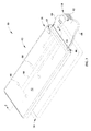
- FIG. 3 is a perspective view of a microclimate management system according to one embodiment of the current disclosure including a support device and a control system.
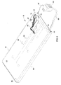
- FIG. 4 is a partial sectional view of the embodiment of FIG. 3 illustrating the controller and sensors positioned within a cover of the support device.
- FIG. 5 is a cross-sectional side view of the illustrative support device of FIG. 3 including a low air-loss topper positioned on top of the upper mattress surface of the mattress.
- FIG. 6 is a graph illustrating the relationship between the composition of the support device of FIG. 3 and the temperature of the skin contacting the support device over time, according to some principles of the present invention.
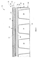
- FIG. 7 is a partial cross-sectional side view of the illustrative support device of FIG. 3 taken along line 5-5 with a person resting thereon illustrating the flow of air, heat, and moisture through the support device.
- FIG. 8 is a cross-sectional side view of a support device taken along line 5-5 of FIG. 3 according to another embodiment of the current disclosure including a low air-loss topper with bladders or a mattress with bladders.
- FIG. 9 is a cross-sectional side view of a support taken along line 5-5 of FIG. 3 according to another embodiment of the current disclosure including a low air-loss topper positioned within the mattress cover mattress.
- a microclimate management system including a support device, a fluid supply, and a controller having an instruction set that causes the controller to regulate the rate and temperature of fluid supplied by the fluid supply to maintain a heat withdrawal capacity of a least a portion of the person contacting surface below about 140W/m 2 .
- a microclimate management system can include a mattress, a topper supported on the mattress, and a control system configured to maintain at least one of the surface temperature, humidity, and heat withdrawal capacity of at least a portion of the person contacting surface within a predetermined range.
- a microclimate management system including a support device, a fluid supply, and a controller having an instruction set that causes the controller to regulate the rate and temperature of fluid supplied by the fluid supply to maintain a surface temperature of at least a portion of the person contacting surface above 31,1°C (88°F) and a relative humidity of at least a portion of the person contacting surface below about 95%.
- a fluid supply in communication with a topper is regulated as a function of at least one of the temperature and the relative humidity of at least a portion of the person contacting surface to maintain at least a portion of the person contacting surface within a predetermined operating range.
- a fluid supply in communication with a support device is regulated as a function of at least two of the temperature and the relative humidity of at least a portion of the person contacting surface and a user input to maintain at least a portion of the person contacting surface within a predetermined operating range.
- a fluid supply in communication with a topper is regulated as a function of at least one of the temperature and the relative humidity of at least a portion of the person contacting surface, and a user input to maintain at least a portion of the person contacting surface within a predetermined operating range.
- an apparatus in still a further illustrative embodiment, at least one of a rate and a temperature of a fluid supplied by a fluid supply to a support device is regulated as a function of the temperature and relative humidity of the person contacting surface to maintain the person contacting surface within a predetermined operating range.
- an apparatus includes a mattress, a topper, and a sensor configured to sense at least one of a temperature or a person contacting surface, a relative humidity of a person contacting surface, a temperature of the fluid within the topper, and a relative humidity of the fluid within the topper.
- a fluid supply is selected to cooperate with at least one of the fluid permeability parameter of the cover, the thickness parameter of the cover, the thermal conductivity of the cover, the fluid resistance parameter of the spacer, the fluid permeability parameter of the spacer, the thermal conductivity parameter of the spacer, and the thickness parameter of the spacer to maintain a heat withdrawal capacity of at least a portion of the person contacting surface below about 140 W/m 2 .
- At least one of the fluid permeability parameter of the cover, the thickness parameter of the cover, the thermal conductivity of the cover, the fluid resistance parameter of the spacer, the fluid permeability parameter of the spacer, the thermal conductivity parameter of the spacer, and the thickness parameter of the spacer is varied to cooperate with the fluid supply to maintain a heat withdrawal capacity of at least a portion of the person contacting surface below about 140 W/m 2
- a microclimate management system 10 can manage the temperature of a person's skin. Limiting skin warming can be accomplished by cooling the skin, which can reduces the metabolic demand of the tissue so that the tissue can withstand an exerted pressure for a longer period without breaking down, as shown in FIG. 1 . Cooling the skin to the point of excessive patient discomfort or hypothermia is preferably avoided.
- a microclimate management system 10 can also manage the accumulation of moisture against a person's skin.
- ischemia which is a restriction in blood supply generally due to factors in the blood vessels with resultant damage or dysfunction of tissue
- maceration which is the softening and weakening of the skin that occurs when its collagen linkages are dissolved over time
- limiting moisture accumulation can help decrease the coefficient of friction between the wet skin and common bedding materials, thereby reducing the forces imposed on the weakened skin for any sliding movement.
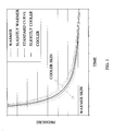
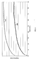
- Skin temperature can influence the perspiration rate or sweat rate of the skin, metabolic demand of the skin, and person's level of comfort, as shown in FIG. 2 , in which the x-axis corresponds to the temperature of the skin increasing from left to right (in degrees Fahrenheit) and the y-axis corresponds to scaled units representing the various dependent variables depicted.
- Curve S1 the sweat curve, illustrates the rate at which sweat is produced by the skin as the skin temperature varies.
- the sweat rate of the skin at a given location can be affected by the core temperature of the person, the person's mean skin temperature, and the local skin temperature.
- the sweat rate for a given patch of skin can increase as the patch of skin is warmed.
- the skin sweat rate can remain relatively constant at temperatures below a sweat threshold ST1 of approximately 35.3 °C (95.5 °F).
- the sweat rate below this threshold can be between about 5 g/m 2 -hr to 10 g/m 2 -hr. As the skin temperature increases beyond the sweat threshold the sweat rate can begin to rise dramatically.
- Curve MR1 shown in FIG. 2 , illustrates the extent to which the metabolic demand of the skin varies with the skin temperature. As the temperature of the skin increases, the demand for additional blood to be supplied to the skin can increases and the affected blood vessels can dilate to accommodate the demand. However, when high pressures are applied to the skin, dilation of the blood vessels can be impeded and nutrients may not be supplied to the skin at the necessary rate. This could result in a nutrient deficit leading to ischemic necrosis.
- Comfort curve C1 illustrates the level of patient comfort experienced while resting on the microclimate management system 10 as a function of the skin temperature. While a patient's comfort level is not an exact measurement and can differ from person to person for any given temperature, the comfort curve is generally representative of the comfort level for the majority of patients observed. Variations in the level of comfort can be due to factors including, but not limited to the person's body mass index, age, physical conditioning, personal preferences, and injury or illness.
- a person's skin can be maintained in one embodiment at a temperature below approximately 35.8 °C (96.5 °F), a temperature at which comfort begins to noticeably decline, as shown by curve C1 in FIG. 2 . More specifically, a person's skin can be maintained at a temperature below approximately 35.3 °C (95.5 °F), a temperature at which the sweat threshold ST1 is reached. Still more specifically, a person's skin can be maintained within a temperature range of about 32.2 °C (90 °F) and 35.3 °C (95.5 °F).
- the temperature of the skin can be maintained between about 31.1 °C (88 °F) and 35.8 °C (96.5 °F). It should be appreciated that the temperature of the skin can be maintained below 32.2 °C (90 °F); however, the risk of causing the person resting on the microclimate management system 10 to go into hypothermia increases as the temperature of the patient the skin decreases. It should also be appreciated that the temperature of the skin can be maintained above 35.8 °C (96.5 °F); however, the risk of increasing the occurrences of pressure ulcers increases as the temperature of the skin increases.
- the temperature of the skin can be maintained within the previously stated ranges for a minimum of 6 hours. More specifically, the temperature of the skin can be maintained within the previously stated temperature ranges for 12 hours or more. Still more specifically, the temperature of the skin can be maintained within the previously stated temperature ranges for 24 hours or more. In other embodiments the temperature of the skin can be maintained for less than 6 hours. It should be appreciated that other parameters, such as relative humidity and heat transfer rate, can be maintained within their respective ranges for the previously stated amounts of time.
- the temperature of the skin of a person on the microclimate management system 10 can depend upon the heat withdrawn from their skin.
- the total heat withdrawal capacity (THW capacity) parameter is the cooling power of the surface in Watts/m 2 with higher values indicating greater heat transfer.
- the THW capacity depends upon both the heat withdrawn due to dry flux and that removed due to wet flux.
- the dry flux measures the ability of a surface, such as the patient contacting surface 52 of the support apparatus 12 shown in FIG. 3 , to remove heat from the person's skin in the absence of moisture on the skin.
- the dry flux remains constant regardless of how much the skin is sweating.
- the wet flux represents the heat removed from the skin due to evaporation and is proportional to the evaporative capacity of a surface, such as the patient contacting surface 52 of the support apparatus 12 shown in FIG. 3 , interfacing with the skin.
- the evaporative capacity measures a surface's ability to keep the skin relatively dry and is a measure of the surface's ability to promote evaporation.
- the parameter is measured in g/m 2 -hr with higher values again indicating better performance.
- the support device 12 and material (not shown) positioned between the person and the support device 12 can have a THW capacity of between about 60 W/m 2 and 125 W/m 2 .
- the TWH capacity can be maintained between about 50 W/m 2 and 140 W/m 2 .
- the THW capacity can be maintained below 60 W/m 2 ; however, the risk of increasing occurrences of pressure ulcers increases as the THW capacity increases.
- the THW capacity can be maintained above 125 W/m 2 ; however, the risk of causing the person to go into hypothermia increases as the THW capacity decreases.
- the relative humidity of the skin of a person on the microclimate management system 10 can depend upon the heat removed from their skin due to evaporation.
- the support device 12 can have a relative humidity ("RH") between about 55% RH and 90% RH.
- RH relative humidity
- the relative humidity range can be maintained between about 20% RH and about 95% RH. It should be appreciated that the relative humidity can be maintained below 55% RH; however, the risk of drying the skin excessively and dehydrating the person increases as the relative humidity decreases. It should also be appreciated that the relative humidity can be maintained above 90% RH; however, the risk of saturating the skin and increasing the occurrences of pressure ulcers increases as the relative humidity increases.
- the microclimate management system 10 can be configured to maintain the skin about the aforementioned ranges as shown in FIGs. 3-5 .
- the microclimate management system 10 can include a support device 12 and a control system 14 adapted to manage the microclimate of the support device 12.
- the microclimate management system 10 can generally be used in the hospital setting on a hospital bed (not shown), stretcher (not shown), or other support structure to prevent the occurrences of pressure ulcers. It should be appreciated that the microclimate management system 10 can be used in any situation where a support device 12 is commonly used.
- the microclimate management system 10 can prevent the occurrences of pressure ulcers by reducing the accumulation of heat and moisture that tends to occur on a person's skin when the person is laid on the support device 12 in the supine position.
- Some of the types of support devices 12 utilized within the hospital setting today are: foam support devices and low air-loss support devices.
- the difference in skin temperature over time as the skin remains in contact with the foam support devices is illustrated by curve AA
- difference in skin temperature over time as the skin remains in contact with the low air-loss support devices is illustrated by curve BB, as shown in FIG. 6 .
- Foam support devices 12 can block the natural, basal level of heat and moisture produced by the skin that would normally flow into the atmosphere, whereas low air-loss support devices 12 can be adapted to remove accumulated heat and moisture. Blocking the heat and moisture produced warms and wets the skin over time, creating an environment that can differ markedly from the environment in which the skin was designed to operate.
- Low air-loss broadly refers to a feature of a support surface that provides a flow of air to assist in managing the heat and humidity (microclimate) of the skin.
- Convective evaporation evaporates accumulated moisture by blowing air on the skin.
- Diffusive evaporation evaporates accumulated moisture through and under the surface of the support device 12 to cool the skin without blowing air directly thereon.
- An example of a diffusive device can be seen in FIG.
- the support device 12 can include a mattress 16 and a topper 18 as shown in FIG. 3 .
- the topper 18 can be positioned on top of the mattress 16 and can be removably coupled to the mattress 16 by a plurality of fasteners (not shown), such as, buttons, snaps, Velcro®, ties, pins, zippers, or other known fasteners, to prevent movement of the topper 18 with respect to the mattress 16.
- fasteners such as, buttons, snaps, Velcro®, ties, pins, zippers, or other known fasteners, to prevent movement of the topper 18 with respect to the mattress 16.
- the topper 18 can be integrally incorporated in the mattress 16 or can be configured to mimic the structure of the mattress 16 as shown in FIGs. 8 & 9 .
- the mattress 16 can include an outer mattress cover 20 or mattress ticking 20 that can define a mattress chamber 22.
- the mattress ticking 20 can have a lower mattress surface 24 that can interface with the hospital bed (not shown), and an upper mattress surface 26 that can interface with the LAL topper 18.
- the mattress chamber 22 can contain a plurality of air mattress bladders 28 and a mattress spacer 30 therein. It should be appreciated that the mattress 18 can contain only one mattress bladder 28 within the mattress chamber 22. It should also be appreciated that the mattress 18 can be composed of a polymeric material, such as, foam, or a combination of polymeric material and bladders.
- the mattress bladders 28 can be alternately inflated and deflated to create a form of alternating pressure therapy.
- the bladders 28 can also be in communication with one another such that the fluid pressure in the bladders 28 can be maintained as pressure exerted on the bladders 28.
- the bladders 28 can include holes HO therein that allow for fluid therein to be communicated from the bladders 28 into the mattress chamber 22 as shown in FIG. 8 .
- the bladders 28 can include other components, such as, bladders 28, for assisting with the turning of a patient, for assisting with lateral rotation of a patient, or other therapy or support bladders 28.
- the LAL topper 18 can be a low air-loss topper 18 (LAL topper 18) that can include an outer LAL cover 40 or LAL ticking 40 that can define a LAL chamber 42, an inlet 44, a vent 46, and a three-dimensionally engineered spacer 48.
- the LAL ticking 40 can include a lower LAL surface 50 and an upper LAL surface 52 or patient contacting surface 52.
- the lower LAL surface 50 can interface with the upper mattress surface 28.
- the patient contacting surface 52 can interface with a patient P1 lying thereon as shown in FIG. 7 .
- the patient P1 can be separated from the patient contacting surface 52 by material (not shown), such as bedding, clothing, or other such garments or materials, that has a total thermal conductivity of anywhere from about .02 W/m - K to 1000 W/m - K.
- the lower LAL surface 50 and the patient contacting surface 52 can be generally shaped to cooperate with the upper mattress surface 26 and can be secured to one another along their respective edges by ultrasonic welding in order to form a fluid-tight seal. It should be appreciated that the lower LAL surface 50 and the patient contacting surface 52 can be secured to one another by adhesive, plastic welding, or other securing means, and can be secured along various portions of the lower LAL surface 50 and the patient contacting surface 52.
- the LAL ticking 40 of this illustrative embodiment can be moisture permeable and air impermeable. It should be appreciated that the LAL ticking 40 can be both moisture permeable and air permeable. It should also be appreciated that the mattress ticking 20 and the LAL ticking 40 can be composed of the same material and have the same physical characteristics.
- the moisture vapor transfer rate for the LAL ticking 40 when fluid is being supplied to the LAL topper 18 at a rate of 0,2m 2 /min (2.2 ft 3 /min), can be at least about 20 g/m 2 -hr in order to accommodate basal skin moisture production.
- the moisture vapor transfer rate of the LAL ticking 40 can be 80 g/m 2 -hr or more.
- the moisture vapor transfer rate can be between 25 g/m 2 -hr and 200 g/m 2 -hr. It should be appreciated that the moisture vapor transfer rate can be less than about 20 g/m 2 -hr; however, the amount of moisture accumulation on the skin can increase with time and can increase the risk of maceration.
- the inlet 44 can be positioned along a side of the LAL topper 18 and can allow for fluid to be communicated from the control system 14 into the LAL chamber 42.
- the inlet 44 can include an inlet coupler 54 that can couple the control system 14 to the LAL topper 18. It should be appreciated that the inlet coupler 54 can be secured to the LAL topper 18 such that there is a fluid tight seal between the inlet coupler 54 and the LAL topper 18.
- the vent 46 or outlet 46 can be positioned along a side of the LAL topper 18 opposite the inlet 44.
- the vent 46 can be an opening in the lower LAL surface 50 that can allow fluid entering the inlet 44 and passing through the LAL chamber 42 to exit the LAL topper 18. It should be appreciated that the vent 46 can be a portion of the edges of the lower LAL surface 50 and the patient contacting surface 52 that were not secured to one another. It should also be appreciated that the vent 46 can be secured to the lower LAL surface 50 or the patient contacting surface 52 opposite the inlet 44.
- the three-dimensionally engineered spacer 48 can be positioned within the LAL chamber 42 and can separate the lower LAL surface 50 from the patient contacting surface 52.
- the three-dimensionally engineered spacer 48 can be composed of SpaceNet®, which is a product of Freudenberg. It should be appreciated that the three-dimensionally engineered spacer 48 can be composed of other materials having a high fluid porosity and having some resistance against flattening. It should also be appreciated that the three-dimensionally engineered spacer 42 can include at least one chamber and/or bladder (not shown) therewithin. It should also be appreciated that the mattress spacer 30 and the three-dimensionally engineered spacer 48 can be composed of the same material and have the same physical characteristics.
- the resistance to flow for the three-dimensionally engineered spacer 48 when fluid is supplied to the LAL topper 18 at a rate of 0,2m 2 /min (2.2 ft 3 /min) can be less than about 1 (lb./in 2 )/( ft 3 /min.). In one illustrative embodiment, the resistance to flow for the three-dimensionally engineered spacer 48 can be between about 0,25 bar/m 3 /min(.1 (lbs./in 2 )/( ft 3 /min)) and 1,7 bar/m 3 /min (7 (lbs./in 2 )/( ft 3 /min.)).
- the resistance to flow can be more than 2,5 bar/m 3 /min (1 (lb./in 2 )/( ft 3 /min.)). It should be appreciated that the moisture vapor transfer rate can be between 25 g/m 2 -hr and 200 g/m 2 -hr.
- t thickness of the three-dimensionally engineered spacer 48 can be between about 2,5 mm (1 in) and 19,1 mm(75 in.) It should be appreciated that the thickness of the three-dimensionally engineered spacer 48 can be greater than (19,1 mm (.75 in).
- the control system 14 includes a plurality of sensors 60, a fluid supply 62, and a controller 64 as shown in FIGs. 3 & 4 .
- the sensors 60 are temperature sensors and moisture sensors adapted to generate signals corresponding to the temperature and relative humidity of the patient contacting surface 52.
- the sensors 60 can be positioned within the LAL ticking 40 and can be operatively coupled with the controller 64 via a wire 66. It should be appreciated that the sensors 60 can be coupled to the patient contacting surface 52 or coupled within the LAL chamber 42. It should also be appreciated that the sensors 60 can communicate wirelessly with the controller 64.
- the fluid supply 62 can be an air blower 62 that can supply air to the LAL topper 18. It should be appreciated that the fluid supply 62 can supply a various other gasses and/or liquids.
- the fluid supply 62 can removably couple with the LAL topper 18 via a hose 68. It should be appreciated that the fluid supply 62 can connect directly to the LAL topper 18. It should also be appreciated that the blower can be integrated or partially integrated within the mattress 16 or LAL topper 18.
- the fluid supply 62 may also include a heating element (not shown) and/or cooling element (not shown) that can heat and/or cool the fluid being supplied.
- Determining what characteristics the fluid supply 62 can have in order to meet the desired range(s) can depend on the physical characteristics of the materials included in the support device 12, as well as any material (not shown) positioned between the patient P1 and the support device 12.
- the fluid supply can be configured to supply fluid to the LAL topper 18 at a rate of 0,2m 3 /min 2.2 ft 3 /min. and at a temperature of about 18.3 °C (65 °F) to 29.4 °C (85 °F) so that the temperature of the fluid flowing directly beneath the LAL ticking 40 portion proximate the sacrum is about 29.4 °C (85 °F) to 35 °C (95 °F).
- the fluid supply 62 can supply fluid at a rate of 0,2m 3 /min (2.2 ft 3 /min). and at a temperature of about 18.3 °C (65 °F) to 29.4 °C (85 °F) to the mattress 16. It should further be appreciated that the fluid supply 62 can supply fluid at a temperature of about -3.9 °C (25 °F) to 29.4 °C (85 °F). It should also be appreciated that the fluid supply 62 can be required to supply fluid at a rate higher or lower than 2.2 ft 3 /min. and/or at a temperature lower than the aforementioned range based on the physical characteristics of the materials included in the support device 12 and positioned between the patient P 1 and the support device 12.
- the controller 64 can be operatively coupled to the fluid supply 62 and the sensors 60, and can be positioned within the LAL chamber 42 of the LAL topper 18 as shown in FIGs. 3 & 4 . It should be appreciated that the controller 64 may be mounted to the mattress 16, a hospital be frame (not shown), a footboard (not shown), the fluid supply 62, or other support structures. It should also be appreciated that the controller 64 can be integrated into the fluid supply 62, a hospital bed control system (not shown), or other control systems configured to regulate the fluid supply 62.
- the controller 64 can include a processor 70 and memory 72 electrically coupled to the processor 70.
- the processor 70 can process the signals received from the sensors 60 and can execute instructions stored in the memory 72.
- the instructions can cause the controller 64 to regulate operation of the fluid supply 62 in accordance with the signals from the sensors 60 in order to maintain the temperature and/or relative humidity of the patient contacting surface 52 about the aforementioned ranges.
- the controller 64 can also receive a user input signal from a user input device (not shown) that allows the patient P1 to influence the regulation of the fluid supply 62. It should be appreciated that the user input signal can only influence the regulation of the fluid supply 62 within the aforementioned temperature and/or relative humidity ranges.
- the fluid supply 62 can be initiated and fluid can be supplied through the hose 66 to the inlet 44 of the LAL topper 18.
- the fluid can flow into the LAL chamber 42, through the three-dimensionally engineered spacer 48, and out the vent 46.
- the temperature and relative humidity of the patient contacting surface 52 can be maintained within the predetermined temperature and relative humidity ranges, such as, the ranges described earlier.
- the sensors 60 can generate signals representative of the temperature and relative humidity of the patient contact surface 52 and communicate the signals to the processor 70 of the controller 64.
- the processor 70 can process the signals and can execute the instructions stored in the memory 72 in accordance with the signals from the sensors 60 to regulate operation of the fluid supply 62 in accordance with the signals. It should be appreciated that a patient P1 need not be contacting the support device 12 for regulation of the temperature and relative humidity of the patient contacting surface 52 to occur.
- a microclimate management system 10 comprises a support device 12, a fluid supply 62, and a controller 64.
- the support device 12 includes a person contacting surface 52.
- the fluid supply 62 couples with the support device 12 and supplies fluid to the support device 12.
- the controller 64 is operatively coupled to the fluid supply 62 and includes an instruction set.
- the instruction set causes the controller 64 to regulate at least one of the rate the fluid is supplied by the fluid supply 62 and temperature of the fluid supplied by the fluid supply 62 to maintain a heat withdrawal capacity of at least a portion of the person contacting surface 52 below about 140 W/m 2 ..
- a microclimate management system 10 comprises a mattress 16, a topper 18, and a control system 14.
- the topper 18 is coupled to the mattress 16 and is supported thereon.
- the topper 18 defines an interior region 42 and a person contacting surface 52.
- the control system 14 is configured to maintain at least one of a surface temperature, a relative surface humidity, and a heat withdrawal capacity of at least a portion of the person contacting surface 52 within a predetermined operating range.
- a microclimate management system 10 comprises a support device 12, a fluid supply 62, and a controller 64.
- the support device 12 includes a person contacting surface 52.
- the fluid supply 62 is coupled with the support device 12 and supplies fluid to the support device 12.
- the controller 64 includes an instruction set. The instruction set causes the controller 64 to regulate at least one of the rate the fluid is supplied by the fluid supply 62 and temperature of the fluid supplied by the fluid supply 62 to maintain a surface temperature of at least a portion of the person contacting surface 52 above about 88° Fahrenheit and a relative humidity of at least a portion of the person contacting surface 52 below about 95%.
- At least one of a relative humidity and a temperature of at least a portion of a person contacting surface 52 of a topper 18 coupled on a mattress 16 is sensed.
- a fluid supply 62 in communication with the topper 18 is regulated as a function of at least one of the temperature of at least a portion of the person contacting surface 52 and the relative humidity of at least a portion of the person contacting surface 52 to maintain at least a portion of the person contacting surface 52 within a predetermined operating range.
- At least one of a relative humidity and a temperature of at least a portion of a person contacting surface 52 of a support device 12 is sensed.
- a person comfort input signal is received from an input device 60.
- a a fluid supply 62 in communication with the support device 12 is regulated as a function of at least two of the temperature of at least a portion of the person contacting surface 52, the relative humidity of at least a portion of the person contacting surface 52, and the person comfort input signal to maintain at least a portion of the person contacting surface 52 within a predetermined operating range.
- At least one of a relative humidity and a temperature of at least a portion of a person contacting surface 52 of a topper 18 coupled on a mattress 16 is sensed.
- a person comfort input signal is received from an input device 60.
- a fluid supply 62 in communication with the topper 18 is regulated as a function of at least one of the temperature of at least a portion of the person contacting surface 52, the relative humidity of at least a portion of the person contacting surface 52, and the person comfort input signal to maintain at least a portion of the person contacting surface 52 within a predetermined operating range.
- a relative humidity and a temperature of a person contacting surface 52 of a support device 12 is sensed. At least one of a rate and a temperature of fluid supplied by a fluid supply 62 to the support device 12 is regulated as a function of the temperature of the person contacting surface 52 and the relative humidity of the person contacting surface 52 to maintain the person contacting surface 52 within a predetermined operating range.
- an apparatus comprises a mattress 16, a topper 18, and a sensor 60.
- the topper 18 is coupled on the mattress 16.
- the topper 18 includes a cover 40 and has fluid communicated through at least a portion of the topper 18.
- the topper 18 defines an interior region 42 and a portion of the cover 40 defines a person contacting surface 52.
- the sensor 60 is configured to sense at least one of a temperature of the person contacting surface 52 a relative humidity of the person contacting surface 52, a temperature of the fluid within the topper 18, and a relative humidity of the fluid within the topper 18.
- a support device 12 is provided.
- the support device 12 includes a cover 40and a spacer 48.
- the cover 40 defines an interior region 42 and at least a portion of the cover 40 defines a person contacting surface 52.
- the cover 40 also defines a fluid permeability parameter, a thermal conductivity parameter, and a thickness parameter.
- the spacer 48 is positioned within the interior region 42.
- the spacer 48 defines a fluid resistance parameter, a fluid permeability parameter, a thermal conductivity parameter, and a thickness parameter.
- a fluid supply 62 is selected to cooperate with at least one of the fluid permeability parameter of the cover 40, the thickness parameter of the cover 40, the thermal conductivity of the cover 40, the fluid resistance parameter of the spacer 48, the fluid permeability parameter of the spacer 48, the thermal conductivity parameter of the spacer 48, and the thickness parameter of the spacer 48 to maintain a heat withdrawal capacity of at least a portion of the person contacting surface 52 below about 140 W/m 2 .
- a support device 12 is provided.
- the support device 12 includes a cover 40 and a spacer 48.
- the cover 40 defines an interior region 42 and at least a portion of the cover 40 defines a person contacting surface 52.
- the cover 40 also defines a fluid permeability parameter, a thermal conductivity parameter, and a thickness parameter.
- the spacer 48 is positioned within the interior region 42.
- the spacer 48 defines a fluid resistance parameter, a fluid permeability parameter, a thermal conductivity parameter, and a thickness parameter.
- At least one of the fluid permeability parameter of the cover 40, the thickness parameter of the cover 40, the thermal conductivity of the cover 40, the fluid resistance parameter of the spacer 48, the fluid permeability parameter of the spacer 48, the thermal conductivity parameter of the spacer 48, and the thickness parameter of the spacer 48 is varied to cooperate with the fluid supply 62 to maintain a beat withdrawal capacity of at least a portion of the person contacting surface 52 below about 140 W/m 2 .
Landscapes
- Health & Medical Sciences (AREA)
- General Health & Medical Sciences (AREA)
- Veterinary Medicine (AREA)
- Public Health (AREA)
- Life Sciences & Earth Sciences (AREA)
- Animal Behavior & Ethology (AREA)
- Nursing (AREA)
- Vascular Medicine (AREA)
- Heart & Thoracic Surgery (AREA)
- Biomedical Technology (AREA)
- Engineering & Computer Science (AREA)
- Mattresses And Other Support Structures For Chairs And Beds (AREA)
- Investigating Or Analyzing Materials Using Thermal Means (AREA)
- Bedding Items (AREA)
- Air Conditioning Control Device (AREA)
- Invalid Beds And Related Equipment (AREA)
Claims (14)
- Système de gestion de microclimat (10) comprenant un dispositif de support (12) englobant une surface de contact avec une personne (52), une alimentation en fluide (62) couplée au dispositif de support (12) et alimentant en fluide le dispositif de support (12), et un contrôleur (64) couplé d'une manière opérationnelle à l'alimentation en fluide (62) et englobant un jeu d'instructions, le jeu d'instructions faisant que le contrôleur (64) régule au moins l'une d'entre la vitesse à laquelle le fluide est fourni par l'alimentation en fluide (62) et la température du fluide fourni par l'alimentation en fluide (62) et des capteurs (60) couplés de manière opérationnelle au contrôleur (64), caractérisé en ce que les capteurs (60) sont des capteurs (60) de température et d'humidité configurés pour fournir des signaux indicatifs de la température et de l'humidité de la surface de contact avec une personne (52), et en ce que la régulation par le contrôleur (64) est destinée à maintenir une capacité d'extraction de chaleur d'au moins une partie de la surface de contact avec une personne (52) au-dessous d'environ 140 W/m2.
- Système de gestion de microclimat (10) selon la revendication 1, dans lequel la capacité d'extraction de chaleur d'au moins une partie de la surface de contact avec une personne (52) est maintenue au-dessus d'environ 50 W/m2.
- Système de gestion de microclimat (10) selon la revendication 1, dans lequel la capacité d'extraction de chaleur d'au moins une partie de la surface de contact avec une personne (52) est maintenue entre environ 60 W/m2 et environ 125 W/m2.
- Système de gestion de microclimat (10) selon la revendication 1, dans lequel la température de la surface de contact avec une personne (52) est maintenue au-dessous d'environ 35,8°C (96,5°F).
- Système de gestion de microclimat (10) selon la revendication 1, dans lequel la température de la surface de contact avec une personne (52) est maintenue au-dessus d'environ 31,1°C (88°F).
- Système de gestion de microclimat (10) selon la revendication 1, dans lequel la température de la surface de contact avec une personne (52) est maintenue entre environ 32,2°C (90°F) et environ 35,3°C (95,5°F).
- Système de gestion de microclimat (10) selon la revendication 1, dans lequel l'humidité relative de la surface de contact avec une personne (52) est maintenue au-dessous d'environ 95%.
- Système de gestion de microclimat (10) selon la revendication 1, dans lequel l'humidité relative de la surface de contact avec une personne (52) est maintenue au-dessus d'environ 20%.
- Système de gestion de microclimat (10) selon la revendication 1, dans lequel l'humidité relative de la surface de contact avec une personne (52) est maintenue entre environ 55% et environ 90%.
- Système de gestion de microclimat (10) selon l'une quelconque des revendications précédentes, dans lequel le dispositif de support (12) comprend une couverture (40) définissant une région intérieure (42) et une partie de la couverture (40) définissant la surface de contact avec une personne (52), les capteurs (60) étant intégrés dans la couverture (40).
- Système de gestion de microclimat (10) selon l'une quelconque des revendications 1 à 9, dans lequel les capteurs (60) sont positionnés dans la région intérieure (42) à proximité de la surface de contact avec une personne (52).
- Système de gestion de microclimat (10) selon la revendication 1, dans lequel le dispositif de support (12) comprend un matelas (16) et un surmatelas (18) couplé au matelas (16), le surmatelas (18) englobe une couverture (40) définissant une région intérieure (42) et une partie de la couverture (42) définissant la surface de contact avec une personne (52).
- Système de gestion de microclimat (10) selon la revendication 1, comprenant en plus un dispositif d'entrée (60) configuré pour recevoir une entrée d'une personne indicative du niveau de confort de la personne, où le jeu d'instructions fait que le contrôleur (64) régule en plus l'alimentation en fluide (62) en fonction de l'entrée du dispositif d'entrée (60).
- Procédé de fabrication d'un système de gestion de microclimat (10), comprenant :fournir un dispositif de support (12), le dispositif de support (12) comprenant :une couverture (40) définissant une région intérieure (42) et au moins une partie de la couverture (40) définissant une surface de contact avec une personne (52), la couverture (40) définissant aussi un paramètre de perméabilité au fluide, un paramètre de conductivité thermique et un paramètre d'épaisseur et un dispositif d'espacement (48) positionné dans la région intérieure (42), le dispositif d'espacement (48) définissant un paramètre de résistance au fluide, un paramètre de perméabilité au fluide, un paramètre de conductivité thermique et un paramètre d'épaisseur, et des capteurs (60) couplés d'une manière opérationnelle au contrôleur (64), les capteurs (60) étant des capteurs (60) de température et d'humidité configurés pour fournir des signaux indicatifs de la température et de l'humidité de la surface de contact avec une personne (52) et sélectionnant une alimentation en fluide (62) destinée à coopérer avec au moins l'un d'entre le paramètre de perméabilité au fluide de la couverture (40), le paramètre d'épaisseur de la couverture (40), le paramètre de conductivité thermique de la couverture (40), le paramètre de résistance au fluide du dispositif d'espacement (48), le paramètre de perméabilité au fluide du dispositif d'espacement (48), le paramètre de conductivité thermique du dispositif d'espacement (48) et le paramètre d'épaisseur du dispositif d'espacement (48), afin de maintenir une capacité d'extraction de chaleur d'au moins une partie de la surface de contact avec une personne (52) au-dessous d'environ 140 W/m2.
Priority Applications (2)
| Application Number | Priority Date | Filing Date | Title |
|---|---|---|---|
| EP13184257.7A EP2702966B1 (fr) | 2008-04-15 | 2009-04-15 | Système de gestion de microclimat |
| EP12197210.3A EP2594234A3 (fr) | 2008-04-15 | 2009-04-15 | Système de gestion de microclimat |
Applications Claiming Priority (2)
| Application Number | Priority Date | Filing Date | Title |
|---|---|---|---|
| US4511108P | 2008-04-15 | 2008-04-15 | |
| PCT/US2009/040661 WO2009129306A1 (fr) | 2008-04-15 | 2009-04-15 | Système de gestion de microclimat |
Related Child Applications (2)
| Application Number | Title | Priority Date | Filing Date |
|---|---|---|---|
| EP12197210.3A Division EP2594234A3 (fr) | 2008-04-15 | 2009-04-15 | Système de gestion de microclimat |
| EP13184257.7A Division EP2702966B1 (fr) | 2008-04-15 | 2009-04-15 | Système de gestion de microclimat |
Publications (2)
| Publication Number | Publication Date |
|---|---|
| EP2276437A1 EP2276437A1 (fr) | 2011-01-26 |
| EP2276437B1 true EP2276437B1 (fr) | 2012-12-19 |
Family
ID=41050399
Family Applications (3)
| Application Number | Title | Priority Date | Filing Date |
|---|---|---|---|
| EP12197210.3A Withdrawn EP2594234A3 (fr) | 2008-04-15 | 2009-04-15 | Système de gestion de microclimat |
| EP13184257.7A Active EP2702966B1 (fr) | 2008-04-15 | 2009-04-15 | Système de gestion de microclimat |
| EP09733293A Active EP2276437B1 (fr) | 2008-04-15 | 2009-04-15 | Système de gestion de microclimat |
Family Applications Before (2)
| Application Number | Title | Priority Date | Filing Date |
|---|---|---|---|
| EP12197210.3A Withdrawn EP2594234A3 (fr) | 2008-04-15 | 2009-04-15 | Système de gestion de microclimat |
| EP13184257.7A Active EP2702966B1 (fr) | 2008-04-15 | 2009-04-15 | Système de gestion de microclimat |
Country Status (3)
| Country | Link |
|---|---|
| US (1) | US20110024076A1 (fr) |
| EP (3) | EP2594234A3 (fr) |
| WO (1) | WO2009129306A1 (fr) |
Cited By (3)
| Publication number | Priority date | Publication date | Assignee | Title |
|---|---|---|---|---|
| US11322258B2 (en) | 2012-05-22 | 2022-05-03 | Hill-Rom Services, Inc. | Adverse condition detection, assessment, and response systems, methods and devices |
| US11559421B2 (en) | 2015-06-25 | 2023-01-24 | Hill-Rom Services, Inc. | Protective dressing with reusable phase-change material cooling insert |
| US11583437B2 (en) | 2018-02-06 | 2023-02-21 | Aspen Surgical Products, Inc. | Reusable warming blanket with phase change material |
Families Citing this family (17)
| Publication number | Priority date | Publication date | Assignee | Title |
|---|---|---|---|---|
| US8856993B2 (en) | 2008-04-15 | 2014-10-14 | Hill-Rom Services, Inc. | Temperature and moisture regulating topper for non-powered person-support surfaces |
| EP2246024A3 (fr) * | 2009-04-28 | 2014-05-21 | Hill-Rom Services, Inc. | Système de gestion de microclimat |
| US8332975B2 (en) | 2009-08-31 | 2012-12-18 | Gentherm Incorporated | Climate-controlled topper member for medical beds |
| US8845562B2 (en) | 2010-07-21 | 2014-09-30 | Hill-Rom Services, Inc. | Gas supply system |
| US9295600B2 (en) | 2011-04-08 | 2016-03-29 | Hill-Rom Services, Inc. | Person support apparatus with activity and mobility sensing |
| US20120259245A1 (en) | 2011-04-08 | 2012-10-11 | Receveur Timothy J | Person support apparatus with activity and mobility sensing |
| AU2012202456A1 (en) * | 2011-05-03 | 2012-11-22 | Hill-Rom Services, Inc. | Temperature and moisture regulating topper for non-powered person-support surfaces |
| CN103945802B (zh) * | 2011-11-21 | 2017-06-09 | 皇家飞利浦有限公司 | 用于改进人的睡眠的系统和方法 |
| US9333136B2 (en) | 2013-02-28 | 2016-05-10 | Hill-Rom Services, Inc. | Sensors in a mattress cover |
| US20140358303A1 (en) * | 2013-06-03 | 2014-12-04 | Tescom Corporation | Method and Apparatus for Stabilizing Pressure in an Intelligent Regulator Assembly |
| US9711029B2 (en) | 2014-10-31 | 2017-07-18 | Hill-Rom Services, Inc. | Equipment, dressing and garment wireless connectivity to a patient bed |
| US20180000633A1 (en) * | 2016-07-01 | 2018-01-04 | Hill-Rom Services, Inc. | Microclimate management system with wireless sensors |
| US10945679B2 (en) | 2017-01-31 | 2021-03-16 | Welch Allyn, Inc. | Modular monitoring smart bed |
| US20180220960A1 (en) * | 2017-02-07 | 2018-08-09 | Sheng Yang | Systems and methods for measuring caloric expenditure |
| EP3642846A4 (fr) * | 2017-06-23 | 2021-01-27 | 3M Innovative Properties Company | Système de réchauffement de patient avec capacité de surveillance et de rétroaction |
| US11367535B2 (en) | 2018-09-30 | 2022-06-21 | Hill-Rom Services, Inc. | Patient care system for a home environment |
| US12042440B1 (en) | 2021-04-16 | 2024-07-23 | Turn Medical, LLC | Stowable patient supports |
Citations (1)
| Publication number | Priority date | Publication date | Assignee | Title |
|---|---|---|---|---|
| WO2002005736A2 (fr) * | 2000-07-13 | 2002-01-24 | Medtronic, Inc. | Dispositif medical non-infractif de refroidissement des carotides pour hypothermie cerebrale |
Family Cites Families (41)
| Publication number | Priority date | Publication date | Assignee | Title |
|---|---|---|---|---|
| US4066072A (en) * | 1976-02-12 | 1978-01-03 | Cummins Betty L | Comfort cushion for infants |
| GB2070174A (en) * | 1980-02-26 | 1981-09-03 | Watkins & Watson Ltd | Conduit connector |
| CA1309560C (fr) * | 1986-09-09 | 1992-11-03 | John H. Vrzalik | Methode et appareil pour alterner la pression d'un systeme de soutien du patient avec faible perte d'air |
| US6115860A (en) * | 1986-09-09 | 2000-09-12 | Kinetic Concepts, Inc. | Feedback controlled patient support |
| US4949412A (en) * | 1986-11-05 | 1990-08-21 | Air Plus, Inc. | Closed loop feedback air supply for air support beds |
| US5005240A (en) * | 1987-11-20 | 1991-04-09 | Kinetics Concepts, Inc. | Patient support apparatus |
| NL8800792A (nl) * | 1988-03-29 | 1989-10-16 | Redactron Bv | Werkwijze en inrichting voor het onttrekken van vocht aan een of meer lichamen. |
| US5483709A (en) * | 1994-04-01 | 1996-01-16 | Hill-Rom Company, Inc. | Low air loss mattress with rigid internal bladder and lower air pallet |
| US5109560A (en) * | 1991-09-18 | 1992-05-05 | Keisei Medical Industrial Co., Ltd. | Ventilated air mattress with alternately inflatable air cells having communicating upper and lower air chambers |
| JP2876882B2 (ja) * | 1992-04-02 | 1999-03-31 | 松下電器産業株式会社 | 寝室温度湿度制御装置 |
| JP2630733B2 (ja) * | 1993-12-20 | 1997-07-16 | 裕子 鈴木 | エアーコントロールふとん |
| US5493742A (en) * | 1994-05-10 | 1996-02-27 | Lake Medical Products, Inc. | Ventilating air mattress with an inflating quilted pad |
| US5509154A (en) * | 1994-11-01 | 1996-04-23 | Select Comfort Corporation | Air control system for an air bed |
| US5894615A (en) | 1995-10-25 | 1999-04-20 | Alexander; Marvin J. | Temperature selectively controllable body supporting pad |
| US5815864A (en) * | 1996-04-02 | 1998-10-06 | Sytron Corporation | Microprocessor controller and method of initializing and controlling low air loss floatation mattress |
| GB9610233D0 (en) * | 1996-05-16 | 1996-07-24 | Kci Medical Ltd | Mattress cooling system |
| US5699570A (en) * | 1996-06-14 | 1997-12-23 | Span-America Medical Systems, Inc. | Pressure relief valve vent line mattress system and method |
| US5800480A (en) * | 1996-08-30 | 1998-09-01 | Augustine Medical, Inc. | Support apparatus with a plurality of thermal zones providing localized cooling |
| SE506911C2 (sv) * | 1996-10-17 | 1998-03-02 | Yvonne Olofsson | Anordning vid reglerad temperering av hårbotten |
| JP2001506877A (ja) * | 1996-11-25 | 2001-05-29 | キネティック・コンセプツ・インコーポレイテッド | 患者支持体と利用する温度制御 |
| US6018819A (en) * | 1998-04-15 | 2000-02-01 | Bha Technologies, Inc. | Garment with moisture vapor transmissive wind barrier panels |
| US6721980B1 (en) * | 1998-10-28 | 2004-04-20 | Hill-Fom Services, Inc. | Force optimization surface apparatus and method |
| US6197045B1 (en) * | 1999-01-04 | 2001-03-06 | Medivance Incorporated | Cooling/heating pad and system |
| US6208250B1 (en) * | 1999-03-05 | 2001-03-27 | Hill-Rom, Inc. | Patient position detection apparatus for a bed |
| US6933469B2 (en) * | 2000-06-14 | 2005-08-23 | American Healthcare Products, Inc. | Personal warming systems and apparatuses for use in hospitals and other settings, and associated methods of manufacture and use |
| US6855158B2 (en) * | 2001-09-11 | 2005-02-15 | Hill-Rom Services, Inc. | Thermo-regulating patient support structure |
| GB0122764D0 (en) * | 2001-09-21 | 2001-11-14 | Caldwell Kenneth | Matress or like body supporting device |
| JP2004121837A (ja) * | 2002-09-11 | 2004-04-22 | Sanyo Electric Co Ltd | 可動ベッド |
| SE524903C2 (sv) * | 2003-02-04 | 2004-10-19 | Hilding Anders Internat Ab | Anordning och förfarande för att reglera fysikaliska egenskaper hos en säng |
| CA2547263C (fr) * | 2004-01-22 | 2012-05-22 | Office Of The Staff Judge Advocate | Thermoregulation corporelle mettant en oeuvre la retroaction de la temperature de la peau |
| US20070162097A9 (en) * | 2004-03-16 | 2007-07-12 | Rojas Arturo R | Patient cooling system and method |
| US7469436B2 (en) * | 2004-04-30 | 2008-12-30 | Hill-Rom Services, Inc. | Pressure relief surface |
| US7572285B2 (en) * | 2005-02-18 | 2009-08-11 | Smiths Medical Asd, Inc. | System for providing actuated optimal inflation to multiple temperature regulated blankets and method therefor |
| US7181787B2 (en) * | 2005-07-01 | 2007-02-27 | Shin-Tsai Wu | Air mattress assembly having heating device |
| US20070056101A1 (en) * | 2005-09-08 | 2007-03-15 | Ajay Mahajan | Sensor based mattress/seat for monitoring pressure, temperature and sweat concentration to prevent pressure ulcerations |
| DK200600501A (da) * | 2006-04-07 | 2007-10-08 | Inspiri Aps | Overvågningssystem |
| US20070268955A1 (en) | 2006-05-17 | 2007-11-22 | Pohl Hermann K | Thermal fluid device with remote temperature indicator |
| US7469572B2 (en) * | 2006-07-17 | 2008-12-30 | Kci Licensing, Inc. | Measurement of moisture vapor transfer rate |
| GB2447287B (en) * | 2007-03-08 | 2011-11-23 | Anne Kathleen Paton | Personal temperature control device |
| US20080263776A1 (en) * | 2007-04-30 | 2008-10-30 | Span-America Medical Systems, Inc. | Low air loss moisture control mattress overlay |
| US20090000031A1 (en) * | 2007-06-29 | 2009-01-01 | Steve Feher | Multiple convective cushion seating and sleeping systems and methods |
-
2009
- 2009-04-15 EP EP12197210.3A patent/EP2594234A3/fr not_active Withdrawn
- 2009-04-15 WO PCT/US2009/040661 patent/WO2009129306A1/fr active Application Filing
- 2009-04-15 EP EP13184257.7A patent/EP2702966B1/fr active Active
- 2009-04-15 EP EP09733293A patent/EP2276437B1/fr active Active
- 2009-04-15 US US12/937,306 patent/US20110024076A1/en not_active Abandoned
Patent Citations (1)
| Publication number | Priority date | Publication date | Assignee | Title |
|---|---|---|---|---|
| WO2002005736A2 (fr) * | 2000-07-13 | 2002-01-24 | Medtronic, Inc. | Dispositif medical non-infractif de refroidissement des carotides pour hypothermie cerebrale |
Cited By (3)
| Publication number | Priority date | Publication date | Assignee | Title |
|---|---|---|---|---|
| US11322258B2 (en) | 2012-05-22 | 2022-05-03 | Hill-Rom Services, Inc. | Adverse condition detection, assessment, and response systems, methods and devices |
| US11559421B2 (en) | 2015-06-25 | 2023-01-24 | Hill-Rom Services, Inc. | Protective dressing with reusable phase-change material cooling insert |
| US11583437B2 (en) | 2018-02-06 | 2023-02-21 | Aspen Surgical Products, Inc. | Reusable warming blanket with phase change material |
Also Published As
| Publication number | Publication date |
|---|---|
| WO2009129306A1 (fr) | 2009-10-22 |
| EP2594234A2 (fr) | 2013-05-22 |
| EP2702966B1 (fr) | 2019-07-17 |
| EP2702966A3 (fr) | 2014-04-23 |
| EP2594234A3 (fr) | 2014-04-23 |
| EP2276437A1 (fr) | 2011-01-26 |
| EP2702966A2 (fr) | 2014-03-05 |
| US20110024076A1 (en) | 2011-02-03 |
Similar Documents
| Publication | Publication Date | Title |
|---|---|---|
| EP2276437B1 (fr) | Système de gestion de microclimat | |
| EP2246024A2 (fr) | Système de gestion de microclimat | |
| EP1987806B1 (fr) | Protège-matelas à faible perte d'air et humidité contrôlée | |
| US9030331B2 (en) | Fluid supply control for patient support surface | |
| US9730847B2 (en) | Microclimate system for a patient support apparatus | |
| JP6182153B2 (ja) | ヒトの睡眠を改善するシステム及び方法 | |
| US10820714B2 (en) | Temperature-controlled multi-zone mattress-style support | |
| EP2804508B1 (fr) | Système de support et de contrôle thermique | |
| US7469432B2 (en) | Method and apparatus for improving air flow under a patient | |
| EP0759717B1 (fr) | Amelioration apportee a des lits et appareils destines a etre utilises avec ceux-ci | |
| US10265231B2 (en) | Self-powered microclimate controlled mattress | |
| JP2001238924A (ja) | 手術台用マットレス | |
| US20200253387A1 (en) | Method for optimizing skin cooling level of an occupant support surface | |
| EP3649898B1 (fr) | Surmatelas à régulation de température et humidité pour surfaces de support de personnes non motorisées | |
| WO1999043238A1 (fr) | Literie ventilee et vetements ventiles |
Legal Events
| Date | Code | Title | Description |
|---|---|---|---|
| PUAI | Public reference made under article 153(3) epc to a published international application that has entered the european phase |
Free format text: ORIGINAL CODE: 0009012 |
|
| 17P | Request for examination filed |
Effective date: 20101108 |
|
| AK | Designated contracting states |
Kind code of ref document: A1 Designated state(s): AT BE BG CH CY CZ DE DK EE ES FI FR GB GR HR HU IE IS IT LI LT LU LV MC MK MT NL NO PL PT RO SE SI SK TR |
|
| AX | Request for extension of the european patent |
Extension state: AL BA RS |
|
| RIN1 | Information on inventor provided before grant (corrected) |
Inventor name: FLINT, STEPHEN, C. Inventor name: DOUGLAS, STEPHEN, L. Inventor name: WILLIAMSON, RACHEL Inventor name: LACHENBRUCH, CHARLES, A. |
|
| DAX | Request for extension of the european patent (deleted) | ||
| 17Q | First examination report despatched |
Effective date: 20110921 |
|
| GRAP | Despatch of communication of intention to grant a patent |
Free format text: ORIGINAL CODE: EPIDOSNIGR1 |
|
| RIC1 | Information provided on ipc code assigned before grant |
Ipc: A61G 7/057 20060101ALI20120523BHEP Ipc: A61F 7/00 20060101AFI20120523BHEP |
|
| GRAS | Grant fee paid |
Free format text: ORIGINAL CODE: EPIDOSNIGR3 |
|
| GRAA | (expected) grant |
Free format text: ORIGINAL CODE: 0009210 |
|
| RAP1 | Party data changed (applicant data changed or rights of an application transferred) |
Owner name: HILL-ROM SERVICES, INC. |
|
| AK | Designated contracting states |
Kind code of ref document: B1 Designated state(s): AT BE BG CH CY CZ DE DK EE ES FI FR GB GR HR HU IE IS IT LI LT LU LV MC MK MT NL NO PL PT RO SE SI SK TR |
|
| REG | Reference to a national code |
Ref country code: GB Ref legal event code: FG4D |
|
| REG | Reference to a national code |
Ref country code: CH Ref legal event code: EP |
|
| REG | Reference to a national code |
Ref country code: AT Ref legal event code: REF Ref document number: 588969 Country of ref document: AT Kind code of ref document: T Effective date: 20130115 |
|
| REG | Reference to a national code |
Ref country code: DE Ref legal event code: R096 Ref document number: 602009012064 Country of ref document: DE Effective date: 20130221 |
|
| PG25 | Lapsed in a contracting state [announced via postgrant information from national office to epo] |
Ref country code: ES Free format text: LAPSE BECAUSE OF FAILURE TO SUBMIT A TRANSLATION OF THE DESCRIPTION OR TO PAY THE FEE WITHIN THE PRESCRIBED TIME-LIMIT Effective date: 20130330 Ref country code: NO Free format text: LAPSE BECAUSE OF FAILURE TO SUBMIT A TRANSLATION OF THE DESCRIPTION OR TO PAY THE FEE WITHIN THE PRESCRIBED TIME-LIMIT Effective date: 20130319 Ref country code: SE Free format text: LAPSE BECAUSE OF FAILURE TO SUBMIT A TRANSLATION OF THE DESCRIPTION OR TO PAY THE FEE WITHIN THE PRESCRIBED TIME-LIMIT Effective date: 20121219 Ref country code: FI Free format text: LAPSE BECAUSE OF FAILURE TO SUBMIT A TRANSLATION OF THE DESCRIPTION OR TO PAY THE FEE WITHIN THE PRESCRIBED TIME-LIMIT Effective date: 20121219 Ref country code: HR Free format text: LAPSE BECAUSE OF FAILURE TO SUBMIT A TRANSLATION OF THE DESCRIPTION OR TO PAY THE FEE WITHIN THE PRESCRIBED TIME-LIMIT Effective date: 20121219 Ref country code: LT Free format text: LAPSE BECAUSE OF FAILURE TO SUBMIT A TRANSLATION OF THE DESCRIPTION OR TO PAY THE FEE WITHIN THE PRESCRIBED TIME-LIMIT Effective date: 20121219 |
|
| REG | Reference to a national code |
Ref country code: NL Ref legal event code: VDEP Effective date: 20121219 Ref country code: AT Ref legal event code: MK05 Ref document number: 588969 Country of ref document: AT Kind code of ref document: T Effective date: 20121219 |
|
| REG | Reference to a national code |
Ref country code: LT Ref legal event code: MG4D |
|
| PG25 | Lapsed in a contracting state [announced via postgrant information from national office to epo] |
Ref country code: LV Free format text: LAPSE BECAUSE OF FAILURE TO SUBMIT A TRANSLATION OF THE DESCRIPTION OR TO PAY THE FEE WITHIN THE PRESCRIBED TIME-LIMIT Effective date: 20121219 Ref country code: GR Free format text: LAPSE BECAUSE OF FAILURE TO SUBMIT A TRANSLATION OF THE DESCRIPTION OR TO PAY THE FEE WITHIN THE PRESCRIBED TIME-LIMIT Effective date: 20130320 Ref country code: SI Free format text: LAPSE BECAUSE OF FAILURE TO SUBMIT A TRANSLATION OF THE DESCRIPTION OR TO PAY THE FEE WITHIN THE PRESCRIBED TIME-LIMIT Effective date: 20121219 |
|
| PG25 | Lapsed in a contracting state [announced via postgrant information from national office to epo] |
Ref country code: CZ Free format text: LAPSE BECAUSE OF FAILURE TO SUBMIT A TRANSLATION OF THE DESCRIPTION OR TO PAY THE FEE WITHIN THE PRESCRIBED TIME-LIMIT Effective date: 20121219 Ref country code: IS Free format text: LAPSE BECAUSE OF FAILURE TO SUBMIT A TRANSLATION OF THE DESCRIPTION OR TO PAY THE FEE WITHIN THE PRESCRIBED TIME-LIMIT Effective date: 20130419 Ref country code: SK Free format text: LAPSE BECAUSE OF FAILURE TO SUBMIT A TRANSLATION OF THE DESCRIPTION OR TO PAY THE FEE WITHIN THE PRESCRIBED TIME-LIMIT Effective date: 20121219 Ref country code: BG Free format text: LAPSE BECAUSE OF FAILURE TO SUBMIT A TRANSLATION OF THE DESCRIPTION OR TO PAY THE FEE WITHIN THE PRESCRIBED TIME-LIMIT Effective date: 20130319 Ref country code: EE Free format text: LAPSE BECAUSE OF FAILURE TO SUBMIT A TRANSLATION OF THE DESCRIPTION OR TO PAY THE FEE WITHIN THE PRESCRIBED TIME-LIMIT Effective date: 20121219 Ref country code: AT Free format text: LAPSE BECAUSE OF FAILURE TO SUBMIT A TRANSLATION OF THE DESCRIPTION OR TO PAY THE FEE WITHIN THE PRESCRIBED TIME-LIMIT Effective date: 20121219 Ref country code: BE Free format text: LAPSE BECAUSE OF FAILURE TO SUBMIT A TRANSLATION OF THE DESCRIPTION OR TO PAY THE FEE WITHIN THE PRESCRIBED TIME-LIMIT Effective date: 20121219 |
|
| PG25 | Lapsed in a contracting state [announced via postgrant information from national office to epo] |
Ref country code: RO Free format text: LAPSE BECAUSE OF FAILURE TO SUBMIT A TRANSLATION OF THE DESCRIPTION OR TO PAY THE FEE WITHIN THE PRESCRIBED TIME-LIMIT Effective date: 20121219 Ref country code: PL Free format text: LAPSE BECAUSE OF FAILURE TO SUBMIT A TRANSLATION OF THE DESCRIPTION OR TO PAY THE FEE WITHIN THE PRESCRIBED TIME-LIMIT Effective date: 20121219 Ref country code: PT Free format text: LAPSE BECAUSE OF FAILURE TO SUBMIT A TRANSLATION OF THE DESCRIPTION OR TO PAY THE FEE WITHIN THE PRESCRIBED TIME-LIMIT Effective date: 20130419 Ref country code: NL Free format text: LAPSE BECAUSE OF FAILURE TO SUBMIT A TRANSLATION OF THE DESCRIPTION OR TO PAY THE FEE WITHIN THE PRESCRIBED TIME-LIMIT Effective date: 20121219 |
|
| PLBE | No opposition filed within time limit |
Free format text: ORIGINAL CODE: 0009261 |
|
| STAA | Information on the status of an ep patent application or granted ep patent |
Free format text: STATUS: NO OPPOSITION FILED WITHIN TIME LIMIT |
|
| PG25 | Lapsed in a contracting state [announced via postgrant information from national office to epo] |
Ref country code: DK Free format text: LAPSE BECAUSE OF FAILURE TO SUBMIT A TRANSLATION OF THE DESCRIPTION OR TO PAY THE FEE WITHIN THE PRESCRIBED TIME-LIMIT Effective date: 20121219 |
|
| 26N | No opposition filed |
Effective date: 20130920 |
|
| PG25 | Lapsed in a contracting state [announced via postgrant information from national office to epo] |
Ref country code: CY Free format text: LAPSE BECAUSE OF FAILURE TO SUBMIT A TRANSLATION OF THE DESCRIPTION OR TO PAY THE FEE WITHIN THE PRESCRIBED TIME-LIMIT Effective date: 20121219 Ref country code: MC Free format text: LAPSE BECAUSE OF FAILURE TO SUBMIT A TRANSLATION OF THE DESCRIPTION OR TO PAY THE FEE WITHIN THE PRESCRIBED TIME-LIMIT Effective date: 20121219 |
|
| REG | Reference to a national code |
Ref country code: CH Ref legal event code: PL |
|
| PG25 | Lapsed in a contracting state [announced via postgrant information from national office to epo] |
Ref country code: IT Free format text: LAPSE BECAUSE OF FAILURE TO SUBMIT A TRANSLATION OF THE DESCRIPTION OR TO PAY THE FEE WITHIN THE PRESCRIBED TIME-LIMIT Effective date: 20121219 |
|
| REG | Reference to a national code |
Ref country code: DE Ref legal event code: R097 Ref document number: 602009012064 Country of ref document: DE Effective date: 20130920 |
|
| REG | Reference to a national code |
Ref country code: IE Ref legal event code: MM4A |
|
| PG25 | Lapsed in a contracting state [announced via postgrant information from national office to epo] |
Ref country code: LI Free format text: LAPSE BECAUSE OF NON-PAYMENT OF DUE FEES Effective date: 20130430 Ref country code: CH Free format text: LAPSE BECAUSE OF NON-PAYMENT OF DUE FEES Effective date: 20130430 |
|
| PG25 | Lapsed in a contracting state [announced via postgrant information from national office to epo] |
Ref country code: IE Free format text: LAPSE BECAUSE OF NON-PAYMENT OF DUE FEES Effective date: 20130415 |
|
| PG25 | Lapsed in a contracting state [announced via postgrant information from national office to epo] |
Ref country code: MT Free format text: LAPSE BECAUSE OF FAILURE TO SUBMIT A TRANSLATION OF THE DESCRIPTION OR TO PAY THE FEE WITHIN THE PRESCRIBED TIME-LIMIT Effective date: 20121219 |
|
| PG25 | Lapsed in a contracting state [announced via postgrant information from national office to epo] |
Ref country code: TR Free format text: LAPSE BECAUSE OF FAILURE TO SUBMIT A TRANSLATION OF THE DESCRIPTION OR TO PAY THE FEE WITHIN THE PRESCRIBED TIME-LIMIT Effective date: 20121219 |
|
| PG25 | Lapsed in a contracting state [announced via postgrant information from national office to epo] |
Ref country code: MK Free format text: LAPSE BECAUSE OF FAILURE TO SUBMIT A TRANSLATION OF THE DESCRIPTION OR TO PAY THE FEE WITHIN THE PRESCRIBED TIME-LIMIT Effective date: 20121219 Ref country code: LU Free format text: LAPSE BECAUSE OF NON-PAYMENT OF DUE FEES Effective date: 20130415 Ref country code: HU Free format text: LAPSE BECAUSE OF FAILURE TO SUBMIT A TRANSLATION OF THE DESCRIPTION OR TO PAY THE FEE WITHIN THE PRESCRIBED TIME-LIMIT; INVALID AB INITIO Effective date: 20090415 |
|
| REG | Reference to a national code |
Ref country code: FR Ref legal event code: PLFP Year of fee payment: 8 |
|
| REG | Reference to a national code |
Ref country code: FR Ref legal event code: PLFP Year of fee payment: 9 |
|
| REG | Reference to a national code |
Ref country code: FR Ref legal event code: PLFP Year of fee payment: 10 |
|
| REG | Reference to a national code |
Ref country code: DE Ref legal event code: R082 Ref document number: 602009012064 Country of ref document: DE Representative=s name: PRUEFER & PARTNER MBB PATENTANWAELTE RECHTSANW, DE |
|
| PGFP | Annual fee paid to national office [announced via postgrant information from national office to epo] |
Ref country code: GB Payment date: 20240320 Year of fee payment: 16 |
|
| PGFP | Annual fee paid to national office [announced via postgrant information from national office to epo] |
Ref country code: FR Payment date: 20240320 Year of fee payment: 16 |
|
| PGFP | Annual fee paid to national office [announced via postgrant information from national office to epo] |
Ref country code: DE Payment date: 20240320 Year of fee payment: 16 |