EP2276191B1 - Communication Scheme for Channel Quality Information - Google Patents
Communication Scheme for Channel Quality Information Download PDFInfo
- Publication number
- EP2276191B1 EP2276191B1 EP10190207.0A EP10190207A EP2276191B1 EP 2276191 B1 EP2276191 B1 EP 2276191B1 EP 10190207 A EP10190207 A EP 10190207A EP 2276191 B1 EP2276191 B1 EP 2276191B1
- Authority
- EP
- European Patent Office
- Prior art keywords
- channel quality
- partition
- values
- coefficients
- channel
- Prior art date
- Legal status (The legal status is an assumption and is not a legal conclusion. Google has not performed a legal analysis and makes no representation as to the accuracy of the status listed.)
- Active
Links
- 238000004891 communication Methods 0.000 title claims description 35
- 238000005192 partition Methods 0.000 claims description 333
- 238000000034 method Methods 0.000 claims description 45
- 230000000737 periodic effect Effects 0.000 claims description 6
- 230000011664 signaling Effects 0.000 description 114
- 230000005540 biological transmission Effects 0.000 description 91
- 238000000638 solvent extraction Methods 0.000 description 37
- 230000009466 transformation Effects 0.000 description 35
- 230000006835 compression Effects 0.000 description 32
- 238000007906 compression Methods 0.000 description 32
- 230000006978 adaptation Effects 0.000 description 27
- 238000013507 mapping Methods 0.000 description 14
- 238000007726 management method Methods 0.000 description 13
- 238000013459 approach Methods 0.000 description 11
- 230000001131 transforming effect Effects 0.000 description 11
- 230000006870 function Effects 0.000 description 10
- 230000007246 mechanism Effects 0.000 description 9
- 238000010295 mobile communication Methods 0.000 description 9
- 101100004286 Caenorhabditis elegans best-5 gene Proteins 0.000 description 8
- 238000012545 processing Methods 0.000 description 8
- 230000008859 change Effects 0.000 description 6
- 230000008901 benefit Effects 0.000 description 5
- 238000009826 distribution Methods 0.000 description 5
- 238000012935 Averaging Methods 0.000 description 4
- 230000009286 beneficial effect Effects 0.000 description 4
- 230000010287 polarization Effects 0.000 description 4
- 239000012141 concentrate Substances 0.000 description 3
- 230000008569 process Effects 0.000 description 3
- 238000013468 resource allocation Methods 0.000 description 3
- 230000003595 spectral effect Effects 0.000 description 3
- 230000007480 spreading Effects 0.000 description 3
- 230000003044 adaptive effect Effects 0.000 description 2
- 230000001413 cellular effect Effects 0.000 description 2
- 230000001419 dependent effect Effects 0.000 description 2
- 230000000694 effects Effects 0.000 description 2
- 238000005516 engineering process Methods 0.000 description 2
- 230000002085 persistent effect Effects 0.000 description 2
- 230000009467 reduction Effects 0.000 description 2
- 238000009827 uniform distribution Methods 0.000 description 2
- 238000003491 array Methods 0.000 description 1
- 239000000470 constituent Substances 0.000 description 1
- 238000012937 correction Methods 0.000 description 1
- 238000001514 detection method Methods 0.000 description 1
- 230000002542 deteriorative effect Effects 0.000 description 1
- 238000005562 fading Methods 0.000 description 1
- 230000006872 improvement Effects 0.000 description 1
- 230000007774 longterm Effects 0.000 description 1
- 238000005259 measurement Methods 0.000 description 1
- 238000010606 normalization Methods 0.000 description 1
- 238000013139 quantization Methods 0.000 description 1
- 230000004044 response Effects 0.000 description 1
- 230000011218 segmentation Effects 0.000 description 1
- 238000007493 shaping process Methods 0.000 description 1
- 238000012360 testing method Methods 0.000 description 1
Images


Classifications
-
- H—ELECTRICITY
- H04—ELECTRIC COMMUNICATION TECHNIQUE
- H04W—WIRELESS COMMUNICATION NETWORKS
- H04W24/00—Supervisory, monitoring or testing arrangements
- H04W24/10—Scheduling measurement reports ; Arrangements for measurement reports
-
- H—ELECTRICITY
- H04—ELECTRIC COMMUNICATION TECHNIQUE
- H04L—TRANSMISSION OF DIGITAL INFORMATION, e.g. TELEGRAPHIC COMMUNICATION
- H04L1/00—Arrangements for detecting or preventing errors in the information received
- H04L1/0001—Systems modifying transmission characteristics according to link quality, e.g. power backoff
- H04L1/0023—Systems modifying transmission characteristics according to link quality, e.g. power backoff characterised by the signalling
- H04L1/0026—Transmission of channel quality indication
-
- H—ELECTRICITY
- H04—ELECTRIC COMMUNICATION TECHNIQUE
- H04B—TRANSMISSION
- H04B7/00—Radio transmission systems, i.e. using radiation field
- H04B7/02—Diversity systems; Multi-antenna system, i.e. transmission or reception using multiple antennas
- H04B7/04—Diversity systems; Multi-antenna system, i.e. transmission or reception using multiple antennas using two or more spaced independent antennas
- H04B7/0413—MIMO systems
-
- H—ELECTRICITY
- H04—ELECTRIC COMMUNICATION TECHNIQUE
- H04L—TRANSMISSION OF DIGITAL INFORMATION, e.g. TELEGRAPHIC COMMUNICATION
- H04L1/00—Arrangements for detecting or preventing errors in the information received
- H04L1/0001—Systems modifying transmission characteristics according to link quality, e.g. power backoff
- H04L1/0023—Systems modifying transmission characteristics according to link quality, e.g. power backoff characterised by the signalling
- H04L1/0027—Scheduling of signalling, e.g. occurrence thereof
-
- H—ELECTRICITY
- H04—ELECTRIC COMMUNICATION TECHNIQUE
- H04L—TRANSMISSION OF DIGITAL INFORMATION, e.g. TELEGRAPHIC COMMUNICATION
- H04L1/00—Arrangements for detecting or preventing errors in the information received
- H04L1/0001—Systems modifying transmission characteristics according to link quality, e.g. power backoff
- H04L1/0023—Systems modifying transmission characteristics according to link quality, e.g. power backoff characterised by the signalling
- H04L1/0028—Formatting
-
- H—ELECTRICITY
- H04—ELECTRIC COMMUNICATION TECHNIQUE
- H04W—WIRELESS COMMUNICATION NETWORKS
- H04W72/00—Local resource management
- H04W72/04—Wireless resource allocation
- H04W72/044—Wireless resource allocation based on the type of the allocated resource
- H04W72/0453—Resources in frequency domain, e.g. a carrier in FDMA
-
- H—ELECTRICITY
- H04—ELECTRIC COMMUNICATION TECHNIQUE
- H04W—WIRELESS COMMUNICATION NETWORKS
- H04W84/00—Network topologies
- H04W84/02—Hierarchically pre-organised networks, e.g. paging networks, cellular networks, WLAN [Wireless Local Area Network] or WLL [Wireless Local Loop]
- H04W84/04—Large scale networks; Deep hierarchical networks
- H04W84/042—Public Land Mobile systems, e.g. cellular systems
-
- H—ELECTRICITY
- H04—ELECTRIC COMMUNICATION TECHNIQUE
- H04W—WIRELESS COMMUNICATION NETWORKS
- H04W88/00—Devices specially adapted for wireless communication networks, e.g. terminals, base stations or access point devices
- H04W88/02—Terminal devices
Definitions
- the invention relates to methods for receiving and transmitting a periodic report of channel quality information as well as to a corresponding transmitter and receiver.
- a shared data channel may for example have one of the following configurations:
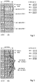
- Fig. 1 shows a resource-scheduling system on a communication channel for systems with e.g. a single shared data channel.
- a transmission time interval (TTI) reflects the smallest interval at which the scheduler (e.g. the Physical Layer or MAC Layer Scheduler) performs the dynamic resource allocation (DRA).
- a TTI equal to one sub-frame (also referred to as a time slot) is assumed. It should be noted that generally a TTI may also span over multiple sub-frames.
- the smallest unit of radio resources (also referred to as a resource block), that can be allocated in OFDMA systems, is typically defined by one TTI in time domain and by one subcarrier/subband in the frequency domain.
- this smallest unit of radio resources is defined by a TTI in the time domain and a code in the code domain.
- this smallest unit is defined by one TTI in time domain, by one subcarrier/subband in the frequency domain and one code in the code domain. Note that dynamic resource allocation may be performed in time domain and in code/frequency domain.
- TDS time domain scheduling
- DPA dynamic user rate adaptation
- the scheduler can assign available resources (codes in case of CDMA, subcarriers/subbands in case of OFDMA) to users having good channel conditions in time domain scheduling.
- Time Domain Scheduling TDS
- Frequency Domain Scheduling FDS
- TDS Time Domain Scheduling
- FDS Frequency Domain Scheduling
- the OFDM signal is constructed out of multiple narrowband subcarriers (typically grouped into subbands) in frequency domain, which can be assigned dynamically to different users.
- the frequency selective channel properties due to multi-path propagation can be exploited to schedule users on frequencies (subcarriers/subbands) on which they have a good channel quality (multi-user diversity in frequency domain).
- the bandwidth is divided into multiple subbands for practical reasons that consist out of multiple subcarriers.
- the smallest unit on which a user may be allocated would have a bandwidth of one subband and a duration of one sub-frame (which may correspond to one or multiple OFDM symbols), which is denoted as a resource block (RB).
- RB resource block
- a subband consists of consecutive subcarriers.
- a scheduler may also allocate a user over multiple consecutive or non-consecutive subbands and/or sub-frames.
- a 10 MHz system may consist out of 600 subcarriers with a subcarrier spacing of 15 kHz.
- the 600 subcarriers may then be grouped into 24 subbands (a 25 subcarriers), each subband occupying a bandwidth of 375 kHz.
- a resource block RB would span over 375 kHz and 0.5 ms according to this example.
- LM localized mode
- Fig. 2 shows an exemplary data transmission to users in an OFDMA system in localized mode (LM) having a distributed mapping of Layer 1/Layer 2 control signalling.
- the users may be allocated in a distributed mode (DM).
- DM distributed mode
- a user mobile station
- resource blocks which are distributed over a range of resource blocks.
- distributed mode a number of different implementation options are possible.
- a data transmission to users in an OFDMA system in distributed mode (DM) having a distributed mapping of Layer 1/Layer 2 control signalling is shown in Fig. 3 .
- link adaptation is a typical measure to exploit the benefits resulting from dynamic resource allocation.
- AMC Adaptive Modulation and Coding
- MCS modulation and coding scheme
- MCS modulation and coding scheme
- HARQ hybrid ARQ
- CQI Channel Quality Information
- a scheduler assigns transmission resources to several users as has been outlined above. Since generally the channel conditions for different users will vary over at least time and frequency, some sort of channel state or channel quality information is required at the scheduler, preferably transmitted from each user equipment device to the scheduler entity.
- the most accurate channel state information should be for the strongest resource blocks, to optimally assign a resource to a user where the channel exhibits a good quality. This will further be used in case that for transmission of data, the modulation or coding scheme is adapted to the channel quality, to increase the spectral efficiency, i.e. in cases where link adaptation is performed.
- the CQI is transmitted from a transmitting entity to a receiver entity.
- a NodeB may act as the multi-user management entity, as well as a multi-cell management entity
- the CQI for the downlink transmission chain is obtained (estimated) by a user equipment (UE), which subsequently transmits CQI to a NodeB. Therefore with respect to CQI transmission the user equipment acts as the transmitter entity, and the NodeB as the receiver entity.
- a CQI value for each of the N rb resource blocks is transmitted, giving the highest accuracy of information at a very high cost of required transmission bits.
- a system based on the following configurations may be considered: the communication system is equipped with 2x2 MIMO (Multiple Input Multiple Output) using PARC (Per Antenna Rate Control), 20 MHz transmission bandwidth (48 Resource Blocks), 0.5 ms CQI feedback interval, 1/3 rate turbo encoding, no-repetitions or puncturing, and with 24 bit CRC attached.
- the total CQI feedback overhead of this configuration would be 2.904 Mbps per user.
- the "Strongest-M" DCT scheme transmits the DC component of the transformation and in addition M-1 most significant DCT coefficients. Assuming that M is known to transmitter and receiver, only indices of the transmitted coefficients as well as the values of the transmitted coefficients need to be signalled. If M is not known by either the transmitter or the receiver, the value of M may have to be signalled as well.
- the "First-M" DCT scheme transmits the M coefficients with the M lowest index values. Assuming that M is known to transmitter and receiver, only the values of the transmitted coefficients need to be signalled. If M is not known by either the transmitter or the receiver, the value of M may have to be signalled as well.
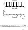
- FIG. 8 An example of a channel snapshot and an exemplary reconstruction of the channel power using "Strongest 5" DCT scheme is shown in Fig. 8 .
- 3GPP RAN WG#1 Tdoc. R1-061819 "Overhead reduction of UL CQI signalling for E-UTRA DL", available at http://www.3gpp.org , discusses a "Best-M” scheme for feedback reduction of channel quality signalling where a UE reports a label which indicates the M resource blocks with highest signal quality and additionally a single channel quality indicator for these resource blocks. Assuming that M is known to the transmitter and the receiver, signalling of the M selected indices and the selected M values is needed in a CQI report.
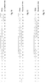
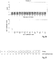
- a further scheme referred to as "Best M Individual” scheme reports the power for each of the M best resource blocks, and average power for other resource blocks. Assuming that M is known to the transmitter and the receiver, signalling of the M selected indices, the selected M values, and the average value is needed in a CQI report. An exemplary bitmap that signals the best 5 out of 24 resource blocks is shown in Fig. 13 .
- a further scheme referred to as "Best M Average” reports the average power for M best resource blocks, and average power for other resource blocks. Assuming that M is known to the transmitter and the receiver, signalling of the M selected indices and the two average values is needed in a CQI report. An exemplary bitmap that signals the best 5 out of 24 resource blocks is shown in Fig. 13 .
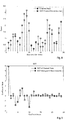
- FIG. 11 An example of a channel snapshot and an exemplary reconstruction of the channel power using a "Best 5 Individual” scheme and a “Best 5 Average” scheme are shown in Fig. 11 and in Fig. 12 , respectively.
- the "Best 5 Individual” scheme manages to give exact information for the 5 strongest resource blocks (number 8, 9, 10, 18, 19), but quite substantial deviations from the correct value for all other resource blocks.
- the "Best 5 Average” scheme gives by chance quite accurate information for resource blocks 18 and 19, while we can identify larger deviations - both better and worse - from the correct value for resource blocks 8, 9, and 10. Likewise, for all other resource blocks the reconstructed value may exhibit large differences from the correct values.
- the full feedback scheme requires a very high amount of bits to signal the CQI. This requirement may be too high to fulfil in a transmission system, particularly in cellular mobile radio systems where a large number of entities have to report CQI values.
- DCT-based schemes do not offer an optimal solution for transmitting the CQI information. Since only a limited number of coefficients is transmitted in a DCT compression scheme, the reconstruction at the receiver (which typically offers scheduling functions) is generally not optimum for any resource block. Consequently there will be deviations for the strongest resource blocks, which will result in erroneous scheduler decisions or suboptimum adaptive modulation and coding decisions by the link adaptation entity. Consequently the spectral efficiency is reduced.
- the information conveyed by the average CQI scheme is of very low accuracy.
- a higher accuracy than that provided by the average scheme has to be available.
- EP1 533 966 A2 discloses a method of transmitting/receiving channel quality information of subcarriers in an OFDM system.
- EP1 633 073 A2 discloses a method of interpolating channel quality in a wireless communication system.
- US 2003/003880 discloses techniques for deriving channel state information indicative of the characteristics of a number of transmission channels used for data transmission.
- One object is to suggest a scheme for transmitting channel quality measures from a transmitter to a receiver that may mitigate at least one of the problems outlined above.
- Another object is to suggest a scheme for communicating channel quality measures that on the one hand allows for an accurate reconstruction of the channel quality measures at the receiver and on the other hand requires an acceptable transmission overhead.
- channel quality feedback measures for a channel are divided into distinct partitions. Each partition consists only of a subset of the channel quality feedback measures.
- the partitioning of the channel quality feedback measures may allow for reducing the amount of overhead that needs to be attributed to the signalling of channel quality information, as (in some examples) the partitioning may be advantageously used to further reduce the amount of signalling information. Further, the partitioning may allow for a more accurate reconstruction of the channel state at the receiver, from which scheduling and link adaptation may benefit.
- a scheduler may utilize the information on the channel condition to schedule air interface resources of transmitters that are served by the scheduler.
- the reconstructed channel estimate may also be employed to determine the link adaptation to be applied to data transmissions on a wireless channel.
- a further example is the use of some (re)ordering scheme that is reordering the channel quality measures prior to their transmission as channel quality information.
- the channel quality measures of a channel may be (re)ordered so that encoding of the measures yields the most accurate reconstruction of the measures at the receiver.
- the (re)ordering mechanism may also be combined with the other examples outlined above.
- a method for transmitting channel quality information in a communication system is provided.
- the channel quality values (e.g. of the plurality of resource units) may be first partitioned into at least two partitions. Then the channel quality values of at least one of the at least two partitions may be transformed to obtain channel quality coefficients. These coefficients may be encoded to obtain signalling information on the channel quality which is signalled to a receiving entity.
- the number of the channel quality coefficients obtained for a respective partition by transformation is equal to the number of the channel quality values of the respective partition.
- the transformation used for transforming of the channel quality values may for example be a discrete cosine transformation (DCT), a Fourier transformation or a transformation based on a continuous function.
- DCT discrete cosine transformation
- Fourier transformation a transformation based on a continuous function.
- Channel quality information may be transmitted in a communication system by first partitioning channel quality values of the plurality of resource units into at least two partitions, encoding the channel quality values to obtain signalling information on the channel quality and signalling the signalling information on the channel quality to a receiving entity.
- the channel quality values may be partitioned by comparing the individual channel quality values to at least one channel quality threshold value.
- one threshold value per boundary of neighbouring partitions may be defined.
- the channel quality values are partitioned by allocating a given number of channel quality values to a respective partition.
- This number of channel quality values in a partition may for example be preconfigured.
- the predefinition of the number of values per partition may for example be advantageous in that no signalling of the number of elements in the partition is necessary.
- the sum of the cardinality of the at least two partitions is equal to the number of channel quality values, i.e. all channel quality values are allocated to either one of the at least two partitions.
- the channel quality coefficients or values may be encoded by compressing the channel quality coefficients or values, respectively, of at least one partition.
- the signalling information on the channel quality may indicate a number of encoded channel quality coefficients or values to the receiving entity that is smaller than the number of the channel quality coefficients or values, respectively, in the at least two partitions.
- the channel quality coefficients or values are encoded by selecting the minimum number of channel quality coefficients or values, respectively, from a partition yielding a power level equal to or higher than a threshold power level.
- the channel quality coefficients or values may be encoded by selecting a subset of the channel quality coefficients or values, respectively, from at least two partitions.
- the cardinality of a first subset of the subsets may depend on the cardinality of a second subset of the subsets.
- At least one combined channel quality coefficient or value derived from at least two channel quality coefficients or values, respectively is determined and that the at least one combined channel quality coefficient or value is encoded. This may for example be useful in order to reduce the signalling overhead by combining all or a subset of channel quality values/coefficients to one or more averaged values/coefficients prior to transmission.
- Another option to encode the channel quality values or coefficients according to another example is to encode same by selecting a predefined number of channel quality coefficients or values, respectively, from the at least two partitions.
- the number of selected channel quality coefficients or values from a first partition of the at least two partitions may for example depend on at least one predetermined constraint, while the remaining number of selected channel quality coefficients or values may be selected from at least the second partition of the at least two partitions.
- the partitions may be encoded according to the same or according to different encoding schemes.
- the channel quality coefficients or values of at least two partitions may be jointly encoded. This may for example be implemented as follows. A respective channel quality coefficient or value in a respective partition may be identified by an index. The channel quality coefficients or values may be jointly encoded by selecting channel quality coefficients or values, respectively, from at least two partitions having the same indices.
- the at least two partitions do not have equal cardinality, it may be beneficial to add padding coefficients or values to a partition so as to obtain at least two partitions having same cardinality.
- a respective channel quality coefficient or value in a respective partition may be indexed.
- averaged channel quality coefficients or values are determined prior to encoding and the averaged channel quality coefficients or values are encoded.
- the averaged channel quality coefficients or values may be determined by a coefficient-wise or value-wise averaging of channel quality coefficients or values, respectively from at least two partitions. Further, it may be foreseen that channel quality coefficients or values, respectively from at least two partitions having the same index are averaged coefficient-wise or value-wise, respectively. This may for example allow for reducing the index signalling overhead.
- the channel quality coefficients or values of at least one partition may be reordered prior to their encoding. For example, reordering is performed according to one of predefined reordering maps or according to one of predefined interleaving schemes.
- a respective channel quality coefficient or value in a respective partition may be identified by an index.
- the signalling information on the channel quality may indicate the indices of the encoded channel quality coefficients or values of a respective partition included in the signalling information on the channel quality.
- the signalling information on the channel quality may further comprise information on the values of the encoded channel quality coefficients or values.
- At least one of the at least two partitions may be partitioned prior to transformation or encoding to obtain at least two sub-partitions.
- This may be useful in situations where for example a first partitioning is performed according to the number of antennas (e.g. one partition of channel quality values per antenna) and then each of the partitions is again divided into sub-partitions (e.g. based on a threshold value).
- the channel quality values in at least one sub-partition may by transformed prior to encoding to obtain channel quality coefficients for a respective sub-partition.
- a receiving entity may receive signalling information on the channel quality from a transmitting entity. This signalling information on the channel quality may be decoded by the receiving entity to obtain channel quality coefficients of at least two partitions. Further, the channel quality coefficients of each partition may be transformed to obtain channel quality values for a respective partition, and the channel quality values may be reconstructed using the channel quality values of at least one partition.
- no (inverse) transformation of channel quality coefficients may be necessary, e.g. due to performing no transformation on the transmitting entity side.
- the channel quality values may be directly derived from the signalling information on the channel.
- the channel quality values of the plurality of resource units may be received from a plurality of transmitting entities.
- the receiver schedules a respective one (at least one) of the plurality of transmitting entities taking into account at least the reconstructed channel quality values signalled by the respective transmitting entity.
- the receiver may select at least one link adaptation parameter for link adaptation for a respective one of the plurality of transmitting entities taking into account at least the reconstructed channel quality values signalled by the respective transmitting entity.
- this at least one link adaptation parameter may be related to at least one of a modulation and coding scheme, a configuration of at least on hybrid automatic repeat request process, and transmission power control.
- a management entity may determine at least one parameter for at least one of partitioning, encoding, or transformation. Moreover, the management entity may convey the at least one parameter to the channel quality information transmitter using a control signal.
- the management entity may be a base station (Node B in the UMTS terminology) or may be another network entity located in the core network or access network of a communication system.
- This transmitter may comprise a processing unit for partitioning channel quality values into at least two partitions.
- the processing may further transform the channel quality values of at least one of the at least two partitions to obtain channel quality coefficients.
- the transmitter may also include a coding unit for encoding the channel quality coefficients to obtain signalling information on the channel quality and a transmitting unit for signalling the signalling information on the channel quality to a receiving entity.
- a further example relates to a transmitter comprising a processing unit for partitioning channel quality values of the plurality of resource units into at least two partitions, and a coding unit for encoding the channel quality values to obtain signalling information on the channel quality.
- the transmitter may comprise a transmitting unit for signalling the signalling information on the channel quality to a receiving entity.
- the transmitter may means to perform the steps of the method for transmitting channel quality information in a communication system according to one of the various examples described herein.
- a receiver for reconstructing channel quality values may comprise a receiving unit for receiving signalling information on the channel quality from a transmitting entity. Further, the receiver may have a decoding unit for decoding the signalling information on the channel quality to obtain channel quality coefficients of at least two partitions, and a processing unit for transforming the channel quality coefficients of each partition to obtain channel quality values for a respective partition. The processing unit may reconstruct the channel quality values using the channel quality values of at least one partition.
- a receiver for reconstructing channel quality values may comprise a receiving unit for receiving signalling information on the channel quality from a transmitting entity, and a decoding unit for decoding the signalling information on the channel quality to obtain channel quality values of at least two partitions.
- the receiver according to this example may comprise a processing unit for reconstructing the channel quality values of a plurality of resource units using the channel quality values of at least one partition.
- the receiver may contain means to perform the steps of the method for reconstructing channel quality values according to one of the various examples described herein.
- Another example relates to a computer-readable medium storing instructions that, when executed by processor of a transmitter, cause the transmitter to transmit channel quality information in a communication system.
- the transmitter may be caused to transmit channel quality information in a communication system by partitioning channel quality values into at least two partitions, transforming the channel quality values of at least one of the at least two partitions to obtain channel quality coefficients, encoding the channel quality coefficients to obtain signalling information on the channel quality and signalling the signalling information on the channel quality to a receiving entity.
- a transmitter may be caused to transmit channel quality information in a communication system by partitioning channel quality values into at least two partitions, encoding the channel quality values to obtain signalling information on the channel quality and signalling the signalling information on the channel quality to a receiving entity.
- a further example relates to a computer-readable medium storing instruction that, when executed by the processor of the transmitter cause the transmitter to perform the steps of the method for transmitting channel quality values according to one of the various examples described herein.
- Another computer-readable medium stores instruction that, when executed by a processor of a receiver, cause the receiver to reconstruct channel quality values.
- the receiver may be caused to reconstruct channel quality values by receiving signalling information on the channel quality from a transmitting entity, decoding the signalling information on the channel quality to obtain channel quality coefficients of at least two partitions, and transforming the channel quality coefficients of each partition to obtain channel quality values for a respective partition, and reconstructing the channel quality values of the plurality of resource units using the channel quality values of at least one partition.
- the receiver may be caused to reconstruct channel quality values by receiving signalling information on the channel quality from a transmitting entity, decoding the signalling information on the channel quality to obtain channel quality values of at least two partitions, and reconstructing the channel quality values of the plurality of resource units by using the channel quality values of at least one partition.
- a further example relates to a computer-readable medium storing instruction that, when executed by the processor of the receiver cause the receiver to perform the steps of the method for receiving channel quality information in a communication system according to one of the various examples described herein.
- the transmitting entity may reorder channel quality values, and may then transform the reordered channel quality values to obtain channel quality coefficients. Further, the channel quality coefficients may be encoded to obtain signalling information on the channel quality which may be signalled to a receiving entity.
- the reordering comprises determining a number of sequences of reordered channel quality values by employing different reordering mappings.
- the transmitting entity may choose a reordering mapping for which the reordered channel quality values fulfil an optimality criterion prior or after transformation.
- the reordering scheme is signalled to the receiving entity, for example, within the channel quality information.
- the reordering mappings are defined by at least one reordering parameter.
- a further example relates to a method for reconstructing channel quality values.
- a receiving entity may first receive signalling information on the channel quality from a transmitting entity and may decode the signalling information on the channel quality to obtain channel quality coefficients.
- the receiving entity may transform the channel quality coefficients, and reconstruct channel quality values by reordering the transformed channel quality coefficients.
- the transformed channel quality coefficients are reordered according to a mapping scheme.
- the mapping scheme may for example be indicated within the channel quality information or in control signalling received by the receiving entity.
- the transmitter comprises a reordering unit for reordering channel quality values, and a processing unit for transforming the reordered channel quality values to obtain channel quality coefficients. Further, a coding unit of the transmitter may encode the channel quality coefficients to obtain signalling information on the channel quality and a transmission unit may signal the signalling information on the channel quality to a receiving entity.
- the receiver may include a receiving unit for receiving signalling information on the channel quality from a transmitter, and further a decoding unit for decoding the signalling information on the channel quality to obtain channel quality coefficients.
- the receiver may also comprise a processing unit for transforming the channel quality coefficients, and a reordering unit for reconstructing channel quality values by reordering the transformed channel quality coefficients.
- Another example relates to a computer readable medium storing instruction that, when executed by a processor of a transmitter, cause the transmitter to transmit channel quality information in a communication system, by reordering channel quality values, transforming the reordered channel quality values to obtain channel quality coefficients, encoding the channel quality coefficients to obtain signalling information on the channel quality and signalling the signalling information on the channel quality to a receiving entity.
- a further example relates to a computer readable medium storing instruction that, when executed by a processor of a receiver, cause the receiver to transmit channel quality information in a communication system, by receiving signalling information on the channel quality from a transmitter, decoding the signalling information on the channel quality to obtain channel quality coefficients, transforming the channel quality coefficients, and reconstructing channel quality values by reordering the transformed channel quality coefficients
- N rb denotes the total number of resource unit of a channel
- v ⁇ or ⁇ i j denotes a channel quality value i for resource unit i
- i 1,..., N RB
- j may indicate the partition P j to which the channel quality value has been assigned
- j may indicate the transformed partition T j of the channel quality coefficient
- compression refers to a channel quality information provision scheme, where the total channel quality information feedback overhead is reduced compared to the "Full Feedback” case described in the Technical Background section.
- resource unit refers to one of a plurality of resource units of a channel for which a channel quality measure is obtained. Channel quality reporting may thus be performed on a per-resource unit basis.
- this resource unit may or may not be equal to a resource block denoting the smallest amount of resources of a channel that can be allocated to a user (e.g. by scheduling).
- a resource unit could refer to a resource of one subframe in the time domain and a subband in the frequency domain, while a resource block denotes a subframe in the time domain and a subcarrier (of one of the subbands) in the frequency domain.
- a resource unit refers to a range of time or frequencies (subcarriers) - in time or frequency domain - over which the channel state is substantially flat, e.g. a coherence time or coherence bandwidth, which may or may not be a multiple of the respective smallest amount of resources in the communication system (e.g. resource block, subframe, TTI).
- the example relates to the communication of information on the state of a channel between a transmitting entity and a receiving entity, such as for example a mobile station and a base station in a mobile communication system.
- a resource management entity preferably has some sort of channel state information available for the link between base station and mobile station ("downlink") as well as for the link between mobile station and base station ("uplink"). Assuming that this resource management entity is located within the base station or farther towards the network side, the channel state information for the downlink may have to be measured by the mobile station and then be transmitted via the uplink to the base station to the resource management entity.
- the channel state information for the uplink may have to be measured by the base station and then be transmitted via the downlink to the mobile station to the resource management entity.
- the channel state measures (or channel quality values) are provided or measured for each resource unit into which the communication channel between transmitting entity and receiving entity is divided.
- One example is to divide the channel state measures into distinct partitions - in case of having a channel quality measure per resource unit this can also be viewed as a partitioning of the resource units. Each partition consists only of a subset of the channel state measures.
- the partitioning of the channel quality feedback measures may allow for reducing the amount of overhead that needs to be attributed to the signalling of channel quality information, as (in some examples) the portioning may be advantageously used to further reduce the amount of signalling information. Further, the partitioning of the channel quality measures may allow for a more accurate reconstruction of the channel state at the receiver.
- a scheduler may utilize the information on the channel condition to schedule air interface resources of transmitters that are served by the scheduler.
- the reconstructed channel estimate may also be employed to determine the link adaptation to be applied to data transmissions on a wireless channel.
- a further example is the use of some sort of (re)ordering scheme that is reordering the channel quality measures prior to their transmission as channel quality information.
- the reordering of the channel quality measures may be obtained by an interleaving algorithm.
- the channel quality measures of a channel may be (re)ordered so that encoding of the measures yields the most accurate reconstruction of the measures at the receiver.
- the (re)ordering prior to the transformation may be chosen so as to concentrate most power of the channel quality measures in a number of coefficients that can be transmitted according to the encoding scheme.
- the (re)ordering mechanism may be combined with the other examples as will be outlined in further detail in the following.
- the channel quality may be periodically measured or determined by a reporting terminal. Generally, this may for example be implemented by measuring the channel quality for each of a plurality of resource units into which the communication channel to report on is (logically) divided at the reporting terminal to obtain a set of channel quality values or measures (e.g. power values).
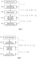
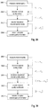
- Fig. 4 shows a flow chart of a method for transmitting channel quality information according to an example.
- the transmitting entity may determine 401 the channel quality measures of the channel. This may for example be accomplished by measuring a channel quality value for each resource unit of the channel on which the transmitting entity is reporting. An exemplary channel snapshot obtained by the measurement is shown in Fig. 14 .
- the channel on which is to be reported is divided into 24 resource units for which individual channel quality measures are determined.
- 24 channel quality values v 1 ,..., v 24 are obtained.
- Each resource unit i.e. its channel quality measure may be assigned unambiguously to exactly one partition.
- the partitions may for example be defined such that resource units with similar channel quality measures (e.g. power values) are contained in the same partition.
- resource units having the strongest channel quality values are contained in a first partition, and other resource units are contained within a second partition.
- the partition creation is depending on e.g. on one or more partition threshold values.
- Fig. 14 shows an example of the partition threshold to define a first and a second partition, each of which contains only resource units whose SINR is either above or below the threshold value, respectively. It is a matter of convention whether resource units that have SINR values equal to the threshold should go into the first or into the second partition.
- the partitions are each of cardinality smaller than that of the original sequence. Without loss of generality, it may be assumed that the number of elements in the first partition N 1 is smaller than or equal to the number of resource units in the original sequence N rb .
- the channel quality values of the resource units are ordered in the same way as is the original sequence. Therefore following the example of Fig. 14 , the first partition P 1 should consist of the channel quality values with the indices 8, 9, 10, 18, 19 (i.e. ⁇ 8 1 , ⁇ 9 1 , ⁇ 10 1 , ⁇ 18 1 , ⁇ 19 1 ) of the original sequence in that order, while the second partition should consist of the channel quality values with the indices 1-7, 11-17, 20-24 of the original sequence (i.e. ⁇ 1 2 , ... , ⁇ 7 2 , ⁇ 11 2 , ... , ⁇ 17 2 , ⁇ 20 2 , ... , ⁇ 24 2 ) in that order.
- the partitioning (partition affiliation) of the channel quality measures may be represented by a bitmap as illustrated in Fig. 15 , where the partition to which a respective channel quality measure is assigned is indicated by a single bit. Obviously, more bits per channel quality measure are needed if more than two partitions are formed (e.g. ⁇ ld(n) ⁇ bits for n partitions).
- a partition threshold is used to divide the 24 channel quality measures into two partitions.
- a next step 403 the channel quality values in at least one of the two created partitions are transformed.
- a discrete cosine transform for each partition ( P 1 and P 2 ) is performed. Details on a DCT as may be used by in an example may be found in Ahmed, N., Natarajan T. and Rao K. R., "Discrete Cosine Transform", IEEE Trans. Computers, January 1974 .
- the transformed partitions T 1 and T 2 are obtained.
- the DCT does not change the number of elements in a set, i.e. the cardinality of the transform is equal to the cardinality of the source. Consequently in the example of Fig. 14 , Fig. 16 and Fig. 17 , the DCT of the first partition T 1 contains five elements, while the DCT of the second partition T 2 contains nineteen elements, as visualized in Fig. 16 and Fig. 17 .
- step 404 the channel quality coefficients obtained by the transformation in step 403 are encoded. In one example, this may be accomplished by performing a compression of the coefficients for each transformed partition T i separately.
- each transformed partition only certain DCT coefficients are selected for feedback transmission.
- compression may take the coefficients of at least two transformed partitions into account.
- the total number of DCT coefficients to be transmitted after compression e.g. the sum M 1 + M 2 for two partitions
- compression may take the number of available bits for channel quality information transmission of at least two transformed partitions into account.
- the total number of available bits for the channel quality information transmission compression after compression is a (pre)determined or preconfigured value.
- the number of transmitted DCT coefficients after compression per partition may then be determined taking the required signalling for at least two partitions into account, plus the necessary amount of bits for partition affiliation or coefficient index signalling, if required.
- a similar approach may also be used when "directly" compressing the channel quality values, i.e. when not performing a transformation of the partition(s).
- the mobile terminal may determine how many DCT coefficients from each transformed partition are selected for transmission and under which constraint(s) the selection is performed. If, for example, the values within a transformed partition are constant or nearly constant, then one or two DCT coefficients are sufficient for reconstruction at the receiver. Consequently the mobile station may transmit more DCT coefficients of another partition that shows greater fluctuations in its DCT coefficients.
- the transmitter e.g. the mobile station
- the transmitter may deliberate within the above constraints, depending on the actual channel conditions, how to use the available number of coefficients or bits to convey the optimum accuracy to the receiving entity.
- the constraints could be further defined to require a minimum number of coefficients for a given partition, limiting the degree of freedom of the mobile terminal. This method may however require additional signalling of the selected coefficients from the mobile station to the receiving entity.
- the remaining coefficients may be employed to select an appropriate number of coefficients from the second partition T 2 .
- constraints like those mentioned above (e.g. minimum number of selected coefficients per partition) may further reduce the degree of freedom.
- the DCT coefficients for the first partition T 1 according to Fig. 16 respectively contain 98.07%, 0.41%, 0.02%, 0.5%, and 1% of the total power. Consequently to capture more than 99% of the power, the selection of coefficients 1 and 5 (i.e. c 1 1 and c 5 1 ) of partition T 1 may be sufficient. Assuming that a total number of 6 coefficients can be selected for transmission in the encoding procedure 404, the remaining 4 coefficients can then be selected from the second partition (see Fig. 17 ). To save signalling for the second partition, the first four coefficients of the second partition T 2 may be selected by default. For higher accuracy, the four strongest coefficients of partition T 2 may be selected. In this fashion, coefficients 1, 3, 10, and 11 (i.e. c 1 2 , c 3 2 , c 10 2 and c 11 2 ) may be selected in the example. These coefficients contain almost 88% of the power of partition T 2 .
- the power contained in the selection for partition T 1 is 99.57% (i.e. a gain of 0.5%), while for partition T 2 it is only roughly 85.38% (i.e. a loss of about 2.5%) given that three strongest coefficients from each partition are chosen.
- the power contained in the selection for partition T 1 is 99.57% (i.e. a gain of 0.5%), while for partition T 2 it is only roughly 85.38% (i.e. a loss of about 2.5%) given that three strongest coefficients from each partition are chosen.
- those skilled in the art will be able to select the most suited coefficients from the partitions as needed.
- step 405 the selected channel quality coefficients from the partitions are transmitted as channel quality information to the receiving entity.
- the partitioning partition affiliation
- Fig. 5 shows another exemplary flow chart of a method for transmitting channel quality information according to an example.
- the flow chart shown in Fig. 5 is similar to same in Fig. 4 .
- the channel quality information transmission scheme shown in Fig. 5 does not include a transformation of the partitions P 1 and P 2 prior to encoding. Instead, the channel quality values v i of the respective partitions may be directly encoded 501 using similar mechanisms as described with respect to Fig. 4 above and are subsequently transmitted 502 as channel quality information to the receiver.
- Fig 6 shows an exemplary flow chart of a method for receiving and reconstructing channel quality values for channel quality information according to an example.
- Fig. 6 essentially mirrors the steps of Fig. 4 at the receiving entity.
- the channel quality information provided by a transmitter e.g. a mobile station
- the channel quality information may then be decoded 602. This means that the channel quality coefficient values (and optionally the indices for the signalled channel quality coefficient values) in the channel quality information are used to first reconstruct the channel quality coefficients that have been selected by the transmitter for transmission in terms of their values and position.
- partitions T i may be reconstructed 603 based on the partitioning pattern (partition affiliation) in the channel quality information received from the transmitter. Thereby the respective coefficients in the partitions may be either set according to the signalled coefficient values or to zero (or a predetermined value) if a coefficient value is not signalled in the channel quality information.
- the partitions T i same may be transformed 604 to reconstruct partitions P i of channel quality values.
- the partitions P i of channel quality values are subsequently combined to reconstruct the set of channel quality measures v 1 ,..., v 24 at the receiver for the plurality of resource units.
- Fig. 7 shows another exemplary flow chart of a method for receiving and reconstructing channel quality values for channel quality information according to an example. Essentially, the individual steps shown in Fig. 7 are similar to those shown in Fig. 6 . However, as in Fig. 5 , it is assumed that the channel quality values of the partitions P i are directly encoded and transmitted to the receiver. Hence, upon the reception of the partitions P i of channel quality values may be directly reconstructed 702 from the channel quality information by a decoder in step 701.
- Fig. 20 shows the channel state as in Fig. 14 and a reconstruction of channel quality values from compressed partition-wise DCT according to an example.
- Partitioning the channel quality values shown in the upper part of Fig. 22 into two partitions in this example allows for having a more regular distribution of channel quality values in each of two partitions. Comparing the exemplary original sequence of channel quality values as in Fig. 22 , two partitions may be created that comprise channel quality values of resource units with values of 4 and 1, respectively. Consequently the first partition contains only elements of having a channel quality value equal to 4 as shown in Fig. 24 upper part (i.e.
- the second partition contains only elements having a channel quality value equal to 1 as shown in Fig. 26 upper part (i.e. elements v 1 , v 3 , v 5 , v 7 , v 10 , v 12 , v 14 , v 16 , v 17 , v 19 , v 20 , v 22 to v 24 of the original sequence).
- the partitioning may either be achieved by defining that the first partition should contain 10 elements and the second partition 14 elements, or a partition threshold of a value between 1 and 4 may have been defined.
- the distribution of channel quality values in each of the partitions is more regular in comparison to the original sequence shown in Fig. 22 . Due to this more regular distribution of the channel quality values in the two partitions (in this example a uniform distribution is obtained), the power of the DCT coefficients of each of the two partitions shown in Fig. 24 and Fig. 26 in the lower part, respectively, may be concentrated in the first coefficients of the DCT transform. In this example, due to the uniform distribution of the values in each partition, the total power of the channel quality values of a partition concentrates in the DC component of the DCT transform as can be also seen from the bitmaps indicating the strongest coefficients shown in Fig. 25 and 27 respectively.
- This effect allows in turn reducing the number of coefficients that need to be transmitted.
- it is sufficient to transmit the value of the DC component of the DCT transform (i.e. the first coefficient) of each partition as well as information on the partitioning (partition affiliation) of the values/coefficients (and optionally the index of the transmitted DC component in the respective partition) to allow for an ideal reconstruction of the original sequence of the channel quality values of Fig. 22 at the receiver.
- the overhead for transmitting these channel quality information to the receiver may be less than in prior-art schemes.
- each partition may employ a compression scheme independently from any other partition.
- a first partition may be compressed employing the discrete cosine transform, while another partition may be compressed using a Daubechies wavelet. From an implementation aspect however, it may be advantageous to employ the same compression approach in all partitions, so as to minimize the hardware or software efforts necessary.
- transform or encoding schemes or parameters for at least one partition may vary over time.
- An option to determine the transform or encoding scheme or parameters for at least one partition may take the channel quality information reporting frequency into account. For example, if channel quality information reporting occurs infrequently (e.g. at a rate below a threshold frequency), it may be advantageous to transmit a large number of values/coefficients to allow very detailed reconstruction, or alternatively to choose an encoding scheme that offers a high amount of accuracy such as "DCT Strongest M" or "Best M Individual".
- each channel quality information signal may preferably be rather small, so as to keep the overall required amount of signalling small. This may result in the choice of a few number of values/coefficients or in the choice of a quite coarse encoding scheme like "Average”, “Best M Average”, or "DCT First M".
- a first transform or first encoding scheme or first set of channel quality information transmission parameters (such as number of transmitted values/coefficients, number of partitions, number of values in a partition, partition threshold values etc.) is used.
- a second transform or second encoding scheme or second set of channel quality information transmission parameters is used for channel quality information reports between two such channel quality information reports.
- the transmitter may decide to transmit a large number of values/coefficients to allow very detailed reconstruction, or alternatively to choose an encoding scheme that offers a high amount of accuracy.
- FIG. 29 and Fig. 30 show exemplary flow charts of a method for transmitting channel quality information using (re)ordering mechanisms according to different examples. While the example shown in Fig. 29 does not employ partitioning and transforming the channel quality values, the example shown in Fig. 30 further includes steps to transform the (re)ordered channel quality values prior to transmission. It should be noted that in both examples, also a partitioning of the channel quality values prior to or after (re)ordering may be foreseen.
- the channel quality values v 1 ,..., v N rb indicative of the channel quality may be either first measured 2901 or may be available at the transmitter.
- the channel quality values may be (re)ordered 2902 to obtain a sequence of (re)ordered channel quality values v ' 1 ,,..., v ' N rb .
- the (re)ordered channel quality values are encoded 2903 using one of the compression schemes described herein. In the example shown in Fig.
- the (re)ordered values may be transformed 3001 for example using a DCT transformation as explained above first and are subsequently encoded 3002 using one of the compression schemes described herein.
- the resulting channel quality information is subsequently reported 2904, 3003 to the receiver.
- the reordering in step 2902 may be done according to various different mechanisms. For example, a known (re)ordering mechanism may be applied that is also known to the receiver. This would obviously require no additional signalling overhead.
- a limited number N r of (re)ordering mappings are determined for example by means of applying interleaving scheme(s) in a trial-and-error fashion.
- the transmitter may obtains the reordered sequences of channel quality values using each of the defined (re)ordering algorithms prior to transformation, thus obtaining N r reordered sequences.
- the transmitter may choose one (re)ordered sequence for transmission (e.g. after transformation and selection of the coefficients/values) that fulfils a certain optimality criterion.
- Such an optimality criterion may for example be the maximum amount of power contained in the first M coefficients or values in the reordered partition.
- Another optimality criterion may be the mean square error between the reconstructed sequence of channel quality values and the (measured) original sequence of channel quality values. This criterion would however imply higher transmitter complexity, as the transmitter may need to reconstruct the sequence to determine the mean squared error for choosing the optimum (re)ordering scheme or parameters. This operation of the transmitter may also be considered an iteration of testing the resulting compressed information against an optimality criterion as described above.
- the (re)ordering signalling merely needs to indicate which out of the N r defined (re)ordering schemes has been selected. This may only require ⁇ ld ( N rb ) ⁇ bits for the (re)ordering signal.
- Another option would be to define the (re)ordering mapping by at least one reordering parameter and to vary this parameter(s), for example within a given range of parameter values, so as to obtain the (re)ordering fulfilling a certain optimality criterion.
- only the at least one reordering parameter may be signalled. This may for example realised in a fashion similar to that outlined below for the signalling of the partitioning and coefficients.
- the (re)ordering may be applied to the channel quality values before transformation of values to coefficients, or it may be applied to the channel quality coefficients obtained after transformation of the channel quality values.
- the order of functional blocks 2902 and 3001 may be exchanged. Either way the optimality criterion is preferably tested after both the (re)ordering and transformation have been applied.
- the (re)ordering of the channel quality values may also be employed together with the concept of partitioning.
- the channel quality values may be (re)ordered prior to their partitioning.
- the values or coefficients within a partition may be reordered prior to their transformation or encoding, respectively. This may be particularly beneficial if a compression scheme is employed that is most accurate for small data indices.
- a further advantage of reordering the channel quality values in a partition may be that the reordering allows achieving a more regular distribution of channel quality values in a partition, which in turn yields that most power of the reordered partition values may be found in only a very low number of coefficients of the DCT transform.
- the reordering is performed such that the reordered partition has a more regular distribution of channel quality values than the original partition prior to reordering.
- the (re)ordering may be for example a sorting or shifting of channel quality values in a partition.
- the method of (re)ordering may be in some way known to the receiver e.g. by signalling or convention.
- the (re)ordering of the data may be signalled to the receiver as well in the channel quality information, unless the (re)ordering algorithm is known a-priori (e.g. using a fixed permutation pattern) to both the transmitter and the receiver. Allowing for an arbitrary (re)ordering may impose heavy demands on the amount of bits that need to be signalled to indicate the reordering applied to the data.
- one out of a limited number N r of (re)ordering mappings (e.g. using interleavers) that are employed by the transmitter is determined (e.g. in a trial-and-error fashion).
- the transmitter may obtain data reordered partitions using each of the defined (re)ordering algorithms prior to transformation, thus obtaining N r reordered partitions.
- the reordered partition may be chosen for transmission (after compression of the coefficients/values) that fulfils a certain optimality criterion.
- such an optimality criterion could be the maximum amount of power contained in the first M coefficients or values in the reordered partition.
- the (re)ordering signalling merely needs to indicate which out of the N r defined (re)ordering schemes has been selected. This may only require ⁇ ld ( N rb ) ⁇ bits for the (re)ordering signal.
- Another optimality criterion may be the minimal variance or minimum mean square error when comparing the original channel quality values with the reconstructed channel quality values from the reordered partition.
- the (re)ordering signalling merely needs to indicate which out of the N r defined (re)ordering schemes has been selected. This may only require ⁇ ld ( N rb ) ⁇ bits for the (re)ordering signal.
- an interleaver or (re)ordering algorithm is used to generate a number of N r interleaver or (re)ordering realisations by using at least one variable interleaver or (re)ordering parameter.
- the particular choice which out of the N r interleaver or (re)ordering realisations is employed by the transmitter to transmit the channel quality information is determined e.g. in a trial-and-error fashion according to an optimality criterion as above, mutatis mutandis.
- the transmitter merely needs to indicate the at least one employed interleaver or (re)ordering parameter value for the selected interleaver or (re)ordering mapping indicating the permutation/interleaving of the input sequence.
- the transmitter merely needs to indicate which out of the N r generated realisations has been selected.
- the (re)ordering approach may for example be particularly advantageous if a "First-M DCT" scheme or similar low-index compression schemes is employed to encode the channel quality values of a partition.
- a partitioning according to the channel quality values on a resource unit basis has been used.
- other classifications can also be used to create the partitions.
- the partitioning is based upon what modulation and coding scheme may be supported by a resource unit at a given target error rate.
- the partitioning is based on the variation of the channel within a resource unit, such that resource units with nearly constant channel are grouped in one partition, and resource units with a fluctuating channel are grouped in a second partition.
- a combination of classification criteria mentioned is used to create the partitions.
- the partitioning may further be determined over each or a combination of the following dimensions:
- the indices of the signalled coefficients or values may be signalled in the following fashions:
- bits may be saved additionally, as the number of required bits may then be calculated as D ⁇ M 1 + M 2 + ⁇ ld N rb M 0 + ld M 0 ⁇ 1 M 1 ⁇ 1 + ld N rb ⁇ M 0 ⁇ 1 M 2 ⁇ 1 ⁇
- the signalling of the value/coefficient indices typically makes up a non-negligible part of the required signalling. Therefore it may be advantageous to use only a single value/coefficient index signal field that is valid for more than one partition.
- the choice of what coefficients are transmitted may be based on any partition.
- the coefficients are chosen so as to represent the strongest coefficients in the partition representing the strongest resource units.
- the choice of coefficients is based upon the coefficient-wise average magnitude of at least two partitions.
- a coefficient for a non-existent index in a partition may be set to a "virtual" zero for the purposes of reduced signalling. For example, if coefficient c 10 had been chosen for transmission of both partitions, the value transmitted for partition T 1 should be zero, as the transform for partition one contains only 5 coefficients. Likewise if averaging is used according to one of the mentioned examples, a coefficient for a non-existent index in a partition may be set to a "virtual" zero for the purposes of determining the coefficient-wise average magnitude of at least two partitions.
- Fig. 21 illustrates the channel state as in Fig. 14 and a reconstruction of channel quality values from compressed partition-wise DCT with reduced coefficient signalling overhead according to an example.
- the reconstruction of the channel quality values based on a reduced amount of channel quality information shows larger deviations from the true channel than the reconstruction including the full partition coefficient signalling. However the saving in signalling information may justify this loss.
- Table 2 illustrates the channel quality values of the channel as well as the reconstructed channel quality values using an encoding scheme as suggested with respect to Fig. 14 , Fig. 16 and Fig. 17 as well as the reconstructed channel quality values using an encoding scheme as suggested with respect to Fig. 14 , Fig. 16 and Fig. 17 and in addition reducing the signalling information further, by signalling the coefficients of partition T 2 , the coefficients at the same indices may be chosen for transmission for partition T 1 , i.e. coefficients c 1 2 , c 4 2 , and c 5 2 as discussed above. A graph of the numerical values is shown in Fig. 20 and Fig. 21 respectively.
- both compression schemes allow for a very accurate reconstruction of the channel quality values for the strongest coefficients of the real channel state.
- the suboptimum choice of the channel quality coefficients for signalling for the second partition in the reduced signalling scheme in the right column is mainly reflected in the less accurate reconstruction of channel quality values of low power (e.g. for indices 11 to 17).
- these low power measures are typically less relevant, as same should be not chosen for data transmission by the respective transmitter (i.e. should not be assigned to the terminal for transmission).
- the channel quality value mentioned herein may be each of or a combination of the following parameters, measures, or values:
- a strong Signal-to-Interference ratio may also be expressed as a modulation scheme indicator that indicates a high-order modulation scheme (e.g. 16-QAM, 64-QAM, etc.), or as a coding scheme indicator that indicates a weak coding scheme (e.g. by a high coding rate), and so forth.
- a modulation scheme indicator indicates a high-order modulation scheme (e.g. 16-QAM, 64-QAM, etc.)
- a coding scheme indicator that indicates a weak coding scheme (e.g. by a high coding rate)
- a channel quality value may be determined over each or a combination of the following dimensions:
- N rb data resources are available in frequency domain. Therefore also the channel quality measure may be obtained as a frequency-domain variable of N rb values.
- a first partition may consequently contain those frequency resource blocks with the M 1 strongest channel quality measures, while a second partition contains the remaining M 2 channel quality measures. It may be noted that this approach may also be used in the special case of OFDM(A), as it can be seen as a special instance of an FDM(A) transmission.
- the channel quality value may vary from one antenna to the other.
- the communication system will generally consist of N MIMO MIMO data streams, for each of which a plurality of channel quality measures may be obtained if e.g. each stream uses an FDM transmission scheme. Consequently a first partition may contain the channel quality measures valid for a first MIMO data stream, while a second partition may contain the channel quality measures for a second MIMO data stream.
- not only the original sequence of channel quality values may be partitioned, but also the resulting partitions may be again divided into subpartitions.
- a first partitioning is made to create partitions A i .
- the data from at least one of said partitions A i is further partitioned to create partitions B i,j .
- i denotes the index of the parent partition
- j denotes the index of the child partition belonging to parent partition i .
- Compression may be employed in any of the parent or child partitions according to any of the methods outlined in the present invention. This may be used to further increase the granularity and accuracy of the compression and reconstruction.
- a first partition A 1 may contain the channel quality measures valid for a first MIMO data stream
- a second partition A 2 may contain the channel quality measures for a second MIMO data stream.
- a first subpartition B 1,1 may contain the strongest channel quality measures contained in partition A 1
- a second subpartition B 1,2 may contain the remaining channel quality measures contained in partition A 1 . This can be applied mutatis mutandis to partition A 2 and subpartitions B 2,1 and B 2,2 .
- the encoded and/or compressed data of all partitions may be transmitted at the same time.
- other solutions may be possible, as outlined in the following.
- a partition-wise successive (serial) transmission of the encoded channel quality information is possible.
- the channel quality information for a first partition is transmitted.
- the channel quality information for a second partition is transmitted.
- the order may be predetermined, signalled, or determined according to e.g. a deviation criterion: channel quality information is transmitted for that partition, for which there occurs the biggest change compared to the previous transmitted compressed data for that partition.
- a successive (serial) transmission of the encoded channel quality information components is used.
- a first coefficient of the channel quality information is transmitted.
- a second coefficient of the channel quality information is transmitted. This may be employed partition-wise (i.e. the coefficients for a first partition are transmitted before the coefficients for a second partition), or in a round-robin or similar fashion (i.e. a first coefficient is transmitted for a first partition, followed by a first coefficient for a second partition, followed by a second coefficient for the first partition, etc.).
- Another option is the use of a successive (serial) transmission of the encoded channel quality information components.
- the partition affiliation signal is transmitted, while the value/coefficient signal for the at least one partition is transmitted at an at least second time instance.
- a further option is to update channel quality information.
- only the difference of the channel quality information for a partition between a first transmission instance and a second transmission instance is transmitted. Said difference may either refer to the transmitted channel quality information at said first transmission instance, or refer to the combination of several previously compressed data transmission instances.
- Another option to transmit the encoded channel quality information may be a partition-wise update/ transmission interval.
- the channel quality information is transmitted using a first update/transmission interval.
- the channel quality information is transmitted using a second update/transmission interval.
- the first update/transmission interval is shorter than the second update/transmission interval.
- time domain can be easily extended or changed to frequency domain, code domain, antenna domain, polarization domain etc. mutatis mutandis.
- the mobile communication system may have a "two node architecture" consisting of at least one Access and Core Gateway (ACGW) and Node Bs.
- the ACGW may handle core network functions, such as routing calls and data connections to external networks, and it may also implement some RAN functions.
- the ACGW may be considered as to combine functions performed by GGSN and SGSN in today's 3G networks and RAN functions as for example radio resource control (RRC), header compression, ciphering/integrity protection and outer ARQ.
- RRC radio resource control
- the Node Bs may handle functions as for example segmentation/concatenation, scheduling and allocation of resources, multiplexing and physical layer functions.
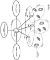
- the NodeBs are illustrated to control only one radio cell.
- the NodeBs may also control several radio cells or logical radio cells.
- a MIMO transmission scheme may be utilized in the communication with the different mobile stations or terminals.
- a shared data channel may be used for communication on uplink and/or downlink on the air interface between mobile stations (UEs) and base stations (NodeBs).
- This shared data channel may have a structure as shown in Fig. 1 and/or may be viewed as a concatenation of subframes as exemplarily illustrated in Fig. 2 or Fig. 3 .
- the shared data channel may be defined as in the Technological Background section herein or as in 3GPP TR 25.814, available at http://www.3gpp.org .
- the information on the channel state may be used to communicate a "snapshot" of the channel quality at a given time instance or over a time interval. If information on the channel state should be used for scheduling or link adaptation, a short report interval may be advantageous. However, even if the report interval of the channel state information is not minimal, the receiver could utilize the information on the channel state in the past for the prediction of a future channel state, which may allow for an adequate scheduling and/or link adaptation.
- the receiver (e.g. Node B in Fig. 28 ) of the information on the channel state may also comprise a scheduling for scheduling the mobile stations and/or a link adaptation entity for performing link adaptation on the communication channel.
- the mobile terminals served by a base station i.e the receiver in this example
- the transmitted channel quality information may need to be protected against errors.
- error detection coding e.g. CRC checksum
- forward error correction Convolutional code, turbo code, Reed-Solomon code
- ARQ automatic repeat requests
- any parameter used to control one or more aspects of the partitioning, transformation or encoding may be determined by a network management entity, e.g. a NodeB.
- the respective control parameters may be signalled from the network to the channel quality information transmitter (e.g. a mobile station) using control signalling, e.g. Layer 1 / Layer 2 (L1/L2) control signals on a L1/L2 control channel, control information in a MAC header, or using RRC signalling.
- the frequency of such L1/L2 control signalling for CQI parameters may be periodic or event-driven.
- the frequency of the control signalling may be determined by a management entity. It may be additionally advantageous to convey different control parameters using control signalling in different resources, e.g. using resources that differ in at least one of:
- any event mentioned previously or hereafter that may cause the transmitter to decide to change one or more channel quality information parameters may as well or instead cause the management entity to decide a change of parameter(s) mutatis mutandis.
- the management entity may as well or instead cause the management entity to decide a change of parameter(s) mutatis mutandis.
- same may be conveyed to the channel quality information transmitter using e.g. a control signal, as outlined in the previous paragraph.
- the scheduling and link adaptation are performed on resource unit basis.
- the smallest unit of (radio) resources also referred to as a resource block or resource unit
- this smallest unit of radio resources is defined by a sub-frame in the time domain and a code in the code domain.
- a resource unit (for scheduling may) be defined as a unit formed by a combination of at least two out of a sub-frame in the time domain, a subcarrier/subband in the frequency domain, a code in the code domain and antenna in MIMO.
- the channel state/quality is reported for a set of resource units into which the channel may be divided. These resource units may or may not be similar to the resource units based on which the mobile stations are scheduled and/or based on which link adaptation may be performed. For example, assuming an OFDM shared channel, the resource units for which the channel state is reported may either correspond to the resource blocks based on which scheduling and/or link adaptation is performed. Alternatively, the transmitting entity (mobile stations) providing the channel state information may also report the channel state on a resource unit-basis where the resource unit is equivalent to one or more subframes in the time domain and one or more subcarrier/subband in the frequency domain. This principle may also be extended to the code domain. In other words, it is not prerequisite that the granularity of the channel state report is identical to the granularity in which resource may be scheduled in the system and/or link adaptation is performed.
- a MC-CDMA scheme or an OFDM scheme with pulse shaping may be used.
- the scheduler may schedule the resources on a per-resource block basis (i.e. per sub-frame basis in the time domain) or on a transmission time interval (TTI) basis, wherein in the latter case it may be assumed that a TTI comprises one or more sub-frames in the time domain.
- TTI transmission time interval
- channel quality information is reported for a channel having 10 MHz bandwidth and consisting out of 600 subcarriers with a subcarrier spacing of 15 kHz.
- the 600 subcarriers may then be grouped into 24 subbands (each containing 25 subcarriers), each subband occupying a bandwidth of 375 kHz. Assuming, that a sub-frame has a duration of 0.5 ms, a resource block (RB) spans over 375 kHz and 0.5 ms.
- RB resource block
- a subband may consist of 12 subcarriers, 50 of those subbands constituting the available 600 subcarriers.
- TTI transmission time interval
- RB resource block
- a computing device or processor may for example be general purpose processors, digital signal processors (DSP), application specific integrated circuits (ASIC), field programmable gate arrays (FPGA) or other programmable logic devices, etc.
- DSP digital signal processors
- ASIC application specific integrated circuits
- FPGA field programmable gate arrays
- the various examples may also be performed or embodied by a combination of these devices.
- the various examples may also be implemented by means of software modules, which are executed by a processor or directly in hardware. Also a combination of software modules and a hardware implementation may be possible.
- the software modules may be stored on any kind of computer readable storage media, for example RAM, EPROM, EEPROM, flash memory, registers, hard disks, CD-ROM, DVD, etc.
Description
- The invention relates to methods for receiving and transmitting a periodic report of channel quality information as well as to a corresponding transmitter and receiver.
- In wireless communication systems employing packet-scheduling, at least part of the air-interface resources are assigned dynamically to different users (mobile stations - MS). Those dynamically allocated resources are typically mapped to at least one shared data channel (SDCH). A shared data channel may for example have one of the following configurations:
- One or multiple codes in a CDMA (Code Division Multiple Access) system are dynamically shared between multiple MS.
- One or multiple subcarriers (subbands) in an OFDMA (Orthogonal Frequency Division Multiple Access) system are dynamically shared between multiple MS.
- Combinations of the above in an OFCDMA (Orthogonal Frequency Code Division Multiplex Access) or a MC-CDMA (Multi Carrier-Code Division Multiple Access) system are dynamically shared between multiple MS.
-
Fig. 1 shows a resource-scheduling system on a communication channel for systems with e.g. a single shared data channel. A transmission time interval (TTI) reflects the smallest interval at which the scheduler (e.g. the Physical Layer or MAC Layer Scheduler) performs the dynamic resource allocation (DRA). InFig. 1 , a TTI equal to one sub-frame (also referred to as a time slot) is assumed. It should be noted that generally a TTI may also span over multiple sub-frames. - Further, the smallest unit of radio resources (also referred to as a resource block), that can be allocated in OFDMA systems, is typically defined by one TTI in time domain and by one subcarrier/subband in the frequency domain. Similarly, in a CDMA system this smallest unit of radio resources is defined by a TTI in the time domain and a code in the code domain.
- In OFCDMA or MC-CDMA systems, this smallest unit is defined by one TTI in time domain, by one subcarrier/subband in the frequency domain and one code in the code domain. Note that dynamic resource allocation may be performed in time domain and in code/frequency domain.
- The main benefits of packet-scheduling are the multi-user diversity gain by time domain scheduling (TDS) and dynamic user rate adaptation (DRA).
- Assuming that the channel conditions of the users change over time due to fast (and slow) fading, at a given time instant the scheduler can assign available resources (codes in case of CDMA, subcarriers/subbands in case of OFDMA) to users having good channel conditions in time domain scheduling.
- Additionally to exploiting multi-user diversity in time domain by Time Domain Scheduling (TDS), in OFDMA multi-user diversity can also be exploited in frequency domain by Frequency Domain Scheduling (FDS). This is because the OFDM signal is constructed out of multiple narrowband subcarriers (typically grouped into subbands) in frequency domain, which can be assigned dynamically to different users. By this, the frequency selective channel properties due to multi-path propagation can be exploited to schedule users on frequencies (subcarriers/subbands) on which they have a good channel quality (multi-user diversity in frequency domain).
- In an OFDMA system the bandwidth is divided into multiple subbands for practical reasons that consist out of multiple subcarriers. I.e. the smallest unit on which a user may be allocated would have a bandwidth of one subband and a duration of one sub-frame (which may correspond to one or multiple OFDM symbols), which is denoted as a resource block (RB). Typically a subband consists of consecutive subcarriers. However in some case it is desired to form a subband out of distributed non-consecutive subcarriers. A scheduler may also allocate a user over multiple consecutive or non-consecutive subbands and/or sub-frames.
- For the 3GPP Long Term Evolution (see 3GPP TR 25.814: "Physical Layer Aspects for Evolved UTRA", ), a 10 MHz system may consist out of 600 subcarriers with a subcarrier spacing of 15 kHz. The 600 subcarriers may then be grouped into 24 subbands (a 25 subcarriers), each subband occupying a bandwidth of 375 kHz. Assuming, that a sub-frame has a duration of 0.5 ms, a resource block (RB) would span over 375 kHz and 0.5 ms according to this example.
- In order to exploit multi-user diversity and to achieve scheduling gain in frequency domain, the data for a given user should be allocated on resource blocks on which the user has a good channel condition. Typically, those resource blocks are located close to each other and therefore, this transmission mode is also denoted as localized mode (LM).
Fig. 2 shows an exemplary data transmission to users in an OFDMA system in localized mode (LM) having a distributed mapping ofLayer 1/Layer 2 control signalling. - Alternatively, the users may be allocated in a distributed mode (DM). In this configuration a user (mobile station) is allocated on multiple resource blocks, which are distributed over a range of resource blocks. In distributed mode a number of different implementation options are possible. For exemplary purposes a data transmission to users in an OFDMA system in distributed mode (DM) having a distributed mapping of
Layer 1/Layer 2 control signalling is shown inFig. 3 . - In mobile communication systems link adaptation is a typical measure to exploit the benefits resulting from dynamic resource allocation. One link adaptation technique is AMC (Adaptive Modulation and Coding). Here, the data-rate per data block or per scheduled user is adapted dynamically to the instantaneous channel quality of the respective allocated resource by dynamically changing the modulation and coding scheme (MCS) in response to the channel conditions. This may require a transmitter to have or obtain a channel quality estimate for the link to the respective receiver. Typically hybrid ARQ (HARQ) techniques are employed in addition. In some configurations it may also make sense to use fast/slow power control.
- In a multi-user centrally managed system, a scheduler assigns transmission resources to several users as has been outlined above. Since generally the channel conditions for different users will vary over at least time and frequency, some sort of channel state or channel quality information is required at the scheduler, preferably transmitted from each user equipment device to the scheduler entity.
- For most multi-user scheduler algorithms (except Round Robin), the most accurate channel state information should be for the strongest resource blocks, to optimally assign a resource to a user where the channel exhibits a good quality. This will further be used in case that for transmission of data, the modulation or coding scheme is adapted to the channel quality, to increase the spectral efficiency, i.e. in cases where link adaptation is performed.
- Generally the CQI is transmitted from a transmitting entity to a receiver entity. In the context of 3G radio network as in UMTS, where a NodeB may act as the multi-user management entity, as well as a multi-cell management entity, the CQI for the downlink transmission chain is obtained (estimated) by a user equipment (UE), which subsequently transmits CQI to a NodeB. Therefore with respect to CQI transmission the user equipment acts as the transmitter entity, and the NodeB as the receiver entity.
- In case a full feedback is transmitted, i.e. the CQI information is not compressed prior to transmission, a CQI value for each of the Nrb resource blocks is transmitted, giving the highest accuracy of information at a very high cost of required transmission bits. To get a rough estimate of the overhead on the CQI feedback information, a system based on the following configurations may be considered: the communication system is equipped with 2x2 MIMO (Multiple Input Multiple Output) using PARC (Per Antenna Rate Control), 20 MHz transmission bandwidth (48 Resource Blocks), 0.5 ms CQI feedback interval, 1/3 rate turbo encoding, no-repetitions or puncturing, and with 24 bit CRC attached. The total CQI feedback overhead of this configuration would be 2.904 Mbps per user.
- One approach to reduce the overhead induced by CQI signalling has been suggested in 3GPP . The document proposes a scheme using a Discrete Cosine Transform (DCT) to concentrate information into a small number of coefficients and discusses different mechanisms which coefficients to transmit.
- The "Strongest-M" DCT scheme transmits the DC component of the transformation and in addition M-1 most significant DCT coefficients. Assuming that M is known to transmitter and receiver, only indices of the transmitted coefficients as well as the values of the transmitted coefficients need to be signalled. If M is not known by either the transmitter or the receiver, the value of M may have to be signalled as well.
- The "First-M" DCT scheme transmits the M coefficients with the M lowest index values. Assuming that M is known to transmitter and receiver, only the values of the transmitted coefficients need to be signalled. If M is not known by either the transmitter or the receiver, the value of M may have to be signalled as well.
- An example of a channel snapshot and an exemplary reconstruction of the channel power using "Strongest 5" DCT scheme is shown in
Fig. 8 . The corresponding DCT of the complete ("Full DCT") and compressed ("Strongest 5" DCT) channel information is shown inFig. 9 . While the channel state may be reconstructed perfectly if all DCT coefficients ("Full DCT") are transmitted, the channel state reconstruction will generally be suboptimum if only a subset of the DCT coefficients is transmitted. The choice of which DCT coefficients are transmitted will affect the accuracy of the reconstructed channel state. - In the "Strongest 5" DCT scheme, only the 5 components with the largest magnitude are chosen in the compression scheme. Since the DC component may be of increased importance, and as it can usually be expected to be among the strongest components anyway, it may be preferable to always transmit the DC coefficient. A bitmap that shows which 5 of the 24 DCT components have the largest magnitude is given in
Fig. 10 , where a "1" value that the DCT component of that particular index belongs to one of the M largest magnitude coefficients. - It is a matter of convention whether the DCT components are labelled (numbered) from 0 to Nrb -1 or from 1 to Nrb, or similar. Either way usually the DCT component with the lowest index is commonly referred to as the "DC coefficient" or "DC component" (DC=Direct Current). Without loss of generality a numbering ranging from 1 to Nrb is assumed in the examples described herein.
- While the above mentioned approaches for transmitting the CQI information are based on performing a DCT on the channel state information and encoding the resulting coefficients, there also exist other schemes where the channel state information, i.e. the individual power levels per resource block are encoded without performing a transformation.
- 3GPP , discusses a "Best-M" scheme for feedback reduction of channel quality signalling where a UE reports a label which indicates the M resource blocks with highest signal quality and additionally a single channel quality indicator for these resource blocks. Assuming that M is known to the transmitter and the receiver, signalling of the M selected indices and the selected M values is needed in a CQI report.
- A further scheme referred to as "Best M Individual" scheme reports the power for each of the M best resource blocks, and average power for other resource blocks. Assuming that M is known to the transmitter and the receiver, signalling of the M selected indices, the selected M values, and the average value is needed in a CQI report. An exemplary bitmap that signals the best 5 out of 24 resource blocks is shown in
Fig. 13 . - A further scheme referred to as "Best M Average" reports the average power for M best resource blocks, and average power for other resource blocks. Assuming that M is known to the transmitter and the receiver, signalling of the M selected indices and the two average values is needed in a CQI report. An exemplary bitmap that signals the best 5 out of 24 resource blocks is shown in
Fig. 13 . - An example of a channel snapshot and an exemplary reconstruction of the channel power using a "
Best 5 Individual" scheme and a "Best 5 Average" scheme are shown inFig. 11 and inFig. 12 , respectively. As can be seen, the "Best 5 Individual" scheme manages to give exact information for the 5 strongest resource blocks (number resource blocks - Another scheme to reduce the CQI values is to determine the average CQI value and transmit this average value. This may be interpreted as a special case of a Best M=Nrb Average or Best M=0 Average scheme. It requires the least amount of transmitted information, however it also offers a generally very low accuracy with respect to the reconstructed resource block-wise channel quality information.
- Obviously, there is a need for using information symbols to convey the CQI from the transmitter to the receiver. Without loss of generality, it may be assumed that bits can be used as information symbols. Using the notations defined in subsequent sections, the number of bits required for such signalling is illustrated in Table 1.
Table 1 CQI Scheme Number of required bits Full Feedback D·Nrb Average D Best M Individual 
Best M Average 
DCT Greatest M (assuming that DC coefficient is always transmitted) 
- As can be calculated from Table 1 and has been indicated above, the full feedback scheme requires a very high amount of bits to signal the CQI. This requirement may be too high to fulfil in a transmission system, particularly in cellular mobile radio systems where a large number of entities have to report CQI values.
- Also DCT-based schemes do not offer an optimal solution for transmitting the CQI information. Since only a limited number of coefficients is transmitted in a DCT compression scheme, the reconstruction at the receiver (which typically offers scheduling functions) is generally not optimum for any resource block. Consequently there will be deviations for the strongest resource blocks, which will result in erroneous scheduler decisions or suboptimum adaptive modulation and coding decisions by the link adaptation entity. Consequently the spectral efficiency is reduced.
- In the "Best M Individual" scheme, very detailed information on the channel state is transmitted for the strongest M resource blocks. For all other resource blocks, the information available at the scheduler is extremely rudimentary.
- Particularly in case that M is rather small, a problem occurs if a user is assigned more resource blocks than M resource blocks. In this case, some allocated resources are only allocated according to an average resource block quality, which certainly is suboptimum. Furthermore, a subsequent link adaptation would also be based on such an average value, resulting in suboptimum link adaptation and consequently in reduced spectral efficiency. This problem may be circumvented by a high number M, however at the drawback that a lot of feedback signalling is required in this case. Therefore another potential problem is to suggest a coding scheme that requires a small amount of feedback signalling.
- In the "Best M Average" scheme, the problems are two-fold. On the one hand, a small number of M will result in similar problems as a small M in the "Best M Individual" scheme. Additionally, the accuracy of the best M resource blocks reported is not as high as in the "Best M Individual" scheme, further deteriorating the accuracy of scheduling or link adaptation performance.
- On the other hand, a simple increase of M is not guaranteed to improve the behaviour of the "Best M Average" scheme. Even though the number of resource blocks which are contained within the signalled set increases, the averaging over those M resources will decrease the accuracy for those resource blocks. Therefore there is an optimum M for which the number and level of detail provide the most accurate allocation or link adaptation.
- In any case, finding this value of M may not be trivial in a mobile or cellular environment, and - in addition - even when having found an appropriate M value, the achievable data transmission throughput in data transmission is generally bad because of the averaging feature of this scheme.
- It should be obvious to those skilled in the art that the information conveyed by the average CQI scheme is of very low accuracy. In order to perform meaningful resource scheduling or link adaptation using CQI-dependant modulation or coding schemes, a higher accuracy than that provided by the average scheme has to be available.
-
EP1 533 966 A2 discloses a method of transmitting/receiving channel quality information of subcarriers in an OFDM system.EP1 633 073 A2 discloses a method of interpolating channel quality in a wireless communication system.US 2003/003880 discloses techniques for deriving channel state information indicative of the characteristics of a number of transmission channels used for data transmission. - One object is to suggest a scheme for transmitting channel quality measures from a transmitter to a receiver that may mitigate at least one of the problems outlined above.
- Another object is to suggest a scheme for communicating channel quality measures that on the one hand allows for an accurate reconstruction of the channel quality measures at the receiver and on the other hand requires an acceptable transmission overhead.
- The invention is defined by the subject matter of the independent claims. Advantageous examples are subject matters of the dependent claims. In the following description, any embodiments or examples referred to and not falling within the scope of the claims are merely examples that are useful for understanding the invention.
- According to one example, channel quality feedback measures for a channel (e.g. per resource unit of the channel) are divided into distinct partitions. Each partition consists only of a subset of the channel quality feedback measures. The partitioning of the channel quality feedback measures may allow for reducing the amount of overhead that needs to be attributed to the signalling of channel quality information, as (in some examples) the partitioning may be advantageously used to further reduce the amount of signalling information. Further, the partitioning may allow for a more accurate reconstruction of the channel state at the receiver, from which scheduling and link adaptation may benefit.
- Another example relates to the receiver that "inverts" the encoding (compression) scheme to reconstruct the channel quality measures. In some examples, a scheduler may utilize the information on the channel condition to schedule air interface resources of transmitters that are served by the scheduler. Moreover, alternatively or in addition thereto, the reconstructed channel estimate may also be employed to determine the link adaptation to be applied to data transmissions on a wireless channel.
- A further example is the use of some (re)ordering scheme that is reordering the channel quality measures prior to their transmission as channel quality information. According to this example, the channel quality measures of a channel may be (re)ordered so that encoding of the measures yields the most accurate reconstruction of the measures at the receiver. The (re)ordering mechanism may also be combined with the other examples outlined above.
- According to one example, a method for transmitting channel quality information in a communication system is provided. In this method, the channel quality values (e.g. of the plurality of resource units) may be first partitioned into at least two partitions. Then the channel quality values of at least one of the at least two partitions may be transformed to obtain channel quality coefficients. These coefficients may be encoded to obtain signalling information on the channel quality which is signalled to a receiving entity.
- In one example, the number of the channel quality coefficients obtained for a respective partition by transformation is equal to the number of the channel quality values of the respective partition.
- Further, the transformation used for transforming of the channel quality values may for example be a discrete cosine transformation (DCT), a Fourier transformation or a transformation based on a continuous function.
- Another example relates to situations where the channel quality values are encoded. Channel quality information may be transmitted in a communication system by first partitioning channel quality values of the plurality of resource units into at least two partitions, encoding the channel quality values to obtain signalling information on the channel quality and signalling the signalling information on the channel quality to a receiving entity.
- In one example, the channel quality values may be partitioned by comparing the individual channel quality values to at least one channel quality threshold value. Typically, one threshold value per boundary of neighbouring partitions may be defined.
- Further, in another example the channel quality values are partitioned by allocating a given number of channel quality values to a respective partition. This number of channel quality values in a partition may for example be preconfigured. The predefinition of the number of values per partition may for example be advantageous in that no signalling of the number of elements in the partition is necessary.
- Typically, it may also be advantageous if the sum of the cardinality of the at least two partitions is equal to the number of channel quality values, i.e. all channel quality values are allocated to either one of the at least two partitions.
- In a further example, the channel quality coefficients or values may be encoded by compressing the channel quality coefficients or values, respectively, of at least one partition.
- In one example, the signalling information on the channel quality may indicate a number of encoded channel quality coefficients or values to the receiving entity that is smaller than the number of the channel quality coefficients or values, respectively, in the at least two partitions. Thereby, according to an exemplary variation, the channel quality coefficients or values are encoded by selecting the minimum number of channel quality coefficients or values, respectively, from a partition yielding a power level equal to or higher than a threshold power level.
- According to another example, the channel quality coefficients or values may be encoded by selecting a subset of the channel quality coefficients or values, respectively, from at least two partitions. Thereby, according to an exemplary variation, the cardinality of a first subset of the subsets may depend on the cardinality of a second subset of the subsets.
- In another example, it is suggested that prior to encoding at least one combined channel quality coefficient or value derived from at least two channel quality coefficients or values, respectively, is determined and that the at least one combined channel quality coefficient or value is encoded. This may for example be useful in order to reduce the signalling overhead by combining all or a subset of channel quality values/coefficients to one or more averaged values/coefficients prior to transmission.
- Another option to encode the channel quality values or coefficients according to another example is to encode same by selecting a predefined number of channel quality coefficients or values, respectively, from the at least two partitions. Thereby, the number of selected channel quality coefficients or values from a first partition of the at least two partitions may for example depend on at least one predetermined constraint, while the remaining number of selected channel quality coefficients or values may be selected from at least the second partition of the at least two partitions.
- Generally, the partitions may be encoded according to the same or according to different encoding schemes.
- Moreover, in another example, the channel quality coefficients or values of at least two partitions may be jointly encoded. This may for example be implemented as follows. A respective channel quality coefficient or value in a respective partition may be identified by an index. The channel quality coefficients or values may be jointly encoded by selecting channel quality coefficients or values, respectively, from at least two partitions having the same indices.
- If the at least two partitions do not have equal cardinality, it may be beneficial to add padding coefficients or values to a partition so as to obtain at least two partitions having same cardinality.
- In another example, a respective channel quality coefficient or value in a respective partition may be indexed. In this example, averaged channel quality coefficients or values are determined prior to encoding and the averaged channel quality coefficients or values are encoded.
- For example, the averaged channel quality coefficients or values may be determined by a coefficient-wise or value-wise averaging of channel quality coefficients or values, respectively from at least two partitions. Further, it may be foreseen that channel quality coefficients or values, respectively from at least two partitions having the same index are averaged coefficient-wise or value-wise, respectively. This may for example allow for reducing the index signalling overhead.
- In another example, the channel quality coefficients or values of at least one partition may be reordered prior to their encoding. For example, reordering is performed according to one of predefined reordering maps or according to one of predefined interleaving schemes.
- As indicated previously, a respective channel quality coefficient or value in a respective partition may be identified by an index. In a further example, the signalling information on the channel quality may indicate the indices of the encoded channel quality coefficients or values of a respective partition included in the signalling information on the channel quality. In a variation of this example, the signalling information on the channel quality may further comprise information on the values of the encoded channel quality coefficients or values.
- According to another example, at least one of the at least two partitions may be partitioned prior to transformation or encoding to obtain at least two sub-partitions. This may be useful in situations where for example a first partitioning is performed according to the number of antennas (e.g. one partition of channel quality values per antenna) and then each of the partitions is again divided into sub-partitions (e.g. based on a threshold value). Further, the channel quality values in at least one sub-partition may by transformed prior to encoding to obtain channel quality coefficients for a respective sub-partition.
- Another example relates to a method for reconstructing channel quality values. According to this method a receiving entity may receive signalling information on the channel quality from a transmitting entity. This signalling information on the channel quality may be decoded by the receiving entity to obtain channel quality coefficients of at least two partitions. Further, the channel quality coefficients of each partition may be transformed to obtain channel quality values for a respective partition, and the channel quality values may be reconstructed using the channel quality values of at least one partition.
- According to another example, no (inverse) transformation of channel quality coefficients may be necessary, e.g. due to performing no transformation on the transmitting entity side. In these cases the channel quality values may be directly derived from the signalling information on the channel.
- In a further example, the channel quality values of the plurality of resource units may be received from a plurality of transmitting entities. According to this example, the receiver schedules a respective one (at least one) of the plurality of transmitting entities taking into account at least the reconstructed channel quality values signalled by the respective transmitting entity.
- In another example, the receiver may select at least one link adaptation parameter for link adaptation for a respective one of the plurality of transmitting entities taking into account at least the reconstructed channel quality values signalled by the respective transmitting entity. For example, this at least one link adaptation parameter may be related to at least one of a modulation and coding scheme, a configuration of at least on hybrid automatic repeat request process, and transmission power control.
- Further, according to another example, a management entity may determine at least one parameter for at least one of partitioning, encoding, or transformation. Moreover, the management entity may convey the at least one parameter to the channel quality information transmitter using a control signal. For example, the management entity may be a base station (Node B in the UMTS terminology) or may be another network entity located in the core network or access network of a communication system.
- Another example provides a transmitter for transmitting channel quality information in a communication system. This transmitter may comprise a processing unit for partitioning channel quality values into at least two partitions. The processing may further transform the channel quality values of at least one of the at least two partitions to obtain channel quality coefficients. The transmitter may also include a coding unit for encoding the channel quality coefficients to obtain signalling information on the channel quality and a transmitting unit for signalling the signalling information on the channel quality to a receiving entity.
- A further example relates to a transmitter comprising a processing unit for partitioning channel quality values of the plurality of resource units into at least two partitions, and a coding unit for encoding the channel quality values to obtain signalling information on the channel quality. Further, the transmitter may comprise a transmitting unit for signalling the signalling information on the channel quality to a receiving entity.
- Furthermore, in another example the transmitter may means to perform the steps of the method for transmitting channel quality information in a communication system according to one of the various examples described herein.
- According to another example, a receiver for reconstructing channel quality values is provided. The receiver may comprise a receiving unit for receiving signalling information on the channel quality from a transmitting entity. Further, the receiver may have a decoding unit for decoding the signalling information on the channel quality to obtain channel quality coefficients of at least two partitions, and a processing unit for transforming the channel quality coefficients of each partition to obtain channel quality values for a respective partition. The processing unit may reconstruct the channel quality values using the channel quality values of at least one partition.
- In another example, a receiver for reconstructing channel quality values may comprise a receiving unit for receiving signalling information on the channel quality from a transmitting entity, and a decoding unit for decoding the signalling information on the channel quality to obtain channel quality values of at least two partitions. Moreover, the receiver according to this example may comprise a processing unit for reconstructing the channel quality values of a plurality of resource units using the channel quality values of at least one partition.
- Furthermore, in another example the receiver may contain means to perform the steps of the method for reconstructing channel quality values according to one of the various examples described herein.
- Another example relates to a computer-readable medium storing instructions that, when executed by processor of a transmitter, cause the transmitter to transmit channel quality information in a communication system.
- The transmitter may be caused to transmit channel quality information in a communication system by partitioning channel quality values into at least two partitions, transforming the channel quality values of at least one of the at least two partitions to obtain channel quality coefficients, encoding the channel quality coefficients to obtain signalling information on the channel quality and signalling the signalling information on the channel quality to a receiving entity.
- In another example, a transmitter may be caused to transmit channel quality information in a communication system by partitioning channel quality values into at least two partitions, encoding the channel quality values to obtain signalling information on the channel quality and signalling the signalling information on the channel quality to a receiving entity.
- A further example relates to a computer-readable medium storing instruction that, when executed by the processor of the transmitter cause the transmitter to perform the steps of the method for transmitting channel quality values according to one of the various examples described herein.
- Another computer-readable medium according to an example stores instruction that, when executed by a processor of a receiver, cause the receiver to reconstruct channel quality values.
- The receiver may be caused to reconstruct channel quality values by receiving signalling information on the channel quality from a transmitting entity, decoding the signalling information on the channel quality to obtain channel quality coefficients of at least two partitions, and transforming the channel quality coefficients of each partition to obtain channel quality values for a respective partition, and reconstructing the channel quality values of the plurality of resource units using the channel quality values of at least one partition.
- In another example, the receiver may be caused to reconstruct channel quality values by receiving signalling information on the channel quality from a transmitting entity, decoding the signalling information on the channel quality to obtain channel quality values of at least two partitions, and reconstructing the channel quality values of the plurality of resource units by using the channel quality values of at least one partition.
- A further example relates to a computer-readable medium storing instruction that, when executed by the processor of the receiver cause the receiver to perform the steps of the method for receiving channel quality information in a communication system according to one of the various examples described herein.
- Another example relates to a method for transmitting channel quality information in a communication system. The transmitting entity may reorder channel quality values, and may then transform the reordered channel quality values to obtain channel quality coefficients. Further, the channel quality coefficients may be encoded to obtain signalling information on the channel quality which may be signalled to a receiving entity.
- In a further example, the reordering comprises determining a number of sequences of reordered channel quality values by employing different reordering mappings. Moreover, the transmitting entity may choose a reordering mapping for which the reordered channel quality values fulfil an optimality criterion prior or after transformation.
- Furthermore, in another example, the reordering scheme is signalled to the receiving entity, for example, within the channel quality information.
- In another example, the reordering mappings are defined by at least one reordering parameter.
- A further example relates to a method for reconstructing channel quality values. A receiving entity may first receive signalling information on the channel quality from a transmitting entity and may decode the signalling information on the channel quality to obtain channel quality coefficients. The receiving entity may transform the channel quality coefficients, and reconstruct channel quality values by reordering the transformed channel quality coefficients.
- Thereby, another example foresees that the transformed channel quality coefficients are reordered according to a mapping scheme. The mapping scheme may for example be indicated within the channel quality information or in control signalling received by the receiving entity.
- Another example relates to a transmitter for transmitting channel quality information in a communication system. The transmitter comprises a reordering unit for reordering channel quality values, and a processing unit for transforming the reordered channel quality values to obtain channel quality coefficients. Further, a coding unit of the transmitter may encode the channel quality coefficients to obtain signalling information on the channel quality and a transmission unit may signal the signalling information on the channel quality to a receiving entity.
- Another example relates to a receiver for reconstructing channel quality values. The receiver may include a receiving unit for receiving signalling information on the channel quality from a transmitter, and further a decoding unit for decoding the signalling information on the channel quality to obtain channel quality coefficients. The receiver may also comprise a processing unit for transforming the channel quality coefficients, and a reordering unit for reconstructing channel quality values by reordering the transformed channel quality coefficients.
- Another example relates to a computer readable medium storing instruction that, when executed by a processor of a transmitter, cause the transmitter to transmit channel quality information in a communication system, by reordering channel quality values, transforming the reordered channel quality values to obtain channel quality coefficients, encoding the channel quality coefficients to obtain signalling information on the channel quality and signalling the signalling information on the channel quality to a receiving entity.
- A further example relates to a computer readable medium storing instruction that, when executed by a processor of a receiver, cause the receiver to transmit channel quality information in a communication system, by receiving signalling information on the channel quality from a transmitter, decoding the signalling information on the channel quality to obtain channel quality coefficients, transforming the channel quality coefficients, and reconstructing channel quality values by reordering the transformed channel quality coefficients
- In the following the invention is described in more detail in reference to the attached figures and drawings. Similar or corresponding details in the figures are marked with the same reference numerals.
- Fig. 1
- shows an exemplary channel structure of an OFDMA system and a dynamic allocation of radio resources on a transmission time interval basis to different users, and
- Fig. 2
- shows an exemplary data transmission to users in an OFDMA system in localized mode (LM) having a distributed mapping of
Layer 1/Layer 2 control signalling, - Fig. 3
- shows an exemplary data transmission to users in an OFDMA system in distributed mode (DM) having a distributed mapping of
Layer 1/Layer 2 control signalling, - Fig. 4
- shows a flow chart of a method for transmitting channel quality information according to an example,
- Fig. 5
- shows a flow chart of a method for transmitting channel quality information according to an example, wherein no transformation of channel quality values is performed,
- Fig. 6
- shows a flow chart of a method for reconstructing channel quality values of a channel from received channel quality information according to an example,
- Fig. 7
- shows a flow chart of a method for reconstructing channel quality values of a channel from received channel quality information according to an example, wherein no transformation of channel quality coefficients to channel quality values is performed,
- Fig. 8
- shows an exemplary snapshot of channel quality values (here "power") for a sequence of 24 resource blocks for a radio channel, and the corresponding reconstruction using compressed Strongest 5 DCT transmission,
- Fig. 9
- shows the full DCT and the strongest 5 DCT components for the channel in
Fig. 8 , - Fig. 10
- shows a bitmap to indicate which DCT coefficients are the strongest according to
Fig. 9 , - Fig. 11
- shows an exemplary snapshot of channel power values for a sequence of 24 resource blocks for a radio channel, and the corresponding reconstruction using a "
Best 5 Individual" compression of the channel quality values, - Fig. 12
- shows an exemplary snapshot of channel power values for a sequence of 24 resource blocks for a radio channel, and the corresponding reconstruction using a "Best 5 Average" compression of the channel quality values,
- Fig. 13
- shows a bitmap to indicate which resource blocks have the best (strongest) channel quality values in
Fig. 11 and Fig. 12 , - Fig. 14
- shows an exemplary categorization of channel quality measures ("here "power") of a plurality of resource units of a channel into two partitions according to an example,
- Fig. 15
- shows an exemplary bitmap for signalling the affiliation of resource units to partition for
Fig. 14 according to an example, where a "1" denotes affiliation to a first partition and a "0" denotes affiliation to a second partition, - Fig. 16
- shows the result of partition-wise DCT for the first partition of channel quality values from
Fig. 14 , and indicates the three strongest DCT components that may be chosen for transmission, according to an example, - Fig. 17
- shows the result of partition-wise DCT for the second partition of channel quality values from
Fig. 14 , and indicates the three strongest DCT components that may be chosen for transmission, according to an - Fig. 18
- shows an exemplary bitmap for signalling which DCT components are transmitted for the first partition with respect to the strongest-three criterion according to
Fig. 16 according to an example, - Fig. 19
- shows an exemplary bitmap for signalling which DCT components are transmitted for the second partition with respect to the strongest-three criterion according to
Fig. 17 according to an example, - Fig. 20
- shows the channel state as in
Fig. 14 and a reconstruction of channel quality values from compressed partition-wise DCT according to an example, - Fig. 21
- shows the channel state as in
Fig. 14 and a reconstruction of channel quality values from compressed partition-wise DCT with reduced coefficient signalling overhead according to an example, - Fig. 22
- shows an example of an original sequence consisting of only two distinct SINR values, and the corresponding DCT transform,
- Fig. 23
- shows an example how the resource blocks of
Fig. 22 may be grouped into two partitions according to an example, - Fig. 24
- shows the result of partitioning the resource blocks of
Fig. 22 intopartition 1, and the corresponding DCT transform ofpartition 1, according to an example, - Fig. 25
- shows an exemplary bitmap for signalling the strongest DCT component of the
partition 1 DCT ofFig. 22 , according to an example, - Fig. 26
- shows the result of partitioning the resource blocks of
Fig. 22 intopartition 2, and the corresponding DCT transform ofpartition 2 according to an example, - Fig. 27
- shows the bitmap to signal the strongest DCT component of the
partition 2 DCT ofFig. 22 according to an example, - Fig. 28
- shows a mobile communication system according to one example, in which the ideas of the example may be implemented,
- Fig. 29
- shows an exemplary flow chart of a method for transmitting channel quality information using a reordering (re)mechanisms according to an example and
- Fig. 30
- shows another exemplary flow chart of a method for transmitting channel quality information using a reordering (re)mechanisms and transformation of the channel quality values according to another example.
- Before outlining the concepts and the ideas of the invention according to different examples in further detail, the following notation used herein should be recognized:
Nrb denotes the total number of resource unit of a channel, v¡ or 
denotes a channel quality value i for resource unit i, where i = 1,...,NRB , j may indicate the partition Pj to which the channel quality value has been assigned NP i denotes the number of channel quality values in partition Pi 
denotes a set or partition having NP i channel quality valuesci or 
denotes a channel quality coefficient i, j may indicate the transformed partition Tj of the channel quality coefficient NT i denotes the number of channel quality coefficients in a set or transformed partition Ti 
denotes a set or transformed partition having NT i channel quality coefficients obtained by transforming partition PiNr denoted the total number of defined (re)ordering algorithms NMIMO denotes the total number of MIMO data streams M0 denotes the number of channel quality values or coefficients transmitted for all partitions Mi denotes the number of transmitted channel quality values for partition Pi or the number of transmitted channel quality coefficients for transformed partition Ti Ms denotes the sum of transmitted (e.g. after compression) coefficients for all partitions Ai denotes parent partition A Bi,j denotes sub-partition j belonging to parent partition Ai D denotes the number of bits used for transmission of a single channel quality value vi or channel quality coefficient ci 
means 
┌x┐ is the smallest integer number that is equal to or greater than x ld(x) = log2 (x) denotes the logarithm of x having base 2 - Generally it should be further noted that the term "compression" as used herein refers to a channel quality information provision scheme, where the total channel quality information feedback overhead is reduced compared to the "Full Feedback" case described in the Technical Background section.
- Further, it should be noted that the term "resource unit" as used herein refers to one of a plurality of resource units of a channel for which a channel quality measure is obtained. Channel quality reporting may thus be performed on a per-resource unit basis. Moreover, this resource unit may or may not be equal to a resource block denoting the smallest amount of resources of a channel that can be allocated to a user (e.g. by scheduling). For example in an OFDMA system, a resource unit could refer to a resource of one subframe in the time domain and a subband in the frequency domain, while a resource block denotes a subframe in the time domain and a subcarrier (of one of the subbands) in the frequency domain. In another example, a resource unit refers to a range of time or frequencies (subcarriers) - in time or frequency domain - over which the channel state is substantially flat, e.g. a coherence time or coherence bandwidth, which may or may not be a multiple of the respective smallest amount of resources in the communication system (e.g. resource block, subframe, TTI).
- As can be already recognized from this summary of the variables and symbols as used herein, most of the examples outlined herein consider for exemplary purposes the transmission of channel quality information for a channel (e.g. shared channel) in communication systems. Hence, some of the examples described in the sequel assume a mobile communication system as described in the Technical Background section above.
- The example relates to the communication of information on the state of a channel between a transmitting entity and a receiving entity, such as for example a mobile station and a base station in a mobile communication system. A resource management entity preferably has some sort of channel state information available for the link between base station and mobile station ("downlink") as well as for the link between mobile station and base station ("uplink"). Assuming that this resource management entity is located within the base station or farther towards the network side, the channel state information for the downlink may have to be measured by the mobile station and then be transmitted via the uplink to the base station to the resource management entity. Conversely, if said resource management entity is located within the mobile station or farther at the user equipment side, the channel state information for the uplink may have to be measured by the base station and then be transmitted via the downlink to the mobile station to the resource management entity. In some examples, the channel state measures (or channel quality values) are provided or measured for each resource unit into which the communication channel between transmitting entity and receiving entity is divided.
- One example is to divide the channel state measures into distinct partitions - in case of having a channel quality measure per resource unit this can also be viewed as a partitioning of the resource units. Each partition consists only of a subset of the channel state measures. The partitioning of the channel quality feedback measures may allow for reducing the amount of overhead that needs to be attributed to the signalling of channel quality information, as (in some examples) the portioning may be advantageously used to further reduce the amount of signalling information. Further, the partitioning of the channel quality measures may allow for a more accurate reconstruction of the channel state at the receiver.
- Another example relates to the receiver that is inverts the compression scheme to reconstruct the channel quality measures. In some examples, a scheduler may utilize the information on the channel condition to schedule air interface resources of transmitters that are served by the scheduler. Moreover, alternatively or in addition thereto, the reconstructed channel estimate may also be employed to determine the link adaptation to be applied to data transmissions on a wireless channel.
- A further example is the use of some sort of (re)ordering scheme that is reordering the channel quality measures prior to their transmission as channel quality information. For example, the reordering of the channel quality measures may be obtained by an interleaving algorithm. According to this example, the channel quality measures of a channel may be (re)ordered so that encoding of the measures yields the most accurate reconstruction of the measures at the receiver. For example, if transforming the channel quality measures and transmitting a subset of the resulting channel quality coefficients, the (re)ordering prior to the transformation may be chosen so as to concentrate most power of the channel quality measures in a number of coefficients that can be transmitted according to the encoding scheme. The (re)ordering mechanism may be combined with the other examples as will be outlined in further detail in the following.
- It may be advantageous but not a prerequisite that in multi-user communication systems the channel quality feedback is most accurate for the strongest resources. The channel quality may be periodically measured or determined by a reporting terminal. Generally, this may for example be implemented by measuring the channel quality for each of a plurality of resource units into which the communication channel to report on is (logically) divided at the reporting terminal to obtain a set of channel quality values or measures (e.g. power values).
-
Fig. 4 shows a flow chart of a method for transmitting channel quality information according to an example. In a first step the transmitting entity may determine 401 the channel quality measures of the channel. This may for example be accomplished by measuring a channel quality value for each resource unit of the channel on which the transmitting entity is reporting. An exemplary channel snapshot obtained by the measurement is shown inFig. 14 . For exemplary purposes only, it is assumed that the channel on which is to be reported is divided into 24 resource units for which individual channel quality measures are determined. As a result of this channelquality determination procedure 24 channel quality values v 1,..., v 24 are obtained. - Next, an unequal accuracy approach by creating 402 at least two partitions of resource units is used. Each resource unit i.e. its channel quality measure may be assigned unambiguously to exactly one partition. The partitions may for example be defined such that resource units with similar channel quality measures (e.g. power values) are contained in the same partition.
- In one example, only the resource units having the strongest channel quality values (e.g. power values) are contained in a first partition, and other resource units are contained within a second partition. In the example of
Fig. 14 , the following partitions are created:
- In this example, the partition creation is depending on e.g. on one or more partition threshold values.
Fig. 14 shows an example of the partition threshold to define a first and a second partition, each of which contains only resource units whose SINR is either above or below the threshold value, respectively. It is a matter of convention whether resource units that have SINR values equal to the threshold should go into the first or into the second partition. - Typically the partitions are each of cardinality smaller than that of the original sequence. Without loss of generality, it may be assumed that the number of elements in the first partition N1 is smaller than or equal to the number of resource units in the original sequence Nrb.
- Preferably, the channel quality values of the resource units are ordered in the same way as is the original sequence. Therefore following the example of
Fig. 14 , the first partition P1 should consist of the channel quality values with theindices 


- Evidently, when partitioning the channel quality values v1,...,v24 according to this example, the sum of the number of elements in each partition is equal to the number of resource units in the original sequence. The partitioning (partition affiliation) of the channel quality measures may be represented by a bitmap as illustrated in
Fig. 15 , where the partition to which a respective channel quality measure is assigned is indicated by a single bit. Obviously, more bits per channel quality measure are needed if more than two partitions are formed (e.g. ┌ld(n)┐ bits for n partitions). - This example is also shown in
Fig. 14 where a partition threshold is used to divide the 24 channel quality measures into two partitions. As will become more apparent from the following description, there exist multiple schemes how to partition the channel quality measures into at least two partitions. For example, in another example, the number of elements that should go into each partition is known before the partition creation process. This will obviate the necessity to inform the receiver of the number of elements that belong to a partition. - In a
next step 403, the channel quality values in at least one of the two created partitions are transformed. For example, according to one example, a discrete cosine transform for each partition (P 1 and P 2) is performed. Details on a DCT as may be used by in an example may be found in Ahmed, N., Natarajan T. and Rao K. R., "Discrete Cosine Transform", IEEE Trans. Computers, January 1974. - As a result the transformed partitions T 1 and T 2 are obtained. Typically, the DCT does not change the number of elements in a set, i.e. the cardinality of the transform is equal to the cardinality of the source. Consequently in the example of
Fig. 14 ,Fig. 16 and Fig. 17 , the DCT of the first partition T 1 contains five elements, while the DCT of the second partition T 2 contains nineteen elements, as visualized inFig. 16 and Fig. 17 . Nevertheless, it should be noted that it is not necessary to always calculate a number of coefficients equal to the number of elements contained in the set to be transformed. In some examples, fewer coefficients than elements in the set to be transformed are calculated. This may for example be useful in an encoding scheme where only the first M coefficients of a transformation are transmitted. - In
step 404, the channel quality coefficients obtained by the transformation instep 403 are encoded. In one example, this may be accomplished by performing a compression of the coefficients for each transformed partition Ti separately. - For example, in each transformed partition only certain DCT coefficients are selected for feedback transmission. Generally, the number of DCT coefficients selected for transmission Mi is dependent on the partition number i. In the example shown in
Fig. 16 and Fig. 17 , these numbers have been chosen as M1 =M2 =3. - Alternatively, compression may take the coefficients of at least two transformed partitions into account. In this example, the total number of DCT coefficients to be transmitted after compression (e.g. the sum M1 +M2 for two partitions) is a (pre)determined or preconfigured value.
- Alternatively, compression may take the number of available bits for channel quality information transmission of at least two transformed partitions into account. In this example, the total number of available bits for the channel quality information transmission compression after compression is a (pre)determined or preconfigured value. The number of transmitted DCT coefficients after compression per partition may then be determined taking the required signalling for at least two partitions into account, plus the necessary amount of bits for partition affiliation or coefficient index signalling, if required. A similar approach may also be used when "directly" compressing the channel quality values, i.e. when not performing a transformation of the partition(s).
- The mobile terminal may determine how many DCT coefficients from each transformed partition are selected for transmission and under which constraint(s) the selection is performed. If, for example, the values within a transformed partition are constant or nearly constant, then one or two DCT coefficients are sufficient for reconstruction at the receiver. Consequently the mobile station may transmit more DCT coefficients of another partition that shows greater fluctuations in its DCT coefficients.
- Since the transmitter, e.g. the mobile station, has the most accurate channel information, it may deliberate within the above constraints, depending on the actual channel conditions, how to use the available number of coefficients or bits to convey the optimum accuracy to the receiving entity. The constraints could be further defined to require a minimum number of coefficients for a given partition, limiting the degree of freedom of the mobile terminal. This method may however require additional signalling of the selected coefficients from the mobile station to the receiving entity.
- In one example, the coefficients are chosen according to their absolute values or according to their squared absolute value. In another example, the coefficients are chosen such that in each partition the selected coefficients contain at least a threshold amount of power of the whole partition. In an example, since the first (transformed) partition T1 may be more important than the second (transformed) partition T2, it may be beneficial to select as many coefficients from the first partition T1 so that the selected coefficients contain more than a partition threshold value of Pthreshold, e.g. more than Pthreshold =99%, of the total power contained in the first partition T1. If more coefficients are required for this criterion than available in the first partition T1, the strongest coefficients of partition T1 should be selected. If fewer coefficients than available are required for this criterion, then the remaining coefficients may be employed to select an appropriate number of coefficients from the second partition T2 . Obviously, other constraints like those mentioned above (e.g. minimum number of selected coefficients per partition) may further reduce the degree of freedom.
- For example, the DCT coefficients for the first partition T1 according to
Fig. 16 (obtained by squaring and normalization) respectively contain 98.07%, 0.41%, 0.02%, 0.5%, and 1% of the total power. Consequently to capture more than 99% of the power, the selection ofcoefficients 1 and 5 (i.e.

encoding procedure 404, the remaining 4 coefficients can then be selected from the second partition (seeFig. 17 ). To save signalling for the second partition, the first four coefficients of the second partition T2 may be selected by default. For higher accuracy, the four strongest coefficients of partition T 2 may be selected. In this fashion,coefficients 


- Without using this threshold power criterion for selecting the coefficients from the transformed partitions for transmission, the power contained in the selection for partition T1 is 99.57% (i.e. a gain of 0.5%), while for partition T 2 it is only roughly 85.38% (i.e. a loss of about 2.5%) given that three strongest coefficients from each partition are chosen. Depending on the constraints imposed by the communication system, those skilled in the art will be able to select the most suited coefficients from the partitions as needed.
- Next, in
step 405 the selected channel quality coefficients from the partitions are transmitted as channel quality information to the receiving entity. Depending on the encoding scheme it may also be necessary to encode information indicating the partitioning (partition affiliation) of the channel quality values at the transmitter, for example by means of a bit pattern as shown inFig. 15 . Further, if no preconfigured coefficients from the partitions are selected it may be necessary to further inform the receiver which coefficients are communicated by signalling the indices of coefficients (coefficient index signalling) included in the channel quality information. -
Fig. 5 shows another exemplary flow chart of a method for transmitting channel quality information according to an example. Essentially, the flow chart shown inFig. 5 is similar to same inFig. 4 . In contrast to the scheme outlined with respect toFig. 4 above, the channel quality information transmission scheme shown inFig. 5 does not include a transformation of the partitions P1 and P2 prior to encoding. Instead, the channel quality values vi of the respective partitions may be directly encoded 501 using similar mechanisms as described with respect toFig. 4 above and are subsequently transmitted 502 as channel quality information to the receiver. - Next the reconstruction of the channel quality information at the receiving entity will be discussed with respect to
Fig. 6 and Fig. 7. Fig 6 shows an exemplary flow chart of a method for receiving and reconstructing channel quality values for channel quality information according to an example. -
Fig. 6 essentially mirrors the steps ofFig. 4 at the receiving entity. First, the channel quality information provided by a transmitter (e.g. a mobile station) is received 601 at the receiver such as a base station having scheduling and/or link adaptation functionality. The channel quality information may then be decoded 602. This means that the channel quality coefficient values (and optionally the indices for the signalled channel quality coefficient values) in the channel quality information are used to first reconstruct the channel quality coefficients that have been selected by the transmitter for transmission in terms of their values and position. - Further, the partitions Ti may be reconstructed 603 based on the partitioning pattern (partition affiliation) in the channel quality information received from the transmitter. Thereby the respective coefficients in the partitions may be either set according to the signalled coefficient values or to zero (or a predetermined value) if a coefficient value is not signalled in the channel quality information.
- Upon having reconstructed the partitions Ti same may be transformed 604 to reconstruct partitions Pi of channel quality values. The partitions Pi of channel quality values are subsequently combined to reconstruct the set of channel quality measures v 1,...,v 24 at the receiver for the plurality of resource units.
-
Fig. 7 shows another exemplary flow chart of a method for receiving and reconstructing channel quality values for channel quality information according to an example. Essentially, the individual steps shown inFig. 7 are similar to those shown inFig. 6 . However, as inFig. 5 , it is assumed that the channel quality values of the partitions Pi are directly encoded and transmitted to the receiver. Hence, upon the reception of the partitions Pi of channel quality values may be directly reconstructed 702 from the channel quality information by a decoder in step 701. -
Fig. 20 shows the channel state as inFig. 14 and a reconstruction of channel quality values from compressed partition-wise DCT according to an example. The partitioning of the channel quality values in two partitions and the partition-wise encoding of channel quality coefficients by selecting M1=M2=3 coefficients from each partition allows for an accurate reconstruction of the original sequence of channel quality measures. It is especially worth noting that for the most important resource units (i.e. those having the highest channel quality values) the reconstruction is very accurate. - The reason for the accurate reconstruction of the channel quality values from the channel quality information at the receiver when using one of the schemes according to the different examples will be outlined in the following with respect to
Fig. 22 to Fig. 27 . -
Fig. 22 shows an example of an original sequence consisting of only two distinct SINR values, and the corresponding DCT transform. It should be noted that the presence of only two distinct channel quality values in this example is only intended to illustrate the benefits of employing the present invention. As can be seen from the DCT transformation of the original sequence of channel quality values, there is a strong DC component and several higher-index DCT coefficients representing a substantial part of the power of the original sequence. Hence, the number of coefficients to represent a given power threshold value of Pthreshold =99% is significant and still implies a significant overhead. - Partitioning the channel quality values shown in the upper part of
Fig. 22 into two partitions in this example allows for having a more regular distribution of channel quality values in each of two partitions. Comparing the exemplary original sequence of channel quality values as inFig. 22 , two partitions may be created that comprise channel quality values of resource units with values of 4 and 1, respectively. Consequently the first partition contains only elements of having a channel quality value equal to 4 as shown inFig. 24 upper part (i.e. elements v1, v2, v4, v6, v8 , v9, v11 , v13 , v15, v18, v21 of the original sequence), while the second partition contains only elements having a channel quality value equal to 1 as shown inFig. 26 upper part (i.e. elements v1, v3, v5, v7, v10, v12, v14, v16, v17, v19, v20, v22 to v24 of the original sequence). The partitioning may either be achieved by defining that the first partition should contain 10 elements and thesecond partition 14 elements, or a partition threshold of a value between 1 and 4 may have been defined. - As can be seen from
Fig. 24 andFig. 26 , the distribution of channel quality values in each of the partitions is more regular in comparison to the original sequence shown inFig. 22 . Due to this more regular distribution of the channel quality values in the two partitions (in this example a uniform distribution is obtained), the power of the DCT coefficients of each of the two partitions shown inFig. 24 andFig. 26 in the lower part, respectively, may be concentrated in the first coefficients of the DCT transform. In this example, due to the uniform distribution of the values in each partition, the total power of the channel quality values of a partition concentrates in the DC component of the DCT transform as can be also seen from the bitmaps indicating the strongest coefficients shown inFig. 25 and27 respectively. - This effect allows in turn reducing the number of coefficients that need to be transmitted. In the example, it is sufficient to transmit the value of the DC component of the DCT transform (i.e. the first coefficient) of each partition as well as information on the partitioning (partition affiliation) of the values/coefficients (and optionally the index of the transmitted DC component in the respective partition) to allow for an ideal reconstruction of the original sequence of the channel quality values of
Fig. 22 at the receiver. Thereby, the overhead for transmitting these channel quality information to the receiver may be less than in prior-art schemes. - In the subsequent sections several issues relating to the invention according to one of the different examples will be discussed in the following.
- In the previous sections, it has been suggested to facilitate a better compression of the information to transmit by applying the DCT transform to the data in the individual partitions. Due to the nature of the constituent cosine waveform, the use of a DCT may for example particularly applicable when the data in the partitions is of continuous nature or in cases of discrete nature of the data, if the discrete values do not show large differences to each other. According to another example, also other transformation schemes may be employed, such as for example the Fourier transform or other related continuous functions. Further, also other transform functions may be used, such as the Haar transform, Hankel transform, Daubechies wavelet, etc. Use of the latter transforms may be advantageous for example in case of a more discrete nature of the data in the partitions (as it might be the result of a coarse quantization of the channel quality values or a result of mapping of the channel quality values onto modulation and coding scheme (MCS) indices). Those skilled in the art will recognize that the optimum compression transformation function will depend on the nature and properties of the data that is to be compressed.
- In most examples discussed previously herein, all partitions have been encoded or compressed using the same encoding/compression scheme. Alternatively, each partition may employ a compression scheme independently from any other partition. For example, a first partition may be compressed employing the discrete cosine transform, while another partition may be compressed using a Daubechies wavelet. From an implementation aspect however, it may be advantageous to employ the same compression approach in all partitions, so as to minimize the hardware or software efforts necessary.
- Further according to another example, it may be beneficial not to transform the channel state measures prior to encoding, but - for at least one partition - to compress the values directly by transmitting only a subset of the values in a partition. This may lead to a kind of "Best M" compression, as outlined in the Technical Background section, however, on a partition-basis.
- It should be noted that the choice of transform or encoding schemes or parameters for at least one partition may vary over time. An option to determine the transform or encoding scheme or parameters for at least one partition may take the channel quality information reporting frequency into account. For example, if channel quality information reporting occurs infrequently (e.g. at a rate below a threshold frequency), it may be advantageous to transmit a large number of values/coefficients to allow very detailed reconstruction, or alternatively to choose an encoding scheme that offers a high amount of accuracy such as "DCT Strongest M" or "Best M Individual".
- In contrast, if channel quality information reporting occurs frequently (e.g. at a rate equal to or above a threshold frequency), each channel quality information signal (message) may preferably be rather small, so as to keep the overall required amount of signalling small. This may result in the choice of a few number of values/coefficients or in the choice of a quite coarse encoding scheme like "Average", "Best M Average", or "DCT First M".
- According to the invention, for a given first channel quality information reporting frequency, a first transform or first encoding scheme or first set of channel quality information transmission parameters (such as number of transmitted values/coefficients, number of partitions, number of values in a partition, partition threshold values etc.) is used. For channel quality information reports between two such channel quality information reports, a second transform or second encoding scheme or second set of channel quality information transmission parameters is used.
- Similarly, also in case the channel state changes significantly between successive reports (e.g. the difference between the total energy of one or a plurality of channel quality measures at two time instants is above a threshold) the transmitter may decide to transmit a large number of values/coefficients to allow very detailed reconstruction, or alternatively to choose an encoding scheme that offers a high amount of accuracy.
- As outlined above, another example is the (re)ordering of channel quality values for example in combination with using an encoding scheme employing a transformation of the channel quality values.
Fig. 29 and Fig. 30 show exemplary flow charts of a method for transmitting channel quality information using (re)ordering mechanisms according to different examples. While the example shown inFig. 29 does not employ partitioning and transforming the channel quality values, the example shown inFig. 30 further includes steps to transform the (re)ordered channel quality values prior to transmission. It should be noted that in both examples, also a partitioning of the channel quality values prior to or after (re)ordering may be foreseen. - As in
Fig. 4 andFig. 6 , the channel quality values v 1,...,vNrb indicative of the channel quality may be either first measured 2901 or may be available at the transmitter. Next, the channel quality values may be (re)ordered 2902 to obtain a sequence of (re)ordered channel quality values v'1,,...,v' Nrb . Subsequently, in the example illustrated inFig. 29 , the (re)ordered channel quality values are encoded 2903 using one of the compression schemes described herein. In the example shown inFig. 30 , the (re)ordered values may be transformed 3001 for example using a DCT transformation as explained above first and are subsequently encoded 3002 using one of the compression schemes described herein. The resulting channel quality information is subsequently reported 2904, 3003 to the receiver. - The reordering in
step 2902 may be done according to various different mechanisms. For example, a known (re)ordering mechanism may be applied that is also known to the receiver. This would obviously require no additional signalling overhead. - In another example, a limited number Nr of (re)ordering mappings are determined for example by means of applying interleaving scheme(s) in a trial-and-error fashion. The transmitter may obtains the reordered sequences of channel quality values using each of the defined (re)ordering algorithms prior to transformation, thus obtaining Nr reordered sequences. Out of these sequences, the transmitter may choose one (re)ordered sequence for transmission (e.g. after transformation and selection of the coefficients/values) that fulfils a certain optimality criterion. Such an optimality criterion may for example be the maximum amount of power contained in the first M coefficients or values in the reordered partition. Another optimality criterion may be the mean square error between the reconstructed sequence of channel quality values and the (measured) original sequence of channel quality values. This criterion would however imply higher transmitter complexity, as the transmitter may need to reconstruct the sequence to determine the mean squared error for choosing the optimum (re)ordering scheme or parameters. This operation of the transmitter may also be considered an iteration of testing the resulting compressed information against an optimality criterion as described above.
- In this example, the (re)ordering signalling merely needs to indicate which out of the Nr defined (re)ordering schemes has been selected. This may only require ┌ld(Nrb )┐ bits for the (re)ordering signal. Another option would be to define the (re)ordering mapping by at least one reordering parameter and to vary this parameter(s), for example within a given range of parameter values, so as to obtain the (re)ordering fulfilling a certain optimality criterion. In this variation, only the at least one reordering parameter may be signalled. This may for example realised in a fashion similar to that outlined below for the signalling of the partitioning and coefficients.
- It may be noted that the (re)ordering may be applied to the channel quality values before transformation of values to coefficients, or it may be applied to the channel quality coefficients obtained after transformation of the channel quality values. For example, in
Fig. 30 , the order offunctional blocks - The (re)ordering of the channel quality values may also be employed together with the concept of partitioning. In one example, the channel quality values may be (re)ordered prior to their partitioning. In another example, the values or coefficients within a partition may be reordered prior to their transformation or encoding, respectively. This may be particularly beneficial if a compression scheme is employed that is most accurate for small data indices. A further advantage of reordering the channel quality values in a partition may be that the reordering allows achieving a more regular distribution of channel quality values in a partition, which in turn yields that most power of the reordered partition values may be found in only a very low number of coefficients of the DCT transform. Hence, according to one example, the reordering is performed such that the reordered partition has a more regular distribution of channel quality values than the original partition prior to reordering. The (re)ordering may be for example a sorting or shifting of channel quality values in a partition. Those skilled in the art will perceive that the method of (re)ordering may be in some way known to the receiver e.g. by signalling or convention.
- Generally, the (re)ordering of the data may be signalled to the receiver as well in the channel quality information, unless the (re)ordering algorithm is known a-priori (e.g. using a fixed permutation pattern) to both the transmitter and the receiver. Allowing for an arbitrary (re)ordering may impose heavy demands on the amount of bits that need to be signalled to indicate the reordering applied to the data.
- Hence, according to one example, one out of a limited number Nr of (re)ordering mappings (e.g. using interleavers) that are employed by the transmitter is determined (e.g. in a trial-and-error fashion). For example, the transmitter may obtain data reordered partitions using each of the defined (re)ordering algorithms prior to transformation, thus obtaining Nr reordered partitions. Out of these, the reordered partition may be chosen for transmission (after compression of the coefficients/values) that fulfils a certain optimality criterion. As mentioned above, such an optimality criterion could be the maximum amount of power contained in the first M coefficients or values in the reordered partition. In this example, the (re)ordering signalling merely needs to indicate which out of the Nr defined (re)ordering schemes has been selected. This may only require ┌ld(Nrb )┐ bits for the (re)ordering signal.
- Another optimality criterion may be the minimal variance or minimum mean square error when comparing the original channel quality values with the reconstructed channel quality values from the reordered partition. In this example, the (re)ordering signalling merely needs to indicate which out of the Nr defined (re)ordering schemes has been selected. This may only require ┌ld(Nrb )┐ bits for the (re)ordering signal.
- According to another example, an interleaver or (re)ordering algorithm is used to generate a number of Nr interleaver or (re)ordering realisations by using at least one variable interleaver or (re)ordering parameter. The particular choice which out of the Nr interleaver or (re)ordering realisations is employed by the transmitter to transmit the channel quality information is determined e.g. in a trial-and-error fashion according to an optimality criterion as above, mutatis mutandis. In this example, the transmitter merely needs to indicate the at least one employed interleaver or (re)ordering parameter value for the selected interleaver or (re)ordering mapping indicating the permutation/interleaving of the input sequence. Alternatively, the transmitter merely needs to indicate which out of the Nr generated realisations has been selected.
- The (re)ordering approach may for example be particularly advantageous if a "First-M DCT" scheme or similar low-index compression schemes is employed to encode the channel quality values of a partition.
- In most examples having been discussed so far, a partitioning according to the channel quality values on a resource unit basis has been used. However other classifications can also be used to create the partitions. In one example, the partitioning is based upon what modulation and coding scheme may be supported by a resource unit at a given target error rate. In another example, the partitioning is based on the variation of the channel within a resource unit, such that resource units with nearly constant channel are grouped in one partition, and resource units with a fluctuating channel are grouped in a second partition. In another example, a combination of classification criteria mentioned is used to create the partitions.
- The partitioning may further be determined over each or a combination of the following dimensions:
- Time unit (e.g. timeslot, resource block, radio frame, sub-frame, transmission time interval, millisecond, etc.)
- Frequency unit (e.g. transmission bandwidth, carrier bandwidth, sub-band, resource block, etc.)
- Antenna unit (e.g. transmit antenna, receive antenna, antenna array unit, MIMO channel, etc.)
- Code unit (e.g. spreading code number or ID)
- Polarization angle (e.g. horizontal, vertical, circular, etc.)
- To signal the assignment of a respective resource unit to a respective partition, i.e. the partition affiliation, the following methods may be used:
- In one example, a map of a size equal to the number of resource units is transmitted, each map element representing a resource unit index, where e.g. a first value (e.g. "0") signifies assignment to a first partition, and a second bit value (e.g. "1") signifies assignment to a second partition. In case of only two partitions, the map is preferably constructed as a bitmap. Otherwise for each map element multiple bits may be required. The bitmap is exemplified in
Fig. 15 as already indicated above. - Another exemplary method is the use of a combination index. For a number of resource units Nrb, and a number of resource units assigned to a first partition N1, there exist only


- As indicated above, if not using an encoding scheme where the indices of the signalled channel quality coefficients or values are known to the receiver a-priori, it may be necessary to signal the indices of the transmitted coefficients or values. For each partition, the indices of the signalled coefficients or values may be signalled in the following fashions:
- A bitmap of a size equal to the size of the partition may be transmitted, each bit representing a value/coefficient index, where a first bit value (e.g. "0") signifies no transmission of the respective value/coefficient, and a second bit value (e.g. "1") signifies transmission of the respective value/coefficient. This method imposes no a-priori restriction on the number of values/coefficients to be transmitted. This solution is exemplified in
Fig. 13 ,Fig. 18 ,Fig. 19 ,Fig. 23 ,Fig. 25 andFig. 27 . - Combination Index; assuming that the number of transmitted coefficients Mp and the total number of coefficients in a partition M0 are known, there exist (basic statistics) only


- The coefficients are signalled for both partitions jointly; There can be a bitmap equal to the number M0 of coefficients for all partitions, where the first M1 bits represent the coefficient indices of the first partition, and the final M2 bits represent the coefficient indices of the second partition (M1 +M2 =M0 ). A first bit value (e.g. "0") signifies no transmission of the respective coefficient, and a second bit value (e.g. "1") signifies transmission of the respective coefficient. This approach may be applied to values instead of coefficients mutatis mutandis.
- Also for signalling the coefficient indices a combination index may be used. The coefficients may for example be signalled for both partitions jointly; assuming that the total number of transmitted coefficients for all partitions together is Ms and the total number of coefficients for all partitions M0 are known, there exist only


- In all of the above options, any DC component of any partition may be exempted from signalling if it is always transmitted. Persistent transmission of the DC component may be advantageous since this is equivalent to the average power level within a partition. With the numerology defined above, e.g. instead of


- Assuming that there are two partitions, and that the signalling for the assignment to partitions (partition affiliation) as well as for the transmitted coefficient indices uses a combination index, respectively, and furthermore assuming that the DC component for each partition is always transmitted, we may calculate the number of required bits for signalling for the proposed scheme as


- As identified previously, the signalling of the value/coefficient indices typically makes up a non-negligible part of the required signalling. Therefore it may be advantageous to use only a single value/coefficient index signal field that is valid for more than one partition.
- In the example of
Fig. 16 and Fig. 17 , it has been determined that for the first partition, three coefficients should be chosen for compressing the coefficients of partition T1, and the same number of coefficients for partition T2 . Considering the "strongest" criterion for partition T1,coefficients 


Fig. 18 . In order to save the signalling for the coefficients of partition T2, the coefficients at the same indices may be chosen for transmission, i.e.coefficients 


- In case that there is not an equal number of coefficients for the partitions, a coefficient for a non-existent index in a partition may be set to a "virtual" zero for the purposes of reduced signalling. For example, if coefficient c10 had been chosen for transmission of both partitions, the value transmitted for partition T1 should be zero, as the transform for partition one contains only 5 coefficients. Likewise if averaging is used according to one of the mentioned examples, a coefficient for a non-existent index in a partition may be set to a "virtual" zero for the purposes of determining the coefficient-wise average magnitude of at least two partitions.
- The effect of the reduced coefficient signalling, using the same coefficients for partition T 2 as for partition T1, can be seen in
Fig. 21. Fig. 21 illustrates the channel state as inFig. 14 and a reconstruction of channel quality values from compressed partition-wise DCT with reduced coefficient signalling overhead according to an example. The reconstruction of the channel quality values based on a reduced amount of channel quality information shows larger deviations from the true channel than the reconstruction including the full partition coefficient signalling. However the saving in signalling information may justify this loss. - Table 2 below illustrates the channel quality values of the channel as well as the reconstructed channel quality values using an encoding scheme as suggested with respect to
Fig. 14 ,Fig. 16 and Fig. 17 as well as the reconstructed channel quality values using an encoding scheme as suggested with respect toFig. 14 ,Fig. 16 and Fig. 17 and in addition reducing the signalling information further, by signalling the coefficients of partition T2, the coefficients at the same indices may be chosen for transmission for partition T1, i.e.coefficients 


Fig. 20 and Fig. 21 respectively.Resource Unit Index Channel State Partition-wise Reconstruction Partition-wise Reconstruction (reduced signalling) 1 0.69 1.11 0.43 2 0.58 1.12 0.59 3 1.31 1.15 0.86 4 1.61 1.17 1.14 5 1.15 1.15 1.35 6 0.67 1.09 1.41 7 1.45 0.97 1.32 8 2.31 2.35 2.35 9 3.12 3.06 3.06 10 2.41 2.30 2.30 11 0.67 0.81 1.12 12 0.15 0.64 0.89 13 0.47 0.47 0.70 14 0.30 0.36 0.61 15 0.21 0.32 0.63 16 0.32 0.39 0.74 17 0.71 0.55 0.87 18 2.57 2.57 2.57 19 2.50 2.64 2.64 20 2.10 0.79 0.99 21 0.93 1.07 1.04 22 0.85 1.34 1.05 23 1.49 1.56 1.02 24 2.07 1.67 1.00 - As can be recognized from the table both compression schemes allow for a very accurate reconstruction of the channel quality values for the strongest coefficients of the real channel state. The suboptimum choice of the channel quality coefficients for signalling for the second partition in the reduced signalling scheme in the right column is mainly reflected in the less accurate reconstruction of channel quality values of low power (e.g. for
indices 11 to 17). However, these low power measures are typically less relevant, as same should be not chosen for data transmission by the respective transmitter (i.e. should not be assigned to the terminal for transmission). - It should be noted that the reduced signalling approach outlined here for partition coefficients may applied to partition values mutatis mutandis.
- The channel quality value mentioned herein may be each of or a combination of the following parameters, measures, or values:
- Signal-to-Noise ratio (SNR)
- Signal-to-Interference ratio (SIR)
- Signal-to-Noise-plus-Interference ratio (SINR)
- Channel coefficient
- Channel gain or attenuation
- Modulation scheme indicator
- Coding scheme indicator
- Modulation and coding scheme ("MCS") indicator
- It should be obvious to those skilled in the art that the expression that is used widely in the detailed description about "strongest resource units" etc. is referring to a Signal-to-Noise ratio or a Signal-to-Interference ratio or a Signal-to-Noise-plus-Interference ratio, or generally any measure that relates to a signal strength. However the interpretation for other measure mentioned above can be adapted mutatis mutandis. For example, a strong Signal-to-Interference ratio may also be expressed as a modulation scheme indicator that indicates a high-order modulation scheme (e.g. 16-QAM, 64-QAM, etc.), or as a coding scheme indicator that indicates a weak coding scheme (e.g. by a high coding rate), and so forth. Those skilled in the art will readily be able to derive the corresponding interpretations for other measures or combinations of any measures.
- A channel quality value may be determined over each or a combination of the following dimensions:
- Time unit (e.g. timeslot, resource block, radio frame, sub-frame, transmission time interval, millisecond, etc.)
- Frequency unit (e.g. transmission bandwidth, carrier bandwidth, sub-band, resource block, etc.)
- Antenna unit (e.g. transmit antenna, receive antenna, antenna array unit, MIMO channel, etc.)
- Code unit (e.g. spreading code number or ID)
- Polarization direction (e.g. horizontal, vertical, circular, etc.)
- The following examples of transmission technologies should provide additional understanding to those skilled in the art how to beneficially employ the invention.
- In an FDM(A) transmission scheme, Nrb data resources are available in frequency domain. Therefore also the channel quality measure may be obtained as a frequency-domain variable of Nrb values. A first partition may consequently contain those frequency resource blocks with the M1 strongest channel quality measures, while a second partition contains the remaining M2 channel quality measures. It may be noted that this approach may also be used in the special case of OFDM(A), as it can be seen as a special instance of an FDM(A) transmission.
- In a multi-antenna transmission scheme, the channel quality value may vary from one antenna to the other. Those skilled in the art will recognize that this is valid both for transmit and receive antennas. In particular with respect to MIMO technologies, the communication system will generally consist of NMIMO MIMO data streams, for each of which a plurality of channel quality measures may be obtained if e.g. each stream uses an FDM transmission scheme. Consequently a first partition may contain the channel quality measures valid for a first MIMO data stream, while a second partition may contain the channel quality measures for a second MIMO data stream.
- Most examples relate to the concept of partition-wise compression using two distinct partitions. However the concepts presented can easily be extended into an arbitrary number of partitions.
- In another example not only the original sequence of channel quality values may be partitioned, but also the resulting partitions may be again divided into subpartitions. Generally, a first partitioning is made to create partitions Ai . In a second time instant, the data from at least one of said partitions Ai is further partitioned to create partitions B i,j . In this way, i denotes the index of the parent partition, while j denotes the index of the child partition belonging to parent partition i. Compression may be employed in any of the parent or child partitions according to any of the methods outlined in the present invention. This may be used to further increase the granularity and accuracy of the compression and reconstruction.
- It may be noted that such hierarchical partitioning may be beneficially employed in a MIMO case. As mentioned above, a first partition A1 may contain the channel quality measures valid for a first MIMO data stream, while a second partition A2 may contain the channel quality measures for a second MIMO data stream. Then a first subpartition B1,1 may contain the strongest channel quality measures contained in partition A1, while a second subpartition B1,2 may contain the remaining channel quality measures contained in partition A1. This can be applied mutatis mutandis to partition A2 and subpartitions B2,1 and B2,2.
- In another example, the encoded and/or compressed data of all partitions may be transmitted at the same time. However, other solutions may be possible, as outlined in the following.
- For example, also a partition-wise successive (serial) transmission of the encoded channel quality information is possible. At a first time instance, the channel quality information for a first partition is transmitted. At a second time instance, the channel quality information for a second partition is transmitted. The order may be predetermined, signalled, or determined according to e.g. a deviation criterion: channel quality information is transmitted for that partition, for which there occurs the biggest change compared to the previous transmitted compressed data for that partition.
- Another option is the use of a successive (serial) transmission of the encoded channel quality information components. At a first time instance, a first coefficient of the channel quality information is transmitted. At a second time instance, a second coefficient of the channel quality information is transmitted. This may be employed partition-wise (i.e. the coefficients for a first partition are transmitted before the coefficients for a second partition), or in a round-robin or similar fashion (i.e. a first coefficient is transmitted for a first partition, followed by a first coefficient for a second partition, followed by a second coefficient for the first partition, etc.).
- Another option is the use of a successive (serial) transmission of the encoded channel quality information components. At a first time instance, for example, the partition affiliation signal is transmitted, while the value/coefficient signal for the at least one partition is transmitted at an at least second time instance.
- A further option is to update channel quality information. According to one example, only the difference of the channel quality information for a partition between a first transmission instance and a second transmission instance is transmitted. Said difference may either refer to the transmitted channel quality information at said first transmission instance, or refer to the combination of several previously compressed data transmission instances.
- Another option to transmit the encoded channel quality information according to a further example may be a partition-wise update/ transmission interval. For a first partition, advantageously one that consists mainly of strong resource units, the channel quality information is transmitted using a first update/transmission interval. For a second partition, the channel quality information is transmitted using a second update/transmission interval. Preferably the first update/transmission interval is shorter than the second update/transmission interval.
- It should be noted that the aforementioned transmission options in time domain can be easily extended or changed to frequency domain, code domain, antenna domain, polarization domain etc. mutatis mutandis.
- Further, as already briefly mentioned above it is to be noted that the concepts of the invention outlined in various examples herein may be advantageously used in a mobile communication system as described in the Technological background section that may for example have an architecture as exemplified in
Fig. 28 . The mobile communication system may have a "two node architecture" consisting of at least one Access and Core Gateway (ACGW) and Node Bs. The ACGW may handle core network functions, such as routing calls and data connections to external networks, and it may also implement some RAN functions. Thus, the ACGW may be considered as to combine functions performed by GGSN and SGSN in today's 3G networks and RAN functions as for example radio resource control (RRC), header compression, ciphering/integrity protection and outer ARQ. The Node Bs may handle functions as for example segmentation/concatenation, scheduling and allocation of resources, multiplexing and physical layer functions. For exemplary purposes only, the NodeBs are illustrated to control only one radio cell. Obviously, using beam-forming antennas and/or other techniques the NodeBs may also control several radio cells or logical radio cells. Further, a MIMO transmission scheme may be utilized in the communication with the different mobile stations or terminals. - In this exemplary network architecture, a shared data channel may be used for communication on uplink and/or downlink on the air interface between mobile stations (UEs) and base stations (NodeBs). This shared data channel may have a structure as shown in
Fig. 1 and/or may be viewed as a concatenation of subframes as exemplarily illustrated inFig. 2 or Fig. 3 . According to an example, the shared data channel may be defined as in the Technological Background section herein or as in 3GPP TR 25.814, available at http://www.3gpp.org. - In the examples described herein, the information on the channel state may be used to communicate a "snapshot" of the channel quality at a given time instance or over a time interval. If information on the channel state should be used for scheduling or link adaptation, a short report interval may be advantageous. However, even if the report interval of the channel state information is not minimal, the receiver could utilize the information on the channel state in the past for the prediction of a future channel state, which may allow for an adequate scheduling and/or link adaptation.
- In some examples, the receiver (e.g. Node B in
Fig. 28 ) of the information on the channel state may also comprise a scheduling for scheduling the mobile stations and/or a link adaptation entity for performing link adaptation on the communication channel. The mobile terminals served by a base station (i.e the receiver in this example) may receive information on the channel state from the mobile stations to facilitate scheduling and/or link adaptation. - It should be noted that, particularly in a mobile communication system, the transmitted channel quality information may need to be protected against errors. To this end, one or more of well-known techniques like error detection coding (e.g. CRC checksum), forward error correction (Convolutional code, turbo code, Reed-Solomon code), automatic repeat requests (ARQ) etc. may be employed prior to transmission of the encoded channel quality information. Obviously same techniques should be processed appropriately in the receiver after reception prior to decoding of channel quality information.
- Moreover, it should be noted that in another example, any parameter used to control one or more aspects of the partitioning, transformation or encoding may be determined by a network management entity, e.g. a NodeB. In this case, the respective control parameters may be signalled from the network to the channel quality information transmitter (e.g. a mobile station) using control signalling,
e.g. Layer 1 / Layer 2 (L1/L2) control signals on a L1/L2 control channel, control information in a MAC header, or using RRC signalling. The frequency of such L1/L2 control signalling for CQI parameters may be periodic or event-driven. The frequency of the control signalling may be determined by a management entity. It may be additionally advantageous to convey different control parameters using control signalling in different resources, e.g. using resources that differ in at least one of: - Time unit (e.g. different timeslot, resource block, radio frame, sub-frame, transmission time interval, millisecond, etc.)
- Frequency unit (e.g. different carrier frequency, sub-band, resource block, etc.)
- Antenna unit (e.g. different transmit antenna, receive antenna, antenna array unit, MIMO channel, etc.)
- Code unit (e.g. different spreading code number or ID)
- Polarization direction (e.g. horizontal, vertical, circular, etc.)
- Any event mentioned previously or hereafter that may cause the transmitter to decide to change one or more channel quality information parameters (e.g. number of partitions, number of values/coefficients per partition, transformation parameters, number of transmitted values/coefficients per partition, number of available/required bits for channel quality information, etc.) may as well or instead cause the management entity to decide a change of parameter(s) mutatis mutandis. In case there is a change to the parameters, same may be conveyed to the channel quality information transmitter using e.g. a control signal, as outlined in the previous paragraph.
- Generally, it may be also assumed that the scheduling and link adaptation are performed on resource unit basis. For example, the smallest unit of (radio) resources (also referred to as a resource block or resource unit) that can be allocated in an OFDMA system is typically defined by one sub-frame in time domain and by one subcarrier/subband in the frequency domain. Similarly, in a CDMA system this smallest unit of radio resources is defined by a sub-frame in the time domain and a code in the code domain. Generally, a resource unit (for scheduling may) be defined as a unit formed by a combination of at least two out of a sub-frame in the time domain, a subcarrier/subband in the frequency domain, a code in the code domain and antenna in MIMO.
- It should be noted that the channel state/quality is reported for a set of resource units into which the channel may be divided. These resource units may or may not be similar to the resource units based on which the mobile stations are scheduled and/or based on which link adaptation may be performed. For example, assuming an OFDM shared channel, the resource units for which the channel state is reported may either correspond to the resource blocks based on which scheduling and/or link adaptation is performed. Alternatively, the transmitting entity (mobile stations) providing the channel state information may also report the channel state on a resource unit-basis where the resource unit is equivalent to one or more subframes in the time domain and one or more subcarrier/subband in the frequency domain. This principle may also be extended to the code domain. In other words, it is not prerequisite that the granularity of the channel state report is identical to the granularity in which resource may be scheduled in the system and/or link adaptation is performed.
- For communication in the mobile communication system e.g. an OFDM scheme, a MC-CDMA scheme or an OFDM scheme with pulse shaping (OFDM/OQAM) may be used. In some examples the scheduler may schedule the resources on a per-resource block basis (i.e. per sub-frame basis in the time domain) or on a transmission time interval (TTI) basis, wherein in the latter case it may be assumed that a TTI comprises one or more sub-frames in the time domain.
- In one example, channel quality information is reported for a channel having 10 MHz bandwidth and consisting out of 600 subcarriers with a subcarrier spacing of 15 kHz. The 600 subcarriers may then be grouped into 24 subbands (each containing 25 subcarriers), each subband occupying a bandwidth of 375 kHz. Assuming, that a sub-frame has a duration of 0.5 ms, a resource block (RB) spans over 375 kHz and 0.5 ms.
- Alternatively, a subband may consist of 12 subcarriers, 50 of those subbands constituting the available 600 subcarriers. With a transmission time interval (TTI) of 1.0 ms, equivalent to 2 sub-frames, a resource block (RB) spans over 300 kHz and 1.0 ms in this example.
- Another example relates to the implementation of the above described various examples using hardware and software. It is recognized that the various examples may be implemented or performed using computing devices (processors). A computing device or processor may for example be general purpose processors, digital signal processors (DSP), application specific integrated circuits (ASIC), field programmable gate arrays (FPGA) or other programmable logic devices, etc. The various examples may also be performed or embodied by a combination of these devices.
- Further, the various examples may also be implemented by means of software modules, which are executed by a processor or directly in hardware. Also a combination of software modules and a hardware implementation may be possible. The software modules may be stored on any kind of computer readable storage media, for example RAM, EPROM, EEPROM, flash memory, registers, hard disks, CD-ROM, DVD, etc.
- It should be further noted that most of the examples have been outlined in relation to a 3GPP-based communication system and the terminology used in the previous sections mainly relates to the 3GPP terminology. However, the terminology and the description of the various examples with respect to 3GPP-based architectures is not intended to limit the principles and ideas of the inventions to such systems.
- Also, the detailed explanations given in the Technical Background section above are intended to better understand the mostly 3GPP specific exemplary examples described herein and should not be understood as limiting the invention to the described specific implementations of processes and functions in the mobile communication network. Nevertheless, the improvements proposed herein may be readily applied in the architectures described in the Technical Background section. Furthermore the concept of the invention may be also readily used in the LTE RAN currently discussed by the 3GPP.
Claims (4)
- A transmitter adapted to transmit a periodic report of channel quality information to a receiving entity within a communication system, the transmitter comprising:
a transmitting unit adapted to transmit first-type channel quality information reports reporting channel quality values at a first predetermined reporting frequency, and to transmit second-type channel quality information reports reporting channel quality values, wherein the reporting for the first-type channel quality information reports differs from the reporting for the second-type channel quality information reports in a number of partitions into which the channel quality values are partitioned, wherein the transmitter is adapted to decide to transmit the second-type channel quality information reports , and thereafter, to transmit the second-type channel quality information reports between the first-type channel quality information reports. - A method by a transmitter for transmitting a periodic report of channel quality information to a receiving entity within a communication system, the method comprising the steps of:transmitting first-type channel quality information reports reporting channel quality values at a first predetermined reporting frequency,deciding to transmit second-type channel quality information reports reporting channel quality values, wherein the reporting for the first-type channel quality information reports differs from the reporting for the second-type channel quality information reports in a number of partitions into which the channel quality values are partitioned, andtransmitting the second-type channel quality information reports between the first-type channel quality information reports.
- A receiver adapted to receive a periodic report of channel quality information from a transmitting entity within a communication system, the receiver comprising:a receiving unit adapted to receive first-type channel quality information reports reporting channel quality values at a first predetermined reporting frequency, and to receive second-type channel quality information reports reporting channel quality values, wherein the reporting for the first-type channel quality information reports differs from the reporting for the second-type channel quality information reports in a number of partitions into which the channel quality values are partitioned,wherein the receiving unit is adapted to receive the second-type channel quality information reports between the first-type channel quality information reports.
- A method by a receiver for receiving a periodic report of channel quality information to a receiving entity within a communication system, the method comprising the steps of:receiving first-type channel quality information reports reporting channel quality values at a first predetermined reporting frequency,receiving a second-type channel quality information report reporting channel quality values, wherein the reporting for the first-type channel quality information reports differs from the reporting for the second-type channel quality information reports in a number of partitions into which the channel quality values are partitioned, andreceiving the second-type channel quality information reports between the first-type channel quality information reports.
Priority Applications (5)
| Application Number | Priority Date | Filing Date | Title |
|---|---|---|---|
| EP21192876.7A EP3965328A1 (en) | 2006-09-26 | 2006-09-26 | Communication scheme for channel quality information |
| EP10190207.0A EP2276191B1 (en) | 2006-09-26 | 2006-09-26 | Communication Scheme for Channel Quality Information |
| ES10190207T ES2901556T3 (en) | 2006-09-26 | 2006-09-26 | Communications scheme for channel quality information |
| PL10190207T PL2276191T3 (en) | 2006-09-26 | 2006-09-26 | Communication Scheme for Channel Quality Information |
| HUE10190207A HUE057369T2 (en) | 2006-09-26 | 2006-09-26 | Communication scheme for channel quality information |
Applications Claiming Priority (2)
| Application Number | Priority Date | Filing Date | Title |
|---|---|---|---|
| EP10190207.0A EP2276191B1 (en) | 2006-09-26 | 2006-09-26 | Communication Scheme for Channel Quality Information |
| EP06020175.3A EP1906577B1 (en) | 2006-09-26 | 2006-09-26 | Communication scheme for channel quality information |
Related Parent Applications (3)
| Application Number | Title | Priority Date | Filing Date |
|---|---|---|---|
| EP06020175.3A Division EP1906577B1 (en) | 2006-09-26 | 2006-09-26 | Communication scheme for channel quality information |
| EP06020175.3A Division-Into EP1906577B1 (en) | 2006-09-26 | 2006-09-26 | Communication scheme for channel quality information |
| EP06020175.3 Division | 2006-09-26 |
Related Child Applications (1)
| Application Number | Title | Priority Date | Filing Date |
|---|---|---|---|
| EP21192876.7A Division EP3965328A1 (en) | 2006-09-26 | 2006-09-26 | Communication scheme for channel quality information |
Publications (3)
| Publication Number | Publication Date |
|---|---|
| EP2276191A2 EP2276191A2 (en) | 2011-01-19 |
| EP2276191A3 EP2276191A3 (en) | 2011-09-21 |
| EP2276191B1 true EP2276191B1 (en) | 2021-09-22 |
Family
ID=37702890
Family Applications (3)
| Application Number | Title | Priority Date | Filing Date |
|---|---|---|---|
| EP06020175.3A Active EP1906577B1 (en) | 2006-09-26 | 2006-09-26 | Communication scheme for channel quality information |
| EP10190207.0A Active EP2276191B1 (en) | 2006-09-26 | 2006-09-26 | Communication Scheme for Channel Quality Information |
| EP21192876.7A Withdrawn EP3965328A1 (en) | 2006-09-26 | 2006-09-26 | Communication scheme for channel quality information |
Family Applications Before (1)
| Application Number | Title | Priority Date | Filing Date |
|---|---|---|---|
| EP06020175.3A Active EP1906577B1 (en) | 2006-09-26 | 2006-09-26 | Communication scheme for channel quality information |
Family Applications After (1)
| Application Number | Title | Priority Date | Filing Date |
|---|---|---|---|
| EP21192876.7A Withdrawn EP3965328A1 (en) | 2006-09-26 | 2006-09-26 | Communication scheme for channel quality information |
Country Status (8)
| Country | Link |
|---|---|
| US (9) | US8265566B2 (en) |
| EP (3) | EP1906577B1 (en) |
| JP (8) | JP5039139B2 (en) |
| CN (1) | CN101517951B (en) |
| ES (2) | ES2843831T3 (en) |
| HU (2) | HUE057369T2 (en) |
| PL (2) | PL1906577T3 (en) |
| WO (1) | WO2008037317A1 (en) |
Families Citing this family (85)
| Publication number | Priority date | Publication date | Assignee | Title |
|---|---|---|---|---|
| EP1906577B1 (en) | 2006-09-26 | 2020-11-04 | Optis Wireless Technology, LLC | Communication scheme for channel quality information |
| US8266510B1 (en) * | 2006-11-07 | 2012-09-11 | Marvell International Ltd. | High-throughput pipelined and scalable architecture for a K-Best MIMO detector |
| CN101409921B (en) * | 2007-10-10 | 2011-08-10 | 北京信威通信技术股份有限公司 | Method for united distribution of channel and signal transmission parameter in radio communication system |
| US8433878B1 (en) | 2008-03-26 | 2013-04-30 | Apple Inc. | User equipment buffer management in multiple-input multiple-output communication systems |
| US20090257356A1 (en) * | 2008-04-11 | 2009-10-15 | Nokia Siemens Networks Oy | Enhanced channel quality indication reports |
| KR101700184B1 (en) * | 2008-07-01 | 2017-02-13 | 엘지전자 주식회사 | Permutation device and method having improved resource granularity for wireless communications |
| US8249204B2 (en) * | 2008-07-11 | 2012-08-21 | Industrial Technology Research Institute | Apparatus and method for channel state information feedback |
| US8396163B2 (en) | 2008-09-18 | 2013-03-12 | Commonwealth Scientific And Industrial Research Organization | Vector quantization in wireless communication |
| EP2353249A1 (en) * | 2008-10-20 | 2011-08-10 | Nokia Siemens Networks Oy | Sounding channel apparatus and method |
| CA2750957C (en) | 2009-02-09 | 2016-08-02 | Lg Electronics Inc. | Method for allocating backhaul link resources in relay communication system, and method & apparatus for transmitting & receiving data using same |
| FR2942684B1 (en) * | 2009-02-27 | 2012-12-28 | Commissariat Energie Atomique | METHOD OF SIGNALING THE QUALITY OF A TRANSMISSION CHANNEL. |
| KR101590010B1 (en) * | 2009-02-27 | 2016-01-29 | 엘지전자 주식회사 | Method of transmitting channel quality information of downlink multi carriers in a wireless communication system |
| US8611288B1 (en) * | 2009-03-05 | 2013-12-17 | Marvell International Ltd | Systems and methods for link adaptation in wireless communication systems |
| US8982803B1 (en) | 2009-03-05 | 2015-03-17 | Marvell International Ltd. | Systems and methods for link adaption in wireless communication systems |
| KR101269890B1 (en) * | 2009-03-18 | 2013-05-31 | 한국전자통신연구원 | System for transmitting reference signal |
| US20100269142A1 (en) * | 2009-04-16 | 2010-10-21 | Nec Laboratories America, Inc. | Utility optimization for scalable video multicast in wireless systems |
| KR101687589B1 (en) * | 2009-04-24 | 2016-12-20 | 한국전자통신연구원 | Coordinated Communication Methods in Radio Communication Systems and Device for Performing the same |
| CN101931494B (en) * | 2009-06-22 | 2014-04-09 | 中兴通讯股份有限公司 | Device and method for transmitting channel quality information |
| KR20120037948A (en) * | 2009-07-21 | 2012-04-20 | 엘지전자 주식회사 | Apparatus and method for transmitting channel state information in a wireless communication system |
| US9137802B2 (en) * | 2009-08-18 | 2015-09-15 | Qualcomm Incorporated | DL MU-MIMO operation in LTE-A |
| TW201141198A (en) * | 2009-10-20 | 2011-11-16 | Sony Corp | Frame mapping apparatus and method |
| EP2341656B1 (en) * | 2009-12-29 | 2019-06-05 | Acer Incorporated | Resource allocation method, resource indication method and mobile station using the same |
| US8599708B2 (en) * | 2010-01-14 | 2013-12-03 | Qualcomm Incorporated | Channel feedback based on reference signal |
| CN102237992B (en) | 2010-04-30 | 2014-12-10 | 北京三星通信技术研究有限公司 | Method for feeding back data receiving status |
| US8675579B2 (en) * | 2010-05-03 | 2014-03-18 | Futurewei Technologies, Inc. | System and method for allocating network resources for a communications link |
| JP5538152B2 (en) * | 2010-09-13 | 2014-07-02 | Kddi株式会社 | Receiver, channel information compression method, and computer program |
| EP2638762B1 (en) * | 2010-11-10 | 2017-07-19 | Telefonaktiebolaget LM Ericsson (publ) | A radio base station and a method therein |
| US8767578B2 (en) * | 2010-12-16 | 2014-07-01 | Electronics And Telecommunications Research Institute | Method and apparatus for access control in wireless communication system |
| WO2012109725A2 (en) | 2011-02-17 | 2012-08-23 | Research In Motion Limited | Packet delay optimization in the uplink of a multi-hop cooperative relay-enabled wireless network |
| CN103918193B (en) * | 2011-07-13 | 2016-11-09 | 华为技术有限公司 | For the launching technique in wireless communication system |
| US9516531B2 (en) | 2011-11-07 | 2016-12-06 | Qualcomm Incorporated | Assistance information for flexible bandwidth carrier mobility methods, systems, and devices |
| US9848339B2 (en) * | 2011-11-07 | 2017-12-19 | Qualcomm Incorporated | Voice service solutions for flexible bandwidth systems |
| US9590714B2 (en) * | 2011-11-16 | 2017-03-07 | Qualcomm Incorporated | Method and apparatus for PCI signaling design |
| CN105163398B (en) | 2011-11-22 | 2019-01-18 | 华为技术有限公司 | Connect method for building up and user equipment |
| GB2491222B (en) * | 2012-02-29 | 2013-07-10 | Renesas Mobile Corp | Channel quality |
| US8861635B2 (en) | 2012-05-29 | 2014-10-14 | Magnolia Broadband Inc. | Setting radio frequency (RF) beamformer antenna weights per data-stream in a multiple-input-multiple-output (MIMO) system |
| US8811522B2 (en) | 2012-05-29 | 2014-08-19 | Magnolia Broadband Inc. | Mitigating interferences for a multi-layer MIMO system augmented by radio distribution network |
| US8649458B2 (en) | 2012-05-29 | 2014-02-11 | Magnolia Broadband Inc. | Using antenna pooling to enhance a MIMO receiver augmented by RF beamforming |
| US8837650B2 (en) | 2012-05-29 | 2014-09-16 | Magnolia Broadband Inc. | System and method for discrete gain control in hybrid MIMO RF beamforming for multi layer MIMO base station |
| US8619927B2 (en) | 2012-05-29 | 2013-12-31 | Magnolia Broadband Inc. | System and method for discrete gain control in hybrid MIMO/RF beamforming |
| US8842765B2 (en) | 2012-05-29 | 2014-09-23 | Magnolia Broadband Inc. | Beamformer configurable for connecting a variable number of antennas and radio circuits |
| US8767862B2 (en) | 2012-05-29 | 2014-07-01 | Magnolia Broadband Inc. | Beamformer phase optimization for a multi-layer MIMO system augmented by radio distribution network |
| US8644413B2 (en) | 2012-05-29 | 2014-02-04 | Magnolia Broadband Inc. | Implementing blind tuning in hybrid MIMO RF beamforming systems |
| US9154204B2 (en) | 2012-06-11 | 2015-10-06 | Magnolia Broadband Inc. | Implementing transmit RDN architectures in uplink MIMO systems |
| US9343808B2 (en) | 2013-02-08 | 2016-05-17 | Magnotod Llc | Multi-beam MIMO time division duplex base station using subset of radios |
| US8797969B1 (en) | 2013-02-08 | 2014-08-05 | Magnolia Broadband Inc. | Implementing multi user multiple input multiple output (MU MIMO) base station using single-user (SU) MIMO co-located base stations |
| US8989103B2 (en) | 2013-02-13 | 2015-03-24 | Magnolia Broadband Inc. | Method and system for selective attenuation of preamble reception in co-located WI FI access points |
| US9155110B2 (en) | 2013-03-27 | 2015-10-06 | Magnolia Broadband Inc. | System and method for co-located and co-channel Wi-Fi access points |
| US20140226740A1 (en) | 2013-02-13 | 2014-08-14 | Magnolia Broadband Inc. | Multi-beam co-channel wi-fi access point |
| US9100255B2 (en) * | 2013-02-19 | 2015-08-04 | Futurewei Technologies, Inc. | Frame structure for filter bank multi-carrier (FBMC) waveforms |
| BR112015026393A2 (en) * | 2013-05-07 | 2017-07-25 | Ericsson Telefon Ab L M | mobile station, network node, and methods for assigning resource blocks to the mobile station |
| US9100968B2 (en) | 2013-05-09 | 2015-08-04 | Magnolia Broadband Inc. | Method and system for digital cancellation scheme with multi-beam |
| US9425882B2 (en) | 2013-06-28 | 2016-08-23 | Magnolia Broadband Inc. | Wi-Fi radio distribution network stations and method of operating Wi-Fi RDN stations |
| US8995416B2 (en) | 2013-07-10 | 2015-03-31 | Magnolia Broadband Inc. | System and method for simultaneous co-channel access of neighboring access points |
| US9578539B1 (en) * | 2013-07-19 | 2017-02-21 | Sprint Spectrum L.P. | Transmitting a data packet over a wireless communication link |
| US8824596B1 (en) | 2013-07-31 | 2014-09-02 | Magnolia Broadband Inc. | System and method for uplink transmissions in time division MIMO RDN architecture |
| US9497781B2 (en) | 2013-08-13 | 2016-11-15 | Magnolia Broadband Inc. | System and method for co-located and co-channel Wi-Fi access points |
| US9088898B2 (en) | 2013-09-12 | 2015-07-21 | Magnolia Broadband Inc. | System and method for cooperative scheduling for co-located access points |
| US9060362B2 (en) | 2013-09-12 | 2015-06-16 | Magnolia Broadband Inc. | Method and system for accessing an occupied Wi-Fi channel by a client using a nulling scheme |
| US9288752B2 (en) | 2013-10-10 | 2016-03-15 | At&T Intellectual Property I, L.P. | Method and apparatus for reducing energy consumption of radio communications in a wireless sensor network |
| US9172454B2 (en) | 2013-11-01 | 2015-10-27 | Magnolia Broadband Inc. | Method and system for calibrating a transceiver array |
| US8891598B1 (en) | 2013-11-19 | 2014-11-18 | Magnolia Broadband Inc. | Transmitter and receiver calibration for obtaining the channel reciprocity for time division duplex MIMO systems |
| US8929322B1 (en) | 2013-11-20 | 2015-01-06 | Magnolia Broadband Inc. | System and method for side lobe suppression using controlled signal cancellation |
| US10028277B2 (en) * | 2013-11-20 | 2018-07-17 | Cyborg Inc. | Variable frequency data transmission |
| US8942134B1 (en) | 2013-11-20 | 2015-01-27 | Magnolia Broadband Inc. | System and method for selective registration in a multi-beam system |
| US9294177B2 (en) | 2013-11-26 | 2016-03-22 | Magnolia Broadband Inc. | System and method for transmit and receive antenna patterns calibration for time division duplex (TDD) systems |
| US9014066B1 (en) | 2013-11-26 | 2015-04-21 | Magnolia Broadband Inc. | System and method for transmit and receive antenna patterns calibration for time division duplex (TDD) systems |
| US9042276B1 (en) | 2013-12-05 | 2015-05-26 | Magnolia Broadband Inc. | Multiple co-located multi-user-MIMO access points |
| US9172446B2 (en) | 2014-03-19 | 2015-10-27 | Magnolia Broadband Inc. | Method and system for supporting sparse explicit sounding by implicit data |
| US9100154B1 (en) | 2014-03-19 | 2015-08-04 | Magnolia Broadband Inc. | Method and system for explicit AP-to-AP sounding in an 802.11 network |
| US9271176B2 (en) | 2014-03-28 | 2016-02-23 | Magnolia Broadband Inc. | System and method for backhaul based sounding feedback |
| US9923666B2 (en) * | 2014-10-01 | 2018-03-20 | Qualcomm, Incorporated | Encoding in uplink multi-user MIMO and OFDMA transmissions |
| US9590711B2 (en) * | 2015-05-11 | 2017-03-07 | International Business Machines Corporation | Managing beamformed signals to optimize transmission rates of sensor arrays |
| US10516449B2 (en) | 2015-07-14 | 2019-12-24 | Commonwealth Scientific And Industrial Research Organisation | Multi-user MIMO-OFDM system |
| AU2016292951B2 (en) * | 2015-07-14 | 2019-02-21 | Commonwealth Scientific And Industrial Research Organisation | Improvements to a multi-user MIMO-OFDM system |
| KR20170098163A (en) * | 2016-02-19 | 2017-08-29 | 세종대학교산학협력단 | Image encoding and decoding methods, encoder and decoder using the methods |
| CN107872880B (en) * | 2016-09-23 | 2023-12-19 | 北京三星通信技术研究有限公司 | Resource allocation method and equipment |
| KR102121733B1 (en) * | 2016-10-26 | 2020-06-11 | 에스케이텔레콤 주식회사 | TERMINAL DEVICE AND BASE STATION, QoS CONTROL METHOD |
| EP3566326A4 (en) * | 2017-01-03 | 2020-12-02 | Commonwealth Scientific and Industrial Research Organisation | Improvements to a multi-user mimo-ofdm system |
| JP7109883B2 (en) * | 2017-02-24 | 2022-08-01 | 株式会社Nttドコモ | Radio base station and radio communication method |
| TWI618374B (en) * | 2017-04-21 | 2018-03-11 | 國立臺灣大學 | Methods of beam-indexed spatial modulation |
| US10348386B1 (en) * | 2018-08-09 | 2019-07-09 | At&T Intellectual Property I, L.P. | Facilitation of user equipment specific compression of beamforming coefficients for fronthaul links for 5G or other next generation network |
| US11476998B2 (en) * | 2019-08-14 | 2022-10-18 | Qualcomm Incorporated | Lossless compression of channel state feedback |
| FI129704B (en) * | 2019-10-16 | 2022-07-15 | Nokia Technologies Oy | Method and apparatus for feedback coefficient omission |
| US11464017B1 (en) | 2021-03-25 | 2022-10-04 | At&T Intellectual Property I, L.P. | Facilitation of beamforming utilizing interpolation for 5G or other next generation network |
Family Cites Families (24)
| Publication number | Priority date | Publication date | Assignee | Title |
|---|---|---|---|---|
| FI106285B (en) * | 1998-02-17 | 2000-12-29 | Nokia Networks Oy | Measurement reporting in a telecommunication system |
| US20010033622A1 (en) * | 2000-03-14 | 2001-10-25 | Joengren George | Robust utilization of feedback information in space-time coding |
| JP2001292469A (en) * | 2000-04-10 | 2001-10-19 | Denso Corp | Wireless communication terminal |
| US6771706B2 (en) * | 2001-03-23 | 2004-08-03 | Qualcomm Incorporated | Method and apparatus for utilizing channel state information in a wireless communication system |
| US7126996B2 (en) * | 2001-12-28 | 2006-10-24 | Motorola, Inc. | Adaptive transmission method |
| FI20021252A0 (en) * | 2002-06-26 | 2002-06-26 | Nokia Corp | A method for calculating an absolute time difference in a radio system and a radio system |
| US20040179493A1 (en) * | 2003-03-14 | 2004-09-16 | Khan Farooq Ullah | Methods of transmitting channel quality information and power allocation in wireless communication systems |
| JP4175220B2 (en) * | 2003-09-08 | 2008-11-05 | 株式会社豊田中央研究所 | Multicarrier demodulation method and multicarrier demodulation device |
| KR100566274B1 (en) * | 2003-11-20 | 2006-03-30 | 삼성전자주식회사 | Apparatus and method for sub-carrier allocation in ofdm system |
| US7859985B2 (en) * | 2004-03-22 | 2010-12-28 | Texas Instruments Incorporated | Control on at least one frequency selecting data carrier frequencies |
| KR20050119590A (en) * | 2004-06-16 | 2005-12-21 | 삼성전자주식회사 | Apparatus and method for feedback of channel quality information in a communication system using orthogonal frequency division multiplexing scheme |
| ITVR20040110A1 (en) | 2004-06-29 | 2004-09-29 | Finn Power Italia S R L | MULTIFUNCTIONAL HYDRAULIC HEAD APPLICABLE ON SHAPING MACHINES AND BENDING MACHINES OF METAL SHEETS AND METAL PROFILES |
| CN1989714A (en) * | 2004-07-30 | 2007-06-27 | 松下电器产业株式会社 | Wireless transmitter and wireless transmitting method |
| US20060034244A1 (en) | 2004-08-11 | 2006-02-16 | Interdigital Technology Corporation | Method and system for link adaptation in an orthogonal frequency division multiplexing (OFDM) wireless communication system |
| CN100394826C (en) * | 2004-09-02 | 2008-06-11 | 上海贝尔阿尔卡特股份有限公司 | Channel quality interpotation method |
| US20070298728A1 (en) * | 2004-09-10 | 2007-12-27 | Matsushita Electric Industrial Co. Ltd. | Wireless Communication Apparatus and Wireless Communication Method |
| EP1635592B1 (en) * | 2004-09-13 | 2007-05-23 | Alcatel Lucent | Estimation of channel quality for wireless communication network |
| KR100909531B1 (en) * | 2004-12-31 | 2009-07-27 | 삼성전자주식회사 | Scheduling Apparatus and Method in Communication System Using Multicarrier |
| EP1699197A1 (en) | 2005-01-27 | 2006-09-06 | Alcatel | Method for sending channel quality information in a multi-carrier radio communication system, corresponding mobile terminal and base station |
| US9184898B2 (en) * | 2005-08-01 | 2015-11-10 | Google Technology Holdings LLC | Channel quality indicator for time, frequency and spatial channel in terrestrial radio access network |
| US8594207B2 (en) * | 2005-10-31 | 2013-11-26 | Motorola Mobility Llc | Method and apparatus for providing channel quality feedback in an orthogonal frequency division multiplexing communication system |
| US20070153731A1 (en) * | 2006-01-05 | 2007-07-05 | Nadav Fine | Varying size coefficients in a wireless local area network return channel |
| EP1906577B1 (en) | 2006-09-26 | 2020-11-04 | Optis Wireless Technology, LLC | Communication scheme for channel quality information |
| US20100309997A1 (en) * | 2007-12-10 | 2010-12-09 | Panasonic Corporation | Radio communication terminal device, radio communication base station device, and cqi feedback method |
-
2006
- 2006-09-26 EP EP06020175.3A patent/EP1906577B1/en active Active
- 2006-09-26 EP EP10190207.0A patent/EP2276191B1/en active Active
- 2006-09-26 ES ES06020175T patent/ES2843831T3/en active Active
- 2006-09-26 HU HUE10190207A patent/HUE057369T2/en unknown
- 2006-09-26 HU HUE06020175A patent/HUE053384T2/en unknown
- 2006-09-26 EP EP21192876.7A patent/EP3965328A1/en not_active Withdrawn
- 2006-09-26 PL PL06020175T patent/PL1906577T3/en unknown
- 2006-09-26 ES ES10190207T patent/ES2901556T3/en active Active
- 2006-09-26 PL PL10190207T patent/PL2276191T3/en unknown
-
2007
- 2007-08-07 US US12/442,577 patent/US8265566B2/en active Active
- 2007-08-07 JP JP2009529547A patent/JP5039139B2/en active Active
- 2007-08-07 WO PCT/EP2007/006977 patent/WO2008037317A1/en active Application Filing
- 2007-08-07 CN CN200780035914XA patent/CN101517951B/en active Active
-
2012
- 2012-05-18 JP JP2012114524A patent/JP5481523B2/en active Active
- 2012-08-08 US US13/570,045 patent/US8538344B2/en active Active
-
2013
- 2013-08-14 US US13/967,134 patent/US8792834B2/en active Active
-
2014
- 2014-02-17 JP JP2014027502A patent/JP5788038B2/en active Active
- 2014-06-18 US US14/308,380 patent/US9258728B2/en active Active
-
2015
- 2015-07-28 JP JP2015148865A patent/JP6091562B2/en active Active
-
2016
- 2016-01-11 US US14/992,044 patent/US9591507B2/en active Active
-
2017
- 2017-02-07 JP JP2017020698A patent/JP6340443B2/en active Active
- 2017-02-24 US US15/441,295 patent/US9913161B2/en active Active
-
2018
- 2018-01-23 US US15/877,609 patent/US10306505B2/en active Active
- 2018-05-14 JP JP2018093011A patent/JP6549285B2/en active Active
-
2019
- 2019-05-08 US US16/406,109 patent/US10841826B2/en active Active
- 2019-06-26 JP JP2019118975A patent/JP6697619B2/en active Active
-
2020
- 2020-04-24 JP JP2020077554A patent/JP2020129814A/en active Pending
- 2020-10-22 US US17/077,061 patent/US11405815B2/en active Active
Also Published As
Similar Documents
| Publication | Publication Date | Title |
|---|---|---|
| US11405815B2 (en) | Communication scheme for channel quality information | |
| EP2404413B1 (en) | Method and system for reducing feedback information in multicarrier-based communication systems based on tiers | |
| KR101611290B1 (en) | A control information transmission method for requesting channel qualtity indicator in wireless comunication system supporting multiple transmission bandwidth | |
| EP2798896B1 (en) | Scheduling algorithm for wireless communication networks | |
| EP2026488A1 (en) | Contiguous CQI report |
Legal Events
| Date | Code | Title | Description |
|---|---|---|---|
| PUAI | Public reference made under article 153(3) epc to a published international application that has entered the european phase |
Free format text: ORIGINAL CODE: 0009012 |
|
| AC | Divisional application: reference to earlier application |
Ref document number: 1906577 Country of ref document: EP Kind code of ref document: P |
|
| AK | Designated contracting states |
Kind code of ref document: A2 Designated state(s): AT BE BG CH CY CZ DE DK EE ES FI FR GB GR HU IE IS IT LI LT LU LV MC NL PL PT RO SE SI SK TR |
|
| AX | Request for extension of the european patent |
Extension state: AL BA HR MK RS |
|
| PUAL | Search report despatched |
Free format text: ORIGINAL CODE: 0009013 |
|
| AK | Designated contracting states |
Kind code of ref document: A3 Designated state(s): AT BE BG CH CY CZ DE DK EE ES FI FR GB GR HU IE IS IT LI LT LU LV MC NL PL PT RO SE SI SK TR |
|
| AX | Request for extension of the european patent |
Extension state: AL BA HR MK RS |
|
| RIC1 | Information provided on ipc code assigned before grant |
Ipc: H04L 1/00 20060101AFI20110816BHEP |
|
| 17P | Request for examination filed |
Effective date: 20120320 |
|
| 17Q | First examination report despatched |
Effective date: 20130122 |
|
| RAP1 | Party data changed (applicant data changed or rights of an application transferred) |
Owner name: PANASONIC INTELLECTUAL PROPERTY CORPORATION OF AME |
|
| RAP1 | Party data changed (applicant data changed or rights of an application transferred) |
Owner name: OPTIS WIRELESS TECHNOLOGY, LLC |
|
| STAA | Information on the status of an ep patent application or granted ep patent |
Free format text: STATUS: EXAMINATION IS IN PROGRESS |
|
| STAA | Information on the status of an ep patent application or granted ep patent |
Free format text: STATUS: EXAMINATION IS IN PROGRESS |
|
| GRAP | Despatch of communication of intention to grant a patent |
Free format text: ORIGINAL CODE: EPIDOSNIGR1 |
|
| STAA | Information on the status of an ep patent application or granted ep patent |
Free format text: STATUS: GRANT OF PATENT IS INTENDED |
|
| INTG | Intention to grant announced |
Effective date: 20210406 |
|
| GRAS | Grant fee paid |
Free format text: ORIGINAL CODE: EPIDOSNIGR3 |
|
| GRAA | (expected) grant |
Free format text: ORIGINAL CODE: 0009210 |
|
| STAA | Information on the status of an ep patent application or granted ep patent |
Free format text: STATUS: THE PATENT HAS BEEN GRANTED |
|
| AC | Divisional application: reference to earlier application |
Ref document number: 1906577 Country of ref document: EP Kind code of ref document: P |
|
| AK | Designated contracting states |
Kind code of ref document: B1 Designated state(s): AT BE BG CH CY CZ DE DK EE ES FI FR GB GR HU IE IS IT LI LT LU LV MC NL PL PT RO SE SI SK TR |
|
| REG | Reference to a national code |
Ref country code: GB Ref legal event code: FG4D |
|
| REG | Reference to a national code |
Ref country code: DE Ref legal event code: R096 Ref document number: 602006060190 Country of ref document: DE |
|
| REG | Reference to a national code |
Ref country code: IE Ref legal event code: FG4D |
|
| REG | Reference to a national code |
Ref country code: CH Ref legal event code: EP Ref country code: AT Ref legal event code: REF Ref document number: 1433144 Country of ref document: AT Kind code of ref document: T Effective date: 20211015 |
|
| REG | Reference to a national code |
Ref country code: NL Ref legal event code: FP |
|
| REG | Reference to a national code |
Ref country code: FI Ref legal event code: FGE |
|
| REG | Reference to a national code |
Ref country code: SE Ref legal event code: TRGR |
|
| REG | Reference to a national code |
Ref country code: LT Ref legal event code: MG9D |
|
| PG25 | Lapsed in a contracting state [announced via postgrant information from national office to epo] |
Ref country code: BG Free format text: LAPSE BECAUSE OF FAILURE TO SUBMIT A TRANSLATION OF THE DESCRIPTION OR TO PAY THE FEE WITHIN THE PRESCRIBED TIME-LIMIT Effective date: 20211222 Ref country code: LT Free format text: LAPSE BECAUSE OF FAILURE TO SUBMIT A TRANSLATION OF THE DESCRIPTION OR TO PAY THE FEE WITHIN THE PRESCRIBED TIME-LIMIT Effective date: 20210922 |
|
| REG | Reference to a national code |
Ref country code: AT Ref legal event code: MK05 Ref document number: 1433144 Country of ref document: AT Kind code of ref document: T Effective date: 20210922 |
|
| PG25 | Lapsed in a contracting state [announced via postgrant information from national office to epo] |
Ref country code: LV Free format text: LAPSE BECAUSE OF FAILURE TO SUBMIT A TRANSLATION OF THE DESCRIPTION OR TO PAY THE FEE WITHIN THE PRESCRIBED TIME-LIMIT Effective date: 20210922 Ref country code: GR Free format text: LAPSE BECAUSE OF FAILURE TO SUBMIT A TRANSLATION OF THE DESCRIPTION OR TO PAY THE FEE WITHIN THE PRESCRIBED TIME-LIMIT Effective date: 20211223 |
|
| REG | Reference to a national code |
Ref country code: ES Ref legal event code: FG2A Ref document number: 2901556 Country of ref document: ES Kind code of ref document: T3 Effective date: 20220322 |
|
| PG25 | Lapsed in a contracting state [announced via postgrant information from national office to epo] |
Ref country code: AT Free format text: LAPSE BECAUSE OF FAILURE TO SUBMIT A TRANSLATION OF THE DESCRIPTION OR TO PAY THE FEE WITHIN THE PRESCRIBED TIME-LIMIT Effective date: 20210922 |
|
| REG | Reference to a national code |
Ref country code: HU Ref legal event code: AG4A Ref document number: E057369 Country of ref document: HU |
|
| PG25 | Lapsed in a contracting state [announced via postgrant information from national office to epo] |
Ref country code: IS Free format text: LAPSE BECAUSE OF FAILURE TO SUBMIT A TRANSLATION OF THE DESCRIPTION OR TO PAY THE FEE WITHIN THE PRESCRIBED TIME-LIMIT Effective date: 20220122 Ref country code: SK Free format text: LAPSE BECAUSE OF FAILURE TO SUBMIT A TRANSLATION OF THE DESCRIPTION OR TO PAY THE FEE WITHIN THE PRESCRIBED TIME-LIMIT Effective date: 20210922 Ref country code: RO Free format text: LAPSE BECAUSE OF FAILURE TO SUBMIT A TRANSLATION OF THE DESCRIPTION OR TO PAY THE FEE WITHIN THE PRESCRIBED TIME-LIMIT Effective date: 20210922 Ref country code: PT Free format text: LAPSE BECAUSE OF FAILURE TO SUBMIT A TRANSLATION OF THE DESCRIPTION OR TO PAY THE FEE WITHIN THE PRESCRIBED TIME-LIMIT Effective date: 20220124 Ref country code: EE Free format text: LAPSE BECAUSE OF FAILURE TO SUBMIT A TRANSLATION OF THE DESCRIPTION OR TO PAY THE FEE WITHIN THE PRESCRIBED TIME-LIMIT Effective date: 20210922 |
|
| REG | Reference to a national code |
Ref country code: DE Ref legal event code: R097 Ref document number: 602006060190 Country of ref document: DE |
|
| PG25 | Lapsed in a contracting state [announced via postgrant information from national office to epo] |
Ref country code: MC Free format text: LAPSE BECAUSE OF FAILURE TO SUBMIT A TRANSLATION OF THE DESCRIPTION OR TO PAY THE FEE WITHIN THE PRESCRIBED TIME-LIMIT Effective date: 20210922 |
|
| PG25 | Lapsed in a contracting state [announced via postgrant information from national office to epo] |
Ref country code: LU Free format text: LAPSE BECAUSE OF NON-PAYMENT OF DUE FEES Effective date: 20210926 Ref country code: IE Free format text: LAPSE BECAUSE OF NON-PAYMENT OF DUE FEES Effective date: 20210926 Ref country code: DK Free format text: LAPSE BECAUSE OF FAILURE TO SUBMIT A TRANSLATION OF THE DESCRIPTION OR TO PAY THE FEE WITHIN THE PRESCRIBED TIME-LIMIT Effective date: 20210922 |
|
| PLBE | No opposition filed within time limit |
Free format text: ORIGINAL CODE: 0009261 |
|
| STAA | Information on the status of an ep patent application or granted ep patent |
Free format text: STATUS: NO OPPOSITION FILED WITHIN TIME LIMIT |
|
| 26N | No opposition filed |
Effective date: 20220623 |
|
| PG25 | Lapsed in a contracting state [announced via postgrant information from national office to epo] |
Ref country code: SI Free format text: LAPSE BECAUSE OF FAILURE TO SUBMIT A TRANSLATION OF THE DESCRIPTION OR TO PAY THE FEE WITHIN THE PRESCRIBED TIME-LIMIT Effective date: 20210922 |
|
| PG25 | Lapsed in a contracting state [announced via postgrant information from national office to epo] |
Ref country code: CY Free format text: LAPSE BECAUSE OF FAILURE TO SUBMIT A TRANSLATION OF THE DESCRIPTION OR TO PAY THE FEE WITHIN THE PRESCRIBED TIME-LIMIT Effective date: 20210922 |
|
| P01 | Opt-out of the competence of the unified patent court (upc) registered |
Effective date: 20230523 |
|
| PGFP | Annual fee paid to national office [announced via postgrant information from national office to epo] |
Ref country code: NL Payment date: 20230926 Year of fee payment: 18 Ref country code: IT Payment date: 20230920 Year of fee payment: 18 Ref country code: GB Payment date: 20230926 Year of fee payment: 18 Ref country code: FI Payment date: 20230926 Year of fee payment: 18 Ref country code: CZ Payment date: 20230922 Year of fee payment: 18 |
|
| PGFP | Annual fee paid to national office [announced via postgrant information from national office to epo] |
Ref country code: SE Payment date: 20230926 Year of fee payment: 18 Ref country code: PL Payment date: 20230915 Year of fee payment: 18 Ref country code: HU Payment date: 20230914 Year of fee payment: 18 Ref country code: FR Payment date: 20230926 Year of fee payment: 18 Ref country code: DE Payment date: 20230928 Year of fee payment: 18 Ref country code: BE Payment date: 20230926 Year of fee payment: 18 |
|
| PGFP | Annual fee paid to national office [announced via postgrant information from national office to epo] |
Ref country code: ES Payment date: 20231018 Year of fee payment: 18 |
|
| PGFP | Annual fee paid to national office [announced via postgrant information from national office to epo] |
Ref country code: CH Payment date: 20231001 Year of fee payment: 18 |