EP2276149B1 - Wicklungsschema für einen segmentierten Ständer einer dynamoelektrischen Maschine - Google Patents
Wicklungsschema für einen segmentierten Ständer einer dynamoelektrischen Maschine Download PDFInfo
- Publication number
- EP2276149B1 EP2276149B1 EP10164078.7A EP10164078A EP2276149B1 EP 2276149 B1 EP2276149 B1 EP 2276149B1 EP 10164078 A EP10164078 A EP 10164078A EP 2276149 B1 EP2276149 B1 EP 2276149B1
- Authority
- EP
- European Patent Office
- Prior art keywords
- segment
- coils
- segments
- stator
- coil
- Prior art date
- Legal status (The legal status is an assumption and is not a legal conclusion. Google has not performed a legal analysis and makes no representation as to the accuracy of the status listed.)
- Active
Links
Images


Classifications
-
- H—ELECTRICITY
- H02—GENERATION; CONVERSION OR DISTRIBUTION OF ELECTRIC POWER
- H02K—DYNAMO-ELECTRIC MACHINES
- H02K3/00—Details of windings
- H02K3/04—Windings characterised by the conductor shape, form or construction, e.g. with bar conductors
- H02K3/28—Layout of windings or of connections between windings
-
- H—ELECTRICITY
- H02—GENERATION; CONVERSION OR DISTRIBUTION OF ELECTRIC POWER
- H02K—DYNAMO-ELECTRIC MACHINES
- H02K1/00—Details of the magnetic circuit
- H02K1/06—Details of the magnetic circuit characterised by the shape, form or construction
- H02K1/12—Stationary parts of the magnetic circuit
- H02K1/14—Stator cores with salient poles
- H02K1/146—Stator cores with salient poles consisting of a generally annular yoke with salient poles
- H02K1/148—Sectional cores
-
- H—ELECTRICITY
- H02—GENERATION; CONVERSION OR DISTRIBUTION OF ELECTRIC POWER
- H02K—DYNAMO-ELECTRIC MACHINES
- H02K2213/00—Specific aspects, not otherwise provided for and not covered by codes H02K2201/00 - H02K2211/00
- H02K2213/12—Machines characterised by the modularity of some components
-
- H—ELECTRICITY
- H02—GENERATION; CONVERSION OR DISTRIBUTION OF ELECTRIC POWER
- H02K—DYNAMO-ELECTRIC MACHINES
- H02K7/00—Arrangements for handling mechanical energy structurally associated with dynamo-electric machines, e.g. structural association with mechanical driving motors or auxiliary dynamo-electric machines
- H02K7/18—Structural association of electric generators with mechanical driving motors, e.g. with turbines
- H02K7/1807—Rotary generators
- H02K7/1823—Rotary generators structurally associated with turbines or similar engines
- H02K7/183—Rotary generators structurally associated with turbines or similar engines wherein the turbine is a wind turbine
- H02K7/1838—Generators mounted in a nacelle or similar structure of a horizontal axis wind turbine
-
- Y—GENERAL TAGGING OF NEW TECHNOLOGICAL DEVELOPMENTS; GENERAL TAGGING OF CROSS-SECTIONAL TECHNOLOGIES SPANNING OVER SEVERAL SECTIONS OF THE IPC; TECHNICAL SUBJECTS COVERED BY FORMER USPC CROSS-REFERENCE ART COLLECTIONS [XRACs] AND DIGESTS
- Y02—TECHNOLOGIES OR APPLICATIONS FOR MITIGATION OR ADAPTATION AGAINST CLIMATE CHANGE
- Y02E—REDUCTION OF GREENHOUSE GAS [GHG] EMISSIONS, RELATED TO ENERGY GENERATION, TRANSMISSION OR DISTRIBUTION
- Y02E10/00—Energy generation through renewable energy sources
- Y02E10/70—Wind energy
- Y02E10/72—Wind turbines with rotation axis in wind direction
Definitions
- the invention relates to a segment for an annular stator of a dynamo-electric machine.
- the invention is used in particular in very large electrical machines.
- Generators for wind turbines, tidal power plants, ring motors or drives for construction machinery such as excavators are examples of such machines.
- gearless wind turbines become competitive compared to systems in which a mechanical gear is connected between the rotor blades driven by the wind and a synchronous generator.
- the main advantage of such a gearless design is the significantly simpler structure compared to wind turbines with gearboxes. By saving the gear, fewer rotating machine components are required. This results in a reduced maintenance effort and an increased availability of the system.
- Generators for gearless wind turbines are often designed with an annular rotor with a hollow shaft.
- Such an electrical machine is, for example, from WO 2006/032969 A2 known.
- This document discloses a stator which is divided into several segments in the circumferential device. Each stator segment comprises a dovetail-shaped profile which engages in a window of a stator ring. In this way, each of these sectors can be pulled out in the axial direction without the entire stator having to be removed.
- EP 1 093 207 A2 , DE 10 2005 029895 A1 and EP 1 780 869 A2 disclose segments for an annular stator of a dynamo-electric machine.
- EP 2 166 645 A1 discloses an elongated end joint.
- the invention is based on the knowledge that the problematic electrical connections described above between the individual segments of the stator can be eliminated if all coils of a segment are closed within the segment. This means that the coils arranged at the segment boundaries are also closed within the segment. This is made possible in that the first conductor arranged at the first segment boundary is connected to the second conductor arranged at the second segment boundary via an extended end connection on the end winding. This means that the first conductor does not have to be connected to a further conductor of an adjacent further segment across the left segment boundary. Rather, the back ladder for the first ladder is the second ladder, which is located on the right segment boundary.
- the segment according to the invention therefore comprises at least three coils.
- the segment can be impregnated as a complete, self-contained unit. Subsequent coil connections across the segment boundaries are not required.
- the resulting segments according to the invention can be mounted as closed functional elements and, for example, for Dismantled for maintenance or repair purposes. Instead of a complete stand, a single segment can be kept as a spare part.
- the electrical machine according to the invention can be both a generator and a motor.
- the segmentation of the stator according to the invention is particularly advantageous in the case of very large bore diameters, regardless of whether the machine is primarily intended for motor or generator use.
- the coils can be supplied with a three-phase current independently of further coils of the further segments in order to generate a first pole pair of a rotating field.
- the segment can also have more coils, so that with their help a higher number of pole pairs than one can be generated.
- An embodiment of the invention is advantageous in which the segment for each phase of the three-phase system has at least one second coil closed within the segment for generating a second pole pair, which is independent of further coils of the further segments for generating a second pole pair of the rotary field with the three-phase current can be energized.
- windings expediently designed as circumferential windings, are designed in an advantageous embodiment of the invention in such a way that the coils are arranged as tier windings so that the conductors of the three coils of a pole pair are superimposed in the area of the winding heads.
- a simple production of such a segment is given in a further advantageous embodiment of the invention in that the coils are designed as single-layer windings.
- An embodiment of the invention is also advantageous in which a dynamoelectric machine with at least two segments of one of the embodiments described above is designed as a directly driven generator for a wind power plant or a tidal power plant. Generators of this type require a large structural volume in order to deliver high electrical power due to the low speeds that can be generated with the drive forces used here. It is also advantageous to use an electrodynamic machine with a segmented stator according to an embodiment of the invention in numerous other areas of application that require a large torque and thus a large machine diameter.
- a wind power plant with a dynamo-electric machine the stator of which is made from individual, partially annular segments of one of the embodiments described above, can be installed very easily at its later place of use. Compared to a complete dynamo-electric machine, the individual segments of the stator can be transported much better to the installation site, for example by road.
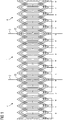
- FIG 1 shows a winding scheme for a segment 1 of a stator of conventional design, which is not part of the claimed invention.
- the winding scheme shown is implemented in a very large dynamoelectric machine, the stator of which is segmented in order to reduce its transport volume to such an extent that the stator can be transported over the road to a later place of use and installed there.
- a typical example of such a dynamo-electric machine is a wind power generator which is designed as a hollow shaft generator.
- An Indian FIG 1 Segment 1 shown in the center is connected to two further segments 4 during the assembly of the wind power generator.
- the further segments 4 adjoin segment 1 at a first and second segment boundary 2, 3.
- the segment 1 and the other segments 4 are largely identical in construction.
- Each of the segments is designed with coils that enable the generation of a rotating field. However, not all coils within segment 1 are closed.
- At the first segment boundary 2 and at the second segment boundary 3 there is a half-coil in each case, which must be electrically connected to a half-coil of one of the further segments 4.
- special connecting coils 15 are used, which over the said half-coils electrically connect the segment boundaries 2, 3. These must still have a certain flexibility in the spool nose.
- the connection coils 15 cannot be insulated as part of the impregnation process of the winding, but must be insulated by hand afterwards.
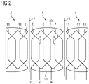
- FIG 2 shows a winding scheme for a segment 1 according to a first embodiment of the invention.
- the winding diagram or segment 1 is intended for a hollow shaft generator of a wind power plant.
- the segment 1 shown in the center is mechanically connected to further segments 4 at a first segment boundary 2 and a second segment boundary 3 during the construction of the wind power generator.
- N segments are provided for the hollow shaft generator, each of the segments 1 spans an arc of a circle with an angle of 360 ° / N with respect to its cross-sectional area.
- Each of the segments 1 comprises three coils 5,6,7 - one coil 5,6,7 for each phase of a three-phase system.
- a pole pair can thus be implemented with each segment 1 for the dynamo-electric machine.
- Two of these coils 5, 6, 7 are closed within segment 1 in a conventional manner.
- a third coil 5 is formed in that a first conductor 8, which is arranged in the vicinity of the first segment boundary 2, is connected via an end connection 10 to a second conductor 9, which is arranged in the vicinity of the second segment boundary 3.
- the coil 5 thus formed encloses the two conventionally closed coils 6, 7.
- the magnetic behavior of such a segment 1 essentially corresponds to a magnetic behavior as it is in a conventional winding according to FIG FIG 1 is achieved.
- FIG 3 shows a winding scheme for a segment 1 according to a second embodiment of the invention.
- three slots per pole and strand are provided here.
- the winding of these coils is analogous to that in FIG 2 shown winding executed. That is, here too, conductors 8, 9 arranged at segment boundaries 2, 3 are connected to one another via end connections 10.
- FIG 2 called.
- FIG 4 shows a wind turbine with a dynamo-electric machine which has a segmented stator.
- the electrical machine 14 is designed as a hollow shaft generator. A gear was dispensed with here, so that the stator of the dynamo-electric machine 14 has a very large diameter.
- the stator has a segmented structure so that it can be assembled at the later place of use by joining the individual segments together. Due to the advantageous configuration of these segments, which are an embodiment according to the present invention, the assembly of the hollow shaft generator is comparatively simple. An electrical connection between the individual segments is not necessary to energize the coils of the segments. This considerably simplifies assembly, since electrical segment connections are made afterwards be pulled between the coils of the segments on the construction site, would still have to be isolated in a complex manner. In contrast, the generator shown here consists of individual, fully electrically functional segments in which this connection is not required.
Landscapes
- Engineering & Computer Science (AREA)
- Power Engineering (AREA)
- Windings For Motors And Generators (AREA)
Description
- Die Erfindung betrifft ein Segment für einen ringförmigen Stator einer dynamoelektrischen Maschine. Die Erfindung kommt insbesondere bei sehr großen elektrischen Maschinen zum Einsatz. Als Beispiel für derartige Maschinen seien Generatoren für Windkraftanlagen, Gezeitenkraftwerke, Ringmotoren oder Antriebe von Baumaschinen wie Bagger genannt.
- Die Energiegewinnung aus regenerativen Energiequellen gewinnt mehr und mehr an Bedeutung. Entsprechend werden auch immer höhere Anforderungen an die zur Energiewandlung eingesetzten Komponenten gestellt. Dies hat beispielsweise zur Folge, dass Generatoren für Windkraftanlagen ein immer größeres Bauvolumen erfordern.
- Mit zunehmender Leistungsklasse werden getriebelose Windenergieanlagen wettbewerbsfähig im Vergleich zu Anlagen, bei denen ein mechanisches Getriebe zwischen den vom Wind angetriebenen Rotorblättern und einem Synchrongenerator geschaltet ist. Hauptvorteil einer solchen getriebelosen Konstruktion ist der im Vergleich zu Windkraftanlagen mit Getriebe deutlich einfachere Aufbau. Durch die Einsparung des Getriebes werden weniger rotierende Maschinenkomponenten benötigt. Hieraus resultieren ein verminderter Wartungsaufwand und eine erhöhte Verfügbarkeit der Anlage.
- Insbesondere sehr große Windkraftanlagen arbeiten in der Regel mit vergleichsweise niedrigen Drehzahlen. Bei einer getriebelosen Ausführung müssen derartige Anlagen daher mit sehr großen und schweren Generatoren ausgestattet werden. Der Durchmesser dieser Maschinen überschreitet hierbei leicht 4 oder 5 m.
- Durch die zunehmende Größe der Windkraftgeneratoren, die die höheren Leistungen dieser Anlagen zwangsläufig mit sich bringen, wird deren Montage immer schwieriger. Getriebelose Turbinen von Windkraft- oder auch Gezeitenkraftwerken stellen jedoch auch große Herausforderungen hinsichtlich Transport und Logistik.
- Generatoren für getriebelose Windkraftanlagen sind häufig mit einem ringförmigen Läufer mit einer Hohlwelle ausgeführt. Eine derartige elektrische Maschine ist beispielsweise aus der
WO 2006/032969 A2 bekannt. Diese Schrift offenbart einen Stator, der in Umfangvorrichtung in mehrere Segmente unterteilt ist. Jedes Statorsegment umfasst ein schwalbenschwanzförmiges Profil, das in ein Fenster eines Statorringes eingreift. So wird jeder dieser Sektoren in axialer Richtung ausziehbar, ohne dass der gesamte Stator abgenommen werden muss. -
EP 1 093 207 A2 ,DE 10 2005 029895 A1 undEP 1 780 869 A2 offenbaren Segmente für einen ringförmigen Stator einer dynamoelektrischen Maschine.EP 2 166 645 A1 offenbart eine verlängerte Stirnverbindung. - Aus der
EP 2 166 645 A1 ist ein Segment gemäß dem Oberbegriff des Anspruchs 1 bekannt. - Der Erfindung liegt die Aufgabe zugrunde, Transport und Montage großer elektrischer Maschinen zu vereinfachen.
- Diese Aufgabe wird durch ein Segment für einen ringförmigen Stator einer dynamoelektrischen Maschine mit den Merkmalen nach Anspruch 1 gelöst.
- Vorteilhafte Ausführungsformen der Erfindung sind den Unteransprüchen zu entnehmen. Der Kerngedanke der Erfindung ist darin zu sehen, dass die Segmente des Stators derart gestaltet sind, dass eine elektrische Verbindung der Segmente untereinander nicht erforderlich ist. Eine solche Verbindung wäre sehr aufwändig. Um sie zu realisieren müssten spezielle Spulen gefertigt werden, die in der Spulennase noch eine gewisse Flexibilität aufweisen und nachträglich in die Nuten des Stators eingelegt werden müssten, um die Segmentgrenzen elektrisch zu überbrücken.
- Diese Spulen müssten dann nach dem eigentlichen Imprägnierprozess der Wicklung noch nachträglich von Hand isoliert werden.
- Eine alternative Lösung zur elektrischen Verbindung der Segmente des Stators wäre darin zu sehen, die Spulen, die an den Segmentgrenzen angeordnet sind, jeweils nur als Halbspulen auszuführen und diese nach dem Aufbau des Stators zusammen zu löten. Jedoch ist auch hier eine nachträgliche Isolierung notwendig. Den oben genannten nachteiligen Verfahren ist gemein, dass eine anschließende zerstörungsfreie Trennung der Segmente beispielsweise zur Wartung oder Reparaturzwecken nicht mehr möglich ist.
- Der Erfindung liegt die Erkenntnis zu Grunde, dass sich die oben beschriebenen problematischen elektrischen Verbindungen zwischen den einzelnen Segmenten des Stators eliminieren lassen, wenn sämtliche Spulen eines Segmentes innerhalb des Segments geschlossen werden. Das bedeutet, dass auch die an den Segmentgrenzen angeordneten Spulen innerhalb des Segmentes geschlossen werden. Dies wird dadurch ermöglicht, dass er an der ersten Segmentgrenze angeordnete erste Leiter über eine verlängerte Stirnverbindung am Wickelkopf mit dem an der zweiten Segmentgrenze angeordneten zweiten Leiter verbunden wird. Somit muss der erste Leiter nicht über die linke Segmentgrenze hinweg mit einem weiteren Leiter eines benachbarten weiteren Segmentes verbunden werden. Als Rückenleiter für den ersten Leiter dient vielmehr der zweite Leiter, der sich an der rechten Segmentgrenze befindet.
- Die durch die Verbindung des ersten und zweiten Leiters geschaffene Spule umschließt die mindestens zwei verbliebenen Spulen. Insgesamt umfasst das erfindungsgemäße Segment daher mindestens drei Spulen. Das Segment kann als vollständige, abgeschlossene Einheit imprägniert werden. Nachträgliche Spulenverbindungen über die Segmentgrenzen hinweg entfallen. Die so entstehenden erfindungsgemäßen Segmente können als abgeschlossene Funktionselemente montiert und beispielsweise zur Wartungs- oder Reparaturzwecken demontiert werden. Hierbei kann anstelle eines kompletten Ständers ein einzelnes Segment als Ersatzteil vorgehalten werden.
- Bei der erfindungsgemäßen elektrischen Maschine kann es sich sowohl um einen Generator als auch um einen Motor handeln. Vorteilhaft ist die erfindungsgemäße Segmentierung des Ständers insbesondere bei sehr großen Bohrungsdurchmessern, unabhängig davon, ob die Maschine in erster Linie für den motorischen oder generatorischen Einsatz vorgesehen ist.
- In vorteilhafter Ausgestaltung der Erfindung sind die Spulen unabhängig von weiteren Spulen der weiteren Segmente zur Erzeugung eines ersten Polpaares eines Drehfeldes mit einem Drehstrom bestrombar.
- Selbstverständlich kann das Segment auch noch mehr Spulen aufweisen, so dass mit deren Hilfe auch eine höhere Polpaarzahl als eins erzeugt werden kann. So ist eine Ausgestaltungsform der Erfindung vorteilhaft, bei der das Segment für jede Phase des Drehstromsystems mindestens eine innerhalb des Segmentes geschlossene zweite Spule zur Erzeugung eines zweiten Polpaares aufweist, die unabhängig von weiteren Spulen der weiteren Segmente zur Erzeugung eines zweiten Polpaares des Drehfeldes mit dem Drehstrom bestrombar sind.
- Die zweckmäßigerweise als Umfangswicklung ausgeführten Wicklungen sind in vorteilhafter Ausgestaltung der Erfindung derart gestaltet, dass die Spulen als Etagenwicklung angeordnet sind, so dass sich die Leiter der drei Spulen eines Polpaares im Bereich der Wickelköpfe überlagern.
- Eine einfache Herstellung eines solchen Segmentes ist hierbei in weiterer vorteilhafter Ausgestaltung der Erfindung dadurch gegeben, dass die Spulen als Einschichtwicklung ausgebildet sind.
- Selbstverständlich ist alternativ jedoch eine Ausgestaltung der Erfindung denkbar, bei der die Spulen als Zweischichtwicklung ausgebildet sind.
- Insbesondere bei sehr großen elektrodynamischen Maschinen wird ein erheblicher Transportvorteil dadurch erzielt, dass die geschlossene Ringform des Stators durch Trennen der Segmente voneinander aufhebbar ist. Bei einer derartigen Ausgestaltung muss beispielsweise über die Straße nicht mehr der komplette Hohlzylinder transportiert werden, der den vollständigen Stator bildet. Die einzelnen Segmente nehmen im demontierten Zustand deutlich weniger Volumen in Anspruch als im montierten Zustand.
- Vorteilhaft ist ebenso eine Ausgestaltung der Erfindung, bei der eine dynamoelektrische Maschine mit mindestens zwei Segmenten einer der zuvor beschriebenen Ausführungsformen als direkt angetriebener Generator für eine Windkraftanlage oder ein Gezeitenkraftwerk ausgebildet ist. Derartige Generatoren benötigen ein hohes Bauvolumen, um aufgrund der niedrigen Drehzahlen, die sich mit den hier genutzten Antriebskräften erzeugen lassen, eine hohe elektrische Leistung zu liefern. Ebenfalls vorteilhaft ist der Einsatz einer elektrodynamischen Maschine mit segmentiertem Ständer entsprechend einer Ausführungsform der Erfindung in zahlreichen anderen Einsatzbereichen, die ein großes Drehmoment und damit einen großen Maschinendurchmesser erforderlich machen.
- Eine Windkraftanlage mit einer dynamoelektrischen Maschine, deren Ständer aus einzelnen teilringförmigen Segmenten einer der zuvor beschriebenen Ausführungsformen gefertigt ist, lässt sich sehr leicht an ihrem späteren Einsatzort montieren. Die einzelnen Segmente des Stators können im Vergleich zu einer kompletten dynamoelektrischen Maschine sehr viel besser zum Aufbauort z.B. über die Straße transportiert werden.
- Im Folgenden wird die Erfindung anhand der in den Figuren dargestellten Ausführungsbeispiele näher beschrieben und erläutert. Es zeigen:
- FIG 1
- ein Wicklungsschema für ein Segment eines Stators in konventioneller Ausführung,
- FIG 2
- ein Wicklungsschema für ein Segment gemäß einer ersten Ausgestaltung der Erfindung,
- FIG 3
- ein Wicklungsschema für ein Segment gemäß einer zweiten Ausgestaltung der Erfindung und
- FIG 4
- eine Windkraftanlage mit einer dynamoelektrischen Maschine, die einen segmentierten Stator aufweist.
-
FIG 1 zeigt ein Wicklungsschema für ein Segment 1 eines Stators in konventioneller Ausführung, das nicht Teil der beanspruchten Erfindung ist. Das dargestellte Wicklungsschema ist bei einer sehr großen dynamoelektrischen Maschine realisiert, deren Stator segmentiert ausgeführt ist, um dessen Transportvolumen soweit zu reduzieren, dass der Stator über die Straße zu einem späteren Einsatzort transportiert und dort montiert werden kann. Ein typisches Beispiel für eine derartige dynamoelektrische Maschine ist ein Windkraftgenerator, der als Hohlwellengenerator ausgeführt ist. - Ein in der
FIG 1 mittig dargestelltes Segment 1 wird bei der Montage des Windkraftgenerators mit zwei weiteren Segmenten 4 verbunden. Die weiteren Segmente 4 schließen sich dem Segment 1 an einer ersten und zweiten Segmentgrenze 2,3 an. Das Segment 1 und die weiteren Segmente 4 sind weitgehend baugleich ausgeführt. Jedes der Segmente ist mit Spulen ausgeführt, die die Erzeugung eines Drehfeldes ermöglichen. Jedoch sind nicht alle Spulen innerhalb des Segmentes 1 geschlossen. An der ersten Segmentgrenze 2 und an der zweiten Segmentgrenze 3 befindet sich jeweils eine Halbspule, die mit einer Halbspule eines der weiteren Segmente 4 elektrisch verbunden werden muss. Um dies zu ermöglichen, werden nach dem Aneinanderfügen des Segmentes 1 mit den weiteren Segmenten 4 spezielle Verbindungsspulen 15 verwendet, die die besagten Halbspulen über die Segmentgrenzen 2,3 hinweg elektrisch verbinden. Diese müssen in der Spulennase noch eine gewisse Flexibilität aufweisen. Die Verbindungsspulen 15 können dadurch nicht im Zuge des Imprägnierprozesses der Wicklung mitisoliert werden sondern müssen nachträglich von Hand isoliert werden. -
FIG 2 zeigt ein Wicklungsschema für ein Segment 1 gemäß einer ersten Ausgestaltung der Erfindung. Auch hier sei angenommen, dass das Wicklungsschema bzw. das Segment 1 für einen Hohlwellengenerator einer Windkraftanlage vorgesehen ist. Das mittig dargestellte Segment 1 wird beim Aufbau des Windkraftgenerators an einer ersten Segmentgrenze 2 und einer zweiten Segmentgrenze 3 mit weiteren Segmenten 4 mechanisch verbunden. Sind N-Segmente für den Hohlwellengenerator vorgesehen, so spannt jedes der Segmente 1 bezüglich seiner Querschnittsfläche einen Kreisbogen mit einem Winkel von 360°/N auf. - Jedes der Segmente 1 umfasst drei Spulen 5,6,7 - jeweils eine Spule 5,6,7 für jede Phase eines Drehstromsystems. Somit lässt sich ein Polpaar mit jedem Segment 1 für die dynamoelektrische Maschine realisieren. Zwei dieser Spulen 5,6,7 sind auf herkömmliche Weise innerhalb des Segmentes 1 geschlossen. Eine dritte Spule 5 wird dadurch gebildet, dass ein erster Leiter 8, der in der Nähe der ersten Segmentgrenze 2 angeordnet ist, über eine Stirnverbindung 10 mit einem zweiten Leiter 9 verbunden wird, der in der Nähe der zweiten Segmentgrenze 3 angeordnet ist. Auf diese Art und Weise umschließt die so gebildete Spule 5 die zwei herkömmlich geschlossenen Spulen 6,7. Das magnetische Verhalten eines derartigen Segmentes 1 entspricht im Wesentlichen einem magnetischen Verhalten, wie es bei einer konventionellen Wicklung gemäß
FIG 1 erzielt wird. Jedoch sind keine Verbindungselemente notwendig, die die Spulen 5,6,7 mit weiteren Spulen 11 der weiteren Segmente 4 elektrisch verbinden. Die Montage eines derartigen Hohlwellengenerators gestaltet sich deutlich einfacher, da jedes Segment 1 für sich autark bestromt werden kann und keine elektrische Verbindung und die damit verbundene nachträgliche Isolierung über die Segmentgrenzen 2,3 hinweg erforderlich ist. Auch Wartungs- und Reparaturarbeiten werden durch diese Ausgestaltung des Hohlwellengenerators deutlich vereinfacht. Tritt ein Defekt an einem Segment 1 auf, so kann dieses ausgetauscht werden, ohne das hierfür irgendwie geartete, Segmentgrenzen 2,3 überwindende Verbindungselemente aufgetrennt werden müssen. Einzelne Segmente 1 können als Ersatzteile vorgehalten werden, so dass ein Austausch im Falle eines Defektes zeitnah erfolgen kann. Stillstandszeiten werden auf diese Art und Weise erheblich reduziert. -
FIG 3 zeigt ein Wicklungsschema für ein Segment 1 gemäß einer zweiten Ausgestaltung der Erfindung. Im Gegensatz zu der ersten Ausgestaltung gemäßFIG 2 sind hier drei Nuten pro Pol und Strang vorgesehen. Daraus ergibt sich, dass für jede Phase eine Spulengruppe bestehend aus drei konzentrisch zueinander angeordneten Spulen vorgesehen ist. Die Wicklung dieser Spulen ist analog zu der inFIG 2 dargestellten Wicklung ausgeführt. D.h., auch hier werden an den Segmentgrenzen 2,3 angeordnete Leiter 8,9 über Stirnverbindungen 10 miteinander verbunden. Die sich daraus ergebenden Vorteile sind bereits in der Beschreibung zuFIG 2 genannt. -
FIG 4 zeigt eine Windkraftanlage mit einer dynamoelektrischen Maschine, die einen segmentierten Stator aufweist. Die elektrische Maschine 14 ist als Hohlwellengenerator ausgeführt. Auf ein Getriebe wurde hierbei verzichtet, so dass der Stator der dynamoelektrischen Maschine 14 einen sehr großen Durchmesser aufweist. Der Stator ist segmentiert aufgebaut, so dass er durch Aneinanderfügen der einzelnen Segmente am späteren Einsatzort montiert werden kann. Aufgrund der vorteilhaften Ausgestaltung dieser Segmente, bei denen es sich um eine Ausführung gemäß der vorliegenden Erfindung handelt, gestaltet sich die Montage des Hohlwellengenerators vergleichsweise einfach. Eine elektrische Verbindung der einzelnen Segmente untereinander ist zur Bestromung der Spulen der Segmente nicht notwendig. Hierdurch wird die Montage erheblich vereinfacht, da elektrische Segmentverbindungen, die im Nachhinein auf der Baustelle zwischen den Spulen der Segmente gezogen werden, noch aufwändig isoliert werden müssten. Hingegen besteht der hier dargestellte Generator aus einzelnen voll elektrisch funktionstüchtigen Segmenten, bei denen diese Verbindung nicht benötigt wird.
Claims (8)
- Segment (1) für einen ringförmigen Stator einer dynamoelektrischen Maschine (14), das einen im Wesentlichen kreisbogenförmigen Querschnitt umfasst, wobei das Segment (1) aufweist:- eine erste und eine zweite Segmentgrenze (2,3), an die ein weiteres Segment (4) angefügt werden kann,- mindestens eine Spule (5,6,7) für jede Phase eines Drehstromsystems,- mindestens einen ersten Leiter (8) und mindestens einen zweiten Leiter (9) aufweist,
wobei- der erste Leiter (8) an der ersten Segmentgrenze (2) mit dem zweiten Leiter (9) an der zweiten Segmentgrenze (3) über eine verlängerte Stirnverbindung (10) im Bereich der Wickelköpfe verbunden ist, so dass die so gebildete Spule (5) zumindest die zwei verbleibenden Spulen (6,7) umschließt,
wobei die Spulen (5,6,7) unabhängig von weiteren Spulen (11) der weiteren Segmente (4) zur Erzeugung eines ersten Polpaares eines Drehfeldes mit einem Drehstrom bestrombar sind, dadurch gekennzeichnet, dass das Segment (1) für jede Phase des Drehstromsystems mindestens eine innerhalb des Segmentes (1) geschlossene zweite Spule zur Erzeugung eines zweiten Polpaares aufweist, die unabhängig von den weiteren Spulen (11) der weiteren Segmente (4) zur Erzeugung eines zweiten Polpaares des Drehfeldes mit dem Drehstrom bestrombar sind. - Segment nach Anspruch 1,
wobei die Spulen (5,6,7) als Etagenwicklung angeordnet sind, so dass sich die Leiter der drei Spulen (5,6,7) eines Polpaares im Bereich der Wickelköpfe überlagern. - Segment nach einem der vorhergehenden Ansprüche,
wobei die Spulen (5,6,7) als Einschichtwicklung ausgebildet sind. - Segment nach einem der vorhergehenden Ansprüche,
wobei die Spulen (5,6,7) als Zweischichtwicklung ausgebildet sind. - Segment nach einem der Ansprüche 1 bis 4,
die geschlossene Ringform des Stators durch Trennen der Segmente (1,4) voneinander aufhebbar ist. - Dynamoelektrische Maschine (14) mit mindestens zwei Segmenten (1,4) nach einem der Ansprüche 1 bis 5.
- Dynamoelektrische Maschine (14) nach Anspruch 6, wobei die dynamoelektrische Maschine (14) als direkt angetriebener Generator für eine Windkraftanlage oder ein Gezeitenkraftwerk ausgebildet ist.
- Windkraftanlage mit einer dynamoelektrischen Maschine (14) nach einem der Ansprüche 6 oder 7.
Applications Claiming Priority (1)
| Application Number | Priority Date | Filing Date | Title |
|---|---|---|---|
| DE102009032880A DE102009032880A1 (de) | 2009-07-13 | 2009-07-13 | Wicklungsschema für einen segmentierten Ständer einer dynamoelektrischen Maschine |
Publications (3)
| Publication Number | Publication Date |
|---|---|
| EP2276149A2 EP2276149A2 (de) | 2011-01-19 |
| EP2276149A3 EP2276149A3 (de) | 2016-11-09 |
| EP2276149B1 true EP2276149B1 (de) | 2021-04-21 |
Family
ID=42983613
Family Applications (1)
| Application Number | Title | Priority Date | Filing Date |
|---|---|---|---|
| EP10164078.7A Active EP2276149B1 (de) | 2009-07-13 | 2010-05-27 | Wicklungsschema für einen segmentierten Ständer einer dynamoelektrischen Maschine |
Country Status (5)
| Country | Link |
|---|---|
| US (1) | US8497614B2 (de) |
| EP (1) | EP2276149B1 (de) |
| DE (1) | DE102009032880A1 (de) |
| DK (1) | DK2276149T3 (de) |
| ES (1) | ES2875419T3 (de) |
Families Citing this family (6)
| Publication number | Priority date | Publication date | Assignee | Title |
|---|---|---|---|---|
| DE102009031371B4 (de) | 2009-07-01 | 2011-05-26 | Siemens Aktiengesellschaft | Läufer und Verfahren zur Herstellung eines Läufers einer elektrischen Maschine |
| ES2696544T3 (es) * | 2010-11-05 | 2019-01-16 | Vestas Wind Sys As | Generador segmentado de accionamiento directo |
| ES2428017T3 (es) | 2011-04-04 | 2013-11-05 | Siemens Aktiengesellschaft | Procedimiento para montar una máquina eléctrica |
| DE102012210614A1 (de) | 2012-06-22 | 2013-12-24 | Siemens Aktiengesellschaft | Verringerung des elektrischen Widerstandes bei einer elektrischen Maschine mit in Nuten angeordneten Wicklungen |
| US20170033631A1 (en) * | 2015-07-29 | 2017-02-02 | Siemens Energy, Inc. | Method for roebel transposition of form wound conductors of electrical machines such as generators and motors |
| EP4478587A1 (de) * | 2023-06-16 | 2024-12-18 | Siemens Gamesa Renewable Energy A/S | Stator einer elektrischen maschine |
Family Cites Families (15)
| Publication number | Priority date | Publication date | Assignee | Title |
|---|---|---|---|---|
| US1799021A (en) * | 1926-04-16 | 1931-03-31 | Parsons | Electrical conductor |
| FR2208234B1 (de) * | 1972-11-27 | 1975-03-28 | Merlin Gerin | |
| US4103213A (en) * | 1976-09-16 | 1978-07-25 | Emerson Electric Co. | Two speed single phase induction motor |
| JP3484006B2 (ja) * | 1996-01-30 | 2004-01-06 | 株式会社日立製作所 | 回転機および成形方法 |
| US5811905A (en) * | 1997-01-07 | 1998-09-22 | Emerson Electric Co. | Doubly-fed switched reluctance machine |
| AT6706U1 (de) * | 1999-10-11 | 2004-02-25 | Innova Patent Gmbh | Elektromotor |
| JP2004282858A (ja) * | 2003-03-14 | 2004-10-07 | Hitachi Ltd | 固定子及びそれを用いた回転機 |
| ITBZ20040047A1 (it) | 2004-09-20 | 2004-12-20 | High Technology Invest Bv | Generatore/motore elettrico, in particolare per l'impiego in impianti eolici, impianti a fune o idraulici. |
| DE102005029895A1 (de) * | 2005-06-27 | 2007-01-04 | Siemens Ag | Direktantrieb für Großantriebe |
| US7348706B2 (en) * | 2005-10-31 | 2008-03-25 | A. O. Smith Corporation | Stator assembly for an electric machine and method of manufacturing the same |
| DE102006021354A1 (de) | 2006-05-08 | 2007-11-15 | Siemens Ag | Elektrische Maschine, insbesondere Synchronmotor, mit redundanten Statorwicklungen |
| US8222792B2 (en) * | 2006-08-04 | 2012-07-17 | Clean Current Limited Partnership | Axial air gap machine having stator and rotor discs formed of multiple detachable segments |
| US20090021093A1 (en) * | 2007-07-17 | 2009-01-22 | Taco, Inc. | Electric Motors |
| DE102007042338A1 (de) * | 2007-09-06 | 2009-03-12 | Siemens Ag | Windkraftanlage mit Wärmetauschersystem |
| ES2399454T3 (es) * | 2008-09-18 | 2013-04-01 | Siemens Aktiengesellschaft | Grupo de tres devanados de estator para un estator de una máquina eléctrica, disposición de estator, generador y turbina eólica |
-
2009
- 2009-07-13 DE DE102009032880A patent/DE102009032880A1/de not_active Withdrawn
-
2010
- 2010-05-27 ES ES10164078T patent/ES2875419T3/es active Active
- 2010-05-27 EP EP10164078.7A patent/EP2276149B1/de active Active
- 2010-05-27 DK DK10164078.7T patent/DK2276149T3/da active
- 2010-07-12 US US12/834,421 patent/US8497614B2/en active Active
Non-Patent Citations (1)
| Title |
|---|
| None * |
Also Published As
| Publication number | Publication date |
|---|---|
| EP2276149A3 (de) | 2016-11-09 |
| DE102009032880A1 (de) | 2011-01-20 |
| EP2276149A2 (de) | 2011-01-19 |
| ES2875419T3 (es) | 2021-11-10 |
| US20110163550A1 (en) | 2011-07-07 |
| DK2276149T3 (da) | 2021-06-28 |
| US8497614B2 (en) | 2013-07-30 |
Similar Documents
| Publication | Publication Date | Title |
|---|---|---|
| EP2508749B1 (de) | Verfahren zum Montieren einer elektrischen Maschine | |
| EP1574708B1 (de) | Windenergieanlage mit Ringgenerator | |
| EP3038233B1 (de) | Permanentmagnet-synchronmotor und elektrische servolenkung | |
| WO2011006810A2 (de) | Ringförmiger rotor für eine elektrische maschine | |
| EP3180838A1 (de) | Verfahren zum herstellen einer formspule für ein statorblechpaket | |
| DE102019103191A1 (de) | Stator für eine elektrische Maschine | |
| DE102007054719A1 (de) | Elektrische Drehfeldmaschine | |
| EP3455921B1 (de) | Synchrongenerator einer getriebelosen windenergieanlage sowie verfahren zum herstellen eines synchrongenerators | |
| EP2276149A2 (de) | Wicklungsschema für einen segmentierten Ständer einer dynamoelektrischen Maschine | |
| WO2019215097A1 (de) | Verfahren zum herstellen einer wicklung für einen ständer einer elektrischen machine und elektrische maschine | |
| WO2011006809A2 (de) | Segmentierter ständer für eine dynamoelektrische maschine | |
| DE102012214523B4 (de) | Ständer oder Ständersegment einer dynamoelektrischen Maschine mit optimiertem Wickelkopf, dynamoelektrische Maschine und Rohrmühle oder Windkraftgenerator | |
| WO2016023934A1 (de) | Verfahren zum herstellen eines bürstenkommutierten gleichstrommotors | |
| EP3100338B1 (de) | Zusammengesetzte elektrische maschine | |
| EP3048702A1 (de) | Rotor einer Reluktanzmaschine | |
| EP2436106B1 (de) | Verfahren zur herstellung einer ständerwicklung einer elektrischen maschine, insbesondere eines wechselstromgenerators | |
| WO2019149508A1 (de) | Rotor mit kühlkanälen | |
| DE102020203945A1 (de) | Statorwicklungssystem mit serieller Spulenwicklung | |
| EP4133573B1 (de) | Haltesystem für stromschienen an statoren bzw. statorsegmenten dynamoelektrischer maschinen | |
| WO2014184180A2 (de) | Bürstenkommutierter gleichstrommotor | |
| EP3007328A1 (de) | Aktivteil einer elektrischen Maschine | |
| DE102009001543A1 (de) | Elektrische Maschine und Verfahren zur Herstellung einer elektrischen Maschine | |
| DE102010028869A1 (de) | Dynamoelektrische Maschine mit einer Einschichtwicklung für Großantriebe | |
| DE102011084714A1 (de) | Elektrische Maschine | |
| EP3180841A1 (de) | Bürstenkommutierter gleichstrommotor |
Legal Events
| Date | Code | Title | Description |
|---|---|---|---|
| PUAI | Public reference made under article 153(3) epc to a published international application that has entered the european phase |
Free format text: ORIGINAL CODE: 0009012 |
|
| AK | Designated contracting states |
Kind code of ref document: A2 Designated state(s): AL AT BE BG CH CY CZ DE DK EE ES FI FR GB GR HR HU IE IS IT LI LT LU LV MC MK MT NL NO PL PT RO SE SI SK SM TR |
|
| AX | Request for extension of the european patent |
Extension state: BA ME RS |
|
| RAP1 | Party data changed (applicant data changed or rights of an application transferred) |
Owner name: SIEMENS AKTIENGESELLSCHAFT |
|
| PUAL | Search report despatched |
Free format text: ORIGINAL CODE: 0009013 |
|
| AK | Designated contracting states |
Kind code of ref document: A3 Designated state(s): AL AT BE BG CH CY CZ DE DK EE ES FI FR GB GR HR HU IE IS IT LI LT LU LV MC MK MT NL NO PL PT RO SE SI SK SM TR |
|
| AX | Request for extension of the european patent |
Extension state: BA ME RS |
|
| RIC1 | Information provided on ipc code assigned before grant |
Ipc: H02K 3/12 20060101AFI20160930BHEP |
|
| STAA | Information on the status of an ep patent application or granted ep patent |
Free format text: STATUS: REQUEST FOR EXAMINATION WAS MADE |
|
| 17P | Request for examination filed |
Effective date: 20170505 |
|
| RBV | Designated contracting states (corrected) |
Designated state(s): AL AT BE BG CH CY CZ DE DK EE ES FI FR GB GR HR HU IE IS IT LI LT LU LV MC MK MT NL NO PL PT RO SE SI SK SM TR |
|
| RAP1 | Party data changed (applicant data changed or rights of an application transferred) |
Owner name: SIEMENS AKTIENGESELLSCHAFT |
|
| STAA | Information on the status of an ep patent application or granted ep patent |
Free format text: STATUS: EXAMINATION IS IN PROGRESS |
|
| 17Q | First examination report despatched |
Effective date: 20200225 |
|
| REG | Reference to a national code |
Ref country code: DE Ref legal event code: R079 Ref document number: 502010016896 Country of ref document: DE Free format text: PREVIOUS MAIN CLASS: H02K0003120000 Ipc: H02K0003280000 |
|
| GRAP | Despatch of communication of intention to grant a patent |
Free format text: ORIGINAL CODE: EPIDOSNIGR1 |
|
| STAA | Information on the status of an ep patent application or granted ep patent |
Free format text: STATUS: GRANT OF PATENT IS INTENDED |
|
| RAP1 | Party data changed (applicant data changed or rights of an application transferred) |
Owner name: FLENDER GMBH |
|
| INTG | Intention to grant announced |
Effective date: 20201211 |
|
| RIC1 | Information provided on ipc code assigned before grant |
Ipc: H02K 7/18 20060101ALI20201130BHEP Ipc: H02K 3/28 20060101AFI20201130BHEP Ipc: H02K 1/14 20060101ALI20201130BHEP |
|
| GRAS | Grant fee paid |
Free format text: ORIGINAL CODE: EPIDOSNIGR3 |
|
| GRAA | (expected) grant |
Free format text: ORIGINAL CODE: 0009210 |
|
| STAA | Information on the status of an ep patent application or granted ep patent |
Free format text: STATUS: THE PATENT HAS BEEN GRANTED |
|
| AK | Designated contracting states |
Kind code of ref document: B1 Designated state(s): AL AT BE BG CH CY CZ DE DK EE ES FI FR GB GR HR HU IE IS IT LI LT LU LV MC MK MT NL NO PL PT RO SE SI SK SM TR |
|
| REG | Reference to a national code |
Ref country code: GB Ref legal event code: FG4D Free format text: NOT ENGLISH |
|
| REG | Reference to a national code |
Ref country code: CH Ref legal event code: EP |
|
| REG | Reference to a national code |
Ref country code: DE Ref legal event code: R096 Ref document number: 502010016896 Country of ref document: DE |
|
| REG | Reference to a national code |
Ref country code: IE Ref legal event code: FG4D Free format text: LANGUAGE OF EP DOCUMENT: GERMAN |
|
| REG | Reference to a national code |
Ref country code: AT Ref legal event code: REF Ref document number: 1385676 Country of ref document: AT Kind code of ref document: T Effective date: 20210515 |
|
| REG | Reference to a national code |
Ref country code: DK Ref legal event code: T3 Effective date: 20210621 |
|
| REG | Reference to a national code |
Ref country code: NL Ref legal event code: FP |
|
| REG | Reference to a national code |
Ref country code: FI Ref legal event code: FGE |
|
| REG | Reference to a national code |
Ref country code: SE Ref legal event code: TRGR |
|
| PGFP | Annual fee paid to national office [announced via postgrant information from national office to epo] |
Ref country code: NL Payment date: 20210617 Year of fee payment: 12 Ref country code: DE Payment date: 20210527 Year of fee payment: 12 Ref country code: FR Payment date: 20210617 Year of fee payment: 12 Ref country code: FI Payment date: 20210616 Year of fee payment: 12 |
|
| REG | Reference to a national code |
Ref country code: LT Ref legal event code: MG9D |
|
| PGFP | Annual fee paid to national office [announced via postgrant information from national office to epo] |
Ref country code: GB Payment date: 20210525 Year of fee payment: 12 Ref country code: DK Payment date: 20210623 Year of fee payment: 12 Ref country code: AT Payment date: 20210621 Year of fee payment: 12 Ref country code: SE Payment date: 20210618 Year of fee payment: 12 |
|
| REG | Reference to a national code |
Ref country code: EE Ref legal event code: FG4A Ref document number: E021178 Country of ref document: EE Effective date: 20210721 |
|
| PG25 | Lapsed in a contracting state [announced via postgrant information from national office to epo] |
Ref country code: LT Free format text: LAPSE BECAUSE OF FAILURE TO SUBMIT A TRANSLATION OF THE DESCRIPTION OR TO PAY THE FEE WITHIN THE PRESCRIBED TIME-LIMIT Effective date: 20210421 Ref country code: BG Free format text: LAPSE BECAUSE OF FAILURE TO SUBMIT A TRANSLATION OF THE DESCRIPTION OR TO PAY THE FEE WITHIN THE PRESCRIBED TIME-LIMIT Effective date: 20210721 Ref country code: HR Free format text: LAPSE BECAUSE OF FAILURE TO SUBMIT A TRANSLATION OF THE DESCRIPTION OR TO PAY THE FEE WITHIN THE PRESCRIBED TIME-LIMIT Effective date: 20210421 |
|
| PGFP | Annual fee paid to national office [announced via postgrant information from national office to epo] |
Ref country code: EE Payment date: 20210617 Year of fee payment: 12 |
|
| REG | Reference to a national code |
Ref country code: ES Ref legal event code: FG2A Ref document number: 2875419 Country of ref document: ES Kind code of ref document: T3 Effective date: 20211110 |
|
| PG25 | Lapsed in a contracting state [announced via postgrant information from national office to epo] |
Ref country code: IS Free format text: LAPSE BECAUSE OF FAILURE TO SUBMIT A TRANSLATION OF THE DESCRIPTION OR TO PAY THE FEE WITHIN THE PRESCRIBED TIME-LIMIT Effective date: 20210821 Ref country code: LV Free format text: LAPSE BECAUSE OF FAILURE TO SUBMIT A TRANSLATION OF THE DESCRIPTION OR TO PAY THE FEE WITHIN THE PRESCRIBED TIME-LIMIT Effective date: 20210421 Ref country code: GR Free format text: LAPSE BECAUSE OF FAILURE TO SUBMIT A TRANSLATION OF THE DESCRIPTION OR TO PAY THE FEE WITHIN THE PRESCRIBED TIME-LIMIT Effective date: 20210722 Ref country code: NO Free format text: LAPSE BECAUSE OF FAILURE TO SUBMIT A TRANSLATION OF THE DESCRIPTION OR TO PAY THE FEE WITHIN THE PRESCRIBED TIME-LIMIT Effective date: 20210721 Ref country code: PT Free format text: LAPSE BECAUSE OF FAILURE TO SUBMIT A TRANSLATION OF THE DESCRIPTION OR TO PAY THE FEE WITHIN THE PRESCRIBED TIME-LIMIT Effective date: 20210823 Ref country code: PL Free format text: LAPSE BECAUSE OF FAILURE TO SUBMIT A TRANSLATION OF THE DESCRIPTION OR TO PAY THE FEE WITHIN THE PRESCRIBED TIME-LIMIT Effective date: 20210421 |
|
| PGFP | Annual fee paid to national office [announced via postgrant information from national office to epo] |
Ref country code: ES Payment date: 20210721 Year of fee payment: 12 |
|
| REG | Reference to a national code |
Ref country code: CH Ref legal event code: PL |
|
| REG | Reference to a national code |
Ref country code: DE Ref legal event code: R097 Ref document number: 502010016896 Country of ref document: DE |
|
| PG25 | Lapsed in a contracting state [announced via postgrant information from national office to epo] |
Ref country code: CZ Free format text: LAPSE BECAUSE OF FAILURE TO SUBMIT A TRANSLATION OF THE DESCRIPTION OR TO PAY THE FEE WITHIN THE PRESCRIBED TIME-LIMIT Effective date: 20210421 Ref country code: SK Free format text: LAPSE BECAUSE OF FAILURE TO SUBMIT A TRANSLATION OF THE DESCRIPTION OR TO PAY THE FEE WITHIN THE PRESCRIBED TIME-LIMIT Effective date: 20210421 Ref country code: SM Free format text: LAPSE BECAUSE OF FAILURE TO SUBMIT A TRANSLATION OF THE DESCRIPTION OR TO PAY THE FEE WITHIN THE PRESCRIBED TIME-LIMIT Effective date: 20210421 Ref country code: MC Free format text: LAPSE BECAUSE OF FAILURE TO SUBMIT A TRANSLATION OF THE DESCRIPTION OR TO PAY THE FEE WITHIN THE PRESCRIBED TIME-LIMIT Effective date: 20210421 Ref country code: LU Free format text: LAPSE BECAUSE OF NON-PAYMENT OF DUE FEES Effective date: 20210527 Ref country code: LI Free format text: LAPSE BECAUSE OF NON-PAYMENT OF DUE FEES Effective date: 20210531 Ref country code: CH Free format text: LAPSE BECAUSE OF NON-PAYMENT OF DUE FEES Effective date: 20210531 Ref country code: RO Free format text: LAPSE BECAUSE OF FAILURE TO SUBMIT A TRANSLATION OF THE DESCRIPTION OR TO PAY THE FEE WITHIN THE PRESCRIBED TIME-LIMIT Effective date: 20210421 |
|
| REG | Reference to a national code |
Ref country code: BE Ref legal event code: MM Effective date: 20210531 |
|
| PLBE | No opposition filed within time limit |
Free format text: ORIGINAL CODE: 0009261 |
|
| STAA | Information on the status of an ep patent application or granted ep patent |
Free format text: STATUS: NO OPPOSITION FILED WITHIN TIME LIMIT |
|
| 26N | No opposition filed |
Effective date: 20220124 |
|
| PG25 | Lapsed in a contracting state [announced via postgrant information from national office to epo] |
Ref country code: IE Free format text: LAPSE BECAUSE OF NON-PAYMENT OF DUE FEES Effective date: 20210527 |
|
| PG25 | Lapsed in a contracting state [announced via postgrant information from national office to epo] |
Ref country code: IS Free format text: LAPSE BECAUSE OF FAILURE TO SUBMIT A TRANSLATION OF THE DESCRIPTION OR TO PAY THE FEE WITHIN THE PRESCRIBED TIME-LIMIT Effective date: 20210821 Ref country code: AL Free format text: LAPSE BECAUSE OF FAILURE TO SUBMIT A TRANSLATION OF THE DESCRIPTION OR TO PAY THE FEE WITHIN THE PRESCRIBED TIME-LIMIT Effective date: 20210421 |
|
| PG25 | Lapsed in a contracting state [announced via postgrant information from national office to epo] |
Ref country code: IT Free format text: LAPSE BECAUSE OF FAILURE TO SUBMIT A TRANSLATION OF THE DESCRIPTION OR TO PAY THE FEE WITHIN THE PRESCRIBED TIME-LIMIT Effective date: 20210421 Ref country code: BE Free format text: LAPSE BECAUSE OF NON-PAYMENT OF DUE FEES Effective date: 20210531 |
|
| REG | Reference to a national code |
Ref country code: DE Ref legal event code: R119 Ref document number: 502010016896 Country of ref document: DE |
|
| REG | Reference to a national code |
Ref country code: EE Ref legal event code: MM4A Ref document number: E021178 Country of ref document: EE Effective date: 20220531 |
|
| REG | Reference to a national code |
Ref country code: DK Ref legal event code: EBP Effective date: 20220531 |
|
| REG | Reference to a national code |
Ref country code: SE Ref legal event code: EUG |
|
| REG | Reference to a national code |
Ref country code: NL Ref legal event code: MM Effective date: 20220601 |
|
| REG | Reference to a national code |
Ref country code: AT Ref legal event code: MM01 Ref document number: 1385676 Country of ref document: AT Kind code of ref document: T Effective date: 20220527 |
|
| GBPC | Gb: european patent ceased through non-payment of renewal fee |
Effective date: 20220527 |
|
| PG25 | Lapsed in a contracting state [announced via postgrant information from national office to epo] |
Ref country code: SE Free format text: LAPSE BECAUSE OF NON-PAYMENT OF DUE FEES Effective date: 20220528 Ref country code: FI Free format text: LAPSE BECAUSE OF NON-PAYMENT OF DUE FEES Effective date: 20220527 Ref country code: EE Free format text: LAPSE BECAUSE OF NON-PAYMENT OF DUE FEES Effective date: 20220531 Ref country code: AT Free format text: LAPSE BECAUSE OF NON-PAYMENT OF DUE FEES Effective date: 20220527 |
|
| PG25 | Lapsed in a contracting state [announced via postgrant information from national office to epo] |
Ref country code: FR Free format text: LAPSE BECAUSE OF NON-PAYMENT OF DUE FEES Effective date: 20220531 Ref country code: DK Free format text: LAPSE BECAUSE OF NON-PAYMENT OF DUE FEES Effective date: 20220531 |
|
| PG25 | Lapsed in a contracting state [announced via postgrant information from national office to epo] |
Ref country code: HU Free format text: LAPSE BECAUSE OF FAILURE TO SUBMIT A TRANSLATION OF THE DESCRIPTION OR TO PAY THE FEE WITHIN THE PRESCRIBED TIME-LIMIT; INVALID AB INITIO Effective date: 20100527 Ref country code: GB Free format text: LAPSE BECAUSE OF NON-PAYMENT OF DUE FEES Effective date: 20220527 Ref country code: DE Free format text: LAPSE BECAUSE OF NON-PAYMENT OF DUE FEES Effective date: 20221201 Ref country code: CY Free format text: LAPSE BECAUSE OF FAILURE TO SUBMIT A TRANSLATION OF THE DESCRIPTION OR TO PAY THE FEE WITHIN THE PRESCRIBED TIME-LIMIT Effective date: 20210421 |
|
| PG25 | Lapsed in a contracting state [announced via postgrant information from national office to epo] |
Ref country code: NL Free format text: LAPSE BECAUSE OF NON-PAYMENT OF DUE FEES Effective date: 20220601 |
|
| REG | Reference to a national code |
Ref country code: ES Ref legal event code: FD2A Effective date: 20230728 |
|
| PG25 | Lapsed in a contracting state [announced via postgrant information from national office to epo] |
Ref country code: ES Free format text: LAPSE BECAUSE OF NON-PAYMENT OF DUE FEES Effective date: 20220528 |
|
| PG25 | Lapsed in a contracting state [announced via postgrant information from national office to epo] |
Ref country code: MK Free format text: LAPSE BECAUSE OF FAILURE TO SUBMIT A TRANSLATION OF THE DESCRIPTION OR TO PAY THE FEE WITHIN THE PRESCRIBED TIME-LIMIT Effective date: 20210421 |
|
| PG25 | Lapsed in a contracting state [announced via postgrant information from national office to epo] |
Ref country code: TR Free format text: LAPSE BECAUSE OF FAILURE TO SUBMIT A TRANSLATION OF THE DESCRIPTION OR TO PAY THE FEE WITHIN THE PRESCRIBED TIME-LIMIT Effective date: 20210421 |
|
| PG25 | Lapsed in a contracting state [announced via postgrant information from national office to epo] |
Ref country code: MT Free format text: LAPSE BECAUSE OF FAILURE TO SUBMIT A TRANSLATION OF THE DESCRIPTION OR TO PAY THE FEE WITHIN THE PRESCRIBED TIME-LIMIT Effective date: 20210421 |