EP2275852A2 - Microscope controller and microscope system having the microscope controller - Google Patents
Microscope controller and microscope system having the microscope controller Download PDFInfo
- Publication number
- EP2275852A2 EP2275852A2 EP10007099A EP10007099A EP2275852A2 EP 2275852 A2 EP2275852 A2 EP 2275852A2 EP 10007099 A EP10007099 A EP 10007099A EP 10007099 A EP10007099 A EP 10007099A EP 2275852 A2 EP2275852 A2 EP 2275852A2
- Authority
- EP
- European Patent Office
- Prior art keywords
- touch panel
- unit
- functional area
- microscope
- panel unit
- Prior art date
- Legal status (The legal status is an assumption and is not a legal conclusion. Google has not performed a legal analysis and makes no representation as to the accuracy of the status listed.)
- Granted
Links
- 238000004891 communication Methods 0.000 claims abstract description 12
- 238000001514 detection method Methods 0.000 claims abstract description 4
- 230000003287 optical effect Effects 0.000 claims description 44
- 239000003550 marker Substances 0.000 claims description 19
- 230000006870 function Effects 0.000 description 74
- 238000005286 illumination Methods 0.000 description 17
- 230000005540 biological transmission Effects 0.000 description 13
- 238000000034 method Methods 0.000 description 9
- 230000004048 modification Effects 0.000 description 4
- 238000012986 modification Methods 0.000 description 4
- 238000000386 microscopy Methods 0.000 description 2
- KNMAVSAGTYIFJF-UHFFFAOYSA-N 1-[2-[(2-hydroxy-3-phenoxypropyl)amino]ethylamino]-3-phenoxypropan-2-ol;dihydrochloride Chemical compound Cl.Cl.C=1C=CC=CC=1OCC(O)CNCCNCC(O)COC1=CC=CC=C1 KNMAVSAGTYIFJF-UHFFFAOYSA-N 0.000 description 1
- 238000010521 absorption reaction Methods 0.000 description 1
- 230000007423 decrease Effects 0.000 description 1
- 230000003247 decreasing effect Effects 0.000 description 1
- 230000000694 effects Effects 0.000 description 1
- 230000005284 excitation Effects 0.000 description 1
- 239000000463 material Substances 0.000 description 1
- 230000035945 sensitivity Effects 0.000 description 1
- 238000002604 ultrasonography Methods 0.000 description 1
Images


Classifications
-
- G—PHYSICS
- G02—OPTICS
- G02B—OPTICAL ELEMENTS, SYSTEMS OR APPARATUS
- G02B21/00—Microscopes
- G02B21/36—Microscopes arranged for photographic purposes or projection purposes or digital imaging or video purposes including associated control and data processing arrangements
- G02B21/368—Microscopes arranged for photographic purposes or projection purposes or digital imaging or video purposes including associated control and data processing arrangements details of associated display arrangements, e.g. mounting of LCD monitor
-
- G—PHYSICS
- G02—OPTICS
- G02B—OPTICAL ELEMENTS, SYSTEMS OR APPARATUS
- G02B21/00—Microscopes
- G02B21/36—Microscopes arranged for photographic purposes or projection purposes or digital imaging or video purposes including associated control and data processing arrangements
- G02B21/365—Control or image processing arrangements for digital or video microscopes
-
- G—PHYSICS
- G06—COMPUTING; CALCULATING OR COUNTING
- G06F—ELECTRIC DIGITAL DATA PROCESSING
- G06F3/00—Input arrangements for transferring data to be processed into a form capable of being handled by the computer; Output arrangements for transferring data from processing unit to output unit, e.g. interface arrangements
- G06F3/01—Input arrangements or combined input and output arrangements for interaction between user and computer
- G06F3/03—Arrangements for converting the position or the displacement of a member into a coded form
- G06F3/033—Pointing devices displaced or positioned by the user, e.g. mice, trackballs, pens or joysticks; Accessories therefor
- G06F3/0354—Pointing devices displaced or positioned by the user, e.g. mice, trackballs, pens or joysticks; Accessories therefor with detection of 2D relative movements between the device, or an operating part thereof, and a plane or surface, e.g. 2D mice, trackballs, pens or pucks
- G06F3/03547—Touch pads, in which fingers can move on a surface
-
- G—PHYSICS
- G06—COMPUTING; CALCULATING OR COUNTING
- G06F—ELECTRIC DIGITAL DATA PROCESSING
- G06F3/00—Input arrangements for transferring data to be processed into a form capable of being handled by the computer; Output arrangements for transferring data from processing unit to output unit, e.g. interface arrangements
- G06F3/01—Input arrangements or combined input and output arrangements for interaction between user and computer
- G06F3/03—Arrangements for converting the position or the displacement of a member into a coded form
- G06F3/033—Pointing devices displaced or positioned by the user, e.g. mice, trackballs, pens or joysticks; Accessories therefor
- G06F3/038—Control and interface arrangements therefor, e.g. drivers or device-embedded control circuitry
-
- G—PHYSICS
- G06—COMPUTING; CALCULATING OR COUNTING
- G06F—ELECTRIC DIGITAL DATA PROCESSING
- G06F3/00—Input arrangements for transferring data to be processed into a form capable of being handled by the computer; Output arrangements for transferring data from processing unit to output unit, e.g. interface arrangements
- G06F3/01—Input arrangements or combined input and output arrangements for interaction between user and computer
- G06F3/03—Arrangements for converting the position or the displacement of a member into a coded form
- G06F3/041—Digitisers, e.g. for touch screens or touch pads, characterised by the transducing means
- G06F3/0416—Control or interface arrangements specially adapted for digitisers
-
- G—PHYSICS
- G06—COMPUTING; CALCULATING OR COUNTING
- G06F—ELECTRIC DIGITAL DATA PROCESSING
- G06F3/00—Input arrangements for transferring data to be processed into a form capable of being handled by the computer; Output arrangements for transferring data from processing unit to output unit, e.g. interface arrangements
- G06F3/01—Input arrangements or combined input and output arrangements for interaction between user and computer
- G06F3/048—Interaction techniques based on graphical user interfaces [GUI]
- G06F3/0487—Interaction techniques based on graphical user interfaces [GUI] using specific features provided by the input device, e.g. functions controlled by the rotation of a mouse with dual sensing arrangements, or of the nature of the input device, e.g. tap gestures based on pressure sensed by a digitiser
- G06F3/0488—Interaction techniques based on graphical user interfaces [GUI] using specific features provided by the input device, e.g. functions controlled by the rotation of a mouse with dual sensing arrangements, or of the nature of the input device, e.g. tap gestures based on pressure sensed by a digitiser using a touch-screen or digitiser, e.g. input of commands through traced gestures
Definitions
- the touch panel unit accepts an input externally made with a physical contact, and has a display function.
- the touch panel unit corresponds to, for example, a touch panel unit 207 in this embodiment.
- the revolver 24 is provided with a plurality of objective lenses 23a, 23b, ... (collectively referred to as objective lenses 23 hereinafter if necessary). By rotating the revolver 24, any of the plurality of objective lenses 23 can be selected and used for an observation.
- FIGs. 2 to 5 illustrate variations of the microscope controller according to this embodiment.
- the microscope controller 2 is a controller having a touch panel 207 on which a user actually makes an input for an operation of the microscope 1.
- the touch panel 207 is installed at a concave bottom of the outer housing 208.
- a level difference 209a is provided between a surface of the touch panel 207 and an outer surface of the outer housing 208.
- FIG. 5A is a top view of a microscope controller 2 (implementation example 4) according to this embodiment.
- FIG. 5B is a side view of the microscope controller 2 (implementation example 4) according to this embodiment.
- the microscope controller 2 illustrated in FIGs. 5A and 5B is configured by providing one or more protrusions 210 on the restriction frame 209 illustrated in FIGs. 4A and 4B , and by providing the protruding frame 211.
- the functions of the protrusions 210 and the protruding frame 11 are similar to those described in FIGs. 3A and 3B , their explanations are omitted.
- FIGs. 3A and 5A only the restriction frame 209 and the protruding frame 211 may be provided without arranging the protrusions 210.
- the protrusions 210 may be provided on the restriction frame 209 in FIGs. 2A and 4A .
- the CPU 201 assigns a function of operating the stage 20 of the microscope 1 in the Z direction to the functional area S_A on the basis of the functional area setting information.
- the CPU 201 assigns a function of operating the motorized revolver 24 that switches among the objective lenses 24 to the functional area S_B on the basis of the functional area setting information.
- the CPU 201 assigns a function of operating the turret 25 that switches among the cubes 35 to the functional area S_C on the basis of the functional area setting information.
- the CPU 201 assigns a function of dimming a light source to the functional area S_D on the basis of the functional area setting information.
- the CPU 201 assigns a function of operating the stage 20 in the X-Y direction to the functional area S_E on the basis of the functional area setting information.
- the CPU 201 calculates an amount of a move on the touch panel according to the coordinate information based on the touch operation. Then, the CPU 201 converts the amount of a move into an amount of driving of the motorized unit assigned to the functional area, and transmits a control instruction signal to the microscope controlling unit 31. Moreover, the CPU 201 transmits content selected on the touch panel according to the coordinate information based on the touch operation to the microscope controlling unit 31 as a control instruction signal. The CPU 201 repeats the processes in S103 to S105 until an observation is terminated (S106).
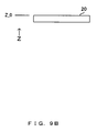
- a user touches a point a1 in the functional area S_A, and performs a drag operation (an operation for moving a finger up to a point a2 while touching the touch panel with the finger) up to the point a2 along the restriction frame 209.
- the microscope controller 2 instructs the stage Z driving controlling unit 22 via the microscope controlling unit 22 so that the stage gets closer to the objective lens 23.
- the stage 20 moves upward in FIG. 9B .
- the moving distance of the stage 20 in the Z direction corresponds to the distance of the drag operation performed in the functional area S_A on the touch panel 207. Accordingly, the microscope controller 2 instructs the microscope controlling unit 31 to move the stage 20 by a distance obtained by multiplying the distance dragged on the touch panel by a coefficient 1a.
- the point a5 that is a point in the vicinity of the protrusion 210a is pressed for a predetermined duration of t_a in the functional area S_A as illustrated in FIG. 13A .
- the microscope controller 2 controls the driving of the stage 20 so that the stage 20 draws apart from the objective lens 23. As a result, the stage 20 moves downward in FIG. 13B .
- the point a6 that is a point in the vicinity of the protrusion 210b is pressed for the predetermined duration of t_a as illustrated in FIG. 13A .
- the microscope controller 2 controls the driving of the stage 20 so that the stage 20 gets closer to the objective lens 23. As a result, the stage 20 moves upward in FIG. 13B .
- the coefficient 1a is a fixed value.
- the coefficient 1a may be switched. Namely, the coefficient 1a may be variable for each of the objective lenses 23.
- FIG. 14A icons 302a to 302e that respectively represent the objective lenses 23a to 23e attached to the motorized revolver 24 are depicted in the area S_B.
- FIG. 14A represents that the objective lens represented by the icon 302c is an objective lens currently inserted in the optical path, and is enlarged and displayed at the center.
- information of the objective lens 23c with 20x magnification is displayed.
- a user touches the vicinity of a point b1 illustrated in FIG. 14A in the functional area S_B, and performs a drag operation (an operation for moving the touch a finger toward a point b2 while touching the panel) toward the point b2 along the restriction frame 209, or performs an operation for quickly moving the finger toward the point b2 while touching the touch panel.
- a drag operation an operation for moving the touch a finger toward a point b2 while touching the panel
- the functional area S_B has a function of detecting a switching direction of an objective lens on the basis of a drag operation. Accordingly, a similar operation is performed also when a user touches the vicinity of the point b3 and performs a drag operation toward the point b2 along the restriction frame 209 as illustrated in FIG. 15A .
- the functional area S_B has the function of detecting a switching direction of an objective lens on the basis of a drag operation.
- the function of detecting a switching direction of an obj ective lens on the basis of a drag operation can be switched by pressing a function switching button 303 arranged in the functional area S_H as illustrated in FIG. 18A .
- FIG 17A when the function switching button 303 is pressed, the icons 302a to 302e displayed in the functional area S_B are respectively changed to icons 302a' to 302e' illustrated in FIG. 18A . With the press of any of the icons 302a' to 302e', switching can be directly made to a corresponding obj ective lens 23 ( FIG. 18B ).
- FIG. 18B illustrates the state where the objective lens 23d with 50x magnification is inserted in the optical path by a cursor indicating that 302d' is selected.
- the microscope controller 2 instructs the microscope controlling unit 31 so that the motorized revolver 24 performs a rotation control as illustrated in FIG. 19B .
- the motorized revolver 24 inserts the objective lens 23b with 10x magnification in the optical path by switching from the objective lens 23d with 50x magnification to the objective lens 23b with 10x magnification on the basis of this instruction.
- the functional area S_C supports a switching operation of the fluorescence cubes 35 attached to the motorized cube turret 25. Since this operation is similar to the above described switching operation of the objective lenses 23, its explanation is omitted.
- the functional area S_D is used as illustrated in FIG. 20 .
- FIG. 20 is an explanatory view of operations performed in the functional area S_D to which a function of controlling the dimming of the transmission illumination light source 6 or the epi-illumination light source 13 is assigned.
- the microscope controller 2 instructs the microscope controlling unit 31 so that the transmission illumination light source 6 or the epi-illumination light source 13 controls the dimming in accordance with the direction of the drag operation.
- FIG. 21 is a flow of operations of the microscope controller when a drag operation is performed in the functional area S_E in this embodiment.
- the touch panel controlling unit 206 detects X and Y coordinates of the position of the input (S112). The touch panel controlling unit 206 transmits the detected coordinate information to the CPU 201.
- the touch panel controlling unit 206 While the drag operation is being performed ("YES" in S113), the touch panel controlling unit 206 detects coordinates corresponding to the position being dragged (S114). The touch panel controlling unit 206 transmits the detected coordinate information to the CPU 201.
- the CPU 201 calculates a moving distance and a moving direction of the stage in accordance with the input coordinates and coordinates being dragged on the basis of the coordinate information transmitted from the touch panel controlling unit 206 (S115).
- the CPU 201 instructs the stage X driving controlling unit 21 via the microscope controlling unit 31 so that the stage is moved by a calculated distance in a calculated direction (S116). The processes in S114 to S116 are repeated until the drag operation is terminated.
- a control that the CPU 201 performs according to an operation of the touch panel 207 is described in detail below with reference to the flow illustrated in FIG. 21 . Operations of the stage 20 in the X-Y direction are described with reference to FIGs. 22 to 25 .
- the microscope controller 2 issues an instruction to the stage X driving controlling unit 21 via the microscope controlling unit 31. Then, the stage X driving controlling unit 21 controls the stage 20 so that the stage 20 is moved by a distance and a direction, which correspond to those of a drag operation, as illustrated in FIG. 22A ( FIG. 22B ).
- the moving distance of the stage 20 in the X-Y direction corresponds to the distance of the drag operation performed in the functional area S_E on the touch panel 207.
- the microscope controller 2 instructs the microscope controlling unit 31 so that the stage 20 moves by a distance obtained by multiplying the distance on the touch panel 20 by a coefficient le.
- the drag operation is performed by a distance XE in the X direction and by a distance YE in the Y direction from a point e1 to a point e2 as illustrated in FIG. 23A . Then, a control for moving the stage 20 by a distance XE ⁇ le from a coordinate X_0 to X_1 in the X direction is performed, and a control for moving the stage 20 by a distance YExle from a coordinate Y_0 to Y_1 in the Y direction is performed ( FIG. 23B ).
- a drag operation is performed by a distance XE' in the X direction and by a distance YE' in the Y direction from a point e3 to a point e4 as illustrated in FIG. 24A . Then, a control for moving the stage 20 by a distance XE' ⁇ le from the coordinate X_1 to X_2 in the X direction is performed, and a control for moving the stage 20 by a distance YE'xle from the coordinate Y_1 to Y_2 in the Y direction is performed ( FIG. 24B ) . During the drag operation, the position of the stage 20 moves with the position being dragged by detecting coordinates being dragged.
- the coefficient le may be varied according to the objective lens 23 currently inserted in the optical path. Moreover, the coefficient may be automatically set for a drag distance on the touch panel 207 so that the moving distance of the stage 20 when the objective lens 23a with low magnification is inserted becomes longer than that when the objective lens 23b with high magnification inserted, namely, so that the stage 20 moves in a field of view in the same way regardless of lens magnification.
- any of the microscope operational functions such as a coordinate, corresponding to a drag operation, of the stage 20 in the Z direction of the system, the amount of dimming of the light source, a magnification, the position of an optical element turret is arranged along the periphery of the touch panel.
- various types of operations of the microscope can be implemented by performing a drag operation along the periphery without looking away from the eyepiece lens 26.
- the protruding frame is provided on the surface of the touch panel, and an area enclosed by the protruding frame is assigned an operational function of the stage in the horizontal direction, whereby the operability of the microscope including the stage can be improved.
- the functional area S_E is arranged at the center of the touch panel 207 as illustrated in FIGs. 2A , 3A , 4A and 5A .
- the arrangement of the functional area S_E is not limited to this one.
- the functional area S_E may be arranged, for example, as illustrated in FIGs. 26A and 26B .
- FIG. 26A illustrates an example (No. 1) where the functional area S_E having the operational function of moving the stage 20 in the X-Y direction, the functional area S_A having the operational function of moving the stage 20 in the Z direction, and the functional area S_B having the operational function of switching among the objective lenses are arranged in the periphery of the touch panel 207.
- FIG. 26B illustrates an example (No. 2) where the functional area S_E having the operational function of moving the stage 20 in the X-Y direction, the functional area S_A having the operational function of moving the stage 20 in the Z direction, and the functional area S_B having the operational function of switching among the objective lenses are arranged in the periphery of the touch panel 207.
- not only the functional areas S_A and S_B but also the functional area S_E can be arranged in the periphery (restriction frame 209) of the touch panel 207.
- Such arrangement information can be implemented with the functional area setting information stored in the nonvolatile memory 204 as described with reference to FIG. 7 . Namely, coordinates of the functional areas S_A, S_B and S_E are set in the functional area setting information so that these functional areas can be arranged along the restriction frame 209.
- the CPU 201 reads the functional area setting information recorded in the nonvolatile memory 204 into the RAM 203 in S101 of FIG. 7 (S101).
- the CPU 201 sets the functional areas S_A, S_B and S_E by arranging these functional areas along the restriction frame 209 on the basis of the functional area setting information (S102). Subsequent operations are similar to those described with reference to FIG. 7 .
- the stage 20 can be moved in the X-Y direction along the periphery (restriction frame 209) of the touch panel 207. Consequently, the microscope operability of a user can be improved.
- an erected microscope apparatus is adopted as the microscope apparatus 1 in the above described microscope system according to the embodiment.
- the present invention is not limited to the inverted microscope apparatus.
- An inverted microscope apparatus may be adopted.
- this embodiment may be applicable to various types of systems such as a line apparatus including the microscope apparatus.
- This embodiment has referred to the changes in the coordinate of the stage 20 in the Z direction, the amount of dimming of the light source, magnifications, and the position of the optical element turret as assignments of the microscope functions.
- this embodiment is not limited to the above described changes in terms of sequentially driving portions of the microscope by continuously performing a drag operation along a positional marker part that is a protrusion or the like for identifying a functional area with a touch. Changes may be made, for example, to a field stop (FS), an aperture stop (AS) or other known motorized portions or units.
- FS field stop
- AS aperture stop
- This embodiment has referred to the switching among the objective lenses when needed in the microscope apparatus including the plurality of objective lenses.
- this embodiment is not limited to this configuration.
- zooming may be made when needed in a microscope apparatus including an objective lens having, for example, a zooming mechanism.
- the position of a functional area assigned on the touch panel can be identified with a touch by adopting a touch panel provided with a restriction frame, protrusions, and successive level differences.
- the configuration of the present invention is not limited to this embodiment in terms of identifying a functional area on a touch panel.
- a functional area on a touch panel may be identified with a finger touch of a person by using protrusions arranged at regular intervals, or materials having different frictional coefficients on the touch panel.
- the restriction frame, the protrusions and the like for identifying a functional area may be attachable/detachable to/from the microscope controller 2.
- a microscope controller having a touch panel is implemented in this embodiment.
- a device having a function equivalent to the touch panel may be replaceable.
- a microscope controller that can improve the microscope operability of a user, and a microscope system including the microscope controller can be provided.
Abstract
Description
- The present invention relates to a microscope system which includes a plurality of objective lenses, enlarges and observes a minute sample, and in which various optical members are respectively electrically-driven by electric driving device such as motors.
- Microscope apparatuses are widely used in studies, examinations and the like in a biological field in addition to an industrial field. An observation and an examination that are made with such a microscope apparatus are implemented by operating a motorized stage capable of moving a sample to be observed on a plane orthogonal to an observation optical path extending from an objective lens in the microscope apparatus including a plurality of objective lenses normally having different magnifications. When a sample is observed with such a microscope, various types of components (such as various types of illuminations, an aperture stop, a field stop, a revolver, an automatic focusing mechanism, a switching mechanism of optical elements such as a lens, a filter or the like), which configure a microscope, need to be operated according to an observation condition.
- As a technique for operating these components, for example, a method for connecting an operation device to a body of a microscope, for driving the components according to an operation performed for the operation device, and for grasping driven states of the components with a display made on the operation device is normally known. Namely, a controller dedicated to a microscope, or a microscope controller such as a PC (Personal Computer) or the like is connected to a body of a microscope via a communication cable. Then, a command is exchanged with the main body of the microscope according to an operation of the microscope controller, so that various types of settings are made by driving controls of the components.
- Examples of techniques related to a technique disclosed by this specification include
WO96/18924 2008-292578 - A microscope controller that performs an operation for controlling an operation of each motorized unit configuring a microscope system according to the present invention includes: a touch panel unit that accepts an input made with an external physical contact, and has a display function; a controlling unit for setting a display area as a functional area by assigning an image for operating the motorized unit to the certain display area of the touch panel unit, and for generating a control instruction signal for controlling the motorized unit in accordance with a contact operation performed for the motorized unit corresponding to the functional area upon detection of an input made in the functional area; and a communication controlling unit for transmitting the control instruction signal to an external device that controls an operation of the motorized unit.
- In the microscope controller, the controlling unit successively sets one or more functional areas in a predetermined range along a periphery of the touch panel unit, and generates a control instruction signal according to a drag operation performed in the functional area.
- In the microscope controller, the controlling unit assigns, to the one or more functional areas set along the periphery of the touch panel unit, at least any of a function of adjusting a coordinate of a motorized stage in an optical axis direction, a function of adjusting an amount of dimming of a light source unit, a function of adjusting an optical magnification by switching among objective lenses attached to a revolver unit, a function of switching among optical elements included in an optical element turret unit, and a function of adjusting a zoom magnification of a zooming mechanism.
- In the microscope controller, the controlling unit sets a functional area as a central functional area in an area enclosed by the functional areas set along the periphery of the touch panel unit, and generates a control instruction signal according to a drag operation performed in the central functional area.
- In the microscope controller, the controlling unit generates a control instruction signal for controlling a move of the motorized stage in a direction vertical to the optical axis direction in accordance with a drag operation performed in the central functional area.
- The microscope controller further comprises a positional marker part that is a physical marker at a predetermined position on the touch panel unit.
- In the microscope controller, the positional marker part is a frame-shaped convex part that has a predetermined height and is provided along the periphery of the touch panel unit, or a level difference formed between a flat surface of the touch panel unit when the touch panel unit is installed at a concave bottom provided on a predetermined surface of a housing of the microscope controller and the predetermined surface of the housing.
- In the microscope controller, one or more protrusions are formed on an inner wall side of the frame-shaped convex part, or on a side wall of the level difference.
- The microscope controller further comprises first and second positional marker parts that are physical markers at predetermined positions on the touch panel unit. In the microscope, the controlling unit successively sets one or more functional areas in a predetermined range along the periphery of the touch panel unit, and sets a functional area as a central functional area in an area enclosed by the functional areas set along the periphery of the touch panel unit, the first positional marker part is a first frame-shaped convex part that has a predetermined height and is provided along the periphery of the touch panel unit, or a first level difference formed between a flat surface of the touch panel unit when the touch panel unit is installed at a concave bottom provided on a predetermined surface of a housing of the microscope controller and the predetermined surface of the housing, and the second positional marker part is a second frame-shaped convex part that has a predetermined height and is provided, on the touch panel unit, along a border between the central functional area and the functional areas set along the periphery of the touch panel unit, or a second level difference formed between a surface including the central functional area and a surface including the functional areas.
- In the microscope controller, one or more protrusions are formed on at least any of an inner wall side of the first frame-shaped convex part or a side wall of the first level difference, and the second frame-shaped convex part or the second level difference.
- In the microscope controller, the second frame-shaped convex part is attachable/detachable to/from the touch panel unit. Furthermore, a microscope system includes the microscope controller.
-
-
FIG. 1 illustrates an example of a configuration of a microscope system according to an embodiment; -
FIG. 2A is a top view of a microscope controller (implementation example 1) according to this embodiment; -
FIG. 2B is a side view of the microscope controller (implementation example 1) according to this embodiment; -
FIG. 3A is a top view of a microscope controller (implementation example 2) according to this embodiment; -
FIG. 3B is a side view of the microscope controller (implementation example 2) according to this embodiment; -
FIG. 3C is a side view of the microscope controller (modification example 1 of the implementation example 2) according to this embodiment; -
FIG. 3D is a side view of the microscope controller (modification example 2 of the implementation example 2) according to this embodiment; -
FIG. 4A is a top view of a microscope controller (implementation example 3) according to this embodiment; -
FIG. 4B is a side view of the microscope controller (implementation example 3) according to this embodiment; -
FIG. 5A is a top view of a microscope controller (implementation example 4) according to this embodiment; -
FIG. 5B is a side view of the microscope controller (implementation example 4) according to this embodiment; -
FIG. 5C is a side view of the microscope controller (modification example 1 of the implementation example 4) according to this embodiment; -
FIG. 5D is a side view of the microscope controller (modification example 2 of the implementation example 4) according to this embodiment; -
FIG. 6 illustrates an overview of an internal configuration of the microscope controller according to this embodiment; -
FIG. 7 is a flow of a control of a microscope controller when a touch operation is performed on a functional area to which a function is assigned in this embodiment; -
FIG. 8 is an explanatory view of operations of a microscope system when a touch operation is performed on functional areas to which functions of operating a motorized unit configuring a microscope are respectively assigned in this embodiment; -
FIG. 9A is an explanatory view (No. 1) of an operation for a functional area S_A to which a function of moving a stage in a Z direction is assigned; -
FIG. 9B is an explanatory view (No. 1) of a move of the stage in the Z direction as a result of the operation; -
FIG. 10A is an explanatory view (No. 2) of an operation for the functional area S_A to which the function of moving the stage in the Z direction is assigned; -
FIG. 10B is an explanatory view (No. 2) of a move of the stage in the Z direction as a result of the operation; -
FIG. 11A is an explanatory view (No. 3) of an operation for the functional area S_A to which the function of moving the stage in the Z direction is assigned; -
FIG. 11B is an explanatory view (No. 3) of a move of the stage in the Z direction as a result of the operation; -
FIG. 12A is an explanatory view (No. 4) of an operation for the functional area S_A to which the function of moving the stage in the Z direction is assigned; -
FIG. 12B is an explanatory view (No. 4) of a move of the stage in the Z direction as a result of the operation; -
FIG. 13A is an explanatory view (No. 5) of an operation for the functional area S_A to which the function of moving the stage in the Z direction is assigned; -
FIG. 13B is an explanatory view (No. 5) of a move of the stage in the Z direction as a result of the operation; -
FIG. 14A is an explanatory view (No. 1) of an operation for a functional area S_B to which a function of switching among objective lenses with a motorized revolver is assigned; -
FIG. 14B is an explanatory view (No. 1) of positions of the objective lenses arranged on the motorized revolver as a result of the operation; -
FIG. 15A is an explanatory view (No. 2) of an operation for the functional area S_B to which the function of switching among the objective lenses with the motorized revolver is assigned; -
FIG. 15B is an explanatory view (No. 2) of positions of the objective lenses arranged on the motorized revolver as a result of the operation; -
FIG. 16A is an explanatory view (No. 3) of an operation for the functional area S_B to which the function of switching among objective lenses with the motorized revolver is assigned; -
FIG. 16B is an explanatory view (No. 3) of positions of the objective lenses arranged on the motorized revolver as a result of the operation; -
FIG. 17A is an explanatory view (No. 4) of an operation for the functional area S_B to which the function of switching among the objective lenses with the motorized revolver is assigned; -
FIG. 17B is an explanatory view (No. 4) of positions of the objective lenses arranged on themotorized revolver 24 as a result of the operation; -
FIG. 18A is an explanatory view (No. 5) of an operation for the functional area S_B to which the function of switching among the objective lenses with the motorized revolver is assigned; -
FIG. 18B is an explanatory view (No. 5) of positions of the objective lenses arranged on the motorized revolver as a result of the operation; -
FIG. 19A is an explanatory view (No. 6) of an operation for the functional area S_B to which the function of switching among the objective lenses with the motorized revolver is assigned; -
FIG. 19B is an explanatory view (No. 6) of positions of the objective lenses arranged on the motorized revolver as a result of the operation; -
FIG. 20 is an explanatory view of operations for a functional area S_D to which a function of controlling dimming of a transmission illumination light source or an epi-illumination light source is assigned; -
FIG. 21 is a flow of operations of a microscope controller when a drag operation is performed in a functional area S_E in this embodiment; -
FIG. 22A is an explanatory view (No. 1) of an operation for the functional area S_E to which a function of moving the stage in an X-Y direction is assigned; -
FIG. 22B is an explanatory view (No. 2) of a move of the stage in the X-Y direction as a result of the operation; -
FIG. 23A is an explanatory view (No. 2) of an operation for the functional area S_E to which the function of moving the stage in the X-Y direction is assigned; -
FIG. 23B is an explanatory view (No. 2) of a move of the stage in the X-Y direction as a result of the operation; -
FIG. 24A is an explanatory view (No. 3) of an operation for the functional area S_E to which the function of moving the stage in the X-Y direction is assigned; -
FIG. 24B is an explanatory view (No. 3) of a move of the stage in the X-Y direction as a result of the operation; -
FIG. 25A is an explanatory view (No. 4) of an operation for the functional area S_E to which the function of moving the stage in the X-Y direction is assigned; -
FIG. 25B is an explanatory view (No. 4) of a move of the stage in the X-Y direction as a result of the operation; -
FIG. 26A illustrates an example (No. 1) where the functional area S_E having an operational function of moving the stage in the X-Y direction, the functional area S_A having an operational function of moving the stage in the Z direction, and the functional area S_B having an operational function of switching among objective lenses are arranged in a periphery of a touch panel; and -
FIG. 26B illustrates an example (No. 2) where the functional area S-E having the operational function of moving the stage in the X-Y direction, the functional area S_A having the operational function of moving the stage in the Z direction, and the functional area S_B having the operational function of switching among the objective lenses are arranged in the periphery of the touch panel. - In recent years, microscope controllers having a touch panel function to support various operations have been marketed. Namely, microscope controllers are used to operate a microscope by arranging arbitrary button areas on a touch panel, and by pressing the button areas.
- For such touch panel controllers, however, an operational screen is configured by arranging contents equivalent to a PC operational screen unchanged. Especially, blind touch operations are not taken into account. Therefore, when an observer operates a button, he or she needs to verify the position of the button by once looking away from an eyepiece lens. This deteriorates microscope operability.
- In consideration of the above described problem, an embodiment of the present invention provides a microscope controller that can improve the microscope operability of a user, and also provides a microscope system including the microscope controller.
- The microscope controller that performs operations for controlling operations of motorized units configuring a microscope system according to an embodiment of the present invention includes a touch panel unit, a controlling unit, and a communication controlling unit.
- The touch panel unit accepts an input externally made with a physical contact, and has a display function. The touch panel unit corresponds to, for example, a
touch panel unit 207 in this embodiment. - The controlling unit sets a certain display area as a functional area by assigning an image for operating a motorized unit to the display area of the touch panel unit. In addition, the controlling unit generates a control instruction signal for controlling the motorized unit in accordance with a contact operation performed for the motorized unit corresponding to the functional area upon detection of an input made to the functional area. The controlling unit corresponds to, for example, a
CPU 201 in this embodiment. - The communication controlling unit transmits the control instruction signal to an external device that controls the operations of the motorized unit. The communication controlling unit corresponds to, for example, a
communication controlling unit 205 in this embodiment. - With this configuration, the microscope operability of a user can be improved.
- The controlling unit can successively set one or more functional areas in a predetermined range along a periphery of the touch panel unit, and can generate a control instruction signal according to a drag operation performed in the functional areas.
- With this configuration, the position of a functional area set on the touch panel can be accurately grasped when a finger is moved along the periphery of the touch panel unit.
- The controlling unit may assign, to the functional areas set along the periphery of the touch panel unit, at least any of a function of adjusting a coordinate of the motorized stage in an optical axis direction, a function of adjusting the amount of dimming of a light source unit, a function of adjusting an optical magnification by switching among objective lenses attached to a revolver unit, a function of switching among optical elements included in an optical element turret unit, and a function of adjusting a zoom magnification of a zooming mechanism.
- With this configuration, various types of operations of the microscope can be implemented by performing a drag operation along the periphery without looking away from the
eyepiece lens 26. - Additionally, the controlling unit sets a functional area as a central functional area (for example, an area denoted with S_E in this embodiment) in an area enclosed by the functional areas set along the periphery of the touch panel unit, and generates a control instruction signal according to a drag operation performed in the central functional area. Specifically, the controlling unit generates a control instruction signal for controlling a move of the motorized stage in a direction vertical to an optical axis direction of the motorized stage in accordance with a drag operation performed in the central functional area.
- With this configuration, the motorized stage can be moved on an X-Y plane.
- The microscope controller further includes a positional marker part that is a physical marker at a predetermined position on the touch panel. The positional marker part is a frame-shaped convex part (for example, a
restriction frame 209 in this embodiment) that has a predetermined height and is provided along the periphery of the touch panel unit, or a level difference (for example, alevel difference 209a in this embodiment) formed between a flat surface of the touch panel unit when the touch panel unit is installed at a concave bottom provided on a predetermined surface of a housing of the microscope controller and a predetermined surface of the housing. - With this configuration, the position of a functional area set on the touch panel can be accurately grasped when a finger is moved along the restriction frame or the level difference.
- Note that one or more protrusions may be formed on an inner wall side of the frame-shaped convex part, or on a side wall of the level difference. With this configuration, the position of a functional area set on the touch panel can be more accurately grasped.
- Additionally, the microscope controller may include first and second positional marker parts that are physical markers at predetermined positions of the touch panel unit. In this case, the controlling unit successively sets one or more functional areas in a predetermined range along the periphery of the touch panel unit. At the same time, the controlling unit sets a functional area as a central functional area in an area enclosed by the functional areas set along the periphery of the touch panel unit. At this time, the first positional marker part is a first frame-shaped convex part (for example, the
restriction frame 209 in this embodiment) that has a predetermined height and is provided along the periphery of the touch panel unit, or a first level difference (for example, thelevel difference 209a in this embodiment) formed between a flat surface of the touch panel unit when the touch panel unit is installed at a concave bottom provided on a predetermined surface of a housing of the microscope controller and a predetermined surface of the housing. The second positional marker part is a second frame-shaped convex part (for example, a protrudingframe 209 in this embodiment) that has a predetermined height and is provided along a boundary between the central functional area on the touch panel unit and the functional areas set along the periphery of the touch panel unit, or a second level difference (for example, alevel difference 211a in this embodiment) formed between a surface including the central functional area and a surface including the functional areas. - With this configuration, the position of a functional area set on the touch panel can be accurately grasped when a finger is moved along the restriction frame, the protruding frame, or the level difference.
- Additionally, one or more protrusions may be formed on at least any of an inner wall side of the first frame-shaped convex part or a side wall of the first level difference, and the second frame-shaped convex part or the second level difference. With this configuration, the position of a functional area set on the touch panel can be more accurately grasped.
- Furthermore, the second frame-shaped convex part may be detachable from the touch panel unit. With this configuration, the protruding frame can be detached when necessary. Moreover, a microscope system may include the microscope controller.
-
FIG. 1 illustrates an example of a configuration of the microscope system according to this embodiment. Amicroscope apparatus 1 includes, as a transmission observation optical system, a transmission illumination light source 6, a collector lens 7 for collecting illumination light of the transmission illumination light source 6, atransmission filter unit 8, atransmission field stop 9, atransmission aperture stop 10, a condenser optical element unit 11, and a top lens unit 12. - Additionally, the
microscope apparatus 1 includes, as an epi-observation optical system, an epi-illumination light source 13, acollector lens 14, anepi filter unit 15, anepi shutter 16, anepi field stop 17, and anepi aperture stop 18. - Furthermore, a
motorized stage 20 on which asample 19 is put is provided in an observation optical path where an optical path of the transmission observation optical system and that of the epi observation optical path overlap. Themotorized stage 20 can be moved in an upward/downward (Z) direction, and in right and left (X-Y) directions. - A move of the
motorized stage 20 is controlled by a stage X-Y driving controllingunit 21 and a stage Zdriving controlling unit 22. The stage X-Y driving controllingunit 21 moves thestage 20 in the X and the Y directions by controlling driving of an X-Y motor 21a. The stage Zdriving controlling unit 22 moves thestage 20 in the Z direction by controlling driving of aZ motor 22a. - The
motorized stage 20 has a function (not illustrated) of detecting an origin with an origin sensor. Therefore, coordinates of thesample 19 put on themotorized stage 20 can be detected, and the move of themotorized stage 20 can be controlled with a coordinate specification. - Additionally, a
revolver 24, acube turret 25, and abeam splitter 27 are provided in the observation optical path. - The
revolver 24 is provided with a plurality ofobjective lenses revolver 24, any of the plurality of objective lenses 23 can be selected and used for an observation. - A fluorescence cube A (35a), a fluorescence cube B (35b), and a fluorescence cube C (not illustrated) respectively have an excitation filter, a dichroic mirror, and an absorption filter corresponding to each fluorescent observation wavelength. With the
cube turret 25, switching can be made to any of the fluorescence cubes A (35a), B (35b), C (not illustrated),..., and the switched fluorescence cube can be arranged in the optical path. - The observation optical path is branched by the
beam splitter 27 to the side of theeyepiece lens 26 and the side of a video camera (not illustrated). - Furthermore, a
polarizer 28 for a differential interference observation, a DIC (Differential Interference Contrast)prism 29, and ananalyzer 30 can be inserted in the observation optical path. - These units are motorized, and operations thereof are controlled by a
microscope controlling unit 31 described below. - The
microscope controlling unit 31 is connected to themicroscope controller 2. Themicroscope controlling unit 31 has a function of controlling operations of theentire microscope apparatus 1. Themicroscope controlling unit 31 changes a microscopy, and dims the transmission illumination light source 6 and the epi-illumination light source 13 in accordance with a control signal or a command from themicroscope controller 2. Moreover, themicroscope controlling unit 31 has a function of transmitting the current state of the microscopy made by themicroscope apparatus 1 to themicroscope controller 2. Themicroscope controlling unit 31 is connected also to the stage X-Y driving controllingunit 21, and the stage Zdriving controlling unit 22. Accordingly, themotorized stage 20 can be controlled by themicroscope controller 2 via themicroscope controlling unit 31. -
FIGs. 2 to 5 illustrate variations of the microscope controller according to this embodiment. Themicroscope controller 2 is a controller having atouch panel 207 on which a user actually makes an input for an operation of themicroscope 1. - To a certain area on the
touch panel 207, a predetermined attribute for operating themicroscope system 1 is assigned. A user can perform various types of operations of the microscope by operating functional areas (GUI (Graphical User Interface) buttons or the like displayed on the touch panel) to which predetermined attributes are respectively assigned. The microscope controllers illustrated inFIGs. 2 to 5 are respectively described below. -
FIG. 2A is a top view of a microscope controller 2 (implementation example 1) according to this embodiment.FIG. 2B is a side view of the microscope controller 2 (implementation example 1) according to this embodiment. Thetouch panel 207 functions both as a display device and an input device. Thetouch panel 207 is fit into anouter housing 208 of themicroscope controller 2 as illustrated inFIG. 2A . - The
touch panel 207 is installed at a concave bottom of theouter housing 208. Alevel difference 209a is provided between a surface of thetouch panel 207 and an outer surface of theouter housing 208. - Here, functions can be respectively assigned to areas (functional areas) denoted with S_A, S_B, S_C and S_D on the
touch panel 207. As a result, thelevel difference 209a serves as a guide when a finger is moved along thelevel difference 209a. Accordingly, the positions of the functional areas denoted with S_A, S_B, S_C and S_D can be grasped along thelevel difference 209a. - Additionally, areas denoted with S_F, S_G, S_H and S_I are functional areas arranged at corners of the
touch panel 207. Moreover, a functional area S_E is arranged in a range enclosed by S_A, S_B, S_C and S_D. -
FIG. 3A is a top view of a microscope controller 2 (implementation example 2) according to this embodiment.FIG. 3B is a side view of the microscope controller 2 (implementation example 2) according to this embodiment. Themicroscope controller 2 illustrated inFIGs. 3A and 3B is configured by providing one ormore protrusions 210 on therestriction frame 209 illustrated inFIGs. 2A and 2B , and by providing a protrudingframe 211. - The
protrusions 210 are of size that a user can recognize when the user moves thetouch panel 207 with his or her finger along thelevel difference 209a. Therefore, thelevel difference 209a and theprotrusions 210 serve as a guide when the finger is moved along thelevel difference 209a. Accordingly, compared with the case illustrated inFIGs. 2A and 2B , the positions of the functional areas denoted with S_A, S_B, S_C and S_D can be more accurately grasped along thelevel difference 209a based on the positions of theprotrusions 210. - Additionally, with the
protrusions 210 and the corners of thetouch panel 207, the positions of the functional areas that are denoted with S_F, S_G, S_H and S_I and enclosed by theprotrusions 210 and the corners can be more clearly grasped. - Furthermore, the protruding
frame 211 that is provided on the touch panel separates the functional area S_E from the other functional areas. Therefore, the protrudingframe 211 serves as a guide. Accordingly, compared with the case illustrated inFIGs. 2A and 2B , the position of the functional area enclosed by the protrudingframe 211 can be made clearer, and the position of the functional area S_E can be more accurately grasped. - As illustrated in
FIGs. 3C and 3D , thearea 207b denoted with S_E may be provided at a position lower or higher than theareas 207a composed of S_A, S_B, S_C, S_D, S_F, S_G, S_H and S_I, and aresultant level difference 211a may be used as the protrudingframe 211. -
FIG. 4A is a top view of a microscope controller 2 (implementation example 3) according to this embodiment.FIG. 4B is a side view of the microscope controller 2 (implementation example 3) according to this embodiment. InFIGs. 2A, 2B ,3A and 3B , thetouch panel 207 is installed at the concave bottom of theouter housing 208. In the meantime, inFIG. 4B , there is no level difference between the surface of thetouch panel 207 and that of theouter housing 208, and only therestriction frame 209 that has a predetermined height and is provided at a boundary between thetouch panel 207 and theouter housing 208 is provided. Therestriction frame 209 is provided along the outline of the touch panel. Also with this configuration, effects similar to those ofFIGs. 2A and 2B can be achieved. -
FIG. 5A is a top view of a microscope controller 2 (implementation example 4) according to this embodiment.FIG. 5B is a side view of the microscope controller 2 (implementation example 4) according to this embodiment. Themicroscope controller 2 illustrated inFIGs. 5A and 5B is configured by providing one ormore protrusions 210 on therestriction frame 209 illustrated inFIGs. 4A and 4B , and by providing the protrudingframe 211. - Since the functions of the
protrusions 210 and the protruding frame 11 are similar to those described inFIGs. 3A and 3B , their explanations are omitted. InFIGs. 3A and5A , only therestriction frame 209 and the protrudingframe 211 may be provided without arranging theprotrusions 210. Alternatively, theprotrusions 210 may be provided on therestriction frame 209 inFIGs. 2A and4A . - As illustrated in
FIGs. 5C and 5D , thearea 207b denoted with S_E may be provided at a position lower or higher than theareas 207a composed of S_A, S_B, S_C, S_D, S_F, S_G, S_H, and S_I, and aresultant level difference 211a may be used as the protrudingframe 211. -
FIG. 6 illustrates an overview of an internal configuration of themicroscope controller 2 according to this embodiment. Themicroscope controller 2 includes a CPU (Central Processing Unit) 201, a RAM (Random Access Memory) 202, a ROM (Read Only Memory) 203, anonvolatile memory 204, acommunication controlling unit 205, a touchpanel controlling unit 206, and atouch panel 207. Various types of data can be mutually exchanged among these components via a bus under the control of theCPU 201. - The
CPU 201 controls the operations of theentire microscope controller 2. TheRAM 202 is a memory used by theCPU 201 as a working storage area when theCPU 201 executes a control program, and is a memory used to temporarily store various types of data. TheROM 203 prestores a control program that theCPU 201 executes to control the operations of themicroscope controller 2. Note that also application software for controlling themicroscope apparatus 1 is part of the control program. - The
nonvolatile memory 204 prestores information about a plurality of functional areas (functional area setting information), including an operational button display (icon button display or the like), to which predetermined attributes for operating themicroscope 1 are respectively assigned. Specifically, the functional area setting information is information that makes an association between coordinate information on the touch panel, which indicates a range of a functional area, and information about a function assigned to the functional area in order to operate a certain motorized unit configuring the microscope system. For example, for an operation of thestage 20, the function assigned to the functional area in order to operate a motorized unit is a function of moving thestage 20 in an X-Y direction, or a function of moving thestage 20 in a Z direction. Moreover, for an operation of themotorized revolver 24, the function assigned to the functional area in order to operate a motorized unit is a function of selecting an arbitrary objective lens by rotating the motorized revolver and of inserting the selected lens in the observation optical path. - The
communication controlling unit 205 manages a data communication (such as a serial communication) with themicroscope controlling unit 31 of the main body of themicroscope apparatus 1, and transmits control information for controlling the operations of the components and other information to themicroscope controlling unit 31. - The
touch panel 207 may be of any touch panel types such as a film resistor type, a capacitance type, an infrared ray type, an ultrasound type, or the like, and the type of thetouch panel 207 is not limited. Moreover, the touchpanel controlling unit 206 detects X and Y coordinates of a position input by a user on thetouch panel 207, and transmits the detected coordinate information to theCPU 201. -
FIG. 7 is a control flow of themicroscope controller 2 when a touch operation is performed on a functional area to which a function is assigned in this embodiment. TheCPU 201 that is a controlling unit of themicroscope controller 2 reads an application program stored in theROM 202, and executes the following process. - Initially, the
CPU 201 reads functional area setting information recorded in thenonvolatile memory 204 into the RAM 203 (S101). TheCPU 201 sets functional areas by respectively assigning attributes for operating themicroscope system 1 to the functional areas (including GUI buttons, etc. displayed on the touch panel) on thetouch panel 207 on the basis of the functional area setting information (S102). - For example, a functional area represented with coordinates (x1,y1) to (x2,y2) on the touch panel is represented as S_A. A functional area represented with coordinates (x3,y3) to (x4,y4) is represented as S_B. A functional area represented with coordinates (x5,y5) to (x6,y6) is represented as S_C. A functional area represented with coordinates (x7, y7) to (x8, y8) is represented as S_D. A functional area represented with coordinates (x9,y9) to (x10,y10) is represented as S_E. A functional area represented with coordinates (x11,y11) to (x12,y12) is represented as S_F. A functional area represented with coordinates (x13,y13) to (x14,y14) is represented as S_G. A functional area represented with coordinates (x15,y15) to (x16,y16) is represented as S_H. A functional area represented with coordinates (x17,y17) to (x18,y18) is represented as S_I. In this case, the functional area setting information is configured by making an association between each of the functional areas represented with the above coordinates and information about a function assigned to the corresponding functional area.
- For example, as illustrated in
FIG. 8 , theCPU 201 assigns a function of operating thestage 20 of themicroscope 1 in the Z direction to the functional area S_A on the basis of the functional area setting information. TheCPU 201 assigns a function of operating themotorized revolver 24 that switches among theobjective lenses 24 to the functional area S_B on the basis of the functional area setting information. TheCPU 201 assigns a function of operating theturret 25 that switches among the cubes 35 to the functional area S_C on the basis of the functional area setting information. TheCPU 201 assigns a function of dimming a light source to the functional area S_D on the basis of the functional area setting information. TheCPU 201 assigns a function of operating thestage 20 in the X-Y direction to the functional area S_E on the basis of the functional area setting information. - When an input is made on the
touch panel 207, the touchpanel controlling unit 206 detects X and Y coordinates of the position of the input on the touch panel 207 ("YES" in S103). The touchpanel controlling unit 206 then transmits the detected coordinate information to theCPU 201. - The
CPU 201 determines, on the basis of the functional area setting information, to which functional area the coordinate information transmitted from the touchpanel controlling unit 206 belongs, namely, to which function area the input is made (S104). - The
CPU 201 executes a control process according to the corresponding functional area on the basis of a determination result (S105) . For example, if the input is made to an arbitrary position in a certain functional area, theCPU 201 controls a display form of an image on a GUI according to coordinate information based on the touch operation. For example, theCPU 201 moves a corresponding image to the position of the input, changes the size of the image, changes a color of the image, changes a shape of the image, or moves a cursor. - Additionally, the
CPU 201 calculates an amount of a move on the touch panel according to the coordinate information based on the touch operation. Then, theCPU 201 converts the amount of a move into an amount of driving of the motorized unit assigned to the functional area, and transmits a control instruction signal to themicroscope controlling unit 31. Moreover, theCPU 201 transmits content selected on the touch panel according to the coordinate information based on the touch operation to themicroscope controlling unit 31 as a control instruction signal. TheCPU 201 repeats the processes in S103 to S105 until an observation is terminated (S106). - A control that the
CPU 201 performs for the processes in S103 to S105 of the flow illustrated inFIG. 7 according to an operation on thetouch panel 207 is described in detail below. For the sake of convenience of explanation, the following explanation is provided by taking the above described implementation example 4 (FIGs. 5A and 5B ). However, the control of theCPU 201 is not limited to this one, and may be performed for the other implementation examples. - An operation of the
stage 20 in the Z direction is initially described with reference toFIGs. 8 to 13 . InFIG. 8 , abar 301 represents a position of a coordinate in the Z direction. As a slider of thebar 301 rises toward the top inFIG. 9A , thestage 20 gets closer to the objective lens 23. As the slider falls inFIG. 9A , thestage 20 draws apart from the objective lens 23. - In
FIG. 9A , a user touches a point a1 in the functional area S_A, and performs a drag operation (an operation for moving a finger up to a point a2 while touching the touch panel with the finger) up to the point a2 along therestriction frame 209. Then, themicroscope controller 2 instructs the stage Zdriving controlling unit 22 via themicroscope controlling unit 22 so that the stage gets closer to the objective lens 23. As a result, thestage 20 moves upward inFIG. 9B . - Alternatively, in
FIG. 9A , the user touches the point a2 in the functional area S_A, and performs a drag operation up to the point a1 along therestriction frame 209. As a result, themicroscope controller 2 instructs the stage Zdriving controlling unit 22 via themicroscope controlling unit 31 so that thestage 20 draws apart from the objective lens 23. As a result, thestage 20 moves downward inFIG. 9B . - As described above, the moving distance of the
stage 20 in the Z direction corresponds to the distance of the drag operation performed in the functional area S_A on thetouch panel 207. Accordingly, themicroscope controller 2 instructs themicroscope controlling unit 31 to move thestage 20 by a distance obtained by multiplying the distance dragged on the touch panel by a coefficient 1a. - Here, if the drag operation is performed from the point a1 to the point a2 by a distance ZA as illustrated in
FIG. 10A , a control for moving thestage 20 toward the objective lens 23 from a coordinate Z_0 to a coordinate Z_1 by a distance ZA×1a is performed (FIG. 10B ). - If the drag operation is performed from a point a3 to a point a4 by a distance ZA' as illustrated in
FIG. 11A in the state illustrated inFIG. 10B , a control for further moving thestage 20 toward the objective lens 23 from the coordinate Z_1 to a coordinate Z_2 by a distance ZA×1a is performed (FIG. 11B ). Note that the position of thestage 20 moves with the position being dragged during the drag operation. - If the drag operation is performed from a point a6 to a point a5 in a reverse direction by a distance ZA" as illustrated in
FIG. 12A in the state illustrated inFIG. 11B , a control is performed so that thestage 20 draws apart from the objective lens 23 from the coordinate Z_2 to a coordinate Z_3 by a distance ZA"x1a (FIG. 12B ). - Furthermore, the point a5 that is a point in the vicinity of the
protrusion 210a is pressed for a predetermined duration of t_a in the functional area S_A as illustrated inFIG. 13A . Then, themicroscope controller 2 controls the driving of thestage 20 so that thestage 20 draws apart from the objective lens 23. As a result, thestage 20 moves downward inFIG. 13B . Moreover, the point a6 that is a point in the vicinity of theprotrusion 210b is pressed for the predetermined duration of t_a as illustrated inFIG. 13A . Then, themicroscope controller 2 controls the driving of thestage 20 so that thestage 20 gets closer to the objective lens 23. As a result, thestage 20 moves upward inFIG. 13B . - This embodiment has been described by assuming that the coefficient 1a is a fixed value. However, the coefficient 1a may be switched. Namely, the coefficient 1a may be variable for each of the objective lenses 23.
- Switching operations of the
motorized revolver 24 are described next with reference toFIGs. 14 to 19 . A case where anobjective lens 23a with 5x magnification, anobjective lens 23b with 10x magnification, anobjective lens 23c with 20x magnification, an objective lens 24d with 50x magnification, and anobjective lens 23e with 100x magnification are attached to themotorized revolver 24, and theobjective lens 23c with 20x magnification is inserted in the optical axis as illustrated inFIG. 14B is described. - As illustrated in
FIG. 14A ,icons 302a to 302e that respectively represent theobjective lenses 23a to 23e attached to themotorized revolver 24 are depicted in the area S_B.FIG. 14A represents that the objective lens represented by theicon 302c is an objective lens currently inserted in the optical path, and is enlarged and displayed at the center. Here, information of theobjective lens 23c with 20x magnification is displayed. - A user touches the vicinity of a point b1 illustrated in
FIG. 14A in the functional area S_B, and performs a drag operation (an operation for moving the touch a finger toward a point b2 while touching the panel) toward the point b2 along therestriction frame 209, or performs an operation for quickly moving the finger toward the point b2 while touching the touch panel. - Then, the
microscope controller 2 instructs themicroscope controlling unit 31 so that themotorized revolver 24 performs a rotation control. As illustrated inFIG. 15B , themotorized revolver 24 inserts theobjective lens 23d with 50x magnification in the optical path by switching from theobjective lens 23c with 20x magnification to theobjective lens 23d with 50x magnification. Then, a display of the icon that represents the objective lens currently inserted in the optical path is switched from the icon 302 to the icon that represents theobjective lens 23d with 50x magnification. - The functional area S_B has a function of detecting a switching direction of an objective lens on the basis of a drag operation. Accordingly, a similar operation is performed also when a user touches the vicinity of the point b3 and performs a drag operation toward the point b2 along the
restriction frame 209 as illustrated inFIG. 15A . - The user again touches the point b1 in the functional area S_B in the state illustrated in
FIG. 15A , and performs a drag operation toward the point b2 along therestriction frame 209. Then, themicroscope controller 2 instructs themicroscope controlling unit 31 so that themotorized revolver 24 performs a rotation control. As illustrated inFIG. 16B , themotorized revolver 24 inserts theobjective lens 23e with 100x magnification in the optical path by switching from theobjective lens 23d with 50x magnification to theobjective lens 23e with 100x magnification. A display of the icon 302 that represents the objective lens currently inserted in the optical path is switched from 302c to theicon 302e that represents theobjective lens 23e with 100x magnification (FIG. 16A ). - The user touches the point b2 in the functional area S_B in the state illustrated in
FIG. 16A , and performs a drag operation toward the point b1 along therestriction frame 209. Then, themicroscope controller 2 instructs themicroscope controlling unit 31 so that themotorized revolver 24 performs a rotation control. As illustrated inFIG. 17B , themotorized revolver 24 inserts theobjective lens 23d with 50x magnification in the optical path by switching from theobjective lens 23e with 100x magnification to theobjective lens 23d with 50x magnification. Then, a display of the icon 302 that represents the objective lens currently inserted in the optical path is switched from 302c to theicon 302d that represents theobjective lens 23d with 50x magnification (FIG. 17A ). - The functional area S_B has the function of detecting a switching direction of an objective lens on the basis of a drag operation. The function of detecting a switching direction of an obj ective lens on the basis of a drag operation can be switched by pressing a
function switching button 303 arranged in the functional area S_H as illustrated inFIG. 18A . - In
FIG 17A , when thefunction switching button 303 is pressed, theicons 302a to 302e displayed in the functional area S_B are respectively changed toicons 302a' to 302e' illustrated inFIG. 18A . With the press of any of theicons 302a' to 302e', switching can be directly made to a corresponding obj ective lens 23 (FIG. 18B ). - The icon of the objective lens inserted in the optical path is distinguishable from the other icons. Here,
FIG. 18B illustrates the state where theobjective lens 23d with 50x magnification is inserted in the optical path by a cursor indicating that 302d' is selected. - When the
icon 302b' is pressed inFIG. 18A , themicroscope controller 2 instructs themicroscope controlling unit 31 so that themotorized revolver 24 performs a rotation control as illustrated inFIG. 19B . Themotorized revolver 24 inserts theobjective lens 23b with 10x magnification in the optical path by switching from theobjective lens 23d with 50x magnification to theobjective lens 23b with 10x magnification on the basis of this instruction. - The functional area S_C supports a switching operation of the fluorescence cubes 35 attached to the
motorized cube turret 25. Since this operation is similar to the above described switching operation of the objective lenses 23, its explanation is omitted. - For dimming operations of the transmission illumination light source 6 and the epi-
illumination light source 13, which are controlled by themicroscope controlling unit 31, the functional area S_D is used as illustrated inFIG. 20 . -
FIG. 20 is an explanatory view of operations performed in the functional area S_D to which a function of controlling the dimming of the transmission illumination light source 6 or the epi-illumination light source 13 is assigned. By performing a drag operation from d1 toward d2 in the functional area S_D in a similar manner as in the above described functional area S_A, a control for increasing the amount of light can be performed. Moreover, by performing a drag operation from d2 toward d1, a control for decreasing the amount of light can be performed. - For example, if a drag operation is performed in the functional area S_D, the
microscope controller 2 instructs themicroscope controlling unit 31 so that the transmission illumination light source 6 or the epi-illumination light source 13 controls the dimming in accordance with the direction of the drag operation. - As a slider of the
bar 305 becomes closer to the right, the amount of light increases. As the slider becomes closer to the left, the amount of light decreases. Each time thebutton 306 is pressed, switching can be made between the dimming of the transmission illumination light source 6 and that of the epi-illumination light source 13. - Operations of the
stage 20 in the X-Y direction are described next. -
FIG. 21 is a flow of operations of the microscope controller when a drag operation is performed in the functional area S_E in this embodiment. When a user performs a drag operation in the functional area S_E inFIG. 22A ("YES" in S111), the touchpanel controlling unit 206 detects X and Y coordinates of the position of the input (S112). The touchpanel controlling unit 206 transmits the detected coordinate information to theCPU 201. - While the drag operation is being performed ("YES" in S113), the touch
panel controlling unit 206 detects coordinates corresponding to the position being dragged (S114). The touchpanel controlling unit 206 transmits the detected coordinate information to theCPU 201. - The
CPU 201 calculates a moving distance and a moving direction of the stage in accordance with the input coordinates and coordinates being dragged on the basis of the coordinate information transmitted from the touch panel controlling unit 206 (S115). - The
CPU 201 instructs the stage X driving controllingunit 21 via themicroscope controlling unit 31 so that the stage is moved by a calculated distance in a calculated direction (S116). The processes in S114 to S116 are repeated until the drag operation is terminated. - If no input is made in the functional area S_E ("NO" in S111) or if a drag operation is not being performed ("NO" in S113), whether or not to terminate an observation is determined (S117). If the observation is determined to continue, the flow goes back to S111.
- A control that the
CPU 201 performs according to an operation of thetouch panel 207 is described in detail below with reference to the flow illustrated inFIG. 21 . Operations of thestage 20 in the X-Y direction are described with reference toFIGs. 22 to 25 . - The
microscope controller 2 issues an instruction to the stage X driving controllingunit 21 via themicroscope controlling unit 31. Then, the stage X driving controllingunit 21 controls thestage 20 so that thestage 20 is moved by a distance and a direction, which correspond to those of a drag operation, as illustrated inFIG. 22A (FIG. 22B ). - The moving distance of the
stage 20 in the X-Y direction corresponds to the distance of the drag operation performed in the functional area S_E on thetouch panel 207. Themicroscope controller 2 instructs themicroscope controlling unit 31 so that thestage 20 moves by a distance obtained by multiplying the distance on thetouch panel 20 by a coefficient le. - Here, the drag operation is performed by a distance XE in the X direction and by a distance YE in the Y direction from a point e1 to a point e2 as illustrated in
FIG. 23A . Then, a control for moving thestage 20 by a distance XE×le from a coordinate X_0 to X_1 in the X direction is performed, and a control for moving thestage 20 by a distance YExle from a coordinate Y_0 to Y_1 in the Y direction is performed (FIG. 23B ). - Furthermore, a drag operation is performed by a distance XE' in the X direction and by a distance YE' in the Y direction from a point e3 to a point e4 as illustrated in
FIG. 24A . Then, a control for moving thestage 20 by a distance XE' ×le from the coordinate X_1 to X_2 in the X direction is performed, and a control for moving thestage 20 by a distance YE'xle from the coordinate Y_1 to Y_2 in the Y direction is performed (FIG. 24B ) . During the drag operation, the position of thestage 20 moves with the position being dragged by detecting coordinates being dragged. - A button 304 arranged in the functional area S_F has a function of switching a moving sensitivity of the stage. Namely, when the button 304 is pressed, the coefficient le is changed to le'. In this embodiment, le' is a value of one tenth of le. At this time, if a drag operation is performed from the point e3 to the point e4 by a distance XE' in the X direction and by a distance YE' in the Y direction in
FIG. 25A after the button 304 is pressed, the moving distance of thestage 20 can be reduced to a distance of one tenth of the moving distance illustrated inFIG. 24B as a slightly moving operation as illustrated inFIG. 25B . - The coefficient le may be varied according to the objective lens 23 currently inserted in the optical path. Moreover, the coefficient may be automatically set for a drag distance on the
touch panel 207 so that the moving distance of thestage 20 when theobjective lens 23a with low magnification is inserted becomes longer than that when theobjective lens 23b with high magnification inserted, namely, so that thestage 20 moves in a field of view in the same way regardless of lens magnification. - As described above, in the microscope system according to this embodiment, any of the microscope operational functions such as a coordinate, corresponding to a drag operation, of the
stage 20 in the Z direction of the system, the amount of dimming of the light source, a magnification, the position of an optical element turret is arranged along the periphery of the touch panel. With this arrangement, various types of operations of the microscope can be implemented by performing a drag operation along the periphery without looking away from theeyepiece lens 26. Moreover, the protruding frame is provided on the surface of the touch panel, and an area enclosed by the protruding frame is assigned an operational function of the stage in the horizontal direction, whereby the operability of the microscope including the stage can be improved. - In the above described embodiment, the functional area S_E is arranged at the center of the
touch panel 207 as illustrated inFIGs. 2A ,3A ,4A and5A . However, the arrangement of the functional area S_E is not limited to this one. The functional area S_E may be arranged, for example, as illustrated inFIGs. 26A and26B . -
FIG. 26A illustrates an example (No. 1) where the functional area S_E having the operational function of moving thestage 20 in the X-Y direction, the functional area S_A having the operational function of moving thestage 20 in the Z direction, and the functional area S_B having the operational function of switching among the objective lenses are arranged in the periphery of thetouch panel 207.FIG. 26B illustrates an example (No. 2) where the functional area S_E having the operational function of moving thestage 20 in the X-Y direction, the functional area S_A having the operational function of moving thestage 20 in the Z direction, and the functional area S_B having the operational function of switching among the objective lenses are arranged in the periphery of thetouch panel 207. - As illustrated in
FIGs. 26A and26B , not only the functional areas S_A and S_B but also the functional area S_E can be arranged in the periphery (restriction frame 209) of thetouch panel 207. Such arrangement information can be implemented with the functional area setting information stored in thenonvolatile memory 204 as described with reference toFIG. 7 . Namely, coordinates of the functional areas S_A, S_B and S_E are set in the functional area setting information so that these functional areas can be arranged along therestriction frame 209. - In this case, the
CPU 201 reads the functional area setting information recorded in thenonvolatile memory 204 into theRAM 203 in S101 ofFIG. 7 (S101). TheCPU 201 sets the functional areas S_A, S_B and S_E by arranging these functional areas along therestriction frame 209 on the basis of the functional area setting information (S102). Subsequent operations are similar to those described with reference toFIG. 7 . - As a result, the
stage 20 can be moved in the X-Y direction along the periphery (restriction frame 209) of thetouch panel 207. Consequently, the microscope operability of a user can be improved. - The embodiment according to the present invention has been described. However, the present invention is not limited to this embodiment (the above described implementation examples), and may be modified and improved within a scope that does not depart from the gist of the present invention.
- For example, an erected microscope apparatus is adopted as the
microscope apparatus 1 in the above described microscope system according to the embodiment. However, the present invention is not limited to the inverted microscope apparatus. An inverted microscope apparatus may be adopted. Moreover, this embodiment may be applicable to various types of systems such as a line apparatus including the microscope apparatus. - This embodiment has referred to the changes in the coordinate of the
stage 20 in the Z direction, the amount of dimming of the light source, magnifications, and the position of the optical element turret as assignments of the microscope functions. However, this embodiment is not limited to the above described changes in terms of sequentially driving portions of the microscope by continuously performing a drag operation along a positional marker part that is a protrusion or the like for identifying a functional area with a touch. Changes may be made, for example, to a field stop (FS), an aperture stop (AS) or other known motorized portions or units. - This embodiment has referred to the switching among the objective lenses when needed in the microscope apparatus including the plurality of objective lenses. However, this embodiment is not limited to this configuration. For example, zooming may be made when needed in a microscope apparatus including an objective lens having, for example, a zooming mechanism.
- Additionally, in this embodiment, the position of a functional area assigned on the touch panel can be identified with a touch by adopting a touch panel provided with a restriction frame, protrusions, and successive level differences. However, the configuration of the present invention is not limited to this embodiment in terms of identifying a functional area on a touch panel. For example, a functional area on a touch panel may be identified with a finger touch of a person by using protrusions arranged at regular intervals, or materials having different frictional coefficients on the touch panel. Moreover, the restriction frame, the protrusions and the like for identifying a functional area may be attachable/detachable to/from the
microscope controller 2. Furthermore, a microscope controller having a touch panel is implemented in this embodiment. However, a device having a function equivalent to the touch panel may be replaceable. - According to the present invention, a microscope controller that can improve the microscope operability of a user, and a microscope system including the microscope controller can be provided.
Claims (13)
- A microscope controller that performs an operation for controlling an operation of each motorized unit configuring a microscope system, comprising:a touch panel unit (207) that accepts an input made with an external physical contact, and has a display function;a controlling unit (201) for setting a display area as a functional area by assigning an image for operating the motorized unit to the certain display area of the touch panel unit, and for generating a control instruction signal for controlling the motorized unit in accordance with a contact operation performed for the motorized unit corresponding to the functional area upon detection of an input made in the functional area; anda communication controlling unit (205) for transmitting the control instruction signal to an external device that controls an operation of the motorized unit.
- The microscope controller according to claim 1, wherein
the controlling unit (201) successively sets one or more functional areas in a predetermined range along a periphery of the touch panel unit, and generates a control instruction signal according to a drag operation performed in the functional area. - The microscope controller according to claim 2, wherein
the controlling unit (201) assigns, to the one or more functional areas set along the periphery of the touch panel unit (207), at least any of a function of adjusting a coordinate of a motorized stage (20) in an optical axis direction, a function of adjusting an amount of dimming of a light source unit (6, 13), a function of adjusting an optical magnification by switching among objective lenses (23) attached to a revolver unit (24), a function of switching among optical elements (35a, 35b) included in an optical element turret unit (25), and a function of adjusting a zoom magnification of a zooming mechanism. - The microscope controller according to any of claims 1-3,
wherein
the controlling unit (201) sets a functional area as a central functional area in an area enclosed by functional areas set along a periphery of the touch panel unit (207), and generates a control instruction signal according to a drag operation performed in the central functional area. - The microscope controller according to claim 1, wherein
the controlling unit (201) sets a functional area as a central functional area in an area that is enclosed by functional areas set along a periphery of the touch panel unit (207) and the periphery of the touch panel unit (207), and generates a control instruction signal according to a drag operation performed in the central functional area. - The microscope controller according to claim 4, wherein
the controlling unit (201) generates a control instruction signal for controlling a move of a motorized stage in a direction vertical to an optical axis direction in accordance with a drag operation performed in the central functional area. - The microscope controller according to any of claims 1-3, further comprising
a positional marker part (209, 209a) that is a physical marker at a predetermined position on the touch panel unit. - The microscope controller according to claim 7, wherein
the positional marker part is a frame-shaped convex part (209) that has a predetermined height and is provided along a periphery of the touch panel unit, or a level difference (209a) formed between a flat surface of the touch panel unit when the touch panel unit is installed at a concave bottom provided on a predetermined surface of a housing of the microscope controller and the predetermined surface of the housing. - The microscope controller according to claim 8, wherein
one or more protrusions (210) are formed on an inner wall side of the frame-shaped convex part, or on a side wall of the level difference. - The microscope controller according to any of claims 1-3, further comprising
first and second positional marker parts (209, 209a, 211a) that are physical markers at predetermined positions on the touch panel unit, wherein
the controlling unit (201) successively sets one or more functional areas in a predetermined range along a periphery of the touch panel unit (207), and sets a functional area as a central functional area in an area enclosed by the functional areas set along the periphery of the touch panel unit (207),
the first positional marker part is a first frame-shaped convex part (209) that has a predetermined height and is provided along the periphery of the touch panel unit, or a first level difference (209a) formed between a flat surface of the touch panel unit when the touch panel unit is installed at a concave bottom provided on a predetermined surface of a housing of the microscope controller and the predetermined surface of the housing, and
the second positional marker part is a second frame-shaped convex part (209) that has a predetermined height and is provided, on the touch panel unit, along a border between the central functional area and the functional areas set along the periphery of the touch panel unit, or a second level difference (211a) formed between a surface including the central functional area and a surface including the functional areas. - The microscope controller according to claim 10, wherein
one or more protrusions (210) are formed on at least any of an inner wall side of the first frame-shaped convex part (209) or a side wall of the first level difference (209a), and the second frame-shaped convex part (209) or the second level difference (211a). - The microscope controller according to claim 10, wherein
the second frame-shaped convex part (209) is attachable/detachable to/from the touch panel unit (207). - A microscope system including the microscope controller according to any of claims 1-12.
Applications Claiming Priority (1)
| Application Number | Priority Date | Filing Date | Title |
|---|---|---|---|
| JP2009165981A JP5306088B2 (en) | 2009-07-14 | 2009-07-14 | Microscope system |
Publications (3)
| Publication Number | Publication Date |
|---|---|
| EP2275852A2 true EP2275852A2 (en) | 2011-01-19 |
| EP2275852A3 EP2275852A3 (en) | 2011-03-23 |
| EP2275852B1 EP2275852B1 (en) | 2021-09-08 |
Family
ID=42734596
Family Applications (1)
| Application Number | Title | Priority Date | Filing Date |
|---|---|---|---|
| EP10007099.4A Active EP2275852B1 (en) | 2009-07-14 | 2010-07-09 | Microscope controller and microscope system having the microscope controller |
Country Status (3)
| Country | Link |
|---|---|
| US (1) | US8466958B2 (en) |
| EP (1) | EP2275852B1 (en) |
| JP (1) | JP5306088B2 (en) |
Cited By (2)
| Publication number | Priority date | Publication date | Assignee | Title |
|---|---|---|---|---|
| EP2339388A1 (en) * | 2009-12-22 | 2011-06-29 | Olympus Corporation | Microscope controller and microscope system provided with microscope controller |
| EP2690482A1 (en) * | 2011-03-23 | 2014-01-29 | Nanophoton Corporation | Microscope |
Families Citing this family (10)
| Publication number | Priority date | Publication date | Assignee | Title |
|---|---|---|---|---|
| JP5649848B2 (en) * | 2010-04-05 | 2015-01-07 | オリンパス株式会社 | Microscope controller and microscope system having the microscope controller |
| EP2557446B1 (en) | 2010-04-05 | 2019-09-04 | Olympus Corporation | Microscope controller and microscope system comprising the microscope controller |
| DE102010063392B4 (en) * | 2010-11-15 | 2016-12-15 | Leica Microsystems (Schweiz) Ag | Microscope with touch screen, associated control and operating procedures |
| JP2013089216A (en) * | 2011-10-14 | 2013-05-13 | Touch Panel Kenkyusho:Kk | Touch panel structure |
| JP2013120589A (en) * | 2011-12-07 | 2013-06-17 | Touch Panel Kenkyusho:Kk | Resistance film type touch panel structure |
| EP2648004A1 (en) | 2012-04-02 | 2013-10-09 | Cytosurge AG | Touch-screen based scanning probe microscopy (SPM) |
| DE102013007000A1 (en) | 2013-04-19 | 2014-10-23 | Carl Zeiss Microscopy Gmbh | Control unit and method for controlling a motorized digital microscope |
| US9274620B2 (en) * | 2014-04-09 | 2016-03-01 | Wei-Chih Cheng | Operating system with shortcut touch panel having shortcut function |
| JP6688189B2 (en) * | 2016-08-09 | 2020-04-28 | オリンパス株式会社 | Microscope equipment |
| WO2018216302A1 (en) * | 2017-05-26 | 2018-11-29 | ソニー・オリンパスメディカルソリューションズ株式会社 | Medical observation apparatus, processing method, and medical observation system |
Citations (5)
| Publication number | Priority date | Publication date | Assignee | Title |
|---|---|---|---|---|
| WO1996018924A1 (en) | 1994-12-15 | 1996-06-20 | Olympus Optical Co., Ltd. | Microscope system provided with observation unit and photographing unit |
| JP2001059940A (en) * | 1999-08-24 | 2001-03-06 | Nikon Corp | Microscope and recording medium |
| US20050041282A1 (en) * | 2003-08-21 | 2005-02-24 | Frank Rudolph | Operating menu for a surgical microscope |
| US20070206275A1 (en) * | 2006-02-17 | 2007-09-06 | Paul Hemmer | System for macroscopic and confocal imaging of tissue |
| JP2008292578A (en) | 2007-05-22 | 2008-12-04 | Nikon Corp | Controller for microscope and microscope device therewith |
Family Cites Families (17)
| Publication number | Priority date | Publication date | Assignee | Title |
|---|---|---|---|---|
| JPH064213A (en) * | 1992-06-19 | 1994-01-14 | Olympus Optical Co Ltd | Touch panel type operation device |
| JP3537205B2 (en) * | 1995-02-02 | 2004-06-14 | オリンパス株式会社 | Microscope equipment |
| JPH08223563A (en) * | 1995-02-15 | 1996-08-30 | Meitec Corp | Controlling system for sample board for observing device |
| JPH09319518A (en) * | 1996-05-27 | 1997-12-12 | Nippon Telegr & Teleph Corp <Ntt> | Information input/display device |
| JP3872866B2 (en) * | 1997-05-27 | 2007-01-24 | オリンパス株式会社 | Depth of focus extension device |
| US6133561A (en) * | 1997-09-10 | 2000-10-17 | Nikon Corporation | Electric revolver and electric microscope |
| JP3380482B2 (en) * | 1997-12-26 | 2003-02-24 | シャープ株式会社 | Liquid crystal display |
| AU1553601A (en) * | 1999-11-29 | 2001-06-12 | Olympus Optical Co., Ltd. | Defect inspecting system |
| JP2003281959A (en) * | 2002-03-25 | 2003-10-03 | Toyota Motor Corp | Input device |
| JP4057892B2 (en) * | 2002-11-08 | 2008-03-05 | 株式会社キーエンス | Electron microscope, operation method of electron microscope, operation program of electron microscope, and computer-readable recording medium |
| ATE500598T1 (en) * | 2003-11-28 | 2011-03-15 | Teijin Ltd | TRANSPARENT CONDUCTIVE LAMINATE AND TRANSPARENT TOUCH PANEL THEREOF |
| DE10361158B4 (en) | 2003-12-22 | 2007-05-16 | Leica Microsystems | Device and method for configuring a microscope |
| JP2005331888A (en) * | 2004-05-21 | 2005-12-02 | Keyence Corp | Fluorescence microscope |
| DE102006010104B4 (en) | 2006-02-28 | 2021-08-05 | Carl Zeiss Microscopy Gmbh | Control unit for optical imaging devices |
| CN101461026B (en) * | 2006-06-07 | 2012-01-18 | Fei公司 | Slider bearing for use with an apparatus comprising a vacuum chamber |
| JP4267030B2 (en) * | 2006-12-26 | 2009-05-27 | オリンパス株式会社 | Microscope device, controller, and program |
| US8537181B2 (en) * | 2009-03-09 | 2013-09-17 | Ventana Medical Systems, Inc. | Modes and interfaces for observation, and manipulation of digital images on computer screen in support of pathologist's workflow |
-
2009
- 2009-07-14 JP JP2009165981A patent/JP5306088B2/en active Active
-
2010
- 2010-07-09 EP EP10007099.4A patent/EP2275852B1/en active Active
- 2010-07-09 US US12/833,137 patent/US8466958B2/en active Active
Patent Citations (5)
| Publication number | Priority date | Publication date | Assignee | Title |
|---|---|---|---|---|
| WO1996018924A1 (en) | 1994-12-15 | 1996-06-20 | Olympus Optical Co., Ltd. | Microscope system provided with observation unit and photographing unit |
| JP2001059940A (en) * | 1999-08-24 | 2001-03-06 | Nikon Corp | Microscope and recording medium |
| US20050041282A1 (en) * | 2003-08-21 | 2005-02-24 | Frank Rudolph | Operating menu for a surgical microscope |
| US20070206275A1 (en) * | 2006-02-17 | 2007-09-06 | Paul Hemmer | System for macroscopic and confocal imaging of tissue |
| JP2008292578A (en) | 2007-05-22 | 2008-12-04 | Nikon Corp | Controller for microscope and microscope device therewith |
Cited By (4)
| Publication number | Priority date | Publication date | Assignee | Title |
|---|---|---|---|---|
| EP2339388A1 (en) * | 2009-12-22 | 2011-06-29 | Olympus Corporation | Microscope controller and microscope system provided with microscope controller |
| EP2690482A1 (en) * | 2011-03-23 | 2014-01-29 | Nanophoton Corporation | Microscope |
| EP2690482A4 (en) * | 2011-03-23 | 2014-10-01 | Nanophoton Corp | Microscope |
| US9582088B2 (en) | 2011-03-23 | 2017-02-28 | Nanophoton Corporation | Microscope |
Also Published As
| Publication number | Publication date |
|---|---|
| EP2275852B1 (en) | 2021-09-08 |
| JP2011022283A (en) | 2011-02-03 |
| US20110013010A1 (en) | 2011-01-20 |
| US8466958B2 (en) | 2013-06-18 |
| EP2275852A3 (en) | 2011-03-23 |
| JP5306088B2 (en) | 2013-10-02 |
Similar Documents
| Publication | Publication Date | Title |
|---|---|---|
| EP2275852B1 (en) | Microscope controller and microscope system having the microscope controller | |
| JP5608360B2 (en) | Microscope controller and microscope system including the microscope controller | |
| JP7085982B2 (en) | A surgical microscope having a gesture control function and a method for performing gesture control of a surgical microscope. | |
| JP5468892B2 (en) | Microscope controller and microscope system including the microscope controller | |
| US8867126B2 (en) | Microscope controller and microscope system having microscope controller | |
| JP2008158379A (en) | Microscope apparatus, controller, and program | |
| US8649088B2 (en) | Microscope system | |
| JP5649851B2 (en) | Microscope system having a microscope controller | |
| JP2007034050A (en) | Observation apparatus and control method thereof | |
| JP6528911B2 (en) | Manipulation system | |
| JP5965966B2 (en) | Microscope controller and microscope system having the microscope controller | |
| JP5649848B2 (en) | Microscope controller and microscope system having the microscope controller | |
| JP2007316452A (en) | Observation device and picture display method for observation device | |
| JP5911535B2 (en) | Microscope system with microscope controller | |
| JP4635492B2 (en) | Microscope equipment | |
| JP5726631B2 (en) | Microscope control device | |
| JP2019078904A (en) | Microscope system | |
| JP2010286719A (en) | Controller for microscope, and the microscope |
Legal Events
| Date | Code | Title | Description |
|---|---|---|---|
| PUAI | Public reference made under article 153(3) epc to a published international application that has entered the european phase |
Free format text: ORIGINAL CODE: 0009012 |
|
| AK | Designated contracting states |
Kind code of ref document: A2 Designated state(s): AL AT BE BG CH CY CZ DE DK EE ES FI FR GB GR HR HU IE IS IT LI LT LU LV MC MK MT NL NO PL PT RO SE SI SK SM TR |
|
| AX | Request for extension of the european patent |
Extension state: BA ME RS |
|
| PUAL | Search report despatched |
Free format text: ORIGINAL CODE: 0009013 |
|
| AK | Designated contracting states |
Kind code of ref document: A3 Designated state(s): AL AT BE BG CH CY CZ DE DK EE ES FI FR GB GR HR HU IE IS IT LI LT LU LV MC MK MT NL NO PL PT RO SE SI SK SM TR |
|
| AX | Request for extension of the european patent |
Extension state: BA ME RS |
|
| 17P | Request for examination filed |
Effective date: 20110727 |
|
| 17Q | First examination report despatched |
Effective date: 20150929 |
|
| RAP1 | Party data changed (applicant data changed or rights of an application transferred) |
Owner name: OLYMPUS CORPORATION |
|
| RAP1 | Party data changed (applicant data changed or rights of an application transferred) |
Owner name: OLYMPUS CORPORATION |
|
| RIN1 | Information on inventor provided before grant (corrected) |
Inventor name: SHIROTA, TETSUYA Inventor name: ISHII, YASUKO Inventor name: SAKUMA, IZUMI |
|
| STAA | Information on the status of an ep patent application or granted ep patent |
Free format text: STATUS: EXAMINATION IS IN PROGRESS |
|
| STAA | Information on the status of an ep patent application or granted ep patent |
Free format text: STATUS: EXAMINATION IS IN PROGRESS |
|
| GRAP | Despatch of communication of intention to grant a patent |
Free format text: ORIGINAL CODE: EPIDOSNIGR1 |
|
| STAA | Information on the status of an ep patent application or granted ep patent |
Free format text: STATUS: GRANT OF PATENT IS INTENDED |
|
| INTG | Intention to grant announced |
Effective date: 20210318 |
|
| GRAS | Grant fee paid |
Free format text: ORIGINAL CODE: EPIDOSNIGR3 |
|
| GRAA | (expected) grant |
Free format text: ORIGINAL CODE: 0009210 |
|
| STAA | Information on the status of an ep patent application or granted ep patent |
Free format text: STATUS: THE PATENT HAS BEEN GRANTED |
|
| AK | Designated contracting states |
Kind code of ref document: B1 Designated state(s): AL AT BE BG CH CY CZ DE DK EE ES FI FR GB GR HR HU IE IS IT LI LT LU LV MC MK MT NL NO PL PT RO SE SI SK SM TR |
|
| REG | Reference to a national code |
Ref country code: GB Ref legal event code: FG4D |
|
| REG | Reference to a national code |
Ref country code: AT Ref legal event code: REF Ref document number: 1429079 Country of ref document: AT Kind code of ref document: T Effective date: 20210915 Ref country code: CH Ref legal event code: EP |
|
| REG | Reference to a national code |
Ref country code: IE Ref legal event code: FG4D |
|
| REG | Reference to a national code |
Ref country code: DE Ref legal event code: R096 Ref document number: 602010067548 Country of ref document: DE |
|
| REG | Reference to a national code |
Ref country code: LT Ref legal event code: MG9D |
|
| REG | Reference to a national code |
Ref country code: NL Ref legal event code: MP Effective date: 20210908 |
|
| PG25 | Lapsed in a contracting state [announced via postgrant information from national office to epo] |
Ref country code: SE Free format text: LAPSE BECAUSE OF FAILURE TO SUBMIT A TRANSLATION OF THE DESCRIPTION OR TO PAY THE FEE WITHIN THE PRESCRIBED TIME-LIMIT Effective date: 20210908 Ref country code: HR Free format text: LAPSE BECAUSE OF FAILURE TO SUBMIT A TRANSLATION OF THE DESCRIPTION OR TO PAY THE FEE WITHIN THE PRESCRIBED TIME-LIMIT Effective date: 20210908 Ref country code: NO Free format text: LAPSE BECAUSE OF FAILURE TO SUBMIT A TRANSLATION OF THE DESCRIPTION OR TO PAY THE FEE WITHIN THE PRESCRIBED TIME-LIMIT Effective date: 20211208 Ref country code: ES Free format text: LAPSE BECAUSE OF FAILURE TO SUBMIT A TRANSLATION OF THE DESCRIPTION OR TO PAY THE FEE WITHIN THE PRESCRIBED TIME-LIMIT Effective date: 20210908 Ref country code: FI Free format text: LAPSE BECAUSE OF FAILURE TO SUBMIT A TRANSLATION OF THE DESCRIPTION OR TO PAY THE FEE WITHIN THE PRESCRIBED TIME-LIMIT Effective date: 20210908 Ref country code: LT Free format text: LAPSE BECAUSE OF FAILURE TO SUBMIT A TRANSLATION OF THE DESCRIPTION OR TO PAY THE FEE WITHIN THE PRESCRIBED TIME-LIMIT Effective date: 20210908 Ref country code: BG Free format text: LAPSE BECAUSE OF FAILURE TO SUBMIT A TRANSLATION OF THE DESCRIPTION OR TO PAY THE FEE WITHIN THE PRESCRIBED TIME-LIMIT Effective date: 20211208 |
|
| REG | Reference to a national code |
Ref country code: AT Ref legal event code: MK05 Ref document number: 1429079 Country of ref document: AT Kind code of ref document: T Effective date: 20210908 |
|
| PG25 | Lapsed in a contracting state [announced via postgrant information from national office to epo] |
Ref country code: LV Free format text: LAPSE BECAUSE OF FAILURE TO SUBMIT A TRANSLATION OF THE DESCRIPTION OR TO PAY THE FEE WITHIN THE PRESCRIBED TIME-LIMIT Effective date: 20210908 Ref country code: GR Free format text: LAPSE BECAUSE OF FAILURE TO SUBMIT A TRANSLATION OF THE DESCRIPTION OR TO PAY THE FEE WITHIN THE PRESCRIBED TIME-LIMIT Effective date: 20211209 |
|
| PG25 | Lapsed in a contracting state [announced via postgrant information from national office to epo] |
Ref country code: AT Free format text: LAPSE BECAUSE OF FAILURE TO SUBMIT A TRANSLATION OF THE DESCRIPTION OR TO PAY THE FEE WITHIN THE PRESCRIBED TIME-LIMIT Effective date: 20210908 |
|
| PG25 | Lapsed in a contracting state [announced via postgrant information from national office to epo] |
Ref country code: IS Free format text: LAPSE BECAUSE OF FAILURE TO SUBMIT A TRANSLATION OF THE DESCRIPTION OR TO PAY THE FEE WITHIN THE PRESCRIBED TIME-LIMIT Effective date: 20220108 Ref country code: SM Free format text: LAPSE BECAUSE OF FAILURE TO SUBMIT A TRANSLATION OF THE DESCRIPTION OR TO PAY THE FEE WITHIN THE PRESCRIBED TIME-LIMIT Effective date: 20210908 Ref country code: SK Free format text: LAPSE BECAUSE OF FAILURE TO SUBMIT A TRANSLATION OF THE DESCRIPTION OR TO PAY THE FEE WITHIN THE PRESCRIBED TIME-LIMIT Effective date: 20210908 Ref country code: RO Free format text: LAPSE BECAUSE OF FAILURE TO SUBMIT A TRANSLATION OF THE DESCRIPTION OR TO PAY THE FEE WITHIN THE PRESCRIBED TIME-LIMIT Effective date: 20210908 Ref country code: PT Free format text: LAPSE BECAUSE OF FAILURE TO SUBMIT A TRANSLATION OF THE DESCRIPTION OR TO PAY THE FEE WITHIN THE PRESCRIBED TIME-LIMIT Effective date: 20220110 Ref country code: PL Free format text: LAPSE BECAUSE OF FAILURE TO SUBMIT A TRANSLATION OF THE DESCRIPTION OR TO PAY THE FEE WITHIN THE PRESCRIBED TIME-LIMIT Effective date: 20210908 Ref country code: NL Free format text: LAPSE BECAUSE OF FAILURE TO SUBMIT A TRANSLATION OF THE DESCRIPTION OR TO PAY THE FEE WITHIN THE PRESCRIBED TIME-LIMIT Effective date: 20210908 Ref country code: EE Free format text: LAPSE BECAUSE OF FAILURE TO SUBMIT A TRANSLATION OF THE DESCRIPTION OR TO PAY THE FEE WITHIN THE PRESCRIBED TIME-LIMIT Effective date: 20210908 Ref country code: CZ Free format text: LAPSE BECAUSE OF FAILURE TO SUBMIT A TRANSLATION OF THE DESCRIPTION OR TO PAY THE FEE WITHIN THE PRESCRIBED TIME-LIMIT Effective date: 20210908 Ref country code: AL Free format text: LAPSE BECAUSE OF FAILURE TO SUBMIT A TRANSLATION OF THE DESCRIPTION OR TO PAY THE FEE WITHIN THE PRESCRIBED TIME-LIMIT Effective date: 20210908 |
|
| REG | Reference to a national code |
Ref country code: DE Ref legal event code: R097 Ref document number: 602010067548 Country of ref document: DE |
|
| PLBE | No opposition filed within time limit |
Free format text: ORIGINAL CODE: 0009261 |
|
| STAA | Information on the status of an ep patent application or granted ep patent |
Free format text: STATUS: NO OPPOSITION FILED WITHIN TIME LIMIT |
|
| PG25 | Lapsed in a contracting state [announced via postgrant information from national office to epo] |
Ref country code: DK Free format text: LAPSE BECAUSE OF FAILURE TO SUBMIT A TRANSLATION OF THE DESCRIPTION OR TO PAY THE FEE WITHIN THE PRESCRIBED TIME-LIMIT Effective date: 20210908 |
|
| 26N | No opposition filed |
Effective date: 20220609 |
|
| PG25 | Lapsed in a contracting state [announced via postgrant information from national office to epo] |
Ref country code: SI Free format text: LAPSE BECAUSE OF FAILURE TO SUBMIT A TRANSLATION OF THE DESCRIPTION OR TO PAY THE FEE WITHIN THE PRESCRIBED TIME-LIMIT Effective date: 20210908 |
|
| PGFP | Annual fee paid to national office [announced via postgrant information from national office to epo] |
Ref country code: DE Payment date: 20220525 Year of fee payment: 13 |
|
| REG | Reference to a national code |
Ref country code: DE Ref legal event code: R081 Ref document number: 602010067548 Country of ref document: DE Owner name: EVIDENT CORPORATION, JP Free format text: FORMER OWNER: OLYMPUS CORPORATION, TOKYO, JP |
|
| PG25 | Lapsed in a contracting state [announced via postgrant information from national office to epo] |
Ref country code: IT Free format text: LAPSE BECAUSE OF FAILURE TO SUBMIT A TRANSLATION OF THE DESCRIPTION OR TO PAY THE FEE WITHIN THE PRESCRIBED TIME-LIMIT Effective date: 20210908 |
|
| PG25 | Lapsed in a contracting state [announced via postgrant information from national office to epo] |
Ref country code: MC Free format text: LAPSE BECAUSE OF FAILURE TO SUBMIT A TRANSLATION OF THE DESCRIPTION OR TO PAY THE FEE WITHIN THE PRESCRIBED TIME-LIMIT Effective date: 20210908 |
|
| REG | Reference to a national code |
Ref country code: CH Ref legal event code: PL |
|
| GBPC | Gb: european patent ceased through non-payment of renewal fee |
Effective date: 20220709 |
|
| REG | Reference to a national code |
Ref country code: BE Ref legal event code: MM Effective date: 20220731 |
|
| PG25 | Lapsed in a contracting state [announced via postgrant information from national office to epo] |
Ref country code: LU Free format text: LAPSE BECAUSE OF NON-PAYMENT OF DUE FEES Effective date: 20220709 Ref country code: LI Free format text: LAPSE BECAUSE OF NON-PAYMENT OF DUE FEES Effective date: 20220731 Ref country code: FR Free format text: LAPSE BECAUSE OF NON-PAYMENT OF DUE FEES Effective date: 20220731 Ref country code: CH Free format text: LAPSE BECAUSE OF NON-PAYMENT OF DUE FEES Effective date: 20220731 |
|
| PG25 | Lapsed in a contracting state [announced via postgrant information from national office to epo] |
Ref country code: GB Free format text: LAPSE BECAUSE OF NON-PAYMENT OF DUE FEES Effective date: 20220709 Ref country code: BE Free format text: LAPSE BECAUSE OF NON-PAYMENT OF DUE FEES Effective date: 20220731 |
|
| PG25 | Lapsed in a contracting state [announced via postgrant information from national office to epo] |
Ref country code: IE Free format text: LAPSE BECAUSE OF NON-PAYMENT OF DUE FEES Effective date: 20220709 |
|
| REG | Reference to a national code |
Ref country code: DE Ref legal event code: R119 Ref document number: 602010067548 Country of ref document: DE |
|
| PG25 | Lapsed in a contracting state [announced via postgrant information from national office to epo] |
Ref country code: HU Free format text: LAPSE BECAUSE OF FAILURE TO SUBMIT A TRANSLATION OF THE DESCRIPTION OR TO PAY THE FEE WITHIN THE PRESCRIBED TIME-LIMIT; INVALID AB INITIO Effective date: 20100709 |