EP2275781A1 - Compteur d'énergie à alimentation par un M-bus - Google Patents
Compteur d'énergie à alimentation par un M-bus Download PDFInfo
- Publication number
- EP2275781A1 EP2275781A1 EP09305685A EP09305685A EP2275781A1 EP 2275781 A1 EP2275781 A1 EP 2275781A1 EP 09305685 A EP09305685 A EP 09305685A EP 09305685 A EP09305685 A EP 09305685A EP 2275781 A1 EP2275781 A1 EP 2275781A1
- Authority
- EP
- European Patent Office
- Prior art keywords
- energy meter
- integrated circuit
- bus
- module
- voltage signal
- Prior art date
- Legal status (The legal status is an assumption and is not a legal conclusion. Google has not performed a legal analysis and makes no representation as to the accuracy of the status listed.)
- Granted
Links
- 230000001105 regulatory effect Effects 0.000 claims abstract description 7
- 230000033228 biological regulation Effects 0.000 claims description 11
- 230000001276 controlling effect Effects 0.000 claims description 3
- 238000010586 diagram Methods 0.000 description 6
- 230000007423 decrease Effects 0.000 description 4
- 238000006243 chemical reaction Methods 0.000 description 3
- 238000002955 isolation Methods 0.000 description 3
- VIKNJXKGJWUCNN-XGXHKTLJSA-N norethisterone Chemical compound O=C1CC[C@@H]2[C@H]3CC[C@](C)([C@](CC4)(O)C#C)[C@@H]4[C@@H]3CCC2=C1 VIKNJXKGJWUCNN-XGXHKTLJSA-N 0.000 description 3
- 238000004804 winding Methods 0.000 description 3
- 230000005540 biological transmission Effects 0.000 description 1
- 239000003990 capacitor Substances 0.000 description 1
- 239000004020 conductor Substances 0.000 description 1
- 238000011144 upstream manufacturing Methods 0.000 description 1
Images

Classifications
-
- G—PHYSICS
- G01—MEASURING; TESTING
- G01D—MEASURING NOT SPECIALLY ADAPTED FOR A SPECIFIC VARIABLE; ARRANGEMENTS FOR MEASURING TWO OR MORE VARIABLES NOT COVERED IN A SINGLE OTHER SUBCLASS; TARIFF METERING APPARATUS; MEASURING OR TESTING NOT OTHERWISE PROVIDED FOR
- G01D4/00—Tariff metering apparatus
- G01D4/02—Details
-
- Y—GENERAL TAGGING OF NEW TECHNOLOGICAL DEVELOPMENTS; GENERAL TAGGING OF CROSS-SECTIONAL TECHNOLOGIES SPANNING OVER SEVERAL SECTIONS OF THE IPC; TECHNICAL SUBJECTS COVERED BY FORMER USPC CROSS-REFERENCE ART COLLECTIONS [XRACs] AND DIGESTS
- Y02—TECHNOLOGIES OR APPLICATIONS FOR MITIGATION OR ADAPTATION AGAINST CLIMATE CHANGE
- Y02B—CLIMATE CHANGE MITIGATION TECHNOLOGIES RELATED TO BUILDINGS, e.g. HOUSING, HOUSE APPLIANCES OR RELATED END-USER APPLICATIONS
- Y02B90/00—Enabling technologies or technologies with a potential or indirect contribution to GHG emissions mitigation
- Y02B90/20—Smart grids as enabling technology in buildings sector
-
- Y—GENERAL TAGGING OF NEW TECHNOLOGICAL DEVELOPMENTS; GENERAL TAGGING OF CROSS-SECTIONAL TECHNOLOGIES SPANNING OVER SEVERAL SECTIONS OF THE IPC; TECHNICAL SUBJECTS COVERED BY FORMER USPC CROSS-REFERENCE ART COLLECTIONS [XRACs] AND DIGESTS
- Y04—INFORMATION OR COMMUNICATION TECHNOLOGIES HAVING AN IMPACT ON OTHER TECHNOLOGY AREAS
- Y04S—SYSTEMS INTEGRATING TECHNOLOGIES RELATED TO POWER NETWORK OPERATION, COMMUNICATION OR INFORMATION TECHNOLOGIES FOR IMPROVING THE ELECTRICAL POWER GENERATION, TRANSMISSION, DISTRIBUTION, MANAGEMENT OR USAGE, i.e. SMART GRIDS
- Y04S20/00—Management or operation of end-user stationary applications or the last stages of power distribution; Controlling, monitoring or operating thereof
- Y04S20/30—Smart metering, e.g. specially adapted for remote reading
Definitions
- the present invention relates to the field of energy meters, particularly thermal energy meters, and more particularly energy meters capable of exchanging serial data with a master device via an M-bus bus .
- the M-bus (Meter Bus) is a relatively recent European standard for remote reading energy meters, including electrical or thermal type.
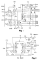
- the figure 1 gives a block diagram of the integrated circuit TSS721 and the figure 2 illustrates an example of using such an integrated circuit as an interface to ensure the format conversion between the computer of a power meter and an M-bus.
- the integrated circuit has a number of input / output connections.
- the BUSL1 and BUSL2 input connections are intended to be connected to the two conductors forming the M-BUS (not shown), the TX output connection is able to be connected to the reception terminal RX-0 of the microprocessor of the meter, preferably via optocouplers allowing galvanic isolation, so as to transmit the data coming from the M-Bus, and the output connection RX is able to be connected to the transmit terminal TX-0 the microprocessor of the meter, always via optocouplers, so as to allow the transmission of data from the meter to the M-Bus.
- the specifications of the TSS721 integrated circuit describe a number of possible arrangements and specific uses of certain output connections.
- the M-Bus standard provides that the M-bus can advantageously be used to power the computer or microprocessor of the energy meter.
- the specification of the integrated circuit TSS721 provides for using the VDD output connection (see figure 1 ) which delivers a regulated voltage at 3.3 volts.
- the RIDD connection is connected to a resistor R38 of 30 KOhms, which corresponds to a configuration of the integrated circuit to a unit of load.
- the integrated circuit is configured for a M-bus current of 1.5 milliamps, and the energy meter can have about 1.2 milliamperes, taking into account the consumption proper to the integrated circuit.
- the available power delivered by the integrated circuit is at most 1.2 x 3.3, or about 4 milli Watts.
- This regulated voltage is insufficient to serve as a power supply for energy meters. Although the average consumption of these is in principle much lower than the available 4 milli Watts, their instantaneous consumption can be greater. On the other hand, to ensure a certain autonomy in case of bus failure, the computer can incorporate significant capacity and super-capacity to be loaded quickly, which requires significant power.
- a first solution consists in configuring the integrated circuit to a number of units of charge greater than 1. Nevertheless, the number of energy meters that can be connected to the same M-bus decreases as the number of load units increases. . Thus, a compromise remains to be made and one seeks to develop energy meters that consume if possible not more than two units of load. However, even with a configuration with two charge units, ie 3 milliamps, the available power is at most equal to 9 milli watts, which remains insufficient for the intended application.
- the power that can be delivered by the integrated circuit TSS721 / TSS721A is variable depending on the components and especially can be punctually but significantly reduced, especially when the integrated circuit is requested for its communication functions with the M-bus.
- the purpose of the present invention is to propose a solution allowing, in the context of an M-bus energy meter whose power supply is supplied by the M-bus, to use a maximum of available power, and thus to guarantee that the computer of the energy meter powered by the M-bus, via an integrated circuit of the component type TSS721 / TSS721A, is made operational as quickly as possible. possible.
- the subject of the present invention is an energy meter, in particular a heat energy meter, capable of exchanging data remotely via an M-Bus link, the energy meter comprising a computer module capable of being powered by the M-Bus link, and an integrated circuit capable, on the one hand, of serving as a communication interface between the computer module and the M-Bus link, and, on the other hand, to deliver on an output connection, a DC voltage signal for the power supply of the computer module, characterized in that the energy meter furthermore comprises a power supply module comprising a DC-DC converter which is galvanically isolated and whose The input is connected to said output connection and whose duty cycle is regulated by the DC voltage signal.
- the integrated circuit is for example of the TSS721 / TSSS721A type, the output connection then being constituted by the STC connection of the integrated circuit delivering a DC voltage signal V STC .
- the DC-DC converter preferably comprises a galvanically isolated transformer, a control module comprising a switch means and an oscillator controlling the opening and closing of the switching means according to said duty cycle, and an operational amplifier amplifying the difference between the value. a DC voltage signal and a reference voltage, and whose output delivers a setpoint for the regulation of the duty cycle to the control module so as to adapt the called current as a function of the value of the DC voltage signal.
- the energy meter also advantageously comprises a backup module replacing the power supply module to overcome situations in which the presence of the M-bus is not detected.
- FIG 3 the relation between an integrated circuit 1 of the TSS721 A type and the computer module 2 of a thermal energy meter in accordance with the invention is shown schematically.
- the connections TXI and RX of the integrated circuit 1 are connected classically respectively to the connections RX-0 and TX-0 of the computer module 2 via isolated optocouplers 3 galvanically.
- the energy meter further comprises, in accordance with the invention, a power supply module comprising a DC-DC converter 4 galvanically isolated, whose input is connected to an output connection of the integrated circuit 1 delivering a DC voltage signal, and whose duty cycle is regulated by the DC voltage signal, as will be explained later in more detail.
- a backup module 5, consisting of super storage capacitors, may also advantageously be used to constitute a reserve of energy replacing the power supply module 4 in the case of defection of the bus for limited periods. In this case, a 3 Volt power supply is provided by this backup module instead of the power supply. provided by the DC-DC converter.
- a supervision module 6 makes it possible to supply the computer with either the output voltage of the DC-DC converter (M-bus present) or the output voltage at 3 Volts of the backup module 5 (M-Bus absent), and thus guarantees the correct operation of the computer 2 for a limited time even in case of interruption of the M-bus.
- the energy available at the output of the integrated circuit 1 is split between the output current I STC_use on the connection STC and the current I VDD on the connection VDD.
- This current I VDD is used during communications for powering the optocouplers of the figure 3 .
- the STC connection delivering a DC voltage of 6.5 volts instead of the VDD connection. recommended by the specifications of the integrated circuit.
- This characteristic combined with the regulation of the duty cycle of the DC-DC converter 4 as a function of the voltage delivered on the output STC makes it possible to obtain a usable power at the output of the integrated circuit very close to the maximum power that the integrated circuit can provide. .
- the current I STC-use will decrease and the voltage V STC will pass below the threshold value V ref .
- the DC-DC converter will then adapt by reducing its duty cycle, typically by reducing the closing time of the transformer primary control switches, so as to call less current.
- the duty cycle of the DC-DC converter will increase, typically by increasing the closing time of the control switches, making it possible to call more current.
- the invention thus takes advantage of the fact that, since the TSS721A circuit itself is already a limited current source, it is possible to use the voltage drop following the use of the maximum current available to regulate the converter.
- the current used is always the maximum that is available: if the available current is reduced, as during a communication with the M-bus, the control reduces the current called.
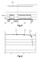
- the figure 5 illustrates an example of variations of the signals during the reception of a communication by the computer module 2. More precisely, the curve referenced RX-0 illustrates the signal received on the reception connection RX-0 of the computer module 2, the referenced curve V STC illustrates the corresponding variations of the DC voltage on the output connection STC, and the curve S reg represents the corresponding variations of the output voltage the operational amplifier acting on the control oscillator switches associated with the primary of the transformer, and therefore on the duty cycle of the converter. It can be seen from these curves that, during a communication on the M-bus, the voltage VSTC decreases and the servo voltage increases so as to decrease the duty cycle, and consequently, the current consumed.
- FIG. 6 illustrates an example of a real characteristic of a TSS721 integrated circuit configured with two load units, with the current values I drawn on the STC connection as abscissa, and the voltage values V STC as ordinate.
- the point referenced P max corresponds to the maximum power that can be delivered by the integrated circuit on the STC output connection, ie 13.6 milliwatts in this example.
- This figure also shows the powers actually delivered by the STC connection in different cases.
- the point referenced A 1 corresponds to the power actually delivered to the STC connection in the absence of any regulation, ie 6 milliwatts in this example.
- the point referenced A 2 corresponds to the power effectively delivered on the STC connection by performing a conventional regulation based on the use of a shunt resistor (current regulation), ie 9.7 milliwatts in this example. Again, a margin must be taken in order to take into account the current that can be pulled on the VDD pin which cuts off the current available on the STC connection.
- This control mode however allows to overcome the tolerances of the transformer but not the TSS721. The operating point must be dimensioned for the worst case of the latter and therefore still far from the optimum.
- the point referenced A 3 corresponds to the power actually delivered to the STC connection by performing voltage regulation in accordance with the invention, ie 13.3 milliwatts in this example, which is very close to the maximum P max .
- This last control mode uses the maximum current available on the STC connection independently of the current drawn on the VDD pin. In addition, it eliminates the tolerance of the transformer and also that of the TSS721 and thus ensures an operating point very close to optimal.
Landscapes
- Physics & Mathematics (AREA)
- General Physics & Mathematics (AREA)
- Dc-Dc Converters (AREA)
- Measuring Volume Flow (AREA)
- Measurement Of Distances Traversed On The Ground (AREA)
- Arrangements For Transmission Of Measured Signals (AREA)
Abstract
Description
- La présente invention concerne le domaine des compteurs d'énergie, notamment des compteurs d'énergie thermique, et plus particulièrement les compteurs d'énergie capables d'échanger des données séries avec un dispositif maître par l'intermédiaire d'un bus M-bus.
- Le M-bus (mis pour la terminologie anglo-saxonne « Meter Bus ») est une norme européenne relativement récente permettant la lecture à distance de compteurs d'énergie, notamment de type électrique ou thermique.
- Pour permettre l'échange des données séries via le bus M-bus, de tels compteurs d'énergie disposent d'une interface de communication avec le M-bus, cette interface étant aujourd'hui sous la forme d'un composant intégré commercialisé par Texas Instrument sous la référence TSS721 ou TSS721A.
- La
figure 1 donne un schéma fonctionnel du circuit intégré TSS721 et lafigure 2 illustre un exemple d'utilisation d'un tel circuit intégré comme interface pour assurer la conversion de format entre le calculateur d'un compteur d'énergie et un M-bus. Le circuit intégré est doté d'un certain nombre de connexions d'entrée/sortie. Parmi celles-ci, les connexions d'entrée BUSL1 et BUSL2 sont destinées à être reliées aux deux conducteurs formant le M-BUS (non représenté), la connexion de sortie TX est apte à être reliée à la borne de réception RX-0 du microprocesseur du compteur, de préférence par l'intermédiaire d'optocoupleurs permettant une isolation galvanique, de façon à transmettre les données provenant du M-Bus, et la connexion de sortie RX est apte à être reliée à la borne d'émission TX-0 du microprocesseur du compteur, toujours par l'intermédiaire d'optocoupleurs, de façon à permettre la transmission des données depuis le compteur vers le M-Bus. - Les spécifications du circuit intégré TSS721 décrivent un certain nombre de montages possibles et d'utilisations spécifiques de certaines connexions de sortie. En particulier, la norme M-Bus prévoit que le M-bus peut avantageusement être utilisé pour alimenter en puissance le calculateur ou microprocesseur du compteur d'énergie. Pour ce faire, la spécification du circuit intégré TSS721 prévoit d'utiliser la connexion de sortie VDD (voir
figure 1 ) qui délivre une tension régulée à 3,3 Volts. - Dans l'exemple représenté sur la
figure 2 , la connexion RIDD est reliée à une résistance R38 de 30 KOhms, ce qui correspond à une configuration du circuit intégré à une unité de charge. Ainsi, le circuit intégré est configuré pour un courant de M-bus de 1,5 milli Ampères, et le compteur d'énergie peut disposer d'environ 1,2 milli Ampères, compte tenu de la consommation propre au circuit intégré. En conséquence, la puissance disponible délivrée par le circuit intégré est au maximum de 1,2 x 3,3, soit environ 4 milli Watts. - Cette tension régulée s'avère bien insuffisante pour servir d'alimentation pour des compteurs d'énergie. Même si la consommation moyenne de ces derniers est en principe très inférieure aux 4 milli Watts disponibles, leur consommation instantanée peut être supérieure. D'autre part, pour assurer une certaine autonomie en cas de coupure du BUS, le calculateur peut intégrer d'importantes capacités et super-capacités devant être chargées rapidement, ce qui nécessite une puissance importante.
- Une première solution consiste à configurer le circuit intégré à un nombre d'unités de charge supérieur à 1. Néanmoins, le nombre de compteurs d'énergie susceptibles d'être connectés au même M-bus diminue lorsque le nombre d'unités de charge augmente. Ainsi, un compromis reste à faire et l'on recherche à développer des compteurs d'énergie qui ne consomment si possible pas plus de deux unités de charge. Cependant, même avec une configuration à deux unités de charge, soit 3 milli Ampères, la puissance disponible est tout au plus égale à 9 milli Watts, ce qui reste insuffisant pour l'application visée.
- En outre, la puissance susceptible d'être délivrée par le circuit intégré TSS721/TSS721A est variable selon les composants et surtout peut être ponctuellement mais significativement réduite, notamment quand le circuit intégré est sollicité pour ses fonctions de communication avec le M-bus.
- La présente invention a pour but de proposer une solution permettant, dans le cadre d'un compteur d'énergie à fonctionnalité M-bus dont l'alimentation en puissance est fournie par le M-bus, d'utiliser un maximum de puissance disponible, et de garantir ainsi que le calculateur du compteur d'énergie alimenté par le M-bus, par l'intermédiaire d'un circuit intégré du type composant TSS721/TSS721A, soit rendu opérationnel le plus rapidement possible.
- Pour ce faire, la présente invention a pour objet un compteur d'énergie, en particulier compteur d'énergie thermique, apte à échanger des données à distance par l'intermédiaire d'une liaison M-Bus, le compteur d'énergie comprenant un module calculateur susceptible d'être alimenté en puissance par la liaison M-Bus, et un circuit intégré apte d'une part, à servir d'interface de communication entre le module calculateur et la liaison M-Bus, et d'autre part, à délivrer sur une connexion de sortie, un signal de tension continue pour l'alimentation du module calculateur, caractérisé en ce que le compteur d'énergie comporte en outre un module d'alimentation en puissance comprenant un convertisseur DC-DC isolé galvaniquement dont l'entrée est connectée à ladite connexion de sortie et dont le rapport cyclique est régulé par le signal de tension continue.
- Le circuit intégré est par exemple du type TSS721/TSSS721A, la connexion de sortie étant alors constituée par la connexion STC du circuit intégré délivrant un signal de tension continue VSTC.
- Le convertisseur DC-DC comporte de préférence un transformateur isolé galvaniquement, un module de commande comportant un moyen interrupteur et un oscillateur commandant l'ouverture et la fermeture du moyen interrupteur selon ledit rapport cyclique, et un amplificateur opérationnel amplifiant l'écart entre la valeur du signal de tension continue et une tension de référence, et dont la sortie délivre une consigne pour la régulation du rapport cyclique au module de commande de manière à adapter le courant appelé en fonction de la valeur du signal de tension continue.
- Le compteur d'énergie comporte en outre avantageusement un module de secours se substituant au module d'alimentation en puissance pour pallier les situations dans lesquelles la présence du M-bus n'est pas détectée.
- L'invention et les avantages qu'elle procure seront mieux compris au vu de la description suivante, faite en référence aux figures annexées, dans lesquelles :
- la
figure 1 , précédemment mentionnée, illustre un schéma fonctionnel du circuit intégré TSS721/TSS721A commercialisé par Texas Instrument ; - la
figure 2 , précédemment décrite, illustre un exemple d'utilisation du circuit intégré précédent comme interface pour assurer la conversion de format entre le calculateur d'un compteur d'énergie et un M-bus, pour une configuration à une unité de charge ; - La
figure 3 illustre, sous forme de synoptique simplifié, certains aspects de la liaison entre le circuit intégré précédent et le calculateur d'un compteur d'énergie, conformes à la présente invention ; - La
figure 4 illustre schématiquement le principe de l'alimentation conforme à la mise en oeuvre préférée de l'invention. - la
figure 5 donne un exemple de régulation selon le principe de l'invention lors d'une communication entre le compteur et le M-bus ; - la
figure 6 est un diagramme permettant de comparer les performances obtenues par l'invention par rapport à d'autres solutions. - Sur la
figure 3 , on a représenté sous forme schématique la relation entre un circuit intégré 1 de type TSS721 A et le module calculateur 2 d'un compteur d'énergie thermique conforme à l'invention. Pour la fonction de communication avec le M-Bus (non représenté), les connexions TXI et RX du circuit intégré 1 sont reliées classiquement respectivement aux connexions RX-0 et TX-0 du module calculateur 2 par l'intermédiaire d'optocoupleurs 3 isolés galvaniquement. - Pour ce qui concerne la fonction d'alimentation en puissance en utilisant l'énergie du M-Bus, le compteur d'énergie comporte en outre, conformément à l'invention, un module d'alimentation en puissance comprenant un convertisseur DC-DC 4 isolé galvaniquement, dont l'entrée est connectée à une connexion de sortie du circuit intégré 1 délivrant un signal de tension continue, et dont le rapport cyclique est régulé par le signal de tension continue , comme cela sera expliqué ultérieurement plus en détail. Un module de secours 5, constitué de super condensateurs de stockage, peut en outre avantageusement être utilisé pour constituer une réserve d'énergie se substituant au module d'alimentation 4 dans le cas de défection du Bus sur des durées limitées. Dans ce cas, une alimentation en puissance à 3 Volts est fournie par ce module de secours à la place de l'alimentation en puissance fournie par le convertisseur DC-DC. Un module de supervision 6 permet de fournir au calculateur soit la tension de sortie du convertisseur DC-DC (M-bus présent), soit la tension de sortie à 3 Volts du module de secours 5 (M-Bus absent), et garantit ainsi le fonctionnement correct du calculateur 2 sur une durée limitée même en cas de coupure du M-bus.
- Une mise en oeuvre préférée de l'invention et le détail de la régulation vont à présent être explicités en référence aux
figures 4 et5 . - Au préalable, si l'on se réfère à nouveau au schéma fonctionnel de la
figure 1 , on note que l'énergie disponible en sortie du circuit intégré 1 est fractionnée entre le courant de sortie ISTC_use sur la connexion STC, et le courant IVDD sur la connexion VDD. Ce courant IVDD est utilisé lors des communications pour l'alimentation des optocoupleurs de lafigure 3 . Conformément à la mise en oeuvre préférée de l'invention, on va utiliser comme connexion de sortie du circuit intégré 1 connectée à l'entrée du convertisseur 4, la connexion STC délivrant une tension continue de 6,5 Volts au lieu de la connexion VDD préconisée par les spécifications du circuit intégré. Cette caractéristique, combinée à la régulation du rapport cyclique du convertisseur DC-DC 4 en fonction de la tension délivrée sur la sortie STC permet d'obtenir une puissance utilisable en sortie du circuit intégrée très proche du maximum de puissance que peut fournir le circuit intégré. - La régulation du rapport cyclique du convertisseur DC-DC en fonction de la tension délivrée sur la connexion STC va à présent être explicitée en référence aux
figures 4 et5 : - Sur la
figure 4 , on a représenté sous forme de synoptique fonctionnel les composantes principales du convertisseur DC-DC 4 selon l'invention. Ce convertisseur DC-DC utilise classiquement un transformateur illustré par son enroulement primaire 40 et son enroulement secondaire 41. L'utilisation du transformateur garantit l'isolation galvanique nécessaire à l'application. Le convertisseur 4 dispose également classiquement en amont de l'enroulement primaire 40, d'un module de commande 42 comportant un moyen interrupteur, typiquement un transistor, et un oscillateur commandant l'ouverture et la fermeture du transistor selon un rapport cyclique donné. Conformément à l'invention, le convertisseur 4 comporte en outre des moyens 43 permettant de réguler le rapport cyclique en fonction de la tension continue présente sur la sortie STC. Ces moyens 43 sont réalisés ici par un amplificateur opérationnel qui amplifie l'écart entre la valeur de la tension de sortie et une tension de référence Vref, et dont la sortie Sreg délivre en conséquence une consigne pour la régulation du rapport cyclique au module de commande 42. Ainsi, on surveille en permanence la tension disponible sur la connexion STC, et on adapte le courant appelé par l'alimentation en modulant le temps d'ouverture du transistor en fonction de cette tension disponible. - Lors des rares appels de courant sur la connexion VDD, le courant ISTC-use va diminuer et la tension VSTC va passer en deçà de la valeur seuil Vref. Le convertisseur DC-DC va alors s'adapter en réduisant son rapport cyclique, typiquement en réduisant le temps de fermeture des interrupteurs de commande du primaire du transformateur, de façon à appeler moins de courant. A l'inverse, lorsque la tension VSTC repasse au-dessus du seuil Vref, le rapport cyclique du convertisseur DC-DC va augmenter, typiquement en augmentant le temps de fermeture des interrupteurs de commande, permettant d'appeler plus de courant.
- L'invention tire ainsi partie du fait que, le circuit TSS721A étant déjà lui- même une source à courant limité, il est possible d'utiliser la chute de tension consécutive à l'utilisation du courant maximum disponible pour réguler le convertisseur. Ainsi, le courant utilisé est toujours le maximum qui soit disponible : si le courant disponible se réduit, comme lors d'une communication avec le M-bus, la régulation réduit le courant appelé.
- La
figure 5 illustre un exemple de variations des signaux lors de la réception d'une communication par le module calculateur 2. Plus précisément, la courbe référencée RX-0 illustre le signal reçu sur la connexion de réception RX-0 du module calculateur 2, la courbe référencée VSTC illustre les variations correspondantes de la tension continue sur la connexion de sortie STC, et la courbe Sreg représente les variations correspondantes de la tension de sortie de l'amplificateur opérationnel agissant sur l'oscillateur de commande des interrupteurs associés au primaire du transformateur, et par conséquent sur le rapport cyclique du convertisseur. On constate sur ces courbes que, lors d'une communication sur le M-bus, la tension VSTC diminue et la tension d'asservissement augmente de manière à faire diminuer le rapport cyclique, et par voie de conséquence, le courant consommé. - L'intérêt de l'invention est visible sur la
figure 6 qui illustre un exemple de caractéristique réelle d'un circuit intégré TSS721 configuré à deux unités de charge, avec en abscisse les valeurs de courant I tiré sur la connexion STC, et en ordonnée les valeurs de tension VSTC. Le point référencé Pmax correspond à la puissance maximale susceptible d'être délivrée par le circuit intégré sur la connexion de sortie STC, soit 13,6 milliwatts dans cet exemple. On a porté en outre sur cette figure les puissances effectivement délivrées par la connexion STC dans différents cas de figures. Ainsi, le point référencé A1 correspond à la puissance délivrée effectivement sur la connexion STC en l'absence de toute régulation, soit 6 milliwatts dans cet exemple. En effet, une marge doit être prise de manière à tenir compte du courant susceptible d'être tiré sur la broche VDD qui se retranche du courant disponible sur la connexion STC. De plus, les tolérances importantes existant sur les composants (TSS721 et transformateur pour les plus significatifs) imposent un point de fonctionnement typique très éloigné de l'optimum. En fonction des tolérances précitées, le point de fonctionnement réel pourra se rapprocher de l'optimum mais aussi s'en éloigner. - Le point référencé A2 correspond à la puissance délivrée effectivement sur la connexion STC en effectuant une régulation classique basée sur l'utilisation d'une résistance de shunt (régulation en courant), soit 9,7 milliwatts dans cet exemple. Là aussi, une marge doit être prise de manière à tenir compte du courant susceptible d'être tiré sur la broche VDD qui se retranche du courant disponible sur la connexion STC. Ce mode de régulation permet toutefois de s'affranchir des tolérances du transformateur mais pas du TSS721. Le point de fonctionnement doit être dimensionné pour le pire cas de ce dernier et donc encore loin de l'optimum.
- Enfin, le point référencé A3 correspond à la puissance délivrée effectivement sur la connexion STC en effectuant la régulation en tension conforme à l'invention, soit 13,3 milliwatts dans cet exemple, ce qui est très proche du maximum Pmax. Ce dernier mode de régulation exploite le courant maximum disponible sur la connexion STC indépendamment du courant tiré sur la broche VDD. De plus elle s'affranchit de la tolérance du transformateur et aussi de celle du TSS721 et assure donc un point de fonctionnement très proche de l'optimal.
Claims (4)
- Compteur d'énergie, en particulier compteur d'énergie thermique, apte à échanger des données à distance par l'intermédiaire d'une liaison M-Bus, le compteur d'énergie comprenant un module calculateur (2) susceptible d'être alimenté en puissance par la liaison M-Bus, et un circuit intégré (1) apte d'une part, à servir d'interface de communication entre le module calculateur (2) et la liaison M-Bus, et d'autre part, à délivrer sur une connexion de sortie (10), un signal de tension continue pour l'alimentation du module calculateur (2), caractérisé en ce que le compteur d'énergie comporte en outre un module d'alimentation en puissance (4) comprenant un convertisseur DC-DC isolé galvaniquement dont l'entrée est connectée à ladite connexion de sortie (10) et dont le rapport cyclique est régulé par le signal de tension continue.
- Compteur d'énergie selon la revendication 1, caractérisé en ce que le circuit intégré (1) est du type TSS721/TSSS721A, et en ce que ladite connexion de sortie (10) est constituée par la connexion STC du circuit intégré (1) délivrant un signal de tension continue VSTC.
- Compteur d'énergie selon l'une quelconques des revendications précédentes, caractérisé en ce que ledit convertisseur DC-DC (4) comporte un transformateur (40, 41) isolé galvaniquement, un module de commande (42) comportant un moyen interrupteur et un oscillateur commandant l'ouverture et la fermeture du moyen interrupteur selon ledit rapport cyclique, et un amplificateur opérationnel (43) qui amplifie l'écart entre la valeur du signal de tension continue et une tension de référence (Vref), et dont la sortie (Sreg) délivre une consigne pour la régulation du rapport cyclique au module de commande (42) de manière à adapter le courant appelé en fonction de la valeur du signal de tension continue.
- Compteur d'énergie selon l'une quelconque des revendications précédentes, caractérisé en ce qu'il comporte en outre un module de secours (5) se substituant au module d'alimentation en puissance (4) pour pallier les situations dans lesquelles la présence du M-bus n'est pas détectée.
Priority Applications (6)
| Application Number | Priority Date | Filing Date | Title |
|---|---|---|---|
| EP09305685A EP2275781B8 (fr) | 2009-07-17 | 2009-07-17 | Compteur d'énergie à alimentation par un M-bus |
| ES09305685T ES2375437T3 (es) | 2009-07-17 | 2009-07-17 | Contador de energ�?a de alimentación por m-bus. |
| AT09305685T ATE539321T1 (de) | 2009-07-17 | 2009-07-17 | Energiezähler mit stromversorgung über einen m- bus |
| PT09305685T PT2275781E (pt) | 2009-07-17 | 2009-07-17 | Contador de energia com alimentação por um m-bus |
| PCT/EP2010/059846 WO2011006836A1 (fr) | 2009-07-17 | 2010-07-08 | Compteur d'energie a alimentation par un m-bus |
| CN2010800320635A CN102483334A (zh) | 2009-07-17 | 2010-07-08 | 由m-bus提供电力的能量表 |
Applications Claiming Priority (1)
| Application Number | Priority Date | Filing Date | Title |
|---|---|---|---|
| EP09305685A EP2275781B8 (fr) | 2009-07-17 | 2009-07-17 | Compteur d'énergie à alimentation par un M-bus |
Publications (3)
| Publication Number | Publication Date |
|---|---|
| EP2275781A1 true EP2275781A1 (fr) | 2011-01-19 |
| EP2275781B1 EP2275781B1 (fr) | 2011-12-28 |
| EP2275781B8 EP2275781B8 (fr) | 2012-03-21 |
Family
ID=41381675
Family Applications (1)
| Application Number | Title | Priority Date | Filing Date |
|---|---|---|---|
| EP09305685A Not-in-force EP2275781B8 (fr) | 2009-07-17 | 2009-07-17 | Compteur d'énergie à alimentation par un M-bus |
Country Status (6)
| Country | Link |
|---|---|
| EP (1) | EP2275781B8 (fr) |
| CN (1) | CN102483334A (fr) |
| AT (1) | ATE539321T1 (fr) |
| ES (1) | ES2375437T3 (fr) |
| PT (1) | PT2275781E (fr) |
| WO (1) | WO2011006836A1 (fr) |
Cited By (1)
| Publication number | Priority date | Publication date | Assignee | Title |
|---|---|---|---|---|
| CN103728951A (zh) * | 2014-01-06 | 2014-04-16 | 深圳市兴源智能仪表科技有限公司 | 一种仪表总线从设备接口的恒流二极管电路 |
Families Citing this family (6)
| Publication number | Priority date | Publication date | Assignee | Title |
|---|---|---|---|---|
| CN102298345B (zh) * | 2011-05-20 | 2013-06-19 | 深圳市骏普科技开发有限公司 | 一种m-bus总线的通讯方法 |
| CN102769331A (zh) * | 2012-06-25 | 2012-11-07 | 天津市同裕能源科技发展有限公司 | 带m-bus总线供电的智能球阀 |
| CN106781411B (zh) * | 2016-12-22 | 2023-09-08 | 武汉盛帆电子股份有限公司 | M-Bus双主机并网方法及通信接口转换器、M-Bus双主机控制系统 |
| CN106877856B (zh) * | 2016-12-28 | 2021-02-02 | 深圳市展恒电子有限公司 | 用于mbus的从站接口装置 |
| CN110492567B (zh) * | 2019-06-26 | 2021-03-26 | 上海云衡科技有限公司 | 供电系统 |
| CN113296436B (zh) * | 2021-05-07 | 2022-07-15 | 宁波水表(集团)股份有限公司 | 基于mbus总线模拟电路的从站设备 |
Citations (3)
| Publication number | Priority date | Publication date | Assignee | Title |
|---|---|---|---|---|
| EP0961122A1 (fr) * | 1998-05-28 | 1999-12-01 | Electrowatt Technology Innovation AG | Compteur d'électricité avec un compteur de base comprenant un microprocesseur, qui est équipé d'un ou plusieurs modules interchangeables |
| EP0986039A1 (fr) * | 1998-09-07 | 2000-03-15 | Endress + Hauser GmbH + Co. | Dispositif pour l'alimentation d'un émetteur d'une boucle de courant |
| EP2045791A1 (fr) * | 2007-10-01 | 2009-04-08 | Siemens Milltronics Process Instruments Inc. | Dispositif électronique |
Family Cites Families (1)
| Publication number | Priority date | Publication date | Assignee | Title |
|---|---|---|---|---|
| CN2752869Y (zh) * | 2004-07-23 | 2006-01-18 | 杭州利尔达单片机技术有限公司 | 流体表的网络直流载波通讯从站接口电路 |
-
2009
- 2009-07-17 PT PT09305685T patent/PT2275781E/pt unknown
- 2009-07-17 ES ES09305685T patent/ES2375437T3/es active Active
- 2009-07-17 AT AT09305685T patent/ATE539321T1/de active
- 2009-07-17 EP EP09305685A patent/EP2275781B8/fr not_active Not-in-force
-
2010
- 2010-07-08 WO PCT/EP2010/059846 patent/WO2011006836A1/fr not_active Ceased
- 2010-07-08 CN CN2010800320635A patent/CN102483334A/zh active Pending
Patent Citations (3)
| Publication number | Priority date | Publication date | Assignee | Title |
|---|---|---|---|---|
| EP0961122A1 (fr) * | 1998-05-28 | 1999-12-01 | Electrowatt Technology Innovation AG | Compteur d'électricité avec un compteur de base comprenant un microprocesseur, qui est équipé d'un ou plusieurs modules interchangeables |
| EP0986039A1 (fr) * | 1998-09-07 | 2000-03-15 | Endress + Hauser GmbH + Co. | Dispositif pour l'alimentation d'un émetteur d'une boucle de courant |
| EP2045791A1 (fr) * | 2007-10-01 | 2009-04-08 | Siemens Milltronics Process Instruments Inc. | Dispositif électronique |
Cited By (1)
| Publication number | Priority date | Publication date | Assignee | Title |
|---|---|---|---|---|
| CN103728951A (zh) * | 2014-01-06 | 2014-04-16 | 深圳市兴源智能仪表科技有限公司 | 一种仪表总线从设备接口的恒流二极管电路 |
Also Published As
| Publication number | Publication date |
|---|---|
| PT2275781E (pt) | 2012-01-24 |
| EP2275781B8 (fr) | 2012-03-21 |
| ATE539321T1 (de) | 2012-01-15 |
| EP2275781B1 (fr) | 2011-12-28 |
| CN102483334A (zh) | 2012-05-30 |
| ES2375437T3 (es) | 2012-02-29 |
| WO2011006836A1 (fr) | 2011-01-20 |
Similar Documents
| Publication | Publication Date | Title |
|---|---|---|
| EP2275781B1 (fr) | Compteur d'énergie à alimentation par un M-bus | |
| EP2524397B1 (fr) | Système de gestion et de commande de panneaux photovoltaïques | |
| FR2784517A1 (fr) | Circuit d'alimentation en energie pour un reseau de bord de vehicule automobile a deux branches d'alimentation de tensions differentes | |
| EP3404334B2 (fr) | Procede et installation de stockage d'energie utilisant un chauffe-eau | |
| FR2996372A1 (fr) | Systeme de charge sans contact d'une batterie de vehicule automobile | |
| EP3227982A1 (fr) | Procédé pour la gestion d'énergie | |
| EP2073340B1 (fr) | Système d'alimentation électrique pour satellite | |
| EP2861450A2 (fr) | Procédé et système pour la mise en veille et le réveil d'un module de commande de véhicule automobile électrique | |
| EP1825557B1 (fr) | Procede de gestion d'une batterie rechargeable et batterie rechargeable adaptee pour mettre en oevre ce procede | |
| EP3323668B1 (fr) | Système et procédé de commande d'alimentation électrique sans interruption domestique connectée à un véhicule électrique ou hybride | |
| EP3179597B1 (fr) | Dispositif de fourniture d'electricite monophasee et triphasee ameliore | |
| FR3033674A1 (fr) | Carte electronique de pilotage energetique d'un equipement electrique autonome et communicant | |
| EP2438687B1 (fr) | Adaptateur courant porteur intégré | |
| EP2595279B1 (fr) | Dispositif d'alimentation à découpage et aéronef comprenant au moins un tel dispositif | |
| FR2859856A1 (fr) | Systeme et disposiif d'alimentation a distance d'un equipement de traitement d'informations | |
| FR2933820A1 (fr) | Procede et dispositif de commande de consommateurs electriques. | |
| FR2779024A1 (fr) | Installation de chauffage a convecteurs electriques | |
| EP1880460A2 (fr) | Circuit d'alimentation sans interruption | |
| EP3258569A1 (fr) | Système d'alimentation comprenant une unité de gestion principale et une unité de gestion de réserve | |
| FR3114056A1 (fr) | Véhicule électrique et dispositif de commutation pour un réseau électrique domestique | |
| EP1177613A1 (fr) | Systeme d'alimentation a partir d'une ligne telephonique | |
| FR3164663A1 (fr) | Borne de recharge économe en énergie | |
| FR2955210A1 (fr) | Systeme de gestion et de commande de panneaux photovoltaiques | |
| WO2023180149A1 (fr) | Dispositif electronique comprenant une source d'alimentation interne | |
| FR2875651A1 (fr) | Convertisseur de tension dc/dc a consigne de courant limitee |
Legal Events
| Date | Code | Title | Description |
|---|---|---|---|
| PUAI | Public reference made under article 153(3) epc to a published international application that has entered the european phase |
Free format text: ORIGINAL CODE: 0009012 |
|
| AK | Designated contracting states |
Kind code of ref document: A1 Designated state(s): AT BE BG CH CY CZ DE DK EE ES FI FR GB GR HR HU IE IS IT LI LT LU LV MC MK MT NL NO PL PT RO SE SI SK SM TR |
|
| AX | Request for extension of the european patent |
Extension state: AL BA RS |
|
| 17P | Request for examination filed |
Effective date: 20110719 |
|
| RIC1 | Information provided on ipc code assigned before grant |
Ipc: G08C 19/02 20060101ALI20110815BHEP Ipc: G01D 4/02 20060101AFI20110815BHEP |
|
| GRAP | Despatch of communication of intention to grant a patent |
Free format text: ORIGINAL CODE: EPIDOSNIGR1 |
|
| GRAS | Grant fee paid |
Free format text: ORIGINAL CODE: EPIDOSNIGR3 |
|
| GRAA | (expected) grant |
Free format text: ORIGINAL CODE: 0009210 |
|
| AK | Designated contracting states |
Kind code of ref document: B1 Designated state(s): AT BE BG CH CY CZ DE DK EE ES FI FR GB GR HR HU IE IS IT LI LT LU LV MC MK MT NL NO PL PT RO SE SI SK SM TR |
|
| REG | Reference to a national code |
Ref country code: GB Ref legal event code: FG4D Free format text: NOT ENGLISH |
|
| REG | Reference to a national code |
Ref country code: CH Ref legal event code: EP |
|
| REG | Reference to a national code |
Ref country code: AT Ref legal event code: REF Ref document number: 539321 Country of ref document: AT Kind code of ref document: T Effective date: 20120115 |
|
| REG | Reference to a national code |
Ref country code: IE Ref legal event code: FG4D |
|
| REG | Reference to a national code |
Ref country code: PT Ref legal event code: SC4A Free format text: AVAILABILITY OF NATIONAL TRANSLATION Effective date: 20120116 |
|
| RAP2 | Party data changed (patent owner data changed or rights of a patent transferred) |
Owner name: ITRON FRANCE |
|
| REG | Reference to a national code |
Ref country code: NL Ref legal event code: T3 |
|
| REG | Reference to a national code |
Ref country code: ES Ref legal event code: FG2A Ref document number: 2375437 Country of ref document: ES Kind code of ref document: T3 Effective date: 20120229 |
|
| REG | Reference to a national code |
Ref country code: DE Ref legal event code: R096 Ref document number: 602009004377 Country of ref document: DE Effective date: 20120315 |
|
| PG25 | Lapsed in a contracting state [announced via postgrant information from national office to epo] |
Ref country code: LT Free format text: LAPSE BECAUSE OF FAILURE TO SUBMIT A TRANSLATION OF THE DESCRIPTION OR TO PAY THE FEE WITHIN THE PRESCRIBED TIME-LIMIT Effective date: 20111228 Ref country code: NO Free format text: LAPSE BECAUSE OF FAILURE TO SUBMIT A TRANSLATION OF THE DESCRIPTION OR TO PAY THE FEE WITHIN THE PRESCRIBED TIME-LIMIT Effective date: 20120328 |
|
| LTIE | Lt: invalidation of european patent or patent extension |
Effective date: 20111228 |
|
| PG25 | Lapsed in a contracting state [announced via postgrant information from national office to epo] |
Ref country code: SI Free format text: LAPSE BECAUSE OF FAILURE TO SUBMIT A TRANSLATION OF THE DESCRIPTION OR TO PAY THE FEE WITHIN THE PRESCRIBED TIME-LIMIT Effective date: 20111228 Ref country code: GR Free format text: LAPSE BECAUSE OF FAILURE TO SUBMIT A TRANSLATION OF THE DESCRIPTION OR TO PAY THE FEE WITHIN THE PRESCRIBED TIME-LIMIT Effective date: 20120329 Ref country code: SE Free format text: LAPSE BECAUSE OF FAILURE TO SUBMIT A TRANSLATION OF THE DESCRIPTION OR TO PAY THE FEE WITHIN THE PRESCRIBED TIME-LIMIT Effective date: 20111228 Ref country code: LV Free format text: LAPSE BECAUSE OF FAILURE TO SUBMIT A TRANSLATION OF THE DESCRIPTION OR TO PAY THE FEE WITHIN THE PRESCRIBED TIME-LIMIT Effective date: 20111228 Ref country code: HR Free format text: LAPSE BECAUSE OF FAILURE TO SUBMIT A TRANSLATION OF THE DESCRIPTION OR TO PAY THE FEE WITHIN THE PRESCRIBED TIME-LIMIT Effective date: 20111228 |
|
| PG25 | Lapsed in a contracting state [announced via postgrant information from national office to epo] |
Ref country code: CY Free format text: LAPSE BECAUSE OF FAILURE TO SUBMIT A TRANSLATION OF THE DESCRIPTION OR TO PAY THE FEE WITHIN THE PRESCRIBED TIME-LIMIT Effective date: 20111228 |
|
| REG | Reference to a national code |
Ref country code: IE Ref legal event code: FD4D |
|
| PG25 | Lapsed in a contracting state [announced via postgrant information from national office to epo] |
Ref country code: IS Free format text: LAPSE BECAUSE OF FAILURE TO SUBMIT A TRANSLATION OF THE DESCRIPTION OR TO PAY THE FEE WITHIN THE PRESCRIBED TIME-LIMIT Effective date: 20120428 Ref country code: IE Free format text: LAPSE BECAUSE OF FAILURE TO SUBMIT A TRANSLATION OF THE DESCRIPTION OR TO PAY THE FEE WITHIN THE PRESCRIBED TIME-LIMIT Effective date: 20111228 Ref country code: SK Free format text: LAPSE BECAUSE OF FAILURE TO SUBMIT A TRANSLATION OF THE DESCRIPTION OR TO PAY THE FEE WITHIN THE PRESCRIBED TIME-LIMIT Effective date: 20111228 Ref country code: BG Free format text: LAPSE BECAUSE OF FAILURE TO SUBMIT A TRANSLATION OF THE DESCRIPTION OR TO PAY THE FEE WITHIN THE PRESCRIBED TIME-LIMIT Effective date: 20120328 Ref country code: CZ Free format text: LAPSE BECAUSE OF FAILURE TO SUBMIT A TRANSLATION OF THE DESCRIPTION OR TO PAY THE FEE WITHIN THE PRESCRIBED TIME-LIMIT Effective date: 20111228 Ref country code: EE Free format text: LAPSE BECAUSE OF FAILURE TO SUBMIT A TRANSLATION OF THE DESCRIPTION OR TO PAY THE FEE WITHIN THE PRESCRIBED TIME-LIMIT Effective date: 20111228 |
|
| PG25 | Lapsed in a contracting state [announced via postgrant information from national office to epo] |
Ref country code: RO Free format text: LAPSE BECAUSE OF FAILURE TO SUBMIT A TRANSLATION OF THE DESCRIPTION OR TO PAY THE FEE WITHIN THE PRESCRIBED TIME-LIMIT Effective date: 20111228 Ref country code: PL Free format text: LAPSE BECAUSE OF FAILURE TO SUBMIT A TRANSLATION OF THE DESCRIPTION OR TO PAY THE FEE WITHIN THE PRESCRIBED TIME-LIMIT Effective date: 20111228 |
|
| PLBI | Opposition filed |
Free format text: ORIGINAL CODE: 0009260 |
|
| PG25 | Lapsed in a contracting state [announced via postgrant information from national office to epo] |
Ref country code: DK Free format text: LAPSE BECAUSE OF FAILURE TO SUBMIT A TRANSLATION OF THE DESCRIPTION OR TO PAY THE FEE WITHIN THE PRESCRIBED TIME-LIMIT Effective date: 20111228 |
|
| PLAX | Notice of opposition and request to file observation + time limit sent |
Free format text: ORIGINAL CODE: EPIDOSNOBS2 |
|
| 26 | Opposition filed |
Opponent name: SONTEX S.A. Effective date: 20120928 |
|
| REG | Reference to a national code |
Ref country code: DE Ref legal event code: R026 Ref document number: 602009004377 Country of ref document: DE Effective date: 20120928 |
|
| PLBP | Opposition withdrawn |
Free format text: ORIGINAL CODE: 0009264 |
|
| BERE | Be: lapsed |
Owner name: ITRON FRANCE Effective date: 20120731 |
|
| REG | Reference to a national code |
Ref country code: NL Ref legal event code: V1 Effective date: 20130201 |
|
| PG25 | Lapsed in a contracting state [announced via postgrant information from national office to epo] |
Ref country code: MC Free format text: LAPSE BECAUSE OF NON-PAYMENT OF DUE FEES Effective date: 20120731 Ref country code: MK Free format text: LAPSE BECAUSE OF FAILURE TO SUBMIT A TRANSLATION OF THE DESCRIPTION OR TO PAY THE FEE WITHIN THE PRESCRIBED TIME-LIMIT Effective date: 20111228 |
|
| PLBB | Reply of patent proprietor to notice(s) of opposition received |
Free format text: ORIGINAL CODE: EPIDOSNOBS3 |
|
| REG | Reference to a national code |
Ref country code: PT Ref legal event code: MM4A Free format text: LAPSE DUE TO NON-PAYMENT OF FEES Effective date: 20130417 |
|
| REG | Reference to a national code |
Ref country code: FR Ref legal event code: ST Effective date: 20130329 |
|
| PG25 | Lapsed in a contracting state [announced via postgrant information from national office to epo] |
Ref country code: FR Free format text: LAPSE BECAUSE OF NON-PAYMENT OF DUE FEES Effective date: 20120731 Ref country code: DE Free format text: LAPSE BECAUSE OF NON-PAYMENT OF DUE FEES Effective date: 20130201 Ref country code: NL Free format text: LAPSE BECAUSE OF NON-PAYMENT OF DUE FEES Effective date: 20130201 |
|
| REG | Reference to a national code |
Ref country code: DE Ref legal event code: R119 Ref document number: 602009004377 Country of ref document: DE Effective date: 20130201 |
|
| PG25 | Lapsed in a contracting state [announced via postgrant information from national office to epo] |
Ref country code: BE Free format text: LAPSE BECAUSE OF NON-PAYMENT OF DUE FEES Effective date: 20120731 |
|
| PG25 | Lapsed in a contracting state [announced via postgrant information from national office to epo] |
Ref country code: FI Free format text: LAPSE BECAUSE OF FAILURE TO SUBMIT A TRANSLATION OF THE DESCRIPTION OR TO PAY THE FEE WITHIN THE PRESCRIBED TIME-LIMIT Effective date: 20111228 |
|
| REG | Reference to a national code |
Ref country code: PT Ref legal event code: NF4A Free format text: RESTITUTIO IN INTEGRUM Effective date: 20130711 |
|
| PG25 | Lapsed in a contracting state [announced via postgrant information from national office to epo] |
Ref country code: MT Free format text: LAPSE BECAUSE OF FAILURE TO SUBMIT A TRANSLATION OF THE DESCRIPTION OR TO PAY THE FEE WITHIN THE PRESCRIBED TIME-LIMIT Effective date: 20111228 |
|
| PG25 | Lapsed in a contracting state [announced via postgrant information from national office to epo] |
Ref country code: PT Free format text: LAPSE BECAUSE OF NON-PAYMENT OF DUE FEES Effective date: 20130417 |
|
| REG | Reference to a national code |
Ref country code: ES Ref legal event code: FD2A Effective date: 20131018 |
|
| PG25 | Lapsed in a contracting state [announced via postgrant information from national office to epo] |
Ref country code: ES Free format text: LAPSE BECAUSE OF NON-PAYMENT OF DUE FEES Effective date: 20120718 |
|
| PGFP | Annual fee paid to national office [announced via postgrant information from national office to epo] |
Ref country code: CH Payment date: 20130729 Year of fee payment: 5 Ref country code: PT Payment date: 20130417 Year of fee payment: 5 |
|
| PGRI | Patent reinstated in contracting state [announced from national office to epo] |
Ref country code: PT Effective date: 20130711 |
|
| PGFP | Annual fee paid to national office [announced via postgrant information from national office to epo] |
Ref country code: IT Payment date: 20130722 Year of fee payment: 5 |
|
| PLBD | Termination of opposition procedure: decision despatched |
Free format text: ORIGINAL CODE: EPIDOSNOPC1 |
|
| GBPC | Gb: european patent ceased through non-payment of renewal fee |
Effective date: 20130717 |
|
| PG25 | Lapsed in a contracting state [announced via postgrant information from national office to epo] |
Ref country code: TR Free format text: LAPSE BECAUSE OF FAILURE TO SUBMIT A TRANSLATION OF THE DESCRIPTION OR TO PAY THE FEE WITHIN THE PRESCRIBED TIME-LIMIT Effective date: 20111228 Ref country code: GB Free format text: LAPSE BECAUSE OF NON-PAYMENT OF DUE FEES Effective date: 20130717 |
|
| PLBM | Termination of opposition procedure: date of legal effect published |
Free format text: ORIGINAL CODE: 0009276 |
|
| STAA | Information on the status of an ep patent application or granted ep patent |
Free format text: STATUS: OPPOSITION PROCEDURE CLOSED |
|
| PG25 | Lapsed in a contracting state [announced via postgrant information from national office to epo] |
Ref country code: LU Free format text: LAPSE BECAUSE OF NON-PAYMENT OF DUE FEES Effective date: 20120717 Ref country code: SM Free format text: LAPSE BECAUSE OF FAILURE TO SUBMIT A TRANSLATION OF THE DESCRIPTION OR TO PAY THE FEE WITHIN THE PRESCRIBED TIME-LIMIT Effective date: 20111228 |
|
| 27C | Opposition proceedings terminated |
Effective date: 20140221 |
|
| PG25 | Lapsed in a contracting state [announced via postgrant information from national office to epo] |
Ref country code: HU Free format text: LAPSE BECAUSE OF FAILURE TO SUBMIT A TRANSLATION OF THE DESCRIPTION OR TO PAY THE FEE WITHIN THE PRESCRIBED TIME-LIMIT Effective date: 20090717 |
|
| REG | Reference to a national code |
Ref country code: PT Ref legal event code: MM4A Free format text: LAPSE DUE TO NON-PAYMENT OF FEES Effective date: 20150119 |
|
| REG | Reference to a national code |
Ref country code: CH Ref legal event code: PL |
|
| PG25 | Lapsed in a contracting state [announced via postgrant information from national office to epo] |
Ref country code: PT Free format text: LAPSE BECAUSE OF NON-PAYMENT OF DUE FEES Effective date: 20150119 Ref country code: IT Free format text: LAPSE BECAUSE OF NON-PAYMENT OF DUE FEES Effective date: 20140717 Ref country code: CH Free format text: LAPSE BECAUSE OF NON-PAYMENT OF DUE FEES Effective date: 20140731 Ref country code: LI Free format text: LAPSE BECAUSE OF NON-PAYMENT OF DUE FEES Effective date: 20140731 |
|
| REG | Reference to a national code |
Ref country code: AT Ref legal event code: MM01 Ref document number: 539321 Country of ref document: AT Kind code of ref document: T Effective date: 20140717 |
|
| PG25 | Lapsed in a contracting state [announced via postgrant information from national office to epo] |
Ref country code: AT Free format text: LAPSE BECAUSE OF NON-PAYMENT OF DUE FEES Effective date: 20140717 |