EP2275655A2 - A flow discharge device - Google Patents
A flow discharge device Download PDFInfo
- Publication number
- EP2275655A2 EP2275655A2 EP20100167136 EP10167136A EP2275655A2 EP 2275655 A2 EP2275655 A2 EP 2275655A2 EP 20100167136 EP20100167136 EP 20100167136 EP 10167136 A EP10167136 A EP 10167136A EP 2275655 A2 EP2275655 A2 EP 2275655A2
- Authority
- EP
- European Patent Office
- Prior art keywords
- flow
- discharge
- discharge device
- outlet member
- duct
- Prior art date
- Legal status (The legal status is an assumption and is not a legal conclusion. Google has not performed a legal analysis and makes no representation as to the accuracy of the status listed.)
- Withdrawn
Links
Images

Classifications
-
- F—MECHANICAL ENGINEERING; LIGHTING; HEATING; WEAPONS; BLASTING
- F02—COMBUSTION ENGINES; HOT-GAS OR COMBUSTION-PRODUCT ENGINE PLANTS
- F02C—GAS-TURBINE PLANTS; AIR INTAKES FOR JET-PROPULSION PLANTS; CONTROLLING FUEL SUPPLY IN AIR-BREATHING JET-PROPULSION PLANTS
- F02C9/00—Controlling gas-turbine plants; Controlling fuel supply in air- breathing jet-propulsion plants
- F02C9/16—Control of working fluid flow
- F02C9/18—Control of working fluid flow by bleeding, bypassing or acting on variable working fluid interconnections between turbines or compressors or their stages
-
- F—MECHANICAL ENGINEERING; LIGHTING; HEATING; WEAPONS; BLASTING
- F01—MACHINES OR ENGINES IN GENERAL; ENGINE PLANTS IN GENERAL; STEAM ENGINES
- F01D—NON-POSITIVE DISPLACEMENT MACHINES OR ENGINES, e.g. STEAM TURBINES
- F01D17/00—Regulating or controlling by varying flow
- F01D17/10—Final actuators
- F01D17/105—Final actuators by passing part of the fluid
-
- F—MECHANICAL ENGINEERING; LIGHTING; HEATING; WEAPONS; BLASTING
- F05—INDEXING SCHEMES RELATING TO ENGINES OR PUMPS IN VARIOUS SUBCLASSES OF CLASSES F01-F04
- F05D—INDEXING SCHEME FOR ASPECTS RELATING TO NON-POSITIVE-DISPLACEMENT MACHINES OR ENGINES, GAS-TURBINES OR JET-PROPULSION PLANTS
- F05D2250/00—Geometry
- F05D2250/40—Movement of components
- F05D2250/41—Movement of components with one degree of freedom
-
- Y—GENERAL TAGGING OF NEW TECHNOLOGICAL DEVELOPMENTS; GENERAL TAGGING OF CROSS-SECTIONAL TECHNOLOGIES SPANNING OVER SEVERAL SECTIONS OF THE IPC; TECHNICAL SUBJECTS COVERED BY FORMER USPC CROSS-REFERENCE ART COLLECTIONS [XRACs] AND DIGESTS
- Y10—TECHNICAL SUBJECTS COVERED BY FORMER USPC
- Y10T—TECHNICAL SUBJECTS COVERED BY FORMER US CLASSIFICATION
- Y10T137/00—Fluid handling
- Y10T137/2496—Self-proportioning or correlating systems
- Y10T137/2559—Self-controlled branched flow systems
- Y10T137/2564—Plural inflows
- Y10T137/2572—One inflow supplements another
-
- Y—GENERAL TAGGING OF NEW TECHNOLOGICAL DEVELOPMENTS; GENERAL TAGGING OF CROSS-SECTIONAL TECHNOLOGIES SPANNING OVER SEVERAL SECTIONS OF THE IPC; TECHNICAL SUBJECTS COVERED BY FORMER USPC CROSS-REFERENCE ART COLLECTIONS [XRACs] AND DIGESTS
- Y10—TECHNICAL SUBJECTS COVERED BY FORMER USPC
- Y10T—TECHNICAL SUBJECTS COVERED BY FORMER US CLASSIFICATION
- Y10T137/00—Fluid handling
- Y10T137/8593—Systems
- Y10T137/87571—Multiple inlet with single outlet
- Y10T137/87652—With means to promote mixing or combining of plural fluids
-
- Y—GENERAL TAGGING OF NEW TECHNOLOGICAL DEVELOPMENTS; GENERAL TAGGING OF CROSS-SECTIONAL TECHNOLOGIES SPANNING OVER SEVERAL SECTIONS OF THE IPC; TECHNICAL SUBJECTS COVERED BY FORMER USPC CROSS-REFERENCE ART COLLECTIONS [XRACs] AND DIGESTS
- Y10—TECHNICAL SUBJECTS COVERED BY FORMER USPC
- Y10T—TECHNICAL SUBJECTS COVERED BY FORMER US CLASSIFICATION
- Y10T137/00—Fluid handling
- Y10T137/8593—Systems
- Y10T137/87917—Flow path with serial valves and/or closures
- Y10T137/88054—Direct response normally closed valve limits direction of flow
Definitions
- This invention relates to a flow discharge device in a duct, and is particularly, although not exclusively, concerned with such a device for discharging compressor bleed air into a bypass duct of a gas turbine engine.
- a gas turbine engine When a gas turbine engine is operating under transient conditions, for example when decelerating, it may be necessary to bleed air at high pressure from the core gas flow through the engine. Such air may be discharged through a discharge device into a bypass flow within the engine. Bleed valves are provided to control the discharge of air. The flow of bleed air from the core gas flow into the bypass flow takes place over a substantial pressure drop, and can generate significant noise. It is therefore usual for the discharge device to be configured so as to reduce the noise.
- a typical measure is to discharge the bleed air into the bypass duct through a perforated plate, sometimes referred to as a "pepper pot" which is flush with the wall of the bypass duct.
- the pepper pot serves to break the single body of air flowing towards the bypass duct into a large number of smaller jets which promote small-scale turbulence and hence quicker mixing with the main flow through the bypass duct.
- the individual flow jets from the pepper pot holes tend to coalesce into a single plume, and consequently the bleed flow does not mix rapidly with the main flow.
- the plume also blocks the main flow and creates a wake behind it. If the pepper pot is flush with the wall of the bypass duct hot air and high-energy vortices in the wake can flow into contact with the bypass duct surfaces creating "hot spots" where components can be overheated and consequently damaged.
- US 7434405 discloses a bleed diffuser for a gas turbine engine which is extendable so as to project beyond a wall of the gas turbine engine into an air flow, when air is to be discharged from the bleed diffuser. Extension of the bleed diffuser is achieved by means of an actuator such as an electrical motor. Bleed diffusers need to be deployed rapidly, for relatively short periods, and consequently a large and powerful actuator is required. Also, the control of the actuator has to be coordinated with that of the rest of the bleed system, introducing complexity and reliability issues.
- a flow discharge device for discharging flow into a duct, the device comprising a discharge outlet member having at least one discharge aperture, the outlet member being displaceable by the pressure of a secondary fluid in a secondary fluid source from a retracted position in which the discharge aperture is situated outside the duct, to an extended position in which the discharge aperture is situated within the duct, whereby the secondary fluid flow is discharged through the aperture into a main fluid flow travelling along the duct.
- the present invention thus enables the discharge outlet member to be moved automatically into the extended position by the pressure of the secondary fluid, without requiring any additional control systems or actuators.
- the discharge outlet member may be mounted displaceably in a housing which is secured with respect to a wall of the duct.
- the housing may be provided with a bleed valve which, when open, provides communication between the interior of the housing and the secondary fluid source.
- the discharge outlet member may comprise an end wall and a skirt which extends from the end wall and telescopically engages the housing, the aperture being provided in the skirt. In the retracted position of the discharge outlet member, the end wall may lie substantially flush with the duct wall.
- the aperture may be one of an array of apertures which permit the flow of the secondary fluid from the interior of the skirt to the duct when the discharge outlet member is in the extended position.
- the aperture, or at least one of the apertures may be in the form of a slot.
- a silencer element may be disposed in the skirt at a position away from the end wall, the secondary fluid acting on the silencer element to displace the outlet member to the extended position.
- Return means may be provided for returning the discharge outlet member to the retracted position when isolated from the secondary fluid source.
- the return means may be resilient means, for example a spring acting between the silencer element and an abutment which is secured with respect to the housing.
- a damping means may be provided for damping displacement of the discharge outlet member towards the retracted and/or extended positions.
- the present invention also provides a gas turbine engine provided with a flow discharge device as defined above, the duct being a bypass duct of the gas turbine engine, and the discharge device comprising a compressor bleed assembly.
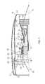
- a ducted fan gas turbine engine generally indicated at 10 has a principal and rotational axis 11.
- the engine 10 comprises, in axial flow series, an air intake 12, a propulsive fan 13, an intermediate pressure compressor 14, a high-pressure compressor 15, combustion equipment 16, a high-pressure turbine 17, an intermediate pressure turbine 18, a low-pressure turbine 19 and a core exhaust nozzle 20.
- a nacelle 21 generally surrounds the engine 10 and defines the intake 12, a bypass duct 22 and an exhaust nozzle 23.
- the gas turbine engine 10 works in the conventional manner so that air entering the intake 12 is accelerated by the fan 13 to produce two air flows: a first airflow A into the intermediate pressure compressor 14 and a second airflow B which passes through the bypass duct 22 to provide propulsive thrust.
- the intermediate pressure compressor 14 compresses the airflow A directed into it before delivering that air to the high pressure compressor 15 where further compression takes place.
- the compressed air exhausted from the high-pressure compressor 15 is directed into the combustion equipment 16 where it is mixed with fuel and the mixture combusted.
- the resultant hot combustion products then expand through, and thereby drive, the high, intermediate and low-pressure turbines 17, 18, 19 before being exhausted through the nozzle 20 to provide additional propulsive thrust.
- the high, intermediate and low-pressure turbines 17, 18, 19 respectively drive the high and intermediate pressure compressors 15, 14 and the fan 13 by suitable interconnecting shafts.
- the fan 13 is circumferentially surrounded by a structural member in the form of a fan casing 24, which is supported by an annular array of outlet guide vanes 28.
- the fan casing 24 comprises a rigid containment casing 25 and attached inwardly thereto is a rear fan casing 26.
- the bypass duct 22 is defined between the rear fan casing 26 and an inner wall 27.
- the inner wall 27 is spaced outwardly from a compressor casing structure 29 which accommodates the intermediate and high pressure compressors 14, 15.
- bleed assemblies 30 are provided to release pressure from an upstream part of a compressor 14, 15. Operation of a bleed assembly 30 and engine operability are described in " The Jet Engine” 6th Edition, 2005, Rolls-Royce plc, pages 79-80 , and details of such operation will therefore only be briefly mentioned herein.
- the bleed assembly 30 comprises a bleed valve 34 which communicates at one end with the respective compressor 14, 15 through the casing structure 29 and is connected at its other end to a housing 36.
- a discharge outlet member 38 discharge outlet member 38 is mounted within the housing 36.
- the housing 36 is supported between the inner wall 27 of the bypass duct 22, and the casing structure 29.
- a fire seal 40 carried by an out-turned flange of the housing 36, contacts the radially inner surface of the inner wall 27, at a recess 42 surrounding the opening 33.
- the housing 36 is of cylindrical form, but narrows to a reduced diameter at its radially inner end, where the bleed valve 34 is situated.
- the bleed valve 34 is received in an opening in the casing structure 29 so that its lower end (in the orientation shown in Figure 2 ) is exposed to the air flow in the compressor 14, 15, which constitutes a source of a secondary fluid, as will be discussed below.
- the housing 36 thus serves as a bleed duct providing communication between the compressor 14, 15 and the bypass duct 22 when the bleed valve 34 is open.
- the upper region of the bleed valve 34 opens within the interior of the housing 36.
- the discharge outlet member 38 comprises an end wall 32 and a depending skirt 44 ( Figure 3 ).
- the end wall 32 is provided with an acoustic liner 31 facing into the bypass duct 22.
- a similar acoustic liner may be provided on the inner wall 27.
- the depending skirt 44 forms a telescopic fit within the housing 36 and, at its lower end (in the orientation shown in Figure 2 ), is provided with a silencer element 46 having a cellular structure, so that air flow through the silencer element follows a tortuous path. This creates a significant pressure drop, with associated noise attenuation, when flow takes place across the silencer element 46.
- the skirt 44 is provided with an array of apertures 48 which, in the embodiment shown in Figures 2 and 3 , comprise slots extending in the axial direction of the skirt.
- the slots 48 are disposed on the downstream side of the skirt 44, with respect to the flow direction B in the bypass duct 22.
- a rod 50 projects into the housing 36, and into the skirt 44, from the bypass valve 34.
- a spring and damper unit 52 represented diagrammatically in Figures 2 and 3 , acts between the silencer element and an abutment, in the form of a projecting flange 54, at the free end of the rod 50.
- parts of the core engine air flow A may be diverted through the bleed assembly 30 in order to optimise the performance of the respective compressors 14, 15. This is achieved by opening the bleed valve 34 of the respective bleed assembly 30.
- the open bleed valve 34 permits air at high pressure to pass through the casing structure 29 into the housing 36.
- the introduced air can pass through the silencer element 46, a pressure drop is nevertheless established across the silencer element 46, which displaces it away from the bleed valve 34 against the resilience of the spring in the spring/damper unit 52.
- the entire discharge outlet member 38 is thus displaced from the retracted condition shown in Figure 2 to the extended position shown in Figure 3 , in which the end wall 32 is situated away from the inner wall 27.
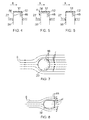
- Figures 4 to 6 show three variants of the discharge outlet member 38.
- the discharge outlet member 38 serves as a noise attenuator, and so mitigates the interruption in the acoustic material of the inner wall 27 at the opening 33. This is achieved by the acoustic liner 31 of open cellular form on the end wall 32, with the size and disposition of the cells being optimised for noise attenuation.
- a pressure diaphragm 56 is situated within the discharge outlet member 38 a short distance beneath the end wall 32. The pressure diaphragm serves to direct air flow from the bleed valve 34 to the slots 48 in a desired manner.
- the pressure diaphragm is oblique to the transverse plane of the discharge outlet member 38, assisting the change of direction of the air flow towards the slots 48.
- the pressure diaphragm is parallel to the transverse plane (and consequently to the end wall 32), and is spaced below the end wall 32 by a distance d to avoid turbulent flow in the region of the discharge outlet member 38 above the slots 48.
- the pressure diaphragm 56 is situated between the end wall 32 and the slots 48.
- the openings such as the slots 48 in the skirt 44 may be arranged in any suitable manner to achieve a desired discharge plume from the discharge outlet member 38 when deployed.
- the slots 48 may be replaced, or supplemented, by small holes on the upstream, downstream or side regions of the skirt 44.
- the pressure diaphragm 56 may be dispensed with in some circumstances, as shown in Figure 6 .
- Figure 7 represents streamlines of the flow B when combined with flow F discharged by the bleed assembly 30 through the slots 48.
- Figure 7 shows a bleed assembly 30 having a circular cross-sectional shape, in accordance with Figures 2 and 3 .
- the profile of the bleed assembly, and in particular the discharge outlet member 38 may be tailored to suit the aerodynamic requirements of the bypass duct 22.
- the discharge outlet member 38 has a rounded leading surface 58 directed upstream with respect to the bleed flow B, and a flat, transverse downstream surface 16 in which the slots 48 are provided.
- a bleed assembly as described above provides minimal drag on the bypass flow B when the discharge outlet member 38 is retracted, as shown in Figure 2 , because the end wall 32 lies substantially flush with the surrounding inner wall 27. Furthermore, because the end wall 32 is provided with the acoustic liner 31, there is a minimal loss of the acoustic properties of the liner of the inner wall 27.
Abstract
A flow discharge device, such as a bleed assembly in a gas turbine engine, comprises a discharge outlet member 38 having a skirt 44 which is accommodated telescopically in a housing 36 so as to be displaceable with respect to a wall 27 of a duct 22 from a retracted position (Figure 2 ) in which slots 48 in the skirt 44 lie outside the duct 22, and an extended position (Figure 3 ) in which the slots 48 open into the duct 22 for the discharge of a secondary fluid into the flow in the duct 22. The discharge outlet member 38 is moved to the extended position by the pressure of the secondary fluid acting on a silencer element 46. A spring 52 returns the discharge outlet member to the retracted position when the flow of the secondary fluid is terminated.
Description
- This invention relates to a flow discharge device in a duct, and is particularly, although not exclusively, concerned with such a device for discharging compressor bleed air into a bypass duct of a gas turbine engine.
- When a gas turbine engine is operating under transient conditions, for example when decelerating, it may be necessary to bleed air at high pressure from the core gas flow through the engine. Such air may be discharged through a discharge device into a bypass flow within the engine. Bleed valves are provided to control the discharge of air. The flow of bleed air from the core gas flow into the bypass flow takes place over a substantial pressure drop, and can generate significant noise. It is therefore usual for the discharge device to be configured so as to reduce the noise. A typical measure is to discharge the bleed air into the bypass duct through a perforated plate, sometimes referred to as a "pepper pot" which is flush with the wall of the bypass duct. The pepper pot serves to break the single body of air flowing towards the bypass duct into a large number of smaller jets which promote small-scale turbulence and hence quicker mixing with the main flow through the bypass duct.
- The individual flow jets from the pepper pot holes tend to coalesce into a single plume, and consequently the bleed flow does not mix rapidly with the main flow. The plume also blocks the main flow and creates a wake behind it. If the pepper pot is flush with the wall of the bypass duct hot air and high-energy vortices in the wake can flow into contact with the bypass duct surfaces creating "hot spots" where components can be overheated and consequently damaged.
-
US 7434405 discloses a bleed diffuser for a gas turbine engine which is extendable so as to project beyond a wall of the gas turbine engine into an air flow, when air is to be discharged from the bleed diffuser. Extension of the bleed diffuser is achieved by means of an actuator such as an electrical motor. Bleed diffusers need to be deployed rapidly, for relatively short periods, and consequently a large and powerful actuator is required. Also, the control of the actuator has to be coordinated with that of the rest of the bleed system, introducing complexity and reliability issues. - According to the present invention there is provided a flow discharge device for discharging flow into a duct, the device comprising a discharge outlet member having at least one discharge aperture, the outlet member being displaceable by the pressure of a secondary fluid in a secondary fluid source from a retracted position in which the discharge aperture is situated outside the duct, to an extended position in which the discharge aperture is situated within the duct, whereby the secondary fluid flow is discharged through the aperture into a main fluid flow travelling along the duct.
- The present invention thus enables the discharge outlet member to be moved automatically into the extended position by the pressure of the secondary fluid, without requiring any additional control systems or actuators.
- The discharge outlet member may be mounted displaceably in a housing which is secured with respect to a wall of the duct. The housing may be provided with a bleed valve which, when open, provides communication between the interior of the housing and the secondary fluid source.
- The discharge outlet member may comprise an end wall and a skirt which extends from the end wall and telescopically engages the housing, the aperture being provided in the skirt. In the retracted position of the discharge outlet member, the end wall may lie substantially flush with the duct wall. The aperture may be one of an array of apertures which permit the flow of the secondary fluid from the interior of the skirt to the duct when the discharge outlet member is in the extended position. The aperture, or at least one of the apertures, may be in the form of a slot.
- A silencer element may be disposed in the skirt at a position away from the end wall, the secondary fluid acting on the silencer element to displace the outlet member to the extended position.
- Return means may be provided for returning the discharge outlet member to the retracted position when isolated from the secondary fluid source. The return means may be resilient means, for example a spring acting between the silencer element and an abutment which is secured with respect to the housing. A damping means may be provided for damping displacement of the discharge outlet member towards the retracted and/or extended positions.
- The present invention also provides a gas turbine engine provided with a flow discharge device as defined above, the duct being a bypass duct of the gas turbine engine, and the discharge device comprising a compressor bleed assembly.
- For a better understanding of the present invention, and to show more clearly how it may be carried into effect, reference will now be made, by way of example, to the accompanying drawings, in which:
-
Figure 1 is a schematic sectional view of a gas turbine engine; -
Figure 2 shows a bleed assembly of the engine ofFigure 1 in a retracted condition; -
Figure 3 corresponds toFigure 2 but shows the bleed assembly in an extended condition; -
Figures 4 to 6 show three variants of the bleed assembly ofFigures 1 and2 ; and -
Figures 7 and 8 represent air flow patterns generated in use of two embodiments of the bleed valve assembly. - Referring to
Figure 1 , a ducted fan gas turbine engine generally indicated at 10 has a principal and rotational axis 11. The engine 10 comprises, in axial flow series, anair intake 12, apropulsive fan 13, anintermediate pressure compressor 14, a high-pressure compressor 15,combustion equipment 16, a high-pressure turbine 17, anintermediate pressure turbine 18, a low-pressure turbine 19 and acore exhaust nozzle 20. Anacelle 21 generally surrounds the engine 10 and defines theintake 12, abypass duct 22 and anexhaust nozzle 23. - The gas turbine engine 10 works in the conventional manner so that air entering the
intake 12 is accelerated by thefan 13 to produce two air flows: a first airflow A into theintermediate pressure compressor 14 and a second airflow B which passes through thebypass duct 22 to provide propulsive thrust. Theintermediate pressure compressor 14 compresses the airflow A directed into it before delivering that air to thehigh pressure compressor 15 where further compression takes place. - The compressed air exhausted from the high-
pressure compressor 15 is directed into thecombustion equipment 16 where it is mixed with fuel and the mixture combusted. The resultant hot combustion products then expand through, and thereby drive, the high, intermediate and low-pressure turbines nozzle 20 to provide additional propulsive thrust. The high, intermediate and low-pressure turbines intermediate pressure compressors fan 13 by suitable interconnecting shafts. - The
fan 13 is circumferentially surrounded by a structural member in the form of afan casing 24, which is supported by an annular array ofoutlet guide vanes 28. Thefan casing 24 comprises arigid containment casing 25 and attached inwardly thereto is arear fan casing 26. Thebypass duct 22 is defined between therear fan casing 26 and aninner wall 27. Theinner wall 27 is spaced outwardly from acompressor casing structure 29 which accommodates the intermediate andhigh pressure compressors - During engine operation and particularly when changing rotational speed at low power it is important to ensure that the pressure ratio across each
compressor - To maintain a preferred pressure difference across a
compressor compressor assemblies 30 are provided to release pressure from an upstream part of acompressor bleed assembly 30 and engine operability are described in "The Jet Engine" 6th Edition, 2005, Rolls-Royce plc, pages 79-80, and details of such operation will therefore only be briefly mentioned herein. - The
bleed assembly 30 comprises ableed valve 34 which communicates at one end with therespective compressor casing structure 29 and is connected at its other end to ahousing 36. Adischarge outlet member 38discharge outlet member 38 is mounted within thehousing 36. - The
housing 36 is supported between theinner wall 27 of thebypass duct 22, and thecasing structure 29. Afire seal 40 carried by an out-turned flange of thehousing 36, contacts the radially inner surface of theinner wall 27, at arecess 42 surrounding the opening 33. - The
housing 36 is of cylindrical form, but narrows to a reduced diameter at its radially inner end, where thebleed valve 34 is situated. The bleedvalve 34 is received in an opening in thecasing structure 29 so that its lower end (in the orientation shown inFigure 2 ) is exposed to the air flow in thecompressor housing 36 thus serves as a bleed duct providing communication between thecompressor bypass duct 22 when thebleed valve 34 is open. - The upper region of the
bleed valve 34 opens within the interior of thehousing 36. Thedischarge outlet member 38 comprises anend wall 32 and a depending skirt 44 (Figure 3 ). Theend wall 32 is provided with anacoustic liner 31 facing into thebypass duct 22. A similar acoustic liner may be provided on theinner wall 27. The dependingskirt 44 forms a telescopic fit within thehousing 36 and, at its lower end (in the orientation shown inFigure 2 ), is provided with asilencer element 46 having a cellular structure, so that air flow through the silencer element follows a tortuous path. This creates a significant pressure drop, with associated noise attenuation, when flow takes place across thesilencer element 46. - The
skirt 44 is provided with an array ofapertures 48 which, in the embodiment shown inFigures 2 and 3 , comprise slots extending in the axial direction of the skirt. Theslots 48 are disposed on the downstream side of theskirt 44, with respect to the flow direction B in thebypass duct 22. - A
rod 50 projects into thehousing 36, and into theskirt 44, from thebypass valve 34. A spring anddamper unit 52, represented diagrammatically inFigures 2 and 3 , acts between the silencer element and an abutment, in the form of a projectingflange 54, at the free end of therod 50. - In operation of the engine shown in
Figure 1 , parts of the core engine air flow A may be diverted through thebleed assembly 30 in order to optimise the performance of therespective compressors bleed valve 34 of therespective bleed assembly 30. Theopen bleed valve 34 permits air at high pressure to pass through thecasing structure 29 into thehousing 36. Although the introduced air can pass through thesilencer element 46, a pressure drop is nevertheless established across thesilencer element 46, which displaces it away from thebleed valve 34 against the resilience of the spring in the spring/damper unit 52. The entiredischarge outlet member 38 is thus displaced from the retracted condition shown inFigure 2 to the extended position shown inFigure 3 , in which theend wall 32 is situated away from theinner wall 27. Consequently, air from thecompressor bypass valve 34 passes across thesilencer element 46 into thedischarge outlet member 38 and thence, through theslots 48, into the bypass flow B in thebypass duct 22. The lower ends of theslots 48 are spaced above theinner wall 27, and so the relatively hot discharging flow from thedischarge outlet member 38 enters the bypass flow B away from the inner andouter walls outer walls walls - When the
bleed valve 34 is closed, the interior of thehousing 36 is isolated from thecompressor silencer element 46 reduces. The spring in the spring/damper unit 52 then drives thedischarge outlet member 38 to the retracted position as shown inFigure 2 . -
Figures 4 to 6 show three variants of thedischarge outlet member 38. In all three variants, thedischarge outlet member 38 serves as a noise attenuator, and so mitigates the interruption in the acoustic material of theinner wall 27 at theopening 33. This is achieved by theacoustic liner 31 of open cellular form on theend wall 32, with the size and disposition of the cells being optimised for noise attenuation. In the embodiments ofFigures 4 and 5 , apressure diaphragm 56 is situated within the discharge outlet member 38 a short distance beneath theend wall 32. The pressure diaphragm serves to direct air flow from thebleed valve 34 to theslots 48 in a desired manner. In the embodiment ofFigure 4 , the pressure diaphragm is oblique to the transverse plane of thedischarge outlet member 38, assisting the change of direction of the air flow towards theslots 48. In the variant ofFigure 5 , the pressure diaphragm is parallel to the transverse plane (and consequently to the end wall 32), and is spaced below theend wall 32 by a distance d to avoid turbulent flow in the region of thedischarge outlet member 38 above theslots 48. In both of the variants ofFigures 4 and 5 , thepressure diaphragm 56 is situated between theend wall 32 and theslots 48. - The openings such as the
slots 48 in theskirt 44 may be arranged in any suitable manner to achieve a desired discharge plume from thedischarge outlet member 38 when deployed. For example, theslots 48 may be replaced, or supplemented, by small holes on the upstream, downstream or side regions of theskirt 44. - The
pressure diaphragm 56 may be dispensed with in some circumstances, as shown inFigure 6 . -
Figure 7 represents streamlines of the flow B when combined with flow F discharged by thebleed assembly 30 through theslots 48.Figure 7 shows ableed assembly 30 having a circular cross-sectional shape, in accordance withFigures 2 and 3 . However, as indicated inFigure 8 , the profile of the bleed assembly, and in particular thedischarge outlet member 38, may be tailored to suit the aerodynamic requirements of thebypass duct 22. Thus, in the embodiment shown inFigure 8 , thedischarge outlet member 38 has a rounded leading surface 58 directed upstream with respect to the bleed flow B, and a flat, transversedownstream surface 16 in which theslots 48 are provided. - A bleed assembly as described above provides minimal drag on the bypass flow B when the
discharge outlet member 38 is retracted, as shown inFigure 2 , because theend wall 32 lies substantially flush with the surroundinginner wall 27. Furthermore, because theend wall 32 is provided with theacoustic liner 31, there is a minimal loss of the acoustic properties of the liner of theinner wall 27. By deploying thedischarge outlet member 38 into the bypass flow B, the discharge of the hot air from thecompressors outer walls slots 48 or other openings, avoids impingement on the inner andouter walls - Because the deployment of the
discharge outlet member 38 is achieved by the high-pressure air passing through thebleed valve 34, high reliability can be assured, with deployment occurring only when thebleed valve 34 is open.
Claims (14)
- A flow discharge device for discharging flow into a duct (22), the device comprising a discharge outlet member (38) having at least one discharge aperture (48), the outlet member (38) being displaceable by the pressure of a secondary fluid in a secondary fluid source from a retracted position in which the discharge aperture is situated outside the duct, to an extended position in which the discharge aperture is situated within the duct, whereby the secondary fluid flow is discharged through the aperture into a main fluid flow travelling along the duct.
- A flow discharge device as claimed in claim 1, in which the discharge outlet member (38) is mounted displaceably in a housing (36) secured with respect to the wall of the duct (22).
- A flow discharge device as claimed in claim 2, in which the housing (36) has a valve (34) which is openable to provide communication between the interior of the housing and the secondary fluid source.
- A flow discharge device as claimed in claim 2 or 3, in which the discharge outlet member (38) comprises an end wall (32), and a skirt (44) which extends from the end wall (32) and telescopically engages the housing (36).
- A flow discharge device as claimed in claim 3, in which the end wall (32) is provided with an acoustic liner (31).
- A flow discharge device as claimed in claim 3 or 4, in which the or each discharge aperture (48) is provided in the skirt (44).
- A flow discharge device as claimed in claim 6, in which the discharge aperture (48) is one of an array of discharge apertures (48) provided in the skirt (44).
- A flow discharge device as claimed in claim 6 or 7, in which the discharge aperture (48), or at least one of the discharge apertures, comprises a slot.
- A flow discharge device as claimed in any one of claims 4 to 8, in which a silencer element (46) is disposed in the skirt (44) at a position away from the end wall (32), the secondary fluid acting on the silencer element (46) to displace the outlet member (38) to the extended position.
- A flow discharge device as claimed in any one of the preceding claims, in which return means is provided for returning the discharge outlet member (38) to the retracted position when the discharge outlet member (38) is isolated from the secondary fluid source.
- A flow discharge device as claimed in claim 10, in which the return means comprises resilient means.
- A flow discharge device as claimed in claim 11 when appendant to claim 9, in which the resilient means comprises a spring acting between the silencer element (46) and an abutment which is secured with respect to the housing (36).
- A flow discharge device as claimed in any one of claims 10 to 12, in which a damping means (52) is provided for damping displacement of the discharge outlet member (38) towards at least one of the retracted and extended positions.
- A gas turbine engine provided with a flow discharge device in accordance with any one of the preceding claims, the duct (22) being a bypass duct of the gas turbine engine, and the discharge device comprising a compressor bleed assembly (30).
Applications Claiming Priority (1)
| Application Number | Priority Date | Filing Date | Title |
|---|---|---|---|
| GB0912171A GB0912171D0 (en) | 2009-07-14 | 2009-07-14 | A flow discharge device |
Publications (1)
| Publication Number | Publication Date |
|---|---|
| EP2275655A2 true EP2275655A2 (en) | 2011-01-19 |
Family
ID=41057892
Family Applications (1)
| Application Number | Title | Priority Date | Filing Date |
|---|---|---|---|
| EP20100167136 Withdrawn EP2275655A2 (en) | 2009-07-14 | 2010-06-24 | A flow discharge device |
Country Status (3)
| Country | Link |
|---|---|
| US (1) | US8511095B2 (en) |
| EP (1) | EP2275655A2 (en) |
| GB (1) | GB0912171D0 (en) |
Cited By (3)
| Publication number | Priority date | Publication date | Assignee | Title |
|---|---|---|---|---|
| EP2966288A1 (en) * | 2014-07-11 | 2016-01-13 | Rolls-Royce plc | Ventilation inlet |
| FR3064029A1 (en) * | 2017-03-15 | 2018-09-21 | Safran Aircraft Engines | JOINT FOR SEALING LIGHT AND ASSEMBLY COMPRISING SUCH A JOINT |
| WO2020043977A1 (en) | 2018-08-30 | 2020-03-05 | Safran Aircraft Engines | Outlet for ejecting a hot gas through an aircraft engine wall |
Families Citing this family (4)
| Publication number | Priority date | Publication date | Assignee | Title |
|---|---|---|---|---|
| US20140338360A1 (en) * | 2012-09-21 | 2014-11-20 | United Technologies Corporation | Bleed port ribs for turbomachine case |
| US10113484B2 (en) | 2015-12-21 | 2018-10-30 | General Electric Company | High pressure exhaust muffling device with multiple sources |
| GB201808852D0 (en) * | 2018-05-31 | 2018-07-18 | Rolls Royce Plc | Gas turbine engine |
| US11118705B2 (en) | 2018-08-07 | 2021-09-14 | General Electric Company | Quick connect firewall seal for firewall |
Citations (1)
| Publication number | Priority date | Publication date | Assignee | Title |
|---|---|---|---|---|
| US7434405B2 (en) | 2005-05-31 | 2008-10-14 | United Technologies Corporation | Bleed diffuser for gas turbine engine |
Family Cites Families (27)
| Publication number | Priority date | Publication date | Assignee | Title |
|---|---|---|---|---|
| US3125119A (en) * | 1964-03-17 | richgels | ||
| US2206356A (en) * | 1936-10-13 | 1940-07-02 | Walter B Hutchings | Check valve |
| US2657899A (en) * | 1948-12-31 | 1953-11-03 | Hartford Nat Bank & Trust Co | Cylindrical valve body comprising one or more apertures provided in the wall thereof |
| US3202177A (en) * | 1961-11-20 | 1965-08-24 | Int Harvester Co | Pressure regulating valve |
| US3234959A (en) * | 1963-07-19 | 1966-02-15 | Feinberg Maurice | Check valve device |
| US3540484A (en) * | 1968-01-05 | 1970-11-17 | Titus Mfg Corp | Constant volume regulators and air distribution apparatus embodying same |
| US3943969A (en) * | 1975-04-25 | 1976-03-16 | Albert Rubin | Positive acting check valve of polyvinylchloride to open in response to predetermined line pressure |
| FR2315051A1 (en) * | 1975-06-20 | 1977-01-14 | Bertin & Cie | SOUNDPROOF VALVE |
| GB1547168A (en) * | 1975-09-25 | 1979-06-06 | British Gas Corp | Gas-flow noise reduction systems |
| US4537277A (en) * | 1982-12-03 | 1985-08-27 | The Secretary Of State For Defence In Her Britannic Majesty's Government Of The United Kingdom Of Great Britain And Northern Ireland | Silencer for high velocity gas flow |
| US5014746A (en) * | 1990-01-16 | 1991-05-14 | Westinghouse Electric Corp. | Hole pattern for valve muffler |
| US5362266A (en) * | 1993-06-23 | 1994-11-08 | Doug Brogdon | Flushmaster fresh water flushing system |
| US5477673A (en) * | 1994-08-10 | 1995-12-26 | Pratt & Whitney Canada Inc. | Handling bleed valve |
| US6122905A (en) * | 1998-02-13 | 2000-09-26 | Pratt & Whitney Canada Corp. | Compressor bleed valve |
| GB2376515B (en) * | 2001-06-13 | 2004-09-29 | Rolls Royce Plc | Bleed valve assembly |
| US6565313B2 (en) * | 2001-10-04 | 2003-05-20 | United Technologies Corporation | Bleed deflector for a gas turbine engine |
| US6622819B2 (en) * | 2001-10-15 | 2003-09-23 | Steven M. Reynolds | Sound attenuator for pneumatic exhaust |
| CA2468141A1 (en) * | 2001-11-21 | 2003-06-05 | Dunlop Aerospace Limited | Noise attenuator arrangement |
| US7438131B2 (en) * | 2004-08-06 | 2008-10-21 | Baker Hughes Incorporated | Expandable injector pipe |
| GB0425794D0 (en) * | 2004-11-24 | 2004-12-22 | Rolls Royce Plc | Acoustic damper |
| US7540144B2 (en) * | 2005-10-21 | 2009-06-02 | Pratt & Whitney Canada Corp. | Bleed valve for a gas turbine engine |
| US7555905B2 (en) * | 2006-03-28 | 2009-07-07 | United Technologies Corporation | Self-actuating bleed valve for gas turbine engine |
| US8052129B2 (en) * | 2006-04-25 | 2011-11-08 | Youd Jason B | Steel spring damper |
| US7946104B2 (en) * | 2006-05-12 | 2011-05-24 | Rohr, Inc. | Bleed air relief system for engines |
| GB0614360D0 (en) * | 2006-07-20 | 2006-08-30 | Rolls Royce Plc | Aeroengine bleed valve |
| GB0616847D0 (en) * | 2006-08-25 | 2006-10-04 | Rolls Royce Plc | Aeroengine bleed valve |
| US7797945B2 (en) * | 2006-09-06 | 2010-09-21 | Honeywell International Inc. | Bleed valve outlet flow deflector |
-
2009
- 2009-07-14 GB GB0912171A patent/GB0912171D0/en not_active Ceased
-
2010
- 2010-06-24 EP EP20100167136 patent/EP2275655A2/en not_active Withdrawn
- 2010-06-24 US US12/822,705 patent/US8511095B2/en not_active Expired - Fee Related
Patent Citations (1)
| Publication number | Priority date | Publication date | Assignee | Title |
|---|---|---|---|---|
| US7434405B2 (en) | 2005-05-31 | 2008-10-14 | United Technologies Corporation | Bleed diffuser for gas turbine engine |
Cited By (8)
| Publication number | Priority date | Publication date | Assignee | Title |
|---|---|---|---|---|
| EP2966288A1 (en) * | 2014-07-11 | 2016-01-13 | Rolls-Royce plc | Ventilation inlet |
| US10006372B2 (en) | 2014-07-11 | 2018-06-26 | Rolls-Royce Plc | Ventilation inlet |
| FR3064029A1 (en) * | 2017-03-15 | 2018-09-21 | Safran Aircraft Engines | JOINT FOR SEALING LIGHT AND ASSEMBLY COMPRISING SUCH A JOINT |
| US10598037B2 (en) | 2017-03-15 | 2020-03-24 | Safran Aircraft Engines | Air-fire seal and assembly comprising such a seal |
| US11098607B2 (en) | 2017-03-15 | 2021-08-24 | Safran Aircraft Engines | Air-fire seal and assembly comprising such a seal |
| WO2020043977A1 (en) | 2018-08-30 | 2020-03-05 | Safran Aircraft Engines | Outlet for ejecting a hot gas through an aircraft engine wall |
| FR3085438A1 (en) * | 2018-08-30 | 2020-03-06 | Safran Aircraft Engines | EJECTION MOUTH OF A HOT GAS THROUGH AN AIRCRAFT ENGINE WALL |
| US11421605B2 (en) | 2018-08-30 | 2022-08-23 | Safran Aircraft Engines | Outlet for ejecting a hot gas through an aircraft engine wall |
Also Published As
| Publication number | Publication date |
|---|---|
| US8511095B2 (en) | 2013-08-20 |
| GB0912171D0 (en) | 2009-08-26 |
| US20110011477A1 (en) | 2011-01-20 |
Similar Documents
| Publication | Publication Date | Title |
|---|---|---|
| US8511095B2 (en) | Flow discharge device | |
| US8550208B1 (en) | High pressure muffling devices | |
| JP5306638B2 (en) | Turbine engine with flow control fan and method of operation | |
| US3879941A (en) | Variable cycle gas turbine engine | |
| EP2372107B1 (en) | Flow discharge device | |
| US6622475B2 (en) | Bleed system driven in simplified manner for a turbojet or turboprop engine | |
| CA2638677C (en) | Apparatus and method for suppressing dynamic pressure instability in bleed duct | |
| CN106870161B (en) | Turbofan engine and bleed system | |
| JP4949154B2 (en) | Gas exhaust nozzle of bypass turbomachine with exhaust cross section or throat cross section that can be changed by moving secondary cowl | |
| US9476362B2 (en) | Turbomachine with bleed valves located at the intermediate case | |
| EP2944769A1 (en) | Bifurcation fairing | |
| US8430202B1 (en) | Compact high-pressure exhaust muffling devices | |
| US20070000232A1 (en) | Gas turbine engine and method of operating same | |
| EP2123863B1 (en) | Pre-diffuser for centrifugal compressor | |
| US8336288B2 (en) | Gas-turbine engine in particular aircraft engine | |
| EP1998027B1 (en) | Gas turbine engine comprising a nacelle compartment plenum for bleed air flow delivery system | |
| US20100236256A1 (en) | Flow discharge device | |
| JP2008196492A (en) | Relief device for turbo jet engine, and turbo jet engine equipped therewith | |
| US8596076B1 (en) | Variable pressure ratio gas turbine engine | |
| US11828469B2 (en) | Adaptive trapped vortex combustor | |
| CN117307355A (en) | Compressor bypass discharge system for ducted fan engines | |
| CA2652708A1 (en) | Flow-control technique to vector bulk flow leaving a vane |
Legal Events
| Date | Code | Title | Description |
|---|---|---|---|
| PUAI | Public reference made under article 153(3) epc to a published international application that has entered the european phase |
Free format text: ORIGINAL CODE: 0009012 |
|
| AK | Designated contracting states |
Kind code of ref document: A2 Designated state(s): AL AT BE BG CH CY CZ DE DK EE ES FI FR GB GR HR HU IE IS IT LI LT LU LV MC MK MT NL NO PL PT RO SE SI SK SM TR |
|
| AX | Request for extension of the european patent |
Extension state: BA ME RS |
|
| RAP1 | Party data changed (applicant data changed or rights of an application transferred) |
Owner name: ROLLS-ROYCE PLC |
|
| STAA | Information on the status of an ep patent application or granted ep patent |
Free format text: STATUS: THE APPLICATION HAS BEEN WITHDRAWN |
|
| 18W | Application withdrawn |
Effective date: 20160121 |