EP2275629B1 - Window bolt and window therewith - Google Patents
Window bolt and window therewith Download PDFInfo
- Publication number
- EP2275629B1 EP2275629B1 EP09180714.9A EP09180714A EP2275629B1 EP 2275629 B1 EP2275629 B1 EP 2275629B1 EP 09180714 A EP09180714 A EP 09180714A EP 2275629 B1 EP2275629 B1 EP 2275629B1
- Authority
- EP
- European Patent Office
- Prior art keywords
- bolt
- window frame
- window
- rod
- seat
- Prior art date
- Legal status (The legal status is an assumption and is not a legal conclusion. Google has not performed a legal analysis and makes no representation as to the accuracy of the status listed.)
- Not-in-force
Links
Images



Classifications
-
- E—FIXED CONSTRUCTIONS
- E05—LOCKS; KEYS; WINDOW OR DOOR FITTINGS; SAFES
- E05C—BOLTS OR FASTENING DEVICES FOR WINGS, SPECIALLY FOR DOORS OR WINDOWS
- E05C1/00—Fastening devices with bolts moving rectilinearly
- E05C1/02—Fastening devices with bolts moving rectilinearly without latching action
- E05C1/04—Fastening devices with bolts moving rectilinearly without latching action with operating handle or equivalent member rigid with the bolt
Definitions
- the present invention relates to a bolt for a window, as well as relates to a window with said bolt.
- window bolts usually contain a bolt rod and a bolt seat, and the bolt seat is mounted on the window frame by screws, while the bolt rod is able to move back and forth on said bolt seat, and one end of said bolt rod is able to head out of said window frame so that it can cooperate with the locking structure of another window frame in order to limit the movement between these two window frames.
- the locking structure can be a notch or a bolt nose made of metal, as disclosed e.g. in Chinese utility model No. ZL90221914.6 (grant No. CN20811413U ), and in Chinese utility model application No. ZL92106851.4 (grant No. CN1067474A ).
- Patent document WO 2007/070127 A1 discloses a window bolt with a bolt rod and a bolt seat.
- the method of fixing the bolt seat on the window frame is comparatively simple, and it is easy for the bolt seat to become loose during the use of the bolt, which reduces the precision of the position between the bolt rod and the jack or slot of the bolt, and this affects the normal operation of the bolt; Secondly, since the connecting method of the bolt rod and the bolt seat is a little bit complicated, it takes enough time to finish the assembling.
- the first technical problem that the present invention intends to solve is to provide a window bolt, of which the bolt seat is fixed solidly, and of which the bolt seat and the rod can be assembled easily.
- the second technical problem that the present invention intends to solve is to provide a window with a bolt, of which the bolt seat is fixed solidly, and of which the bolt seat and the rod can be assembled easily.
- a window bolt comprising a bolt rod and a bolt seat, wherein said bolt seat is arranged on a window frame and said bolt rod is able to move back and forth on said bolt seat, one end of said bolt rod is able to head out of said window frame so that it cooperates with the jack or slot of another window frame in order to establish the connection between these two window frames
- said bolt seat is in the form of a long strip shape extending along a longitudinal direction
- its back end has fixing means for fixing to a first side of the window frame
- its front end has two sides folded downwards respectively in order to form a baffle part
- said frond end further has a toothed part which is adapted to be fixed against a second side of an window frame, the toothed part projecting backward in the longitudinal direction and is formed in front of said front end of said baffle part
- the middle part of the bolt seat has a guide hole along the direction of its length, and another end of said bolt rod
- said fixing means may be in the form of a screw hole which is used to fix a screw on the first side of said window frame.
- said actuation button may have a width along the length of said bolt rod and has a length perpendicular to the length of said bolt rod, wherein the length of said guide slot is between said width and length of said actuation button, and when said actuation button projects through said guide slot and said bolt rod is rotated to the position which is parallel to said bolt seat, said actuation button can not be separated from said guide slot perpendicularly due to the fact that the width of said guide slot is smaller than the length of said actuation button.
- the upper side of said bolt rod may have projecting friction blocks, and during the back and forth movement of said bolt rod, there is a friction contact between said friction blocks and the lower side of said bolt seat.
- Said toothed parts may project from the lower side of said side walls and may be in the same plane as the latter, or said toothed part may be folded substantially in the form of L-shape at the lower and front of said side walls.
- the invention also provides for a window with a bolt as described above, said window comprising an interior window frame and an exterior window frame, wherein:
- the advantages of this invention are as follows:
- the bolt seat is fixed on the window frame through two different positions and the movement of each position is limited, which greatly improves the assemble immobility of the bolt seat. Besides, only by passing though the bolt seat can the actuation button of bolt rod be assembled easily.
- a window with a bolt of the embodiment 1 contains an interior window sash 5, a bolt 10 arranged on the interior window sash 5 and exterior window frame 6, wherein the interior window sash 5 consists of two erect window frames 53 arranged longitudinally, a upper horizontal frame 51 and a lower horizontal frame 52 arranged horizontally, a secured plugging means 61 for the bolt 10 is arranged on the inner wall of the exterior window frame 6, and the bolt 10 contains a bolt rod 1 and a bolt seat 2, and a notch 511 for holding the bolt rod 1 is formed on the upper horizontal frame 51, and the bolt seat 2 is arranged at the level of the end of the notch 511, and the bolt rod 1 is able to move back and forth on the bolt seat 2.
- the bolt seat 2 has the shape of a long strip, and its back end has a screw hole 21 which is used to make a screw 30 to be fixed on the upper side of the upper horizontal frame 51, and its front end has toothed or barbed parts 4 which can be fixed against the lateral side of the upper horizontal frame 51, and its middle part is near the screw hole 21 and has a guide slot 22 along the direction of its length.
- Two sides of the front end of said bolt seat 2 are folded downwards respectively so as to form side walls 3, and the toothed parts 4 projects from the lower side of said side walls 3 and are in the same plane of the latter.
- One end of the bolt rod 1 is able to head out of the interior window sash 5 so that it can cooperate with the secured plugging means 61 of the external window frame in order to establish the connection between the interior window sash 5 and the external window frame 6, while the other end has a projecting actuation button 11 which projects through the guide slot 22 and is able to move back and forth in the guide slot 22.
- the upper side of the bolt rod 1 has projecting friction blocks 12, and during the back and forth movement of the bolt rod 1, there is a friction contact between the friction blocks 12 and the bolt seat 2.
- the actuation button 11 has a width along the length of the bolt rod and has a length perpendicular to the length of said bolt rod, wherein the length of the guide slot 22 is between the width and length of the actuation button 11, and when the actuation button 11 projects through the guide slot 22 and the bolt rob 1 is rotated to the position which is parallel to the bolt seat 2, the actuation button 11 cannot be separated from the guide slot 22 perpendicularly due to the fact that the width of the guide slot 22 is smaller than the length of the actuation button 11.
- the assembly process is shown in figure 6 to 8 .
- Embodiment 2 is similar to embodiment 1 and distinguishes over embodiment 1 only by the fact that the toothed parts 4' are folded substantially in the form of an L at the lower portion of the front end of the side walls 3. More precisely, each toothed part 4' may include a tab which extends outwardly from the front end of the corresponding side wall 3, the free end of this tab being extended rearward at least one tooth - here two teeth 41, 42.
- Embodiment 3 is also similar to embodiment 1 and distinguishes over embodiment 1 only by the fact that the rod 1 comprises two detent means 13, 14 longitudinally distant from each other, each of said detent means 13, 14 being adapted to provide a locking function by cooperation with complementary detent means 23 provided on said bolt seat 2".
- each of said two detent means 13, 14 may be formed by a hole at a side surface of said rod 1, and said complementary detent means may be formed by a lug 24 provided on an inner face of a flexible tongue 23 which is cut out in the side wall 3 of the bolt seat 2".
Landscapes
- Engineering & Computer Science (AREA)
- Mechanical Engineering (AREA)
- Window Of Vehicle (AREA)
- Wing Frames And Configurations (AREA)
- Door And Window Frames Mounted To Openings (AREA)
Description
- The present invention relates to a bolt for a window, as well as relates to a window with said bolt.
- In the prior art, window bolts usually contain a bolt rod and a bolt seat, and the bolt seat is mounted on the window frame by screws, while the bolt rod is able to move back and forth on said bolt seat, and one end of said bolt rod is able to head out of said window frame so that it can cooperate with the locking structure of another window frame in order to limit the movement between these two window frames. The locking structure can be a notch or a bolt nose made of metal, as disclosed e.g. in Chinese utility model No.
ZL90221914.6 CN20811413U ), and in Chinese utility model application No.ZL92106851.4 CN1067474A ). Patent documentWO 2007/070127 A1 discloses a window bolt with a bolt rod and a bolt seat. - The method of fixing the bolt seat on the window frame, disclosed by the applications mentioned above, is comparatively simple, and it is easy for the bolt seat to become loose during the use of the bolt, which reduces the precision of the position between the bolt rod and the jack or slot of the bolt, and this affects the normal operation of the bolt; Secondly, since the connecting method of the bolt rod and the bolt seat is a little bit complicated, it takes enough time to finish the assembling.
- In light of prior art mentioned above, the first technical problem that the present invention intends to solve is to provide a window bolt, of which the bolt seat is fixed solidly, and of which the bolt seat and the rod can be assembled easily.
- Also in light of prior art mentioned above, the second technical problem that the present invention intends to solve is to provide a window with a bolt, of which the bolt seat is fixed solidly, and of which the bolt seat and the rod can be assembled easily.
- The technical scheme which can solve these problems used by the present invention is as follows: a window bolt comprising a bolt rod and a bolt seat, wherein said bolt seat is arranged on a window frame and said bolt rod is able to move back and forth on said bolt seat, one end of said bolt rod is able to head out of said window frame so that it cooperates with the jack or slot of another window frame in order to establish the connection between these two window frames, wherein said bolt seat is in the form of a long strip shape extending along a longitudinal direction, its back end has fixing means for fixing to a first side of the window frame, and its front end has two sides folded downwards respectively in order to form a baffle part, said frond end further has a toothed part which is adapted to be fixed against a second side of an window frame, the toothed part projecting backward in the longitudinal direction and is formed in front of said front end of said baffle part, and wherein the middle part of the bolt seat has a guide hole along the direction of its length, and another end of said bolt rod has a projecting actuation part which projects through said guide hole and is able to move back and forth in said guide hole.
- Preferably said fixing means may be in the form of a screw hole which is used to fix a screw on the first side of said window frame.
- In order to facilitate the assembling, meanwhile, to ensure that it is not easy for the bolt rod to detach from the bolt seat after the assembling, said actuation button may have a width along the length of said bolt rod and has a length perpendicular to the length of said bolt rod, wherein the length of said guide slot is between said width and length of said actuation button, and when said actuation button projects through said guide slot and said bolt rod is rotated to the position which is parallel to said bolt seat, said actuation button can not be separated from said guide slot perpendicularly due to the fact that the width of said guide slot is smaller than the length of said actuation button.
- The upper side of said bolt rod may have projecting friction blocks, and during the back and forth movement of said bolt rod, there is a friction contact between said friction blocks and the lower side of said bolt seat.
- Said toothed parts may project from the lower side of said side walls and may be in the same plane as the latter, or said toothed part may be folded substantially in the form of L-shape at the lower and front of said side walls.
- The invention also provides for a window with a bolt as described above, said window comprising an interior window frame and an exterior window frame, wherein:
- the inside lateral wall of said exterior window frame has a jack or slot for receiving said bolt, the bolt seat being arranged on said interior window frame and said bolt rod is able to move back and forth on said bolt seat, one end of said bolt rod is able to head out of said interior window frame so that it cooperates with the jack or slot of said exterior window frame in order to establish the connection between said interior window frame and said exterior window frame,
- the bolt seat is fixed to a first side of the inside window frame through said fixing means, and the toothed part of the bolt seat is fixed against a second side of an window frame.
- Compared with the prior art, the advantages of this invention are as follows: The bolt seat is fixed on the window frame through two different positions and the movement of each position is limited, which greatly improves the assemble immobility of the bolt seat. Besides, only by passing though the bolt seat can the actuation button of bolt rod be assembled easily.
-
-
Figure 1 shows a perspective view of a window according to a first embodiment of the invention. -
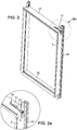
Figure 2 shows the interior window sash and the bolt of the window ofFigure 1 , andFigure 2a shows detail IIa ofFigure 2 . -
Figure 3 shows the exploded view of the window sash ofFigure 2 . -
Figure 4 shows an enlarged view of the bolt of the first embodiment. -
Figure 5 shows the bolt rod of the bolt ofFigure 4 . -
Figure 6, 7 and8 show the bolt rod and bolt seat of theembodiment 1, during the assembly process. -
Figure 9 shows the bolt seat in a second embodiment. -
Figure 10 shows an exploded view of a bolt according to third embodiment. -
Figure 11 shows the bolt seat of the bolt ofFigure 10 . -
Figure 12 shows the bolt ofFigure 10 , assembled. - Three embodiments of the invention will be further described with reference to the figures.
- As shown in
figure 1 to 3 , a window with a bolt of theembodiment 1 contains aninterior window sash 5, abolt 10 arranged on theinterior window sash 5 andexterior window frame 6, wherein theinterior window sash 5 consists of twoerect window frames 53 arranged longitudinally, a upperhorizontal frame 51 and a lowerhorizontal frame 52 arranged horizontally, a secured plugging means 61 for thebolt 10 is arranged on the inner wall of theexterior window frame 6, and thebolt 10 contains abolt rod 1 and abolt seat 2, and anotch 511 for holding thebolt rod 1 is formed on the upperhorizontal frame 51, and thebolt seat 2 is arranged at the level of the end of thenotch 511, and thebolt rod 1 is able to move back and forth on thebolt seat 2. - As shown in
figure 4 and 5 , thebolt seat 2 has the shape of a long strip, and its back end has ascrew hole 21 which is used to make ascrew 30 to be fixed on the upper side of the upperhorizontal frame 51, and its front end has toothed orbarbed parts 4 which can be fixed against the lateral side of the upperhorizontal frame 51, and its middle part is near thescrew hole 21 and has aguide slot 22 along the direction of its length. Two sides of the front end of saidbolt seat 2 are folded downwards respectively so as to formside walls 3, and thetoothed parts 4 projects from the lower side of saidside walls 3 and are in the same plane of the latter. One end of thebolt rod 1 is able to head out of theinterior window sash 5 so that it can cooperate with the secured plugging means 61 of the external window frame in order to establish the connection between theinterior window sash 5 and theexternal window frame 6, while the other end has a projectingactuation button 11 which projects through theguide slot 22 and is able to move back and forth in theguide slot 22. The upper side of thebolt rod 1 has projectingfriction blocks 12, and during the back and forth movement of thebolt rod 1, there is a friction contact between thefriction blocks 12 and thebolt seat 2. - The
actuation button 11 has a width along the length of the bolt rod and has a length perpendicular to the length of said bolt rod, wherein the length of theguide slot 22 is between the width and length of theactuation button 11, and when theactuation button 11 projects through theguide slot 22 and thebolt rob 1 is rotated to the position which is parallel to thebolt seat 2, theactuation button 11 cannot be separated from theguide slot 22 perpendicularly due to the fact that the width of theguide slot 22 is smaller than the length of theactuation button 11. The assembly process is shown infigure 6 to 8 . -
Embodiment 2 is similar toembodiment 1 and distinguishes overembodiment 1 only by the fact that the toothed parts 4' are folded substantially in the form of an L at the lower portion of the front end of theside walls 3. More precisely, each toothed part 4' may include a tab which extends outwardly from the front end of thecorresponding side wall 3, the free end of this tab being extended rearward at least one tooth - here twoteeth -
Embodiment 3 is also similar toembodiment 1 and distinguishes overembodiment 1 only by the fact that therod 1 comprises twodetent means detent means complementary detent means 23 provided on saidbolt seat 2". - More precisely, each of said two detent means 13, 14 may be formed by a hole at a side surface of said
rod 1, and said complementary detent means may be formed by alug 24 provided on an inner face of aflexible tongue 23 which is cut out in theside wall 3 of thebolt seat 2". - From the above description, one understands that the following features of the invention are of importance:
- a. A bolt (10) comprising:
- a bolt seat (2, 2', 2") having the shape of a long strip which extends in a longitudinal direction and comprising a rear end part with an attachment part (21) ;
- a sliding bolt rod (1) able to move back and forth relative to said bolt seat ; and
- a protruding actuation button (11) secured to said bolt rod (1) ; characterized in that said bolt seat (2, 2', 2") further comprises a front end part having at least two toothed parts (4; 4');
- b. Each toothed part comprises at least one tooth (40; 41, 42) which projects backwards in said longitudinal direction;
- c. An intermediate part located between said attachment part (21) and said front end part of said bolt seat (2, 2', 2") has a guide slot (22) extending in the longitudinal direction, and wherein said protruding actuation button (11) projects through said guide slot (22) and is able to move back and forth in said guide slot;
- d. Said sliding bolt rod (1) has a front end able to advance forward beyond the front end of said bolt seat (2, 2', 2") when said sliding bolt rod (1) is moved forward and has a rear end on which said actuation button (11) is secured;
- e. Said attachment part (21) is a screw hole intended for being mounted adjacent to a first side (51) of a window sash (5), and wherein said toothed parts (4; 4') are intended for being knocked in a second side (53) of said window sash;
- d. Said protruding actuation button (11) has a width which extends along the longitudinal direction of said bolt rod (1) and has a length which extends perpendicularly to said longitudinal direction, said width of said actuation button (11) being smaller than a width of said guide slot (22), said length of said actuation button (11) being smaller than a length of said guide slot (22) and greater than a width of said guide slot (22) so that said actuation button (11) is impeded to move downwards in a direction perpendicular to said guide slot when said bolt rod (1) is parallel to the longitudinal direction of said bolt seat (2);
- e. An upper side of said bolt rod (1) has projecting friction blocks (12) provided to slide against a lower side surface of said bolt seat (2, 2', 2") during the back and forth movement of said bolt rod;
- f. Two lateral sides of said front end part of said bolt seat (2, 2', 2") are folded downwards to form two substantially plane side walls (3) parallel to each other, each of said toothed parts (4; 4') being formed in a front end of a said side wall;
- g. Each of said toothed parts (4) projects from a lower edge of the side wall (3) and is in the same plane;
- h. Each of said toothed parts (4') is folded to form a substantially L-shaped part located at a lower end of the front end of the side wall (3);
- i. A main part of said substantially L-shaped part (4') is substantially rectangular and extends perpendicularly to said side wall (3), and a second part of said substantially L-shaped part (4') is formed by said at least one tooth (41, 42);
- j. Said rod (1) comprises two detent means (13, 14) longitudinally distant from each other, each of said detent means (13, 14) being adapted to provide a locking function by cooperation with complementary detent means (23) provided on said bolt seat (2");
- k. Each of said two detent means (13, 14) is formed by a hole at a side surface of said rod (1), and said complementary detent means are formed by a lug (24) provided on an inner face of a flexible tongue (23) which is formed by a cut part of a said side wall (3);
- l. A swivelling window assembly may comprise:
- an interior window sash (5) ;
- a bolt (10) according to any of the preceding numbered features, which is arranged on a first side (51) of said interior window sash (5), the two toothed parts (4; 4') of the bolt seat (2, 2', 2") being secured against a second side (53) of said interior window sash (5) ; and
- an exterior window frame (6) having an inside lateral wall on which are secured plugging means (61) adapted to receive a front end of said bolt.
- m. Said first side (51) of said interior window sash (5) has a groove (511) accommodating said bolt rod (1), while said bolt seat (2, 2', 2") is arranged flush with the opening of said groove.
Claims (8)
- A window bolt (10) comprising a bolt rod (1) and a bolt seat (2; 2'; 2"), wherein
said bolt seat is designed to be arranged on a window frame (5) and said bolt rod is able to move back and forth on said bolt seat (2; 2'; 2"),
one end of said bolt rod (1) being able to head out of said window frame (5) so that it cooperates with the jack or slot of another window frame (6) in order to establish a connection between these two window frames (5, 6), wherein
said bolt seat (2; 2'; 2") is in the form of a long strip shape extending along a longitudinal direction, its back end has fixing means (21) for fixing to a first side (51) of the window frame (5), and its front end has two sides folded downwards respectively in order to form a baffle part (3), said front end further has a toothed part (4, 4') which is adapted to be fixed against a second side (53) of an window frame (5), the toothed part (4, 4') projecting backward in the longitudinal direction and is formed in front of said front end of said baffle part (3), and wherein
the middle part of the bolt seat has a guide hole (22) along the direction of its length, and another end of said bolt rod (1) has a projecting actuation part (11) which projects through said guide hole (22) and is able to move back and forth in said guide hole (22). - A window bolt (10) according to claim 1, wherein
said fixing means (21) are in the form of a screw hole which is used to fix a screw on the first side (51) of said window frame (5). - A window bolt (10) according to claim 1, characterized in that
said actuation part (11) has a width along the length of said bolt rod (1) and has a length perpendicular to the length of said bolt rod (1), wherein the length of said guide hole (22) is between said width and length of said actuation part (11), and when said actuation part (11) projects through said guide hole (22) and said bolt rod (1) is rotated to the position which is parallel to said bolt seat (2; 2'; 2"), said actuation part (11) can not be separated from said guide hole (22) perpendicularly due to the fact that the width of said guide hole is smaller than the length of said actuation part (11). - A window bolt (10) according to any one of the preceding claims, characterized in that
the upper side of said bolt rod (1) has projecting friction blocks (12), and during the back and forth movement of said bolt rod (1), there is a friction contact between said friction blocks (12) and the lower side of said bolt seat (2; 2'; 2"). - A window bolt (10) according to claim 1, characterized in that,- said toothed part (4) projects from the lower side of said baffle part (3) and is in the same plane of the latter, or- said toothed part (4') is folded substantially in the form of an L at the lower and front of said baffle part (3).
- A window bolt (10) according to any one of the preceding claims, wherein
said rod (1) comprises two detent means (13, 14) longitudinally distant from each other, each of said detent means (13, 14) being adapted to provide a locking function by cooperation with complementary detent means (23) provided on said bolt seat (2"). - A window bolt according to claim 6, wherein
each of said two detent means (13, 14) is formed by a hole at a side surface of said rod (1), and said complementary detent means are formed by a lug (24) provided on an inner face of a flexible tongue (23) which is formed by a cut part of a said side wall (3). - A window with a bolt (10) according to anyone of the preceding claims, said window comprising an interior window frame (5) and an exterior window frame (6), wherein:- the inside lateral wall of said exterior window frame (6) has a jack or slot for receiving said bolt (10), the bolt seat (2; 2'; 2") being arranged on said interior window frame (5) and said bolt rod (1) is able to move back and forth on said bolt seat (2; 2'; 2"), one end of said bolt rod (1) is able to head out of said interior window frame (5) so that it cooperates with the jack or slot of said exterior window frame (6) in order to establish the connection between said interior window frame (5) and said exterior window frame (6),- the bolt seat (2; 2'; 2") is fixed to a first side of the inside window frame (5) through said fixing means (21), and the toothed part (4, 4') of the bolt seat (2; 2'; 2") is fixed against a second side of an window frame (5).
Applications Claiming Priority (1)
| Application Number | Priority Date | Filing Date | Title |
|---|---|---|---|
| CN2009201225191U CN201460534U (en) | 2009-06-15 | 2009-06-15 | Window bolt and window utilizing same |
Publications (3)
| Publication Number | Publication Date |
|---|---|
| EP2275629A2 EP2275629A2 (en) | 2011-01-19 |
| EP2275629A3 EP2275629A3 (en) | 2013-12-04 |
| EP2275629B1 true EP2275629B1 (en) | 2017-08-16 |
Family
ID=42387888
Family Applications (1)
| Application Number | Title | Priority Date | Filing Date |
|---|---|---|---|
| EP09180714.9A Not-in-force EP2275629B1 (en) | 2009-06-15 | 2009-12-23 | Window bolt and window therewith |
Country Status (2)
| Country | Link |
|---|---|
| EP (1) | EP2275629B1 (en) |
| CN (1) | CN201460534U (en) |
Families Citing this family (3)
| Publication number | Priority date | Publication date | Assignee | Title |
|---|---|---|---|---|
| CN102877697B (en) * | 2012-10-24 | 2016-02-17 | 温尚武 | The syndeton of a kind of lock and locking bar |
| CN113622765B (en) * | 2021-09-06 | 2022-11-01 | 重庆公共运输职业学院 | Bolt capable of being rapidly installed by utilizing magnetic force without trace |
| US20240309683A1 (en) * | 2023-03-16 | 2024-09-19 | Carolyn Ann Grim | Fence Side Access Gate Latch |
Family Cites Families (9)
| Publication number | Priority date | Publication date | Assignee | Title |
|---|---|---|---|---|
| FR338994A (en) * | 1903-08-21 | 1904-10-18 | Louis Eugene Boyer | Notch lock arrangement for apartment doors, etc. |
| US1409152A (en) * | 1920-07-06 | 1922-03-14 | James T Collins | Door securer |
| GB172459A (en) * | 1920-09-30 | 1921-12-15 | Smith & Davis Ltd | Improvements in sliding bolts for securing wire blinds, and for doors and for other like uses |
| FR1014174A (en) * | 1949-01-18 | 1952-08-11 | Door latch | |
| GB855651A (en) * | 1958-07-15 | 1960-12-07 | Turner & Smith Brassfounders L | Improvements in or relating to door bolts |
| CN2081413U (en) | 1990-10-09 | 1991-07-24 | 姜红梅 | Door and window bolt |
| CN1067474A (en) | 1992-02-17 | 1992-12-30 | 段昭军 | Automatic safe bolt for doors and windows |
| US7976077B2 (en) * | 2005-07-28 | 2011-07-12 | Newell Operating Company | Integrated tilt/sash lock assembly |
| US7591103B2 (en) * | 2005-12-15 | 2009-09-22 | Milgrad Manufacturing, Inc. | Window sash tilt latch |
-
2009
- 2009-06-15 CN CN2009201225191U patent/CN201460534U/en not_active Expired - Fee Related
- 2009-12-23 EP EP09180714.9A patent/EP2275629B1/en not_active Not-in-force
Non-Patent Citations (1)
| Title |
|---|
| None * |
Also Published As
| Publication number | Publication date |
|---|---|
| CN201460534U (en) | 2010-05-12 |
| EP2275629A3 (en) | 2013-12-04 |
| EP2275629A2 (en) | 2011-01-19 |
Similar Documents
| Publication | Publication Date | Title |
|---|---|---|
| JP3676609B2 (en) | Mounting structure of hanging tool in electric power tool | |
| CN101511228A (en) | Drawer | |
| US7922320B1 (en) | Eyegear with a mountable frame | |
| CN104873012A (en) | Slide Rail And Equipment Mounting Rack | |
| EP2275629A2 (en) | Window bolt and window therewith | |
| US8595979B2 (en) | Vehicle rear door having division bar for guiding movable window | |
| US20080302017A1 (en) | Window Latch | |
| CN206554721U (en) | Doorframe connector and its door of application | |
| JP2011117243A (en) | Louver for building | |
| JP5080423B2 (en) | Reaper | |
| CN210493323U (en) | Position adjusting structure for furniture | |
| JP2018071192A (en) | Joinery | |
| JP4368532B2 (en) | Joinery sliding door lock | |
| CN211692188U (en) | Fixed knot constructs and shutter upper beam bracket | |
| JP4884798B2 (en) | Shutter case for architectural shutter equipment | |
| JP2017179941A (en) | handrail | |
| KR20110009419A (en) | Assembly structure of curtain wall window frame | |
| JP3111290U (en) | Movable strike device | |
| CN210178155U (en) | A hinge structure and furniture hinge | |
| CN222759470U (en) | Installation structure for shower room and shower room | |
| CN219931970U (en) | Multifunctional window pushing assembly | |
| CN223607937U (en) | Shower rod fixing seat with adjusting function | |
| TWM544557U (en) | Drip strip featuring direct fixation function | |
| JPH0613962Y2 (en) | Locking device for front panel of drawer | |
| JP4741972B2 (en) | Latch lock |
Legal Events
| Date | Code | Title | Description |
|---|---|---|---|
| PUAI | Public reference made under article 153(3) epc to a published international application that has entered the european phase |
Free format text: ORIGINAL CODE: 0009012 |
|
| AK | Designated contracting states |
Kind code of ref document: A2 Designated state(s): AT BE BG CH CY CZ DE DK EE ES FI FR GB GR HR HU IE IS IT LI LT LU LV MC MK MT NL NO PL PT RO SE SI SK SM TR |
|
| PUAL | Search report despatched |
Free format text: ORIGINAL CODE: 0009013 |
|
| AK | Designated contracting states |
Kind code of ref document: A3 Designated state(s): AT BE BG CH CY CZ DE DK EE ES FI FR GB GR HR HU IE IS IT LI LT LU LV MC MK MT NL NO PL PT RO SE SI SK SM TR |
|
| RIC1 | Information provided on ipc code assigned before grant |
Ipc: E05C 1/04 20060101AFI20131031BHEP |
|
| 17P | Request for examination filed |
Effective date: 20140604 |
|
| RBV | Designated contracting states (corrected) |
Designated state(s): AT BE BG CH CY CZ DE DK EE ES FI FR GB GR HR HU IE IS IT LI LT LU LV MC MK MT NL NO PL PT RO SE SI SK SM TR |
|
| 17Q | First examination report despatched |
Effective date: 20160630 |
|
| GRAP | Despatch of communication of intention to grant a patent |
Free format text: ORIGINAL CODE: EPIDOSNIGR1 |
|
| STAA | Information on the status of an ep patent application or granted ep patent |
Free format text: STATUS: GRANT OF PATENT IS INTENDED |
|
| INTG | Intention to grant announced |
Effective date: 20170307 |
|
| GRAS | Grant fee paid |
Free format text: ORIGINAL CODE: EPIDOSNIGR3 |
|
| GRAA | (expected) grant |
Free format text: ORIGINAL CODE: 0009210 |
|
| STAA | Information on the status of an ep patent application or granted ep patent |
Free format text: STATUS: THE PATENT HAS BEEN GRANTED |
|
| AK | Designated contracting states |
Kind code of ref document: B1 Designated state(s): AT BE BG CH CY CZ DE DK EE ES FI FR GB GR HR HU IE IS IT LI LT LU LV MC MK MT NL NO PL PT RO SE SI SK SM TR |
|
| REG | Reference to a national code |
Ref country code: GB Ref legal event code: FG4D |
|
| REG | Reference to a national code |
Ref country code: CH Ref legal event code: EP |
|
| REG | Reference to a national code |
Ref country code: IE Ref legal event code: FG4D |
|
| REG | Reference to a national code |
Ref country code: AT Ref legal event code: REF Ref document number: 919202 Country of ref document: AT Kind code of ref document: T Effective date: 20170915 |
|
| REG | Reference to a national code |
Ref country code: DE Ref legal event code: R096 Ref document number: 602009047739 Country of ref document: DE |
|
| REG | Reference to a national code |
Ref country code: NL Ref legal event code: MP Effective date: 20170816 Ref country code: FR Ref legal event code: PLFP Year of fee payment: 9 |
|
| REG | Reference to a national code |
Ref country code: LT Ref legal event code: MG4D |
|
| REG | Reference to a national code |
Ref country code: AT Ref legal event code: MK05 Ref document number: 919202 Country of ref document: AT Kind code of ref document: T Effective date: 20170816 |
|
| PG25 | Lapsed in a contracting state [announced via postgrant information from national office to epo] |
Ref country code: LT Free format text: LAPSE BECAUSE OF FAILURE TO SUBMIT A TRANSLATION OF THE DESCRIPTION OR TO PAY THE FEE WITHIN THE PRESCRIBED TIME-LIMIT Effective date: 20170816 Ref country code: FI Free format text: LAPSE BECAUSE OF FAILURE TO SUBMIT A TRANSLATION OF THE DESCRIPTION OR TO PAY THE FEE WITHIN THE PRESCRIBED TIME-LIMIT Effective date: 20170816 Ref country code: AT Free format text: LAPSE BECAUSE OF FAILURE TO SUBMIT A TRANSLATION OF THE DESCRIPTION OR TO PAY THE FEE WITHIN THE PRESCRIBED TIME-LIMIT Effective date: 20170816 Ref country code: NO Free format text: LAPSE BECAUSE OF FAILURE TO SUBMIT A TRANSLATION OF THE DESCRIPTION OR TO PAY THE FEE WITHIN THE PRESCRIBED TIME-LIMIT Effective date: 20171116 Ref country code: SE Free format text: LAPSE BECAUSE OF FAILURE TO SUBMIT A TRANSLATION OF THE DESCRIPTION OR TO PAY THE FEE WITHIN THE PRESCRIBED TIME-LIMIT Effective date: 20170816 Ref country code: NL Free format text: LAPSE BECAUSE OF FAILURE TO SUBMIT A TRANSLATION OF THE DESCRIPTION OR TO PAY THE FEE WITHIN THE PRESCRIBED TIME-LIMIT Effective date: 20170816 |
|
| PGFP | Annual fee paid to national office [announced via postgrant information from national office to epo] |
Ref country code: FR Payment date: 20171220 Year of fee payment: 9 |
|
| PG25 | Lapsed in a contracting state [announced via postgrant information from national office to epo] |
Ref country code: ES Free format text: LAPSE BECAUSE OF FAILURE TO SUBMIT A TRANSLATION OF THE DESCRIPTION OR TO PAY THE FEE WITHIN THE PRESCRIBED TIME-LIMIT Effective date: 20170816 Ref country code: PL Free format text: LAPSE BECAUSE OF FAILURE TO SUBMIT A TRANSLATION OF THE DESCRIPTION OR TO PAY THE FEE WITHIN THE PRESCRIBED TIME-LIMIT Effective date: 20170816 Ref country code: LV Free format text: LAPSE BECAUSE OF FAILURE TO SUBMIT A TRANSLATION OF THE DESCRIPTION OR TO PAY THE FEE WITHIN THE PRESCRIBED TIME-LIMIT Effective date: 20170816 Ref country code: GR Free format text: LAPSE BECAUSE OF FAILURE TO SUBMIT A TRANSLATION OF THE DESCRIPTION OR TO PAY THE FEE WITHIN THE PRESCRIBED TIME-LIMIT Effective date: 20171117 Ref country code: IS Free format text: LAPSE BECAUSE OF FAILURE TO SUBMIT A TRANSLATION OF THE DESCRIPTION OR TO PAY THE FEE WITHIN THE PRESCRIBED TIME-LIMIT Effective date: 20171216 Ref country code: BG Free format text: LAPSE BECAUSE OF FAILURE TO SUBMIT A TRANSLATION OF THE DESCRIPTION OR TO PAY THE FEE WITHIN THE PRESCRIBED TIME-LIMIT Effective date: 20171116 |
|
| PG25 | Lapsed in a contracting state [announced via postgrant information from national office to epo] |
Ref country code: RO Free format text: LAPSE BECAUSE OF FAILURE TO SUBMIT A TRANSLATION OF THE DESCRIPTION OR TO PAY THE FEE WITHIN THE PRESCRIBED TIME-LIMIT Effective date: 20170816 Ref country code: DK Free format text: LAPSE BECAUSE OF FAILURE TO SUBMIT A TRANSLATION OF THE DESCRIPTION OR TO PAY THE FEE WITHIN THE PRESCRIBED TIME-LIMIT Effective date: 20170816 Ref country code: CZ Free format text: LAPSE BECAUSE OF FAILURE TO SUBMIT A TRANSLATION OF THE DESCRIPTION OR TO PAY THE FEE WITHIN THE PRESCRIBED TIME-LIMIT Effective date: 20170816 |
|
| PGFP | Annual fee paid to national office [announced via postgrant information from national office to epo] |
Ref country code: DE Payment date: 20180111 Year of fee payment: 9 Ref country code: GB Payment date: 20180117 Year of fee payment: 9 |
|
| REG | Reference to a national code |
Ref country code: DE Ref legal event code: R097 Ref document number: 602009047739 Country of ref document: DE |
|
| PG25 | Lapsed in a contracting state [announced via postgrant information from national office to epo] |
Ref country code: IT Free format text: LAPSE BECAUSE OF FAILURE TO SUBMIT A TRANSLATION OF THE DESCRIPTION OR TO PAY THE FEE WITHIN THE PRESCRIBED TIME-LIMIT Effective date: 20170816 Ref country code: EE Free format text: LAPSE BECAUSE OF FAILURE TO SUBMIT A TRANSLATION OF THE DESCRIPTION OR TO PAY THE FEE WITHIN THE PRESCRIBED TIME-LIMIT Effective date: 20170816 Ref country code: SK Free format text: LAPSE BECAUSE OF FAILURE TO SUBMIT A TRANSLATION OF THE DESCRIPTION OR TO PAY THE FEE WITHIN THE PRESCRIBED TIME-LIMIT Effective date: 20170816 Ref country code: SM Free format text: LAPSE BECAUSE OF FAILURE TO SUBMIT A TRANSLATION OF THE DESCRIPTION OR TO PAY THE FEE WITHIN THE PRESCRIBED TIME-LIMIT Effective date: 20170816 |
|
| PLBE | No opposition filed within time limit |
Free format text: ORIGINAL CODE: 0009261 |
|
| STAA | Information on the status of an ep patent application or granted ep patent |
Free format text: STATUS: NO OPPOSITION FILED WITHIN TIME LIMIT |
|
| 26N | No opposition filed |
Effective date: 20180517 |
|
| REG | Reference to a national code |
Ref country code: CH Ref legal event code: PL |
|
| PG25 | Lapsed in a contracting state [announced via postgrant information from national office to epo] |
Ref country code: SI Free format text: LAPSE BECAUSE OF FAILURE TO SUBMIT A TRANSLATION OF THE DESCRIPTION OR TO PAY THE FEE WITHIN THE PRESCRIBED TIME-LIMIT Effective date: 20170816 |
|
| REG | Reference to a national code |
Ref country code: IE Ref legal event code: MM4A |
|
| PG25 | Lapsed in a contracting state [announced via postgrant information from national office to epo] |
Ref country code: MT Free format text: LAPSE BECAUSE OF NON-PAYMENT OF DUE FEES Effective date: 20171223 Ref country code: LU Free format text: LAPSE BECAUSE OF NON-PAYMENT OF DUE FEES Effective date: 20171223 |
|
| REG | Reference to a national code |
Ref country code: BE Ref legal event code: MM Effective date: 20171231 |
|
| PG25 | Lapsed in a contracting state [announced via postgrant information from national office to epo] |
Ref country code: IE Free format text: LAPSE BECAUSE OF NON-PAYMENT OF DUE FEES Effective date: 20171223 |
|
| PG25 | Lapsed in a contracting state [announced via postgrant information from national office to epo] |
Ref country code: LI Free format text: LAPSE BECAUSE OF NON-PAYMENT OF DUE FEES Effective date: 20171231 Ref country code: BE Free format text: LAPSE BECAUSE OF NON-PAYMENT OF DUE FEES Effective date: 20171231 Ref country code: CH Free format text: LAPSE BECAUSE OF NON-PAYMENT OF DUE FEES Effective date: 20171231 |
|
| PG25 | Lapsed in a contracting state [announced via postgrant information from national office to epo] |
Ref country code: MC Free format text: LAPSE BECAUSE OF FAILURE TO SUBMIT A TRANSLATION OF THE DESCRIPTION OR TO PAY THE FEE WITHIN THE PRESCRIBED TIME-LIMIT Effective date: 20170816 Ref country code: HU Free format text: LAPSE BECAUSE OF FAILURE TO SUBMIT A TRANSLATION OF THE DESCRIPTION OR TO PAY THE FEE WITHIN THE PRESCRIBED TIME-LIMIT; INVALID AB INITIO Effective date: 20091223 |
|
| REG | Reference to a national code |
Ref country code: DE Ref legal event code: R119 Ref document number: 602009047739 Country of ref document: DE |
|
| GBPC | Gb: european patent ceased through non-payment of renewal fee |
Effective date: 20181223 |
|
| PG25 | Lapsed in a contracting state [announced via postgrant information from national office to epo] |
Ref country code: FR Free format text: LAPSE BECAUSE OF NON-PAYMENT OF DUE FEES Effective date: 20181231 Ref country code: DE Free format text: LAPSE BECAUSE OF NON-PAYMENT OF DUE FEES Effective date: 20190702 Ref country code: CY Free format text: LAPSE BECAUSE OF NON-PAYMENT OF DUE FEES Effective date: 20170816 |
|
| PG25 | Lapsed in a contracting state [announced via postgrant information from national office to epo] |
Ref country code: MK Free format text: LAPSE BECAUSE OF FAILURE TO SUBMIT A TRANSLATION OF THE DESCRIPTION OR TO PAY THE FEE WITHIN THE PRESCRIBED TIME-LIMIT Effective date: 20170816 |
|
| PG25 | Lapsed in a contracting state [announced via postgrant information from national office to epo] |
Ref country code: GB Free format text: LAPSE BECAUSE OF NON-PAYMENT OF DUE FEES Effective date: 20181223 |
|
| PG25 | Lapsed in a contracting state [announced via postgrant information from national office to epo] |
Ref country code: TR Free format text: LAPSE BECAUSE OF FAILURE TO SUBMIT A TRANSLATION OF THE DESCRIPTION OR TO PAY THE FEE WITHIN THE PRESCRIBED TIME-LIMIT Effective date: 20170816 |
|
| PG25 | Lapsed in a contracting state [announced via postgrant information from national office to epo] |
Ref country code: PT Free format text: LAPSE BECAUSE OF FAILURE TO SUBMIT A TRANSLATION OF THE DESCRIPTION OR TO PAY THE FEE WITHIN THE PRESCRIBED TIME-LIMIT Effective date: 20170816 |
|
| PG25 | Lapsed in a contracting state [announced via postgrant information from national office to epo] |
Ref country code: HR Free format text: LAPSE BECAUSE OF FAILURE TO SUBMIT A TRANSLATION OF THE DESCRIPTION OR TO PAY THE FEE WITHIN THE PRESCRIBED TIME-LIMIT Effective date: 20170816 |