EP2275609B1 - Joint apparatus for connecting a faucet and a water pipe - Google Patents
Joint apparatus for connecting a faucet and a water pipe Download PDFInfo
- Publication number
- EP2275609B1 EP2275609B1 EP10158155.1A EP10158155A EP2275609B1 EP 2275609 B1 EP2275609 B1 EP 2275609B1 EP 10158155 A EP10158155 A EP 10158155A EP 2275609 B1 EP2275609 B1 EP 2275609B1
- Authority
- EP
- European Patent Office
- Prior art keywords
- coupler
- joint
- water pipe
- flange
- connection
- Prior art date
- Legal status (The legal status is an assumption and is not a legal conclusion. Google has not performed a legal analysis and makes no representation as to the accuracy of the status listed.)
- Active
Links
Images


Classifications
-
- E—FIXED CONSTRUCTIONS
- E03—WATER SUPPLY; SEWERAGE
- E03C—DOMESTIC PLUMBING INSTALLATIONS FOR FRESH WATER OR WASTE WATER; SINKS
- E03C1/00—Domestic plumbing installations for fresh water or waste water; Sinks
- E03C1/02—Plumbing installations for fresh water
- E03C1/04—Water-basin installations specially adapted to wash-basins or baths
- E03C1/042—Arrangements on taps for wash-basins or baths for connecting to the wall
-
- E—FIXED CONSTRUCTIONS
- E03—WATER SUPPLY; SEWERAGE
- E03C—DOMESTIC PLUMBING INSTALLATIONS FOR FRESH WATER OR WASTE WATER; SINKS
- E03C1/00—Domestic plumbing installations for fresh water or waste water; Sinks
- E03C1/02—Plumbing installations for fresh water
- E03C1/04—Water-basin installations specially adapted to wash-basins or baths
- E03C1/0403—Connecting the supply lines to the tap body
-
- F—MECHANICAL ENGINEERING; LIGHTING; HEATING; WEAPONS; BLASTING
- F16—ENGINEERING ELEMENTS AND UNITS; GENERAL MEASURES FOR PRODUCING AND MAINTAINING EFFECTIVE FUNCTIONING OF MACHINES OR INSTALLATIONS; THERMAL INSULATION IN GENERAL
- F16L—PIPES; JOINTS OR FITTINGS FOR PIPES; SUPPORTS FOR PIPES, CABLES OR PROTECTIVE TUBING; MEANS FOR THERMAL INSULATION IN GENERAL
- F16L19/00—Joints in which sealing surfaces are pressed together by means of a member, e.g. a swivel nut, screwed on, or into, one of the joint parts
- F16L19/02—Pipe ends provided with collars or flanges, integral with the pipe or not, pressed together by a screwed member
- F16L19/025—Pipe ends provided with collars or flanges, integral with the pipe or not, pressed together by a screwed member the pipe ends having integral collars or flanges
-
- F—MECHANICAL ENGINEERING; LIGHTING; HEATING; WEAPONS; BLASTING
- F16—ENGINEERING ELEMENTS AND UNITS; GENERAL MEASURES FOR PRODUCING AND MAINTAINING EFFECTIVE FUNCTIONING OF MACHINES OR INSTALLATIONS; THERMAL INSULATION IN GENERAL
- F16L—PIPES; JOINTS OR FITTINGS FOR PIPES; SUPPORTS FOR PIPES, CABLES OR PROTECTIVE TUBING; MEANS FOR THERMAL INSULATION IN GENERAL
- F16L27/00—Adjustable joints; Joints allowing movement
- F16L27/02—Universal joints, i.e. with mechanical connection allowing angular movement or adjustment of the axes of the parts in any direction
- F16L27/04—Universal joints, i.e. with mechanical connection allowing angular movement or adjustment of the axes of the parts in any direction with partly-spherical engaging surfaces
Definitions
- the invention relates to a joint apparatus for connecting a faucet and a water pipe.
- a coupler When installing a faucet/mixer to a wall, the faucet body and a water pipe emerging from the wall are connected to each other by using a coupler, by which the water pipe is connected to the faucet body/mixer.
- the purpose of a coupler is to provide a watertight joint between a water pipe and a mixer.
- the joint between a faucet body and a water pipe consists of a coupler, an attachment nut, and possibly an eccentric fitting. These above-mentioned components, in the above-mentioned order, establish a joint or connection.
- a first end of the coupler is threadingly fastened to the faucet body and a second end of the coupler is provided with a flange/bracket, which lies at a right angle relative to the coupler's center axis and which has planar flat surfaces. These surfaces are co-directional with a mid-plane of the flange.
- a liner capable of sealing the joint.
- a wall-mounted mixer model is installed to two water pipe ends, generally at a 150 mm distance from each other, by means of the above-described joints.
- the purpose of eccentric fittings is to correct the spacing error between the ends of water pipes. It is also possible that the ends of water pipes extend to an unequal extent from a wall surface, resulting in a similar installation flaw. The tolerance imposed by a spacing error is generally taken care of by a leeway designed in the context of a joint. On the other hand, the misalignment error resulting from the use of eccentric fittings has not been remedied in any way.
- the joint or connection provided by eccentric fittings of the prior art between a faucet body and a water pipe is forced and inflexible, and so is the connection constructed directly on a water pipe without an eccentric fitting.
- a problem with prior art solutions is the inflexibility of a joint between a water pipe and a mixer and the misalignment error of eccentric fittings, both inducing stress on the joint and the water pipes.
- stresses and strains applied to water pipes in the process of installing a mixer may result in damage to water pipes and a deterioration of the joint tightness.
- Another drawback is the need of a post-tightening procedure, caused by eccentric fittings and performed on the installation, said tightening inflicting even more stress on faucet elbows present inside the structures.
- the invention it is an objective of the invention to mitigate prior art problems in a connection or joint between a water pipe and a faucet body/mixer. According to the invention, this objective is accomplished by a joint apparatus according to the features set forth in claim 1.
- the planar mutually parallel joint surfaces, co-directional with a mid-plane of the outward directed bracket in a coupler of the prior art are at least partially replaced by surfaces different from those mentioned above.
- the attachment nut also has a joint surface of its inward directed bracket shaped in a complementary manner.
- a floatingly mounting connection and a coupler capable of removing stresses inflicted in structures and/or water pipes in the process of installation and post-tightening.
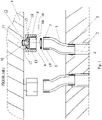
- FIG. 1 Depicted in fig. 1 is a connection or joint of the prior art between a faucet body/mixer 1 and the end of a water pipe 2. To the ends of the water pipes 2 are by threads 3 fastened eccentric fittings 5 at a first end 4 thereof, which fittings are by threads 6 fastened at a second end 7 thereof to an attachment nut 8 provided with complementary threads 9. Between the attachment nut 8 and the faucet body 1 is a coupler 10 of the prior art.
- a first end 11 of the coupler 10 will be by threads 12 attached to the faucet body 1, and a second end 13 of the coupler is provided with an outward directed bracket/flange 15, present at a right angle relative to a center axis 14 of the coupler, and having planar mutually parallel flat surfaces 16 and 17. These surfaces 16 and 17 are co-directional with a mid-plane 18 of the bracket 15. Between the outermost planar surface 16 of the coupler's 10 bracket 15 and the eccentric fitting's 5 second end 7 is a liner 19 capable of sealing the joint.
- fig. 2 Depicted in fig. 2 is a prior art construction for a connection, when the connection between the eccentric fitting 5 and the faucet body 1 is theoretically in alignment.
- the planar surfaces 16 and 17 of the coupler's 10 bracket 15 are co-directional with the surface of the eccentric fitting's 5 second end 7, as well as with a flat surface 21 of the attachment nut's 8 inward directed bracket 20, said surface 21 being perpendicular to the attachment nut's center axis and the coupler's center axis 14 (when the connection or joint is in alignment, the axes are coinciding).
- Figs. 2 and 3 illustrate how to connect the eccentric fitting 5 to the attachment nut 8, but, as previously pointed out, a water pipe can also be fastened directly to an attachment nut without an eccentric fitting.
- All joint surfaces i.e. the surfaces 16 and 17 of the coupler's 10 bracket 15, both surfaces of the attachment nut's inward directed bracket 20, as well as the eccentric fitting's 5 second end 7, are planar surfaces, which planar surfaces are additionally co-directional relative to each other.
- a liner 23 between the coupler 10 and the eccentric fitting's 5 second end 7 is a liner 23.
- fig. 3 Depicted in fig. 3 is a prior art construction for a connection, when the connection between the eccentric fitting 5 and the faucet body 1 is a couple degrees out of alignment. In this case, a center axis 26 of the attachment nut 8 deviates from the coupler's center axis 14.
- the connection or joint is out of alignment, the water pipes and the faucet body 1 will be subjected to extra stresses which may cause damage to the joint, the water pipe, and/or the faucet body. Particularly in installation conducted in old buildings and pipe systems, such stresses and strains applied to water pipes in the process of installing the faucet body 1 may result in damage to water pipes and a deterioration of the joint tightness.
- Another drawback is the need of a post-tightening procedure, caused by eccentric fittings and performed on the installation, said tightening inflicting even more stress on faucet elbows present inside the structures.
- the inflexibility of a joint between the water pipe and the faucet body 1 and the misalignment error of the eccentric fittings 5 induce stress on the joint and the water pipes.
- a coupler 110 has its first end 111 attached by threads 112 to the faucet body 101, and a second end 113 of the coupler is provided with an outward directed flange 115, present with its mid-line 118 at a right angle relative to the coupler's center axis 114.
- the attachment nut 108 fastens the coupler 110 to an eccentric fitting 105 (or optionally directly to a water pipe).
- the coupler 110 of the invention enables the compensation for an installation error without extra stresses on the joint.
- the joint or connection between the eccentric fitting 105 and the faucet body 101, shown in fig. 4 is in a perpendicular position, thus naturally requiring no compensation.
- the coupler 110 of the invention differs from that of the prior art in the sense that the coupler's outward directed flange has its surfaces 116 and 117 shaped in a way different from the prior art solution ( figs. 1-3 ).
- the joint surfaces 116 and 117 of the coupler's 110 flange 115 are conical surfaces or spherical surfaces in an inclined position relative to a mid-plane 118 of the coupler's flange 115 which plane is at a right angle relative to a center ax 114 of the coupler.
- Such a solution provides a swimming/floating (flexible) connection, relieving the connection or joint of stresses resulting from installation errors or the like.
- a ring 124 Between the surface 117 of the coupler's 110 flange 115 and the attachment nut 108 is further fitted a ring 124.
- Fig. 5 shows how the coupler 110 of the invention provides an installation error compensating floating connection between the faucet body 101 and the eccentric fitting 105.
- the eccentric fitting 105 is askew by 2 degrees relative to the coupler's 110 center axis 114 and, at the same time, a center axis 126 of the attachment nut 108 is similarly askew.
- the coupler's 110 inclined surfaces or spherical surfaces 116 and 117 provide a floating joint between the eccentric fitting 105 and the faucet body 101.
- the surfaces 116 and 117 of the coupler's 110 flange 115 are a type of surfaces different from planar surfaces perpendicular to the coupler's center axis, there is accomplished a functional solution of the invention for the joint or connection.
- the surfaces 116 and 117 of the above-described coupler 110 of the invention can be not only spherical surfaces but also other types of arcuate surfaces capable of providing a flexible joint.
- the attachment nut 108 also has its joint surface 125, which is abutting against the surface 117 of the coupler's 110 bracket 115, in the form of an inclined surface, a spherical surface or another type arcuate surface, resulting in a similar effect on the joint.
- the surfaces 116, 117 are respectively shaped as an inclined surface, a spherical surface or another type arcuate surface.
- the mid-line 118 of the coupler's 110 flange 115 need not be in a perpendicular position relative to the coupler's center axis 114, but can be deviated therefrom.
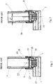
- Fig. 6 shows still another embodiment regarding the shaping of the coupler's 110 flange 115.
- the surface 117 facing an eccentric fitting is slightly inclined, and the surface about to face the attachment nut's joint surface is an arcuate surface.
- the bracket's 115 mid-line becomes arcuate as well.
Landscapes
- Engineering & Computer Science (AREA)
- General Engineering & Computer Science (AREA)
- Health & Medical Sciences (AREA)
- Life Sciences & Earth Sciences (AREA)
- Hydrology & Water Resources (AREA)
- Public Health (AREA)
- Water Supply & Treatment (AREA)
- Mechanical Engineering (AREA)
- Joints Allowing Movement (AREA)
- Domestic Plumbing Installations (AREA)
- Valve Housings (AREA)
Description
- The invention relates to a joint apparatus for connecting a faucet and a water pipe.
- When installing a faucet/mixer to a wall, the faucet body and a water pipe emerging from the wall are connected to each other by using a coupler, by which the water pipe is connected to the faucet body/mixer. The purpose of a coupler is to provide a watertight joint between a water pipe and a mixer.
- The joint between a faucet body and a water pipe consists of a coupler, an attachment nut, and possibly an eccentric fitting. These above-mentioned components, in the above-mentioned order, establish a joint or connection. Thus, a first end of the coupler is threadingly fastened to the faucet body and a second end of the coupler is provided with a flange/bracket, which lies at a right angle relative to the coupler's center axis and which has planar flat surfaces. These surfaces are co-directional with a mid-plane of the flange. Between the outermost planar surface of the coupler's flange and the end of the eccentric fitting/water pipe is a liner capable of sealing the joint.
- A wall-mounted mixer model is installed to two water pipe ends, generally at a 150 mm distance from each other, by means of the above-described joints. When used between the end of a water pipe and the attachment nut, the purpose of eccentric fittings is to correct the spacing error between the ends of water pipes. It is also possible that the ends of water pipes extend to an unequal extent from a wall surface, resulting in a similar installation flaw. The tolerance imposed by a spacing error is generally taken care of by a leeway designed in the context of a joint. On the other hand, the misalignment error resulting from the use of eccentric fittings has not been remedied in any way. The joint or connection provided by eccentric fittings of the prior art between a faucet body and a water pipe is forced and inflexible, and so is the connection constructed directly on a water pipe without an eccentric fitting.
- In the following some prior art solutions are introduced:
- Document
US 6945569 B1 discloses a union for connection two conduits, which is applicable in pressure transmitting hammer unions, which enable two coaxial sections of conduit to be connected without rotating the conduit sections. The solution is based on adjusting the two conduit sections together and locking them together by means of a wing nut. -
Document DE 10 2007 046203 A1 discloses a connecting arrangement wherein the arrangement has a threaded sleeve attached over a borehole in a wall of a hollow body. The sleeve has a sealing seat at its front end turned away from the borehole. A coupling nut is screwable on the sleeve and surrounds a front end of a pipeline connecting the pipeline and the hollow body together. - Document
DE 2031353 A1 , in turn, discloses an connecting arrangement wherein two sections to be connected are mutually directly locked by means of a union nut. - Document
US 4025092 A discloses a solution for directly integrating two sections of fluid carrying conduits by arranging a seat element to one section of conduit. A sleeve element is placed over the seat element and is provided with an interior spherical surface for engagement with the exterior spherical surface of the seat element. An externally threaded union secured to another section of tubint is provided with a thin flexible flange for engagement with the interior spherical surface of the seat element in a stressed relation when engaged by the sleeve element. -
Document DE 10 2006 015652 B3 discloses a fitting to connect a pipe section to a screw connection. The fitting has a cap nut with a spring limit shoulder to press the thickened end of the pipe section durably under spring tension at the sealing seat. The shoulder is in one piece with the cap nut. - Document
DE 19526316 A1 , in turn, discloses a tube connector having a connecting member, a nut, and a tube, wherein the formation cannot be overtightened. To connect the connecting member to the tube, the tube includes a formation with two formation portions. The first formation portion has a first tensioning face which extends parallel to an end face of the connecting member. The second formation portion has a second tensioning face extending in such a way which corresponds to the second conical bore of the nut. - Document
FR 2196053 Document DE 10 2008 053380 discloses a connection of a pipe union with a female connector. The female connector is provided with a thread and a nut is configured to lock the the pipe union with the female connector by means of said threading. - A problem with prior art solutions is the inflexibility of a joint between a water pipe and a mixer and the misalignment error of eccentric fittings, both inducing stress on the joint and the water pipes. Especially in installations conducted in old buildings and pipe systems, such stresses and strains applied to water pipes in the process of installing a mixer may result in damage to water pipes and a deterioration of the joint tightness. Another drawback is the need of a post-tightening procedure, caused by eccentric fittings and performed on the installation, said tightening inflicting even more stress on faucet elbows present inside the structures.
- It is an objective of the invention to mitigate prior art problems in a connection or joint between a water pipe and a faucet body/mixer. According to the invention, this objective is accomplished by a joint apparatus according to the features set forth in
claim 1. In the joint apparatus, the planar mutually parallel joint surfaces, co-directional with a mid-plane of the outward directed bracket in a coupler of the prior art, are at least partially replaced by surfaces different from those mentioned above. According to one preferred embodiment of the invention, the attachment nut also has a joint surface of its inward directed bracket shaped in a complementary manner. According to the invention, there is provided a floatingly mounting connection and a coupler capable of removing stresses inflicted in structures and/or water pipes in the process of installation and post-tightening. - The invention is characterized by what is presented in the characterizing clauses of
independent claim 1. Other preferred embodiments of the invention are disclosed in sub-claims. - The invention will now be described more precisely with reference to the accompanying drawings, in which
-
fig. 1 shows generally a connection between a faucet body/mixer and a water pipe, -
fig. 2 shows a construction of the prior art with the connection theoretically in alignment, -
fig. 3 shows a construction of the prior art with the connection a couple of degrees out of alignment, -
fig. 4 shows a construction of the invention with the connection theoretically in alignment, -
fig. 5 shows a construction of the invention with the connection a couple of degrees out of alignment, and -
fig. 6 shows one embodiment for a coupler's bracket. - Depicted in
fig. 1 is a connection or joint of the prior art between a faucet body/mixer 1 and the end of a water pipe 2. To the ends of the water pipes 2 are by threads 3 fastenedeccentric fittings 5 at afirst end 4 thereof, which fittings are bythreads 6 fastened at asecond end 7 thereof to anattachment nut 8 provided withcomplementary threads 9. Between theattachment nut 8 and thefaucet body 1 is acoupler 10 of the prior art. Hence, afirst end 11 of thecoupler 10 will be bythreads 12 attached to thefaucet body 1, and asecond end 13 of the coupler is provided with an outward directed bracket/flange 15, present at a right angle relative to acenter axis 14 of the coupler, and having planar mutually parallelflat surfaces surfaces bracket 15. Between the outermostplanar surface 16 of the coupler's 10bracket 15 and the eccentric fitting's 5second end 7 is aliner 19 capable of sealing the joint. - Depicted in
fig. 2 is a prior art construction for a connection, when the connection between theeccentric fitting 5 and thefaucet body 1 is theoretically in alignment. In this case, theplanar surfaces bracket 15 are co-directional with the surface of the eccentric fitting's 5second end 7, as well as with aflat surface 21 of the attachment nut's 8 inward directedbracket 20, saidsurface 21 being perpendicular to the attachment nut's center axis and the coupler's center axis 14 (when the connection or joint is in alignment, the axes are coinciding).Figs. 2 and 3 illustrate how to connect theeccentric fitting 5 to theattachment nut 8, but, as previously pointed out, a water pipe can also be fastened directly to an attachment nut without an eccentric fitting. - All joint surfaces, i.e. the
surfaces bracket 15, both surfaces of the attachment nut's inward directedbracket 20, as well as the eccentric fitting's 5second end 7, are planar surfaces, which planar surfaces are additionally co-directional relative to each other. Moreover, between thecoupler 10 and the eccentric fitting's 5second end 7 is aliner 23. When such a prior art construction is theoretically in alignment, as indicated infig. 2 , thecoupler 10 works flawlessly and does not cause problems by stressing the joint or the water pipe. - Depicted in
fig. 3 is a prior art construction for a connection, when the connection between theeccentric fitting 5 and thefaucet body 1 is a couple degrees out of alignment. In this case, acenter axis 26 of theattachment nut 8 deviates from the coupler'scenter axis 14. When the connection or joint is out of alignment, the water pipes and thefaucet body 1 will be subjected to extra stresses which may cause damage to the joint, the water pipe, and/or the faucet body. Particularly in installation conducted in old buildings and pipe systems, such stresses and strains applied to water pipes in the process of installing thefaucet body 1 may result in damage to water pipes and a deterioration of the joint tightness. Another drawback is the need of a post-tightening procedure, caused by eccentric fittings and performed on the installation, said tightening inflicting even more stress on faucet elbows present inside the structures. The inflexibility of a joint between the water pipe and thefaucet body 1 and the misalignment error of theeccentric fittings 5 induce stress on the joint and the water pipes. - Depicted in
fig. 4 is a solution of the invention for a connection or joint between afaucet body 101 and a water pipe. Thus, acoupler 110 has itsfirst end 111 attached bythreads 112 to thefaucet body 101, and asecond end 113 of the coupler is provided with an outward directedflange 115, present with itsmid-line 118 at a right angle relative to the coupler'scenter axis 114. The coupler's 110 flange - 115 attaches to an attachment nut's 108 inward directed
bracket 120 , and between the attachment surfaces is also aring 124. - The
attachment nut 108 fastens thecoupler 110 to an eccentric fitting 105 (or optionally directly to a water pipe). Thecoupler 110 of the invention enables the compensation for an installation error without extra stresses on the joint. The joint or connection between theeccentric fitting 105 and thefaucet body 101, shown infig. 4 , is in a perpendicular position, thus naturally requiring no compensation. Thecoupler 110 of the invention differs from that of the prior art in the sense that the coupler's outward directed flange has itssurfaces figs. 1-3 ). - The
joint surfaces flange 115 are conical surfaces or spherical surfaces in an inclined position relative to amid-plane 118 of the coupler'sflange 115 which plane is at a right angle relative to acenter ax 114 of the coupler. Such a solution provides a swimming/floating (flexible) connection, relieving the connection or joint of stresses resulting from installation errors or the like. Between thesurface 117 of the coupler's 110flange 115 and theattachment nut 108 is further fitted aring 124. -
Fig. 5 shows how thecoupler 110 of the invention provides an installation error compensating floating connection between thefaucet body 101 and theeccentric fitting 105. Infig. 5 , theeccentric fitting 105 is askew by 2 degrees relative to the coupler's 110center axis 114 and, at the same time, acenter axis 126 of theattachment nut 108 is similarly askew. The coupler's 110 inclined surfaces orspherical surfaces eccentric fitting 105 and thefaucet body 101. - By virtue of the
surfaces flange 115, said surfaces being a type of surfaces different from planar surfaces perpendicular to the coupler's center axis, there is accomplished a functional solution of the invention for the joint or connection. Thesurfaces coupler 110 of the invention can be not only spherical surfaces but also other types of arcuate surfaces capable of providing a flexible joint. - The
attachment nut 108 also has itsjoint surface 125, which is abutting against thesurface 117 of the coupler's 110bracket 115, in the form of an inclined surface, a spherical surface or another type arcuate surface, resulting in a similar effect on the joint. - According to the invention, the
surfaces mid-line 118 of the coupler's 110flange 115 need not be in a perpendicular position relative to the coupler'scenter axis 114, but can be deviated therefrom. -
Fig. 6 shows still another embodiment regarding the shaping of the coupler's 110flange 115. In this embodiment, thesurface 117 facing an eccentric fitting is slightly inclined, and the surface about to face the attachment nut's joint surface is an arcuate surface. With the illustrated solution, the bracket's 115 mid-line becomes arcuate as well. - Described above by way of examples are various embodiments of the invention.
- These are by no means limitative but the invention has its scope of protection determined by the scope of protection as defined in the appended claims.
Claims (3)
- A joint apparatus for connecting a faucet and a water pipe, said apparatus comprising- a coupler (110) having threads (112) at its first end (111), the coupler being configured to be attached by the threads (112) to a faucet body (101) and comprising at its second end (113) an outward directed flange (115) having a first surface (116) facing an end of the water pipe and a second surface (117), and- an attachment nut (108) having at its first end threads configured to attach the attachment nut (108) to the water pipe or to an eccentric fitting (105) and comprising at its second end an inward directed bracket (120) configured to fasten the flange (115), said inward directed bracket (120) having a joint surface (125) configured to face the second surface (117) of the outward directed flange (115) of the coupler (110)
characterized in that the joint apparatus further comprising a ring (124) arranged between the second surface (117) of the coupler's (110) flange (115) and the joint surface (125) of the attachment nut's (108) bracket (120), which joint surface (125) is an inclined surface with respect to a plane perpendicular to the attachment nut's (108) center axis (126), and wherein the first surface (116) of the outward directed flange (115) and the second surface (117) of the outward directed flange (115) are inclined with respect to a plane perpendicular to the coupler's center axis, and wherein a shape of the at least one of the following: the first surface (116) of the outward directed flange (115) facing the end of the water pipe, the second surface (117) of the outward directed flange (115) facing the ring (124) is arcuate. - An apparatus according to claim 1, wherein the joint surface (125) is an arcuate surface.
- An apparatus according to any of claims 1-2, further comprising a liner to be placed on the first surface (116) of the coupler's (119) flange (115) configured to seal the joint with the water pipe or the eccentric fitting (105).
Applications Claiming Priority (1)
| Application Number | Priority Date | Filing Date | Title |
|---|---|---|---|
| FI20095364A FI122148B (en) | 2009-04-03 | 2009-04-03 | Connection that compensates for an installation error |
Publications (2)
| Publication Number | Publication Date |
|---|---|
| EP2275609A1 EP2275609A1 (en) | 2011-01-19 |
| EP2275609B1 true EP2275609B1 (en) | 2022-05-11 |
Family
ID=40590247
Family Applications (1)
| Application Number | Title | Priority Date | Filing Date |
|---|---|---|---|
| EP10158155.1A Active EP2275609B1 (en) | 2009-04-03 | 2010-03-29 | Joint apparatus for connecting a faucet and a water pipe |
Country Status (2)
| Country | Link |
|---|---|
| EP (1) | EP2275609B1 (en) |
| FI (1) | FI122148B (en) |
Families Citing this family (2)
| Publication number | Priority date | Publication date | Assignee | Title |
|---|---|---|---|---|
| WO2009121410A1 (en) * | 2008-04-03 | 2009-10-08 | Agilent Technologies, Inc. | Fluidic device with planar coupling member |
| CN104154355A (en) * | 2014-07-31 | 2014-11-19 | 何祺晃 | Convenient-to-mount tap braided hose |
Family Cites Families (9)
| Publication number | Priority date | Publication date | Assignee | Title |
|---|---|---|---|---|
| AU6395265A (en) * | 1965-09-14 | 1967-03-16 | Walker Crosweller & Company Limited | Improvements in, or relating to pipe unions |
| DE2031353A1 (en) * | 1970-06-25 | 1971-12-30 | Heimeier Gmbh Metall Theodor | Welding nipple |
| FR2196053A5 (en) * | 1972-08-09 | 1974-03-08 | Atub Sa Henry D Mesny | |
| US4025092A (en) * | 1973-08-20 | 1977-05-24 | Grumman Aerospace Corporation | Self-aligning detachable fitting |
| DE19526316C3 (en) * | 1995-07-19 | 2002-03-07 | Walterscheid Gmbh Jean | pipe connection |
| US6945569B1 (en) * | 2004-04-28 | 2005-09-20 | S.P.M. Flow Control, Inc. | Enhanced durability hammer union |
| DE102006015652B3 (en) * | 2006-04-04 | 2007-07-19 | Winkelmann Powertrain Components Gmbh & Co. Kg | Fitting to connect a pipe section at a screw connection, in a motor fuel line, has a cap nut with a spring shoulder to press the thickened pipe end against a sealing seat under spring tension |
| DE102007046203A1 (en) * | 2007-09-27 | 2008-05-15 | Audi Ag | Connecting arrangement for connecting front ends of pipe line to distributor of fuel or hydraulic system, has nut pressing during tightening against pressing surface, where sealing surface and pressing surface have center of curvature |
| DE102008053380A1 (en) * | 2007-11-15 | 2009-05-20 | Luk Lamellen Und Kupplungsbau Beteiligungs Kg | Connection of junctions of line with connection socket within hydraulic distance for clutch disengagement and brake systems, has common line axis and line axis includes junction in connection socket |
-
2009
- 2009-04-03 FI FI20095364A patent/FI122148B/en active IP Right Grant
-
2010
- 2010-03-29 EP EP10158155.1A patent/EP2275609B1/en active Active
Also Published As
| Publication number | Publication date |
|---|---|
| FI122148B (en) | 2011-09-15 |
| EP2275609A1 (en) | 2011-01-19 |
| FI20095364A0 (en) | 2009-04-03 |
Similar Documents
| Publication | Publication Date | Title |
|---|---|---|
| US3931992A (en) | Universal joint connector | |
| US4154466A (en) | Pipe section and coupling | |
| CN106415104B (en) | Flange joint reinforcement jig | |
| JP5915918B2 (en) | High pressure pipe joints and joint structures | |
| CN203979698U (en) | A kind of pipe coupling | |
| MX2011004118A (en) | Pipe joint. | |
| AU731517B2 (en) | System for measuring differential pressure, flow, and level | |
| CN201335221Y (en) | Socket-joint pipe connection component provided with wedge-shaped fastening pipe sleeve | |
| KR20080093218A (en) | Height adjustment pipe member for sprinkler head | |
| JPS5810636B2 (en) | Fittings for attaching branch pipes to the main pipe | |
| US11255470B2 (en) | Heavy duty wing nut | |
| US10704721B2 (en) | Coupler assembly that compensates for misalignment | |
| USRE31123E (en) | Pipe section and coupling | |
| EP2275609A1 (en) | Pipe coupler | |
| WO2011133375A1 (en) | Replacement fitting and method of installing same | |
| US20190093800A1 (en) | Tube coupling assembly | |
| KR100831560B1 (en) | Pipe fittings | |
| CN210069197U (en) | Cutting ferrule type hydraulic pipe joint | |
| EP1208271B1 (en) | Connection for a water meter | |
| KR20210063283A (en) | Connection structure of union for piping pipe | |
| CN208487300U (en) | A kind of union elbow component | |
| KR20100007162U (en) | a coupling device of union | |
| KR100385348B1 (en) | Piping system for sprinkler head | |
| KR200325067Y1 (en) | Complex union ring joint value | |
| EP0274548B1 (en) | Coupling device for instruments in pipelines |
Legal Events
| Date | Code | Title | Description |
|---|---|---|---|
| PUAI | Public reference made under article 153(3) epc to a published international application that has entered the european phase |
Free format text: ORIGINAL CODE: 0009012 |
|
| AK | Designated contracting states |
Kind code of ref document: A1 Designated state(s): AT BE BG CH CY CZ DE DK EE ES FI FR GB GR HR HU IE IS IT LI LT LU LV MC MK MT NL NO PL PT RO SE SI SK SM TR |
|
| 17P | Request for examination filed |
Effective date: 20110719 |
|
| 17Q | First examination report despatched |
Effective date: 20111219 |
|
| STAA | Information on the status of an ep patent application or granted ep patent |
Free format text: STATUS: EXAMINATION IS IN PROGRESS |
|
| APBK | Appeal reference recorded |
Free format text: ORIGINAL CODE: EPIDOSNREFNE |
|
| APBN | Date of receipt of notice of appeal recorded |
Free format text: ORIGINAL CODE: EPIDOSNNOA2E |
|
| APBR | Date of receipt of statement of grounds of appeal recorded |
Free format text: ORIGINAL CODE: EPIDOSNNOA3E |
|
| APAF | Appeal reference modified |
Free format text: ORIGINAL CODE: EPIDOSCREFNE |
|
| APBX | Invitation to file observations in appeal sent |
Free format text: ORIGINAL CODE: EPIDOSNOBA2E |
|
| APBZ | Receipt of observations in appeal recorded |
Free format text: ORIGINAL CODE: EPIDOSNOBA4E |
|
| APBT | Appeal procedure closed |
Free format text: ORIGINAL CODE: EPIDOSNNOA9E |
|
| GRAP | Despatch of communication of intention to grant a patent |
Free format text: ORIGINAL CODE: EPIDOSNIGR1 |
|
| STAA | Information on the status of an ep patent application or granted ep patent |
Free format text: STATUS: GRANT OF PATENT IS INTENDED |
|
| INTG | Intention to grant announced |
Effective date: 20211221 |
|
| GRAS | Grant fee paid |
Free format text: ORIGINAL CODE: EPIDOSNIGR3 |
|
| GRAA | (expected) grant |
Free format text: ORIGINAL CODE: 0009210 |
|
| STAA | Information on the status of an ep patent application or granted ep patent |
Free format text: STATUS: THE PATENT HAS BEEN GRANTED |
|
| AK | Designated contracting states |
Kind code of ref document: B1 Designated state(s): AT BE BG CH CY CZ DE DK EE ES FI FR GB GR HR HU IE IS IT LI LT LU LV MC MK MT NL NO PL PT RO SE SI SK SM TR |
|
| REG | Reference to a national code |
Ref country code: GB Ref legal event code: FG4D |
|
| REG | Reference to a national code |
Ref country code: CH Ref legal event code: EP |
|
| REG | Reference to a national code |
Ref country code: AT Ref legal event code: REF Ref document number: 1491524 Country of ref document: AT Kind code of ref document: T Effective date: 20220515 |
|
| REG | Reference to a national code |
Ref country code: DE Ref legal event code: R096 Ref document number: 602010068247 Country of ref document: DE |
|
| REG | Reference to a national code |
Ref country code: IE Ref legal event code: FG4D |
|
| REG | Reference to a national code |
Ref country code: SE Ref legal event code: TRGR |
|
| REG | Reference to a national code |
Ref country code: FI Ref legal event code: FGE |
|
| REG | Reference to a national code |
Ref country code: LT Ref legal event code: MG9D |
|
| REG | Reference to a national code |
Ref country code: NL Ref legal event code: MP Effective date: 20220511 |
|
| PG25 | Lapsed in a contracting state [announced via postgrant information from national office to epo] |
Ref country code: PT Free format text: LAPSE BECAUSE OF FAILURE TO SUBMIT A TRANSLATION OF THE DESCRIPTION OR TO PAY THE FEE WITHIN THE PRESCRIBED TIME-LIMIT Effective date: 20220912 Ref country code: NO Free format text: LAPSE BECAUSE OF FAILURE TO SUBMIT A TRANSLATION OF THE DESCRIPTION OR TO PAY THE FEE WITHIN THE PRESCRIBED TIME-LIMIT Effective date: 20220811 Ref country code: NL Free format text: LAPSE BECAUSE OF FAILURE TO SUBMIT A TRANSLATION OF THE DESCRIPTION OR TO PAY THE FEE WITHIN THE PRESCRIBED TIME-LIMIT Effective date: 20220511 Ref country code: LT Free format text: LAPSE BECAUSE OF FAILURE TO SUBMIT A TRANSLATION OF THE DESCRIPTION OR TO PAY THE FEE WITHIN THE PRESCRIBED TIME-LIMIT Effective date: 20220511 Ref country code: HR Free format text: LAPSE BECAUSE OF FAILURE TO SUBMIT A TRANSLATION OF THE DESCRIPTION OR TO PAY THE FEE WITHIN THE PRESCRIBED TIME-LIMIT Effective date: 20220511 Ref country code: GR Free format text: LAPSE BECAUSE OF FAILURE TO SUBMIT A TRANSLATION OF THE DESCRIPTION OR TO PAY THE FEE WITHIN THE PRESCRIBED TIME-LIMIT Effective date: 20220812 Ref country code: ES Free format text: LAPSE BECAUSE OF FAILURE TO SUBMIT A TRANSLATION OF THE DESCRIPTION OR TO PAY THE FEE WITHIN THE PRESCRIBED TIME-LIMIT Effective date: 20220511 Ref country code: BG Free format text: LAPSE BECAUSE OF FAILURE TO SUBMIT A TRANSLATION OF THE DESCRIPTION OR TO PAY THE FEE WITHIN THE PRESCRIBED TIME-LIMIT Effective date: 20220811 |
|
| PG25 | Lapsed in a contracting state [announced via postgrant information from national office to epo] |
Ref country code: PL Free format text: LAPSE BECAUSE OF FAILURE TO SUBMIT A TRANSLATION OF THE DESCRIPTION OR TO PAY THE FEE WITHIN THE PRESCRIBED TIME-LIMIT Effective date: 20220511 Ref country code: LV Free format text: LAPSE BECAUSE OF FAILURE TO SUBMIT A TRANSLATION OF THE DESCRIPTION OR TO PAY THE FEE WITHIN THE PRESCRIBED TIME-LIMIT Effective date: 20220511 Ref country code: IS Free format text: LAPSE BECAUSE OF FAILURE TO SUBMIT A TRANSLATION OF THE DESCRIPTION OR TO PAY THE FEE WITHIN THE PRESCRIBED TIME-LIMIT Effective date: 20220911 |
|
| PG25 | Lapsed in a contracting state [announced via postgrant information from national office to epo] |
Ref country code: SM Free format text: LAPSE BECAUSE OF FAILURE TO SUBMIT A TRANSLATION OF THE DESCRIPTION OR TO PAY THE FEE WITHIN THE PRESCRIBED TIME-LIMIT Effective date: 20220511 Ref country code: SK Free format text: LAPSE BECAUSE OF FAILURE TO SUBMIT A TRANSLATION OF THE DESCRIPTION OR TO PAY THE FEE WITHIN THE PRESCRIBED TIME-LIMIT Effective date: 20220511 Ref country code: RO Free format text: LAPSE BECAUSE OF FAILURE TO SUBMIT A TRANSLATION OF THE DESCRIPTION OR TO PAY THE FEE WITHIN THE PRESCRIBED TIME-LIMIT Effective date: 20220511 Ref country code: EE Free format text: LAPSE BECAUSE OF FAILURE TO SUBMIT A TRANSLATION OF THE DESCRIPTION OR TO PAY THE FEE WITHIN THE PRESCRIBED TIME-LIMIT Effective date: 20220511 Ref country code: DK Free format text: LAPSE BECAUSE OF FAILURE TO SUBMIT A TRANSLATION OF THE DESCRIPTION OR TO PAY THE FEE WITHIN THE PRESCRIBED TIME-LIMIT Effective date: 20220511 Ref country code: CZ Free format text: LAPSE BECAUSE OF FAILURE TO SUBMIT A TRANSLATION OF THE DESCRIPTION OR TO PAY THE FEE WITHIN THE PRESCRIBED TIME-LIMIT Effective date: 20220511 |
|
| REG | Reference to a national code |
Ref country code: DE Ref legal event code: R097 Ref document number: 602010068247 Country of ref document: DE |
|
| PLBE | No opposition filed within time limit |
Free format text: ORIGINAL CODE: 0009261 |
|
| STAA | Information on the status of an ep patent application or granted ep patent |
Free format text: STATUS: NO OPPOSITION FILED WITHIN TIME LIMIT |
|
| 26N | No opposition filed |
Effective date: 20230214 |
|
| PG25 | Lapsed in a contracting state [announced via postgrant information from national office to epo] |
Ref country code: SI Free format text: LAPSE BECAUSE OF FAILURE TO SUBMIT A TRANSLATION OF THE DESCRIPTION OR TO PAY THE FEE WITHIN THE PRESCRIBED TIME-LIMIT Effective date: 20220511 |
|
| P01 | Opt-out of the competence of the unified patent court (upc) registered |
Effective date: 20230512 |
|
| REG | Reference to a national code |
Ref country code: AT Ref legal event code: UEP Ref document number: 1491524 Country of ref document: AT Kind code of ref document: T Effective date: 20220511 |
|
| PG25 | Lapsed in a contracting state [announced via postgrant information from national office to epo] |
Ref country code: MC Free format text: LAPSE BECAUSE OF FAILURE TO SUBMIT A TRANSLATION OF THE DESCRIPTION OR TO PAY THE FEE WITHIN THE PRESCRIBED TIME-LIMIT Effective date: 20220511 |
|
| REG | Reference to a national code |
Ref country code: CH Ref legal event code: PL |
|
| GBPC | Gb: european patent ceased through non-payment of renewal fee |
Effective date: 20230329 |
|
| REG | Reference to a national code |
Ref country code: BE Ref legal event code: MM Effective date: 20230331 |
|
| PG25 | Lapsed in a contracting state [announced via postgrant information from national office to epo] |
Ref country code: LU Free format text: LAPSE BECAUSE OF NON-PAYMENT OF DUE FEES Effective date: 20230329 |
|
| REG | Reference to a national code |
Ref country code: IE Ref legal event code: MM4A |
|
| PG25 | Lapsed in a contracting state [announced via postgrant information from national office to epo] |
Ref country code: GB Free format text: LAPSE BECAUSE OF NON-PAYMENT OF DUE FEES Effective date: 20230329 |
|
| PG25 | Lapsed in a contracting state [announced via postgrant information from national office to epo] |
Ref country code: LI Free format text: LAPSE BECAUSE OF NON-PAYMENT OF DUE FEES Effective date: 20230331 Ref country code: IT Free format text: LAPSE BECAUSE OF FAILURE TO SUBMIT A TRANSLATION OF THE DESCRIPTION OR TO PAY THE FEE WITHIN THE PRESCRIBED TIME-LIMIT Effective date: 20220511 Ref country code: IE Free format text: LAPSE BECAUSE OF NON-PAYMENT OF DUE FEES Effective date: 20230329 Ref country code: GB Free format text: LAPSE BECAUSE OF NON-PAYMENT OF DUE FEES Effective date: 20230329 Ref country code: FR Free format text: LAPSE BECAUSE OF NON-PAYMENT OF DUE FEES Effective date: 20230331 Ref country code: CH Free format text: LAPSE BECAUSE OF NON-PAYMENT OF DUE FEES Effective date: 20230331 |
|
| PG25 | Lapsed in a contracting state [announced via postgrant information from national office to epo] |
Ref country code: BE Free format text: LAPSE BECAUSE OF NON-PAYMENT OF DUE FEES Effective date: 20230331 |
|
| PG25 | Lapsed in a contracting state [announced via postgrant information from national office to epo] |
Ref country code: BG Free format text: LAPSE BECAUSE OF FAILURE TO SUBMIT A TRANSLATION OF THE DESCRIPTION OR TO PAY THE FEE WITHIN THE PRESCRIBED TIME-LIMIT Effective date: 20220511 |
|
| PG25 | Lapsed in a contracting state [announced via postgrant information from national office to epo] |
Ref country code: BG Free format text: LAPSE BECAUSE OF FAILURE TO SUBMIT A TRANSLATION OF THE DESCRIPTION OR TO PAY THE FEE WITHIN THE PRESCRIBED TIME-LIMIT Effective date: 20220511 |
|
| PGFP | Annual fee paid to national office [announced via postgrant information from national office to epo] |
Ref country code: SE Payment date: 20250318 Year of fee payment: 16 |
|
| PGFP | Annual fee paid to national office [announced via postgrant information from national office to epo] |
Ref country code: DE Payment date: 20250320 Year of fee payment: 16 |
|
| PGFP | Annual fee paid to national office [announced via postgrant information from national office to epo] |
Ref country code: FI Payment date: 20250320 Year of fee payment: 16 |
|
| PGFP | Annual fee paid to national office [announced via postgrant information from national office to epo] |
Ref country code: AT Payment date: 20250319 Year of fee payment: 16 |
|
| PG25 | Lapsed in a contracting state [announced via postgrant information from national office to epo] |
Ref country code: CY Free format text: LAPSE BECAUSE OF FAILURE TO SUBMIT A TRANSLATION OF THE DESCRIPTION OR TO PAY THE FEE WITHIN THE PRESCRIBED TIME-LIMIT; INVALID AB INITIO Effective date: 20100329 |
|
| PG25 | Lapsed in a contracting state [announced via postgrant information from national office to epo] |
Ref country code: HU Free format text: LAPSE BECAUSE OF FAILURE TO SUBMIT A TRANSLATION OF THE DESCRIPTION OR TO PAY THE FEE WITHIN THE PRESCRIBED TIME-LIMIT; INVALID AB INITIO Effective date: 20100329 |
|
| PG25 | Lapsed in a contracting state [announced via postgrant information from national office to epo] |
Ref country code: TR Free format text: LAPSE BECAUSE OF FAILURE TO SUBMIT A TRANSLATION OF THE DESCRIPTION OR TO PAY THE FEE WITHIN THE PRESCRIBED TIME-LIMIT Effective date: 20220511 |