EP2275345A1 - Berth sleeper system - Google Patents
Berth sleeper system Download PDFInfo
- Publication number
- EP2275345A1 EP2275345A1 EP10150908A EP10150908A EP2275345A1 EP 2275345 A1 EP2275345 A1 EP 2275345A1 EP 10150908 A EP10150908 A EP 10150908A EP 10150908 A EP10150908 A EP 10150908A EP 2275345 A1 EP2275345 A1 EP 2275345A1
- Authority
- EP
- European Patent Office
- Prior art keywords
- seat
- backrest
- platform
- seat base
- platform portion
- Prior art date
- Legal status (The legal status is an assumption and is not a legal conclusion. Google has not performed a legal analysis and makes no representation as to the accuracy of the status listed.)
- Granted
Links
Images



Classifications
-
- B—PERFORMING OPERATIONS; TRANSPORTING
- B64—AIRCRAFT; AVIATION; COSMONAUTICS
- B64D—EQUIPMENT FOR FITTING IN OR TO AIRCRAFT; FLIGHT SUITS; PARACHUTES; ARRANGEMENT OR MOUNTING OF POWER PLANTS OR PROPULSION TRANSMISSIONS IN AIRCRAFT
- B64D11/00—Passenger or crew accommodation; Flight-deck installations not otherwise provided for
- B64D11/06—Arrangements of seats, or adaptations or details specially adapted for aircraft seats
- B64D11/0602—Seat modules, i.e. seat systems including furniture separate from the seat itself
- B64D11/0604—Seat modules, i.e. seat systems including furniture separate from the seat itself including a bed, e.g. cocoon type passenger seat modules
Definitions
- the present patent application relates to berth sleeper systems and, more particularly, to berth sleeper systems for aircraft and the like that are convertible from an upright, sitting configuration to a horizontal, sleeping configuration.
- the seats, as well as the arrangement of seats, on a typical aircraft are configured to provide passengers with a certain amount of personal space while maximizing the total number of passengers that may be accommodated by the overall useable space in the aircraft. Therefore, the seats on a typical commercial aircraft are often closely grouped together and substantially only partially recline.
- the disclosed berth sleeper system may include a platform portion and a seat portion, the seat portion defining an axis of rotation and being rotateable relative to the platform portion about the axis of rotation, wherein the seat portion includes a seat base, a backrest and a recline mechanism, the recline mechanism supporting the seat base and the backrest in an upright configuration and a horizontal configuration, wherein the seat base is substantially co-planar with the platform portion, while the backrest is disposed at an angle relative to the seat base in the upright configuration, and wherein the seat base and the backrest are substantially co-planar with the platform portion in the horizontal configuration.
- the disclosed berth sleeper system may include a substantially flat platform portion and a seat portion positioned adjacent to the platform portion, the seat portion defining an axis of rotation and being rotateable at least about 45 degrees relative to the platform portion about the axis of rotation, wherein the seat portion includes a seat base, a backrest and a recline mechanism, the recline mechanism supporting the seat base and the backrest in an upright configuration and a horizontal configuration, wherein the seat base is substantially co-planar with the platform portion and the backrest is disposed at an angle relative to the seat base in the upright configuration, and wherein the seat base, the backrest and the platform portion define a substantially co-planar and continuous sleeping platform in the horizontal configuration.
- one aspect of the disclosed berth sleeper system may include a seat portion 12 and a platform portion 14.
- the seat portion 12 may rotate relative to the platform portion 14 about an axis A 1 of rotation, which may be an axis parallel with the z-axis ( Fig. 2 ), and may recline from an upright, sitting configuration ( Figs. 1-3 ) to a horizontal, sleeping configuration ( Fig. 4 ) to form a sleeping platform.
- the disclosed berth sleeper system 10 may be positioned in a personal sleeping compartment 16 defined by a wall 18.
- the personal sleeping compartment 16 may be in an aircraft (e.g., a commercial airplane), a train, a ship or an automobile.
- aircraft e.g., a commercial airplane
- train e.g., a train
- ship e.g., a ship
- automobile e.g., a passenger car
- the disclosed berth sleeper system 10 may be used in a variety of applications.
- the platform portion 14 of the disclosed berth sleeper system 10 may be a substantially planer platform, wherein the plane defined by the platform portion 14 may be substantially parallel with the x-y plane ( Fig. 2 ).
- the platform portion 14 may be a substantially flat and horizontal platform.
- the platform portion 14 may be cushioned (e.g., with foam padding and/or springs) and upholstered for comfort, as is well known in the art.
- the platform portion 14 may be positioned relative to the seat portion 12 such that the platform portion 14 is substantially co-planar with the seat base 20 (discussed below) of the seat portion 12.
- the platform portion 14 may be elevated about 20 inches from the sub-structure.
- Exemplary techniques for elevating the platform portion 14 relative to the sub-structure include the use of a support structure (not shown) to raise the platform portion 14 and connecting the platform portion 14 to the wall 18 of the personal sleeping compartment 16.
- the platform portion 14 may have various shapes in top view to accommodate the shape of the personal sleeping compartment 16. Furthermore, the platform portion 14 may be sufficiently elongated along a platform axis A 2 to accommodate a substantial portion of a prone human. For example, the platform portion 14 may have a length (in the direction parallel with the platform axis A 2 ) of about 3 to about 5 feet.
- the seat portion 12 of the berth sleeper system 10 may include a seat base 20, a backrest 22, a support structure 24 and a recline mechanism 26 ( Fig. 5 ).
- the seat portion 12 may additionally include a headrest 28.
- the seat portion 12 may additionally include armrests 30, 32.
- the seat portion 12 may additionally include both the headrest 28 and the armrests 30, 32.
- the seat base 20 and the backrest 22 of the seat portion 12, as well as the optional headrest 28 and the armrests 30, 32 may be cushioned (e.g., with foam padding and/or springs) and upholstered for comfort, as is well known in the art.
- the support structure 24 may be secured to a sub-structure, such as a floor or the ground, and may rotateably support the seat portion 12 relative to the sub-structure such that the seat portion 12 is rotateable relative to the platform portion 14 about the axis A 1 of rotation.
- the seat portion 12 may rotate about 45 degrees relative to the platform portion 14.
- Fig. 4 shows the seat portion 12 aligned with the platform portion 14 (i.e., zero degrees of rotation) and Fig. 1 shows the seat portion 12 rotated about 45 degrees from the platform portion 14.
- the seat portion 12 may rotate 360 degrees about the axis A 1 of rotation. Referring to Fig.
- the support structure 24 may include a base 34 secured to the sub-structure and a mount 36 to which the seat base 20 and the backrest 22 may be secured.
- the mount 36 may be rotateably connected to the base 34 to define a swivel connection therebetween.
- Roller bearings (not shown) or the like may be provided to facilitate low-friction rotation of the mount 36 (and associated components of the seat portion 12) relative to the base 34.
- the recline mechanism 26 may be any mechanism that facilitates movement of the seat base 20 and the backrest 22 from the upright, sitting configuration shown in Figs. 1-3 to the horizontal, sleeping configuration shown in Fig. 4 .
- the recline mechanism 26 may be a mechanical mechanism, an electromechanical mechanism or the like.
- the seat base 20 of the seat portion 12 may be substantially co-planar with the platform portion 14, while the backrest 22 of the seat portion 12 may be disposed at an angle (e.g., about 10 to about 90 degrees) relative to the seat base 20.
- a minimum spacing may be provided between the distal portion 52 of the seat base 20 and the proximal portion 54 of the platform portion 14 to provide legroom therebetween.
- a minimum spacing of about 8 to about 14 inches may be provided between the distal portion 52 of the seat base 20 and the proximal portion 54 of the platform portion 14 when the seat portion 12 is in the upright, sitting configuration.
- both the seat base 20 and the backrest 22 of the seat portion 12 may be substantially co-planar with the platform portion 14. Furthermore, in the horizontal, sleeping configuration, the spacing between the distal portion 52 of the seat base 20 and the proximal portion 54 of the platform portion 14 may be minimized (e.g., at most about 2 inches), thereby providing a substantially continuous sleeping platform comprised of both the platform portion 14 and the seat portion 12.
- a substantially co-planar sleeping platform is desired to improve comfort and, therefore, two planes displaced by up to about 3 inches may still be regarded as "substantially co-planar.”
- the recline mechanism 26 may include an electric motor 38, two drawer slides 40, 42, a linear drive 44 and a roller track 46.
- the top portion 48 ( Fig. 1 ) of the backrest 22 may be moveably connected to the roller track 46 such that the backrest 22 can recline from the upright configuration to the fully reclined configuration by traveling along the roller track 46.
- the seat base for example the rear portion 50 ( Fig. 1 ) of the seat base 20, may be connected to the linear drive 44 such that the linear drive 44 may urge the seat base 20 in the proximal and distal directions (i.e., along axis A 2 ).
- the seat base 20 may be secured to and supported by the drawer slides 40, 42.
- the linear drive 44 may urge the seat base 20 in the distal direction (e.g., along axis A 2 toward the proximal end 54 of the platform portion 14). While the seat base 20 is distally advancing, the backrest 22, which may be hingedly connected to the seat base 20 or independent of the seat base 20, may travel along the roller track 46 until the backrest 22 is substantially co-planar with the seat base 20 and the platform portion 14. Of course, the process may be reversed by reversing the direction of travel of the linear drive 44, thereby returning the seat portion 12 to the upright, sitting configuration.
- the disclosed berth sleeper system 10 may include a seat portion 12 that rotates relative to a platform portion 14 about an axis A 1 of rotation, wherein the seat portion 12 is reclineable such that the seat base 20 and the backrest 22 of the seat portion 12 are aligned and substantially co-planar with the platform portion 14 to form a substantially continuous sleeping platform.
Landscapes
- Engineering & Computer Science (AREA)
- Aviation & Aerospace Engineering (AREA)
- Seats For Vehicles (AREA)
- Chairs For Special Purposes, Such As Reclining Chairs (AREA)
Abstract
Description
- The present patent application relates to berth sleeper systems and, more particularly, to berth sleeper systems for aircraft and the like that are convertible from an upright, sitting configuration to a horizontal, sleeping configuration.
- Commercial airline passengers often wish to sleep during long flights, such as trans-ocean flights. However, the seats, as well as the arrangement of seats, on a typical aircraft are configured to provide passengers with a certain amount of personal space while maximizing the total number of passengers that may be accommodated by the overall useable space in the aircraft. Therefore, the seats on a typical commercial aircraft are often closely grouped together and substantially only partially recline.
- Nonetheless, certain passengers on commercial aircraft may be willing to pay a premium for the ability to sleep on a horizontal platform. Therefore, certain carriers are willing to offer such horizontal sleeping platforms. However, carriers that provide such horizontal sleeping platforms continue to seek ways to do so while minimizing the loss of useable space associated with such sleeping platforms.
- Accordingly, there is a need for a berth sleeper system that can be used on commercial aircraft and that is capable of providing a horizontal sleeping platform.
- In one aspect, the disclosed berth sleeper system may include a platform portion and a seat portion, the seat portion defining an axis of rotation and being rotateable relative to the platform portion about the axis of rotation, wherein the seat portion includes a seat base, a backrest and a recline mechanism, the recline mechanism supporting the seat base and the backrest in an upright configuration and a horizontal configuration, wherein the seat base is substantially co-planar with the platform portion, while the backrest is disposed at an angle relative to the seat base in the upright configuration, and wherein the seat base and the backrest are substantially co-planar with the platform portion in the horizontal configuration.
- In another aspect, the disclosed berth sleeper system may include a substantially flat platform portion and a seat portion positioned adjacent to the platform portion, the seat portion defining an axis of rotation and being rotateable at least about 45 degrees relative to the platform portion about the axis of rotation, wherein the seat portion includes a seat base, a backrest and a recline mechanism, the recline mechanism supporting the seat base and the backrest in an upright configuration and a horizontal configuration, wherein the seat base is substantially co-planar with the platform portion and the backrest is disposed at an angle relative to the seat base in the upright configuration, and wherein the seat base, the backrest and the platform portion define a substantially co-planar and continuous sleeping platform in the horizontal configuration.
- Other aspects of the disclosed berth sleeper system will become apparent from the following description, the accompanying drawings and the appended claims.
-
-
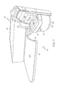
Fig. 1 is a front perspective view of one aspect of the disclosed berth sleeper system, - wherein the seat portion is shown in the upright, sitting configuration;
-
Fig. 2 is a top plan view of the berth sleeper system shown inFig. 1 ; -
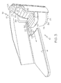
Fig. 3 is a front perspective view of the berth sleeper system ofFig. 1 , wherein the seat portion has been rotated about 45 degrees from the position shown inFig. 1 ; -
Fig. 4 is a front perspective view of the berth sleeper system ofFig. 1 , wherein the seat portion is shown in the horizontal, sleeping configuration; and -
Fig. 5 is a front perspective view of the berth sleeper system ofFig. 1 , wherein the seat portion is partially removed to show the reclining mechanism of the seat portion. - Referring to
Figs. 1 and2 , one aspect of the disclosed berth sleeper system, generally designated 10, may include aseat portion 12 and aplatform portion 14. Theseat portion 12 may rotate relative to theplatform portion 14 about an axis A1 of rotation, which may be an axis parallel with the z-axis (Fig. 2 ), and may recline from an upright, sitting configuration (Figs. 1-3 ) to a horizontal, sleeping configuration (Fig. 4 ) to form a sleeping platform. - In one aspect, the disclosed
berth sleeper system 10 may be positioned in apersonal sleeping compartment 16 defined by awall 18. Thepersonal sleeping compartment 16 may be in an aircraft (e.g., a commercial airplane), a train, a ship or an automobile. However, those skilled in the art will appreciate that the disclosedberth sleeper system 10 may be used in a variety of applications. - Still referring to
Figs. 1 and2 , theplatform portion 14 of the disclosedberth sleeper system 10 may be a substantially planer platform, wherein the plane defined by theplatform portion 14 may be substantially parallel with the x-y plane (Fig. 2 ). For example, theplatform portion 14 may be a substantially flat and horizontal platform. Those skilled in the art will appreciate that theplatform portion 14 may be cushioned (e.g., with foam padding and/or springs) and upholstered for comfort, as is well known in the art. - As shown in
Figs. 1 ,3 and4 , theplatform portion 14 may be positioned relative to theseat portion 12 such that theplatform portion 14 is substantially co-planar with the seat base 20 (discussed below) of theseat portion 12. For example, when theseat base 20 of theseat portion 12 is raised about 20 inches from the sub-structure (not shown) supporting theseat portion 12, theplatform portion 14 may be elevated about 20 inches from the sub-structure. Exemplary techniques for elevating theplatform portion 14 relative to the sub-structure include the use of a support structure (not shown) to raise theplatform portion 14 and connecting theplatform portion 14 to thewall 18 of thepersonal sleeping compartment 16. - Referring to
Fig. 2 , theplatform portion 14 may have various shapes in top view to accommodate the shape of thepersonal sleeping compartment 16. Furthermore, theplatform portion 14 may be sufficiently elongated along a platform axis A2 to accommodate a substantial portion of a prone human. For example, theplatform portion 14 may have a length (in the direction parallel with the platform axis A2) of about 3 to about 5 feet. - Referring again to
Figs. 1 and2 , theseat portion 12 of theberth sleeper system 10 may include aseat base 20, abackrest 22, asupport structure 24 and a recline mechanism 26 (Fig. 5 ). In one optional aspect, theseat portion 12 may additionally include aheadrest 28. In another optional aspect, theseat portion 12 may additionally includearmrests seat portion 12 may additionally include both theheadrest 28 and thearmrests seat base 20 and thebackrest 22 of theseat portion 12, as well as theoptional headrest 28 and thearmrests - The
support structure 24 may be secured to a sub-structure, such as a floor or the ground, and may rotateably support theseat portion 12 relative to the sub-structure such that theseat portion 12 is rotateable relative to theplatform portion 14 about the axis A1 of rotation. In one exemplary aspect, theseat portion 12 may rotate about 45 degrees relative to theplatform portion 14. For example,Fig. 4 shows theseat portion 12 aligned with the platform portion 14 (i.e., zero degrees of rotation) andFig. 1 shows theseat portion 12 rotated about 45 degrees from theplatform portion 14. In another exemplary aspect, theseat portion 12 may rotate 360 degrees about the axis A1 of rotation. Referring toFig. 1 , in one particular aspect, thesupport structure 24 may include abase 34 secured to the sub-structure and amount 36 to which theseat base 20 and thebackrest 22 may be secured. Themount 36 may be rotateably connected to thebase 34 to define a swivel connection therebetween. Roller bearings (not shown) or the like may be provided to facilitate low-friction rotation of the mount 36 (and associated components of the seat portion 12) relative to thebase 34. - The
recline mechanism 26 may be any mechanism that facilitates movement of theseat base 20 and thebackrest 22 from the upright, sitting configuration shown inFigs. 1-3 to the horizontal, sleeping configuration shown inFig. 4 . Those skilled in the art will appreciate that therecline mechanism 26 may be a mechanical mechanism, an electromechanical mechanism or the like. - In the upright, sitting configuration shown in
Figs. 1-3 , theseat base 20 of theseat portion 12 may be substantially co-planar with theplatform portion 14, while thebackrest 22 of theseat portion 12 may be disposed at an angle (e.g., about 10 to about 90 degrees) relative to theseat base 20. In one aspect, as shown inFig. 3 , a minimum spacing may be provided between thedistal portion 52 of theseat base 20 and theproximal portion 54 of theplatform portion 14 to provide legroom therebetween. For example, a minimum spacing of about 8 to about 14 inches may be provided between thedistal portion 52 of theseat base 20 and theproximal portion 54 of theplatform portion 14 when theseat portion 12 is in the upright, sitting configuration. - In the horizontal, sleeping configuration shown in
Fig. 4 , both theseat base 20 and thebackrest 22 of theseat portion 12 may be substantially co-planar with theplatform portion 14. Furthermore, in the horizontal, sleeping configuration, the spacing between thedistal portion 52 of theseat base 20 and theproximal portion 54 of theplatform portion 14 may be minimized (e.g., at most about 2 inches), thereby providing a substantially continuous sleeping platform comprised of both theplatform portion 14 and theseat portion 12. - Referring to
Figs. 1 and2 , those skilled in the art will appreciate that reference to theseat base 20 and thebackrest 22 being substantially co-planar with theplatform portion 14 may optionally refer to theupper surfaces 56, 58 of theseat base 20 and thebackrest 22 being substantially co-planar with theupper surface 60 of theplatform portion 14. Furthermore, those skilled in the art will appreciate that a substantially co-planar sleeping platform is desired to improve comfort and, therefore, two planes displaced by up to about 3 inches may still be regarded as "substantially co-planar." - Referring to
Fig. 5 , in one exemplary aspect, therecline mechanism 26 may include anelectric motor 38, twodrawer slides linear drive 44 and aroller track 46. The top portion 48 (Fig. 1 ) of thebackrest 22 may be moveably connected to theroller track 46 such that thebackrest 22 can recline from the upright configuration to the fully reclined configuration by traveling along theroller track 46. The seat base, for example the rear portion 50 (Fig. 1 ) of theseat base 20, may be connected to thelinear drive 44 such that thelinear drive 44 may urge theseat base 20 in the proximal and distal directions (i.e., along axis A2). Furthermore, theseat base 20 may be secured to and supported by thedrawer slides - Thus, when the
electric motor 38 is actuated, thelinear drive 44 may urge theseat base 20 in the distal direction (e.g., along axis A2 toward theproximal end 54 of the platform portion 14). While theseat base 20 is distally advancing, thebackrest 22, which may be hingedly connected to theseat base 20 or independent of theseat base 20, may travel along theroller track 46 until thebackrest 22 is substantially co-planar with theseat base 20 and theplatform portion 14. Of course, the process may be reversed by reversing the direction of travel of thelinear drive 44, thereby returning theseat portion 12 to the upright, sitting configuration. - Accordingly, the disclosed
berth sleeper system 10 may include aseat portion 12 that rotates relative to aplatform portion 14 about an axis A1 of rotation, wherein theseat portion 12 is reclineable such that theseat base 20 and thebackrest 22 of theseat portion 12 are aligned and substantially co-planar with theplatform portion 14 to form a substantially continuous sleeping platform. - Although various aspects of the disclosed berth sleeper system have been shown and described, modifications may occur to those skilled in the art upon reading the specification. The present application includes such modifications and is limited only by the scope of the claims.
Claims (15)
- A berth sleeper system comprising:a platform portion; anda seat portion, said seat portion defining an axis of rotation and being rotateable relative to said platform portion about said axis of rotation, wherein said seat portion includes a seat base, a backrest and a recline mechanism, said recline mechanism supporting said seat base and said backrest in an upright configuration and a horizontal configuration,wherein said seat base is substantially co-planar with said platform portion, while said backrest is disposed at an angle relative to said seat base in said upright configuration, and wherein said seat base and said backrest are substantially co-planar with said platform portion in said horizontal configuration.
- The berth sleeper system of claim 1 further comprising a wall defining a personal sleeping compartment, wherein said platform portion and said seat portion are positioned in said personal sleeping compartment.
- The berth sleeper system of claim 1 wherein said platform portion includes cushioning.
- The berth sleeper system of claim 1 wherein said platform portion has a length of about 3 to about 5 feet.
- The berth sleeper system of claim 1 wherein said seat portion further includes a headrest.
- The berth sleeper system of claim 1 wherein said seat portion further includes at least one armrest.
- The berth sleeper system of claim 1 wherein said seat portion is rotateable about 45 degrees relative to said platform portion.
- The berth sleeper system of claim 1 wherein said recline mechanism includes a linear drive connected to said seat base.
- The berth sleeper system of claim 8 wherein said recline mechanism further includes an electric motor coupled to said linear drive.
- The berth sleeper system of claim 1 wherein said recline mechanism includes a roller track and said backrest is moveably connected to said roller track.
- The berth sleeper system of claim 1 wherein said seat base, said backrest and said platform portion define a substantially continuous sleeping platform when said seat portion is in said horizontal configuration.
- A berth sleeper system comprising:a substantially flat platform portion; anda seat portion positioned adjacent to said platform portion, said seat portion defining an axis of rotation and being rotateable at least about 45 degrees relative to said platform portion about said axis of rotation, wherein said seat portion includes a seat base, a backrest and a recline mechanism, said recline mechanism supporting said seat base and said backrest in an upright configuration and a horizontal configuration,wherein said seat base is substantially co-planar with said platform portion and said backrest is disposed at an angle relative to said seat base in said upright configuration, and wherein said seat base, said backrest and said platform portion define a substantially co-planar and continuous sleeping platform in said horizontal configuration.
- The berth sleeper system of claim 1 or claim 12 wherein said seat portion further includes a support structure that elevates said seat base from an associated sub-structure, wherein said support structure defines a swivel connection with said sub-structure.
- The berth sleeper system of claim 1 or claim 12 wherein said seat base includes a distal end and said platform portion includes a proximal end, and wherein a distance between said distal end and said proximal end is about 8 to about 14 inches when said seat portion is in said upright configuration and aligned with said platform portion.
- The berth sleeper system of claim 14 wherein said distance is at most about 2 inches when said seat portion is in said horizontal configuration.
Applications Claiming Priority (1)
| Application Number | Priority Date | Filing Date | Title |
|---|---|---|---|
| US12/504,147 US8876202B2 (en) | 2009-07-16 | 2009-07-16 | Berth sleeper system |
Publications (2)
| Publication Number | Publication Date |
|---|---|
| EP2275345A1 true EP2275345A1 (en) | 2011-01-19 |
| EP2275345B1 EP2275345B1 (en) | 2014-03-12 |
Family
ID=42830810
Family Applications (1)
| Application Number | Title | Priority Date | Filing Date |
|---|---|---|---|
| EP10150908.1A Active EP2275345B1 (en) | 2009-07-16 | 2010-01-15 | Berth sleeper system |
Country Status (2)
| Country | Link |
|---|---|
| US (1) | US8876202B2 (en) |
| EP (1) | EP2275345B1 (en) |
Cited By (3)
| Publication number | Priority date | Publication date | Assignee | Title |
|---|---|---|---|---|
| EP2733073A1 (en) * | 2012-10-24 | 2014-05-21 | Recaro Aircraft Seating GmbH & Co. KG | Vehicle seat |
| WO2015155687A1 (en) * | 2014-04-07 | 2015-10-15 | Zodiac Seats France | A seat unit |
| US11577840B2 (en) * | 2019-09-17 | 2023-02-14 | Bombardier Inc. | Aircraft divan |
Families Citing this family (19)
| Publication number | Priority date | Publication date | Assignee | Title |
|---|---|---|---|---|
| FR3004419B1 (en) * | 2013-04-12 | 2016-04-29 | Zodiac Seats France | CABIN ARRANGEMENT BUSINESS CLASS. |
| USD733442S1 (en) * | 2014-03-25 | 2015-07-07 | Acumen Design Associates Limited | Aircraft passenger seating arrangement |
| DE102014110819A1 (en) * | 2014-07-30 | 2016-02-04 | Recaro Aircraft Seating Gmbh & Co. Kg | Aircraft seating system |
| USD758776S1 (en) | 2015-02-13 | 2016-06-14 | Steelcase, Inc. | Personal workspace furniture |
| USD758115S1 (en) | 2015-02-13 | 2016-06-07 | Steelcase, Inc. | Personal workspace furniture |
| USD778653S1 (en) | 2015-02-13 | 2017-02-14 | Steelcase Inc. | Table top |
| US9622570B1 (en) | 2015-02-13 | 2017-04-18 | Steelcase Inc. | Personal workspace assembly |
| USD758777S1 (en) | 2015-02-13 | 2016-06-14 | Steelcase, Inc. | Personal workspace furniture |
| US20190047445A1 (en) * | 2016-09-30 | 2019-02-14 | Faraday&Future Inc. | In-vehicle bed assembly |
| EP3583030B1 (en) | 2017-02-17 | 2022-04-06 | Safran Seats USA LLC | Passenger seat with comfort layout |
| CN110431039B (en) * | 2017-03-17 | 2022-04-01 | 赛峰座椅美国有限责任公司 | Passenger seat with movable backrest part |
| US10384566B2 (en) * | 2017-08-25 | 2019-08-20 | Ford Global Technologies, Llc | Vehicle seat assembly |
| EP3774484B1 (en) | 2018-04-04 | 2023-06-07 | Zephyr Aerospace, LLC | Vehicular seating suite configuration |
| USD917906S1 (en) * | 2019-03-28 | 2021-05-04 | Airbus Interiors Services Sas | Seat arrangement |
| USD911725S1 (en) * | 2019-04-03 | 2021-03-02 | Zephyr Aerospace, LLC | Vehicular seating suite arrangement |
| USD909783S1 (en) * | 2019-04-03 | 2021-02-09 | Zephyr Aerospace, LLC | Vehicular seating suite arrangement |
| USD911726S1 (en) * | 2019-04-03 | 2021-03-02 | Zephyr Aerospace, LLC | Vehicular seating suite arrangement |
| GB2586273B (en) * | 2019-08-16 | 2023-04-12 | Safran Seats Gb Ltd | An aircraft cabin |
| USD994358S1 (en) | 2021-02-02 | 2023-08-08 | Zephyr Aerospace, LLC | Vehicular seating suite |
Citations (2)
| Publication number | Priority date | Publication date | Assignee | Title |
|---|---|---|---|---|
| EP1211176A1 (en) * | 2000-11-30 | 2002-06-05 | Airbus Deutschland GmbH | Passenger seat arrangement in an aircraft cabin |
| WO2008046027A1 (en) * | 2006-10-12 | 2008-04-17 | Be Aerospace, Inc. | Translatable and rotatable passenger seat |
Family Cites Families (20)
| Publication number | Priority date | Publication date | Assignee | Title |
|---|---|---|---|---|
| US1470004A (en) * | 1922-06-07 | 1923-10-09 | Gahm Frank | Vehicle seat |
| US2348407A (en) * | 1940-10-28 | 1944-05-09 | O'neill Ralph Hender | Convertible sleeping unit |
| GB9425078D0 (en) * | 1994-12-13 | 1995-02-08 | British Airways Plc | A seating unit |
| US5790997A (en) * | 1995-08-04 | 1998-08-11 | Hill-Rom Inc. | Table/chair egress device |
| US20010000639A1 (en) * | 1997-02-20 | 2001-05-03 | Singapore Airlines Ltd. | Transport accommodation |
| SG54502A1 (en) * | 1997-02-20 | 1998-11-16 | Singapore Airlines Ltd | Improvements in transport accommodation |
| US5954401A (en) * | 1997-08-30 | 1999-09-21 | Aircraft Modular Products, Inc. | Reclining seat and ottoman system for aircraft including amenity cabinet |
| ES2239461T3 (en) * | 1998-10-15 | 2005-09-16 | British Airways Plc | ONE SEAT UNIT. |
| US6305644B1 (en) * | 1999-11-10 | 2001-10-23 | B E Aerospace, Inc. | Aircraft cabin seat configuration with enhanced ingress/egress |
| FR2818595B1 (en) * | 2000-12-26 | 2003-03-07 | Eads Sogerma | BED CONVERTIBLE ARMCHAIR, ESPECIALLY FOR AIRCRAFT |
| FR2820400B1 (en) * | 2001-02-05 | 2003-04-11 | Sicma Aero Seat | MULTI-POSITION SEAT FOR AIRPLANE |
| US6692069B2 (en) * | 2001-07-20 | 2004-02-17 | B E Aerospace, Inc. | Aircraft sleeper seat |
| US6685267B1 (en) * | 2002-12-19 | 2004-02-03 | L & P Property Management Company | Chair and synchrotilt chair mechanism |
| USD583579S1 (en) * | 2004-06-18 | 2008-12-30 | Virgin Atlantic Airways Limited | Airplane seating unit |
| JP2009504510A (en) * | 2005-08-22 | 2009-02-05 | ビー イー エアロスペイス,インク. | Lounge seat arrangement structure |
| WO2007061381A1 (en) * | 2005-11-24 | 2007-05-31 | Singapore Airlines Limited | Aircraft seating and seating arrangements |
| US7934762B2 (en) * | 2005-12-13 | 2011-05-03 | Mack Trucks, Inc. | Vehicle with sleeping arrangement |
| ATE474772T1 (en) * | 2005-12-23 | 2010-08-15 | British Airways Plc | AIRCRAFT PASSENGER SEAT |
| GB0706775D0 (en) * | 2007-04-05 | 2007-05-16 | Premium Aircraft Interiors Uk | Aircraft seat |
| TWM378690U (en) * | 2009-12-01 | 2010-04-21 | Chi Bo Industry Co Ltd | Machine capable of adjusting gap between seat pad and back cushion |
-
2009
- 2009-07-16 US US12/504,147 patent/US8876202B2/en active Active
-
2010
- 2010-01-15 EP EP10150908.1A patent/EP2275345B1/en active Active
Patent Citations (2)
| Publication number | Priority date | Publication date | Assignee | Title |
|---|---|---|---|---|
| EP1211176A1 (en) * | 2000-11-30 | 2002-06-05 | Airbus Deutschland GmbH | Passenger seat arrangement in an aircraft cabin |
| WO2008046027A1 (en) * | 2006-10-12 | 2008-04-17 | Be Aerospace, Inc. | Translatable and rotatable passenger seat |
Cited By (5)
| Publication number | Priority date | Publication date | Assignee | Title |
|---|---|---|---|---|
| EP2733073A1 (en) * | 2012-10-24 | 2014-05-21 | Recaro Aircraft Seating GmbH & Co. KG | Vehicle seat |
| US9682779B2 (en) | 2012-10-24 | 2017-06-20 | Recaro Aircraft Seating Gmbh & Co. Kg | Vehicle seat |
| WO2015155687A1 (en) * | 2014-04-07 | 2015-10-15 | Zodiac Seats France | A seat unit |
| US10315772B2 (en) | 2014-04-07 | 2019-06-11 | Zodiac Seats France | Seat unit |
| US11577840B2 (en) * | 2019-09-17 | 2023-02-14 | Bombardier Inc. | Aircraft divan |
Also Published As
| Publication number | Publication date |
|---|---|
| EP2275345B1 (en) | 2014-03-12 |
| US8876202B2 (en) | 2014-11-04 |
| US20110011977A1 (en) | 2011-01-20 |
Similar Documents
| Publication | Publication Date | Title |
|---|---|---|
| US8876202B2 (en) | Berth sleeper system | |
| CN103596844B (en) | Flexible-usage travel suite | |
| CN106414240B (en) | Bracket tilt mechanism for aircraft seats with fixed shells | |
| JP5097208B2 (en) | Moving and rotatable passenger seat | |
| EP3122632B1 (en) | Aircraft seat with segmented seatback for achieving in-bed lounge sitting position | |
| CN105916768B (en) | airplane couch that converts into a bed | |
| JP4548421B2 (en) | Vehicle seat that provides sleeping posture | |
| EP2814690B1 (en) | Convertible seating unit | |
| US20170021930A1 (en) | Cradle recline mechanism for aircraft passenger seat | |
| WO2017155069A1 (en) | Seat structure | |
| CA2902891A1 (en) | Aircraft seat employing dual actuators for seat translation and seat recline | |
| CN101808899A (en) | Aircraft passenger seat | |
| CN110506004B (en) | Passenger seat with comfortable layout | |
| WO2014168916A1 (en) | Aircraft seat with translating seatback linkage pivot | |
| CN103857592A (en) | Aircraft divan convertible to a bunk bed | |
| EP2222558A2 (en) | Improvements relating to vehicle seating apparatus | |
| US20090195046A1 (en) | Economy Class Passenger Transportation Seat with Leg Rest | |
| WO2006054104A1 (en) | Seatbed | |
| CN112591103A (en) | Aircraft sofa chair | |
| US20220033082A1 (en) | Aircraft seating with direct aisle access | |
| GB2619723A (en) | Passenger seat assembly for an aircraft | |
| KR20250115226A (en) | Full bed seat |
Legal Events
| Date | Code | Title | Description |
|---|---|---|---|
| PUAI | Public reference made under article 153(3) epc to a published international application that has entered the european phase |
Free format text: ORIGINAL CODE: 0009012 |
|
| 17P | Request for examination filed |
Effective date: 20100125 |
|
| AK | Designated contracting states |
Kind code of ref document: A1 Designated state(s): AT BE BG CH CY CZ DE DK EE ES FI FR GB GR HR HU IE IS IT LI LT LU LV MC MK MT NL NO PL PT RO SE SI SK SM TR |
|
| 17Q | First examination report despatched |
Effective date: 20120515 |
|
| GRAP | Despatch of communication of intention to grant a patent |
Free format text: ORIGINAL CODE: EPIDOSNIGR1 |
|
| GRAP | Despatch of communication of intention to grant a patent |
Free format text: ORIGINAL CODE: EPIDOSNIGR1 |
|
| INTG | Intention to grant announced |
Effective date: 20130909 |
|
| GRAS | Grant fee paid |
Free format text: ORIGINAL CODE: EPIDOSNIGR3 |
|
| GRAA | (expected) grant |
Free format text: ORIGINAL CODE: 0009210 |
|
| AK | Designated contracting states |
Kind code of ref document: B1 Designated state(s): AT BE BG CH CY CZ DE DK EE ES FI FR GB GR HR HU IE IS IT LI LT LU LV MC MK MT NL NO PL PT RO SE SI SK SM TR |
|
| REG | Reference to a national code |
Ref country code: GB Ref legal event code: FG4D |
|
| REG | Reference to a national code |
Ref country code: CH Ref legal event code: EP |
|
| REG | Reference to a national code |
Ref country code: AT Ref legal event code: REF Ref document number: 656108 Country of ref document: AT Kind code of ref document: T Effective date: 20140315 |
|
| REG | Reference to a national code |
Ref country code: IE Ref legal event code: FG4D |
|
| REG | Reference to a national code |
Ref country code: DE Ref legal event code: R096 Ref document number: 602010014119 Country of ref document: DE Effective date: 20140424 |
|
| REG | Reference to a national code |
Ref country code: NL Ref legal event code: VDEP Effective date: 20140312 |
|
| PG25 | Lapsed in a contracting state [announced via postgrant information from national office to epo] |
Ref country code: LT Free format text: LAPSE BECAUSE OF FAILURE TO SUBMIT A TRANSLATION OF THE DESCRIPTION OR TO PAY THE FEE WITHIN THE PRESCRIBED TIME-LIMIT Effective date: 20140312 Ref country code: NO Free format text: LAPSE BECAUSE OF FAILURE TO SUBMIT A TRANSLATION OF THE DESCRIPTION OR TO PAY THE FEE WITHIN THE PRESCRIBED TIME-LIMIT Effective date: 20140612 |
|
| REG | Reference to a national code |
Ref country code: AT Ref legal event code: MK05 Ref document number: 656108 Country of ref document: AT Kind code of ref document: T Effective date: 20140312 |
|
| REG | Reference to a national code |
Ref country code: LT Ref legal event code: MG4D |
|
| PG25 | Lapsed in a contracting state [announced via postgrant information from national office to epo] |
Ref country code: SE Free format text: LAPSE BECAUSE OF FAILURE TO SUBMIT A TRANSLATION OF THE DESCRIPTION OR TO PAY THE FEE WITHIN THE PRESCRIBED TIME-LIMIT Effective date: 20140312 Ref country code: CY Free format text: LAPSE BECAUSE OF FAILURE TO SUBMIT A TRANSLATION OF THE DESCRIPTION OR TO PAY THE FEE WITHIN THE PRESCRIBED TIME-LIMIT Effective date: 20140312 Ref country code: FI Free format text: LAPSE BECAUSE OF FAILURE TO SUBMIT A TRANSLATION OF THE DESCRIPTION OR TO PAY THE FEE WITHIN THE PRESCRIBED TIME-LIMIT Effective date: 20140312 |
|
| PG25 | Lapsed in a contracting state [announced via postgrant information from national office to epo] |
Ref country code: LV Free format text: LAPSE BECAUSE OF FAILURE TO SUBMIT A TRANSLATION OF THE DESCRIPTION OR TO PAY THE FEE WITHIN THE PRESCRIBED TIME-LIMIT Effective date: 20140312 Ref country code: HR Free format text: LAPSE BECAUSE OF FAILURE TO SUBMIT A TRANSLATION OF THE DESCRIPTION OR TO PAY THE FEE WITHIN THE PRESCRIBED TIME-LIMIT Effective date: 20140312 |
|
| PG25 | Lapsed in a contracting state [announced via postgrant information from national office to epo] |
Ref country code: RO Free format text: LAPSE BECAUSE OF FAILURE TO SUBMIT A TRANSLATION OF THE DESCRIPTION OR TO PAY THE FEE WITHIN THE PRESCRIBED TIME-LIMIT Effective date: 20140312 Ref country code: IS Free format text: LAPSE BECAUSE OF FAILURE TO SUBMIT A TRANSLATION OF THE DESCRIPTION OR TO PAY THE FEE WITHIN THE PRESCRIBED TIME-LIMIT Effective date: 20140712 Ref country code: BE Free format text: LAPSE BECAUSE OF FAILURE TO SUBMIT A TRANSLATION OF THE DESCRIPTION OR TO PAY THE FEE WITHIN THE PRESCRIBED TIME-LIMIT Effective date: 20140312 Ref country code: EE Free format text: LAPSE BECAUSE OF FAILURE TO SUBMIT A TRANSLATION OF THE DESCRIPTION OR TO PAY THE FEE WITHIN THE PRESCRIBED TIME-LIMIT Effective date: 20140312 Ref country code: BG Free format text: LAPSE BECAUSE OF FAILURE TO SUBMIT A TRANSLATION OF THE DESCRIPTION OR TO PAY THE FEE WITHIN THE PRESCRIBED TIME-LIMIT Effective date: 20140612 Ref country code: NL Free format text: LAPSE BECAUSE OF FAILURE TO SUBMIT A TRANSLATION OF THE DESCRIPTION OR TO PAY THE FEE WITHIN THE PRESCRIBED TIME-LIMIT Effective date: 20140312 Ref country code: CZ Free format text: LAPSE BECAUSE OF FAILURE TO SUBMIT A TRANSLATION OF THE DESCRIPTION OR TO PAY THE FEE WITHIN THE PRESCRIBED TIME-LIMIT Effective date: 20140312 |
|
| PG25 | Lapsed in a contracting state [announced via postgrant information from national office to epo] |
Ref country code: SK Free format text: LAPSE BECAUSE OF FAILURE TO SUBMIT A TRANSLATION OF THE DESCRIPTION OR TO PAY THE FEE WITHIN THE PRESCRIBED TIME-LIMIT Effective date: 20140312 Ref country code: PL Free format text: LAPSE BECAUSE OF FAILURE TO SUBMIT A TRANSLATION OF THE DESCRIPTION OR TO PAY THE FEE WITHIN THE PRESCRIBED TIME-LIMIT Effective date: 20140312 Ref country code: ES Free format text: LAPSE BECAUSE OF FAILURE TO SUBMIT A TRANSLATION OF THE DESCRIPTION OR TO PAY THE FEE WITHIN THE PRESCRIBED TIME-LIMIT Effective date: 20140312 Ref country code: AT Free format text: LAPSE BECAUSE OF FAILURE TO SUBMIT A TRANSLATION OF THE DESCRIPTION OR TO PAY THE FEE WITHIN THE PRESCRIBED TIME-LIMIT Effective date: 20140312 |
|
| REG | Reference to a national code |
Ref country code: DE Ref legal event code: R097 Ref document number: 602010014119 Country of ref document: DE |
|
| PG25 | Lapsed in a contracting state [announced via postgrant information from national office to epo] |
Ref country code: PT Free format text: LAPSE BECAUSE OF FAILURE TO SUBMIT A TRANSLATION OF THE DESCRIPTION OR TO PAY THE FEE WITHIN THE PRESCRIBED TIME-LIMIT Effective date: 20140714 |
|
| PLBE | No opposition filed within time limit |
Free format text: ORIGINAL CODE: 0009261 |
|
| STAA | Information on the status of an ep patent application or granted ep patent |
Free format text: STATUS: NO OPPOSITION FILED WITHIN TIME LIMIT |
|
| PG25 | Lapsed in a contracting state [announced via postgrant information from national office to epo] |
Ref country code: DK Free format text: LAPSE BECAUSE OF FAILURE TO SUBMIT A TRANSLATION OF THE DESCRIPTION OR TO PAY THE FEE WITHIN THE PRESCRIBED TIME-LIMIT Effective date: 20140312 |
|
| 26N | No opposition filed |
Effective date: 20141215 |
|
| REG | Reference to a national code |
Ref country code: DE Ref legal event code: R097 Ref document number: 602010014119 Country of ref document: DE Effective date: 20141215 |
|
| PG25 | Lapsed in a contracting state [announced via postgrant information from national office to epo] |
Ref country code: IT Free format text: LAPSE BECAUSE OF FAILURE TO SUBMIT A TRANSLATION OF THE DESCRIPTION OR TO PAY THE FEE WITHIN THE PRESCRIBED TIME-LIMIT Effective date: 20140312 |
|
| PG25 | Lapsed in a contracting state [announced via postgrant information from national office to epo] |
Ref country code: SI Free format text: LAPSE BECAUSE OF FAILURE TO SUBMIT A TRANSLATION OF THE DESCRIPTION OR TO PAY THE FEE WITHIN THE PRESCRIBED TIME-LIMIT Effective date: 20140312 |
|
| REG | Reference to a national code |
Ref country code: CH Ref legal event code: PL |
|
| PG25 | Lapsed in a contracting state [announced via postgrant information from national office to epo] |
Ref country code: LU Free format text: LAPSE BECAUSE OF FAILURE TO SUBMIT A TRANSLATION OF THE DESCRIPTION OR TO PAY THE FEE WITHIN THE PRESCRIBED TIME-LIMIT Effective date: 20150115 |
|
| PG25 | Lapsed in a contracting state [announced via postgrant information from national office to epo] |
Ref country code: MC Free format text: LAPSE BECAUSE OF FAILURE TO SUBMIT A TRANSLATION OF THE DESCRIPTION OR TO PAY THE FEE WITHIN THE PRESCRIBED TIME-LIMIT Effective date: 20140312 |
|
| PG25 | Lapsed in a contracting state [announced via postgrant information from national office to epo] |
Ref country code: LI Free format text: LAPSE BECAUSE OF NON-PAYMENT OF DUE FEES Effective date: 20150131 Ref country code: CH Free format text: LAPSE BECAUSE OF NON-PAYMENT OF DUE FEES Effective date: 20150131 |
|
| REG | Reference to a national code |
Ref country code: IE Ref legal event code: MM4A |
|
| REG | Reference to a national code |
Ref country code: FR Ref legal event code: PLFP Year of fee payment: 7 |
|
| PG25 | Lapsed in a contracting state [announced via postgrant information from national office to epo] |
Ref country code: IE Free format text: LAPSE BECAUSE OF NON-PAYMENT OF DUE FEES Effective date: 20150115 |
|
| PG25 | Lapsed in a contracting state [announced via postgrant information from national office to epo] |
Ref country code: GR Free format text: LAPSE BECAUSE OF FAILURE TO SUBMIT A TRANSLATION OF THE DESCRIPTION OR TO PAY THE FEE WITHIN THE PRESCRIBED TIME-LIMIT Effective date: 20140613 |
|
| PG25 | Lapsed in a contracting state [announced via postgrant information from national office to epo] |
Ref country code: MT Free format text: LAPSE BECAUSE OF FAILURE TO SUBMIT A TRANSLATION OF THE DESCRIPTION OR TO PAY THE FEE WITHIN THE PRESCRIBED TIME-LIMIT Effective date: 20140312 |
|
| REG | Reference to a national code |
Ref country code: FR Ref legal event code: PLFP Year of fee payment: 8 |
|
| PG25 | Lapsed in a contracting state [announced via postgrant information from national office to epo] |
Ref country code: HU Free format text: LAPSE BECAUSE OF FAILURE TO SUBMIT A TRANSLATION OF THE DESCRIPTION OR TO PAY THE FEE WITHIN THE PRESCRIBED TIME-LIMIT; INVALID AB INITIO Effective date: 20100115 Ref country code: SM Free format text: LAPSE BECAUSE OF FAILURE TO SUBMIT A TRANSLATION OF THE DESCRIPTION OR TO PAY THE FEE WITHIN THE PRESCRIBED TIME-LIMIT Effective date: 20140312 |
|
| PG25 | Lapsed in a contracting state [announced via postgrant information from national office to epo] |
Ref country code: TR Free format text: LAPSE BECAUSE OF FAILURE TO SUBMIT A TRANSLATION OF THE DESCRIPTION OR TO PAY THE FEE WITHIN THE PRESCRIBED TIME-LIMIT Effective date: 20140312 |
|
| REG | Reference to a national code |
Ref country code: FR Ref legal event code: PLFP Year of fee payment: 9 |
|
| PG25 | Lapsed in a contracting state [announced via postgrant information from national office to epo] |
Ref country code: MK Free format text: LAPSE BECAUSE OF FAILURE TO SUBMIT A TRANSLATION OF THE DESCRIPTION OR TO PAY THE FEE WITHIN THE PRESCRIBED TIME-LIMIT Effective date: 20140312 |
|
| REG | Reference to a national code |
Ref country code: DE Ref legal event code: R082 Ref document number: 602010014119 Country of ref document: DE Representative=s name: KILBURN & STRODE LLP, NL |
|
| P01 | Opt-out of the competence of the unified patent court (upc) registered |
Effective date: 20230516 |
|
| PGFP | Annual fee paid to national office [announced via postgrant information from national office to epo] |
Ref country code: GB Payment date: 20260127 Year of fee payment: 17 |
|
| PGFP | Annual fee paid to national office [announced via postgrant information from national office to epo] |
Ref country code: DE Payment date: 20260128 Year of fee payment: 17 |
|
| PGFP | Annual fee paid to national office [announced via postgrant information from national office to epo] |
Ref country code: FR Payment date: 20260126 Year of fee payment: 17 |