EP2275338A1 - Bar end electric shifter for a bicycle - Google Patents
Bar end electric shifter for a bicycle Download PDFInfo
- Publication number
- EP2275338A1 EP2275338A1 EP10151043A EP10151043A EP2275338A1 EP 2275338 A1 EP2275338 A1 EP 2275338A1 EP 10151043 A EP10151043 A EP 10151043A EP 10151043 A EP10151043 A EP 10151043A EP 2275338 A1 EP2275338 A1 EP 2275338A1
- Authority
- EP
- European Patent Office
- Prior art keywords
- handlebar
- bar end
- brake
- bicycle
- end electric
- Prior art date
- Legal status (The legal status is an assumption and is not a legal conclusion. Google has not performed a legal analysis and makes no representation as to the accuracy of the status listed.)
- Granted
Links
Images


Classifications
-
- B—PERFORMING OPERATIONS; TRANSPORTING
- B62—LAND VEHICLES FOR TRAVELLING OTHERWISE THAN ON RAILS
- B62M—RIDER PROPULSION OF WHEELED VEHICLES OR SLEDGES; POWERED PROPULSION OF SLEDGES OR SINGLE-TRACK CYCLES; TRANSMISSIONS SPECIALLY ADAPTED FOR SUCH VEHICLES
- B62M25/00—Actuators for gearing speed-change mechanisms specially adapted for cycles
- B62M25/08—Actuators for gearing speed-change mechanisms specially adapted for cycles with electrical or fluid transmitting systems
-
- B—PERFORMING OPERATIONS; TRANSPORTING
- B60—VEHICLES IN GENERAL
- B60T—VEHICLE BRAKE CONTROL SYSTEMS OR PARTS THEREOF; BRAKE CONTROL SYSTEMS OR PARTS THEREOF, IN GENERAL; ARRANGEMENT OF BRAKING ELEMENTS ON VEHICLES IN GENERAL; PORTABLE DEVICES FOR PREVENTING UNWANTED MOVEMENT OF VEHICLES; VEHICLE MODIFICATIONS TO FACILITATE COOLING OF BRAKES
- B60T7/00—Brake-action initiating means
- B60T7/02—Brake-action initiating means for personal initiation
- B60T7/08—Brake-action initiating means for personal initiation hand actuated
- B60T7/085—Brake-action initiating means for personal initiation hand actuated by electrical means, e.g. travel, force sensors
-
- B—PERFORMING OPERATIONS; TRANSPORTING
- B60—VEHICLES IN GENERAL
- B60T—VEHICLE BRAKE CONTROL SYSTEMS OR PARTS THEREOF; BRAKE CONTROL SYSTEMS OR PARTS THEREOF, IN GENERAL; ARRANGEMENT OF BRAKING ELEMENTS ON VEHICLES IN GENERAL; PORTABLE DEVICES FOR PREVENTING UNWANTED MOVEMENT OF VEHICLES; VEHICLE MODIFICATIONS TO FACILITATE COOLING OF BRAKES
- B60T7/00—Brake-action initiating means
- B60T7/02—Brake-action initiating means for personal initiation
- B60T7/08—Brake-action initiating means for personal initiation hand actuated
- B60T7/10—Disposition of hand control
- B60T7/102—Disposition of hand control by means of a tilting lever
-
- B—PERFORMING OPERATIONS; TRANSPORTING
- B62—LAND VEHICLES FOR TRAVELLING OTHERWISE THAN ON RAILS
- B62K—CYCLES; CYCLE FRAMES; CYCLE STEERING DEVICES; RIDER-OPERATED TERMINAL CONTROLS SPECIALLY ADAPTED FOR CYCLES; CYCLE AXLE SUSPENSIONS; CYCLE SIDECARS, FORECARS, OR THE LIKE
- B62K23/00—Rider-operated controls specially adapted for cycles, i.e. means for initiating control operations, e.g. levers, grips
- B62K23/02—Rider-operated controls specially adapted for cycles, i.e. means for initiating control operations, e.g. levers, grips hand actuated
- B62K23/06—Levers
-
- B—PERFORMING OPERATIONS; TRANSPORTING
- B62—LAND VEHICLES FOR TRAVELLING OTHERWISE THAN ON RAILS
- B62L—BRAKES SPECIALLY ADAPTED FOR CYCLES
- B62L3/00—Brake-actuating mechanisms; Arrangements thereof
- B62L3/02—Brake-actuating mechanisms; Arrangements thereof for control by a hand lever
-
- B—PERFORMING OPERATIONS; TRANSPORTING
- B62—LAND VEHICLES FOR TRAVELLING OTHERWISE THAN ON RAILS
- B62M—RIDER PROPULSION OF WHEELED VEHICLES OR SLEDGES; POWERED PROPULSION OF SLEDGES OR SINGLE-TRACK CYCLES; TRANSMISSIONS SPECIALLY ADAPTED FOR SUCH VEHICLES
- B62M25/00—Actuators for gearing speed-change mechanisms specially adapted for cycles
- B62M25/02—Actuators for gearing speed-change mechanisms specially adapted for cycles with mechanical transmitting systems, e.g. cables, levers
- B62M25/04—Actuators for gearing speed-change mechanisms specially adapted for cycles with mechanical transmitting systems, e.g. cables, levers hand actuated
-
- Y—GENERAL TAGGING OF NEW TECHNOLOGICAL DEVELOPMENTS; GENERAL TAGGING OF CROSS-SECTIONAL TECHNOLOGIES SPANNING OVER SEVERAL SECTIONS OF THE IPC; TECHNICAL SUBJECTS COVERED BY FORMER USPC CROSS-REFERENCE ART COLLECTIONS [XRACs] AND DIGESTS
- Y10—TECHNICAL SUBJECTS COVERED BY FORMER USPC
- Y10T—TECHNICAL SUBJECTS COVERED BY FORMER US CLASSIFICATION
- Y10T74/00—Machine element or mechanism
- Y10T74/20—Control lever and linkage systems
- Y10T74/20012—Multiple controlled elements
- Y10T74/20018—Transmission control
- Y10T74/2003—Electrical actuator
Definitions
- This invention generally relates to a bicycle control device for performing a shifting operation. More specifically, the present invention relates to a bar end electric shifter with an integrated brake lever.
- Bicycling is becoming an increasingly more popular form of recreation as well as a means of transportation. Moreover, bicycling has become a very popular competitive sport for both amateurs and professionals. Whether the bicycle is used for recreation, transportation or competition, the bicycle industry is constantly improving the various components of the bicycle, especially the bicycle control devices for shifting and braking.
- a bull horn handlebar In the case of a time trial bicycle, a bull horn handlebar is often used that curves forward away from the rider that allows the rider to ride in a tuck position.
- the bull horn handlebar is sometimes provided with a pair of aero bars or a single loop shaped aero bar.
- the aero bar attaches to the main bar near the stem and provides a position where the hands and fore-arms are close together, low and forward, providing a very aerodynamic (though less stable) position.
- each end of the bull horn handlebar is provided with a "handlebar end shifter" or “bar end shifter”. These bar end shifters can include a brake lever in some instances.
- One object of the present invention is to provide a bar end electric shifter that can be easily operated.
- the bar end electric shifter comprises a base member, a brake lever and a shift operating member.
- the base member includes a handlebar mounting portion and a brake lever mounting portion.
- the handlebar mounting portion is configured to be fixedly mounted to a free end of a handlebar.
- the brake lever is pivotally disposed on the brake lever mounting portion about a brake pivot axis.
- the brake lever includes an elongated brake operating portion extending from the brake pivot axis and a proximal portion adjacent to the brake pivot axis.
- the shift operating member is disposed on the proximal portion of the brake lever to move therewith.
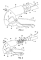
- Figure 1 is a partial front perspective view of a bicycle having a time trial or bull horn handlebar that is equipped with a pair of main bar end electric shifters (shift control devices) mounted to the free ends of the bull horn handlebar in accordance with a first embodiment;
- Figure 2 is an enlarged inside perspective view of the right bar end electric shifter attached to the right free end of the bull horn handlebar illustrated in Figure 1 ;
- Figure 3 is an inside perspective view, similar to Figure 2 , of the bar end electric shifter, but prior to attachment to the right free end of the bull horn handlebar illustrated in Figures 1 and 2 ;
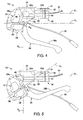
- Figure 4 is an inside elevational view of the bar end electric shifter illustrated in Figures 1 to 3 ;
- Figure 5 is an inside elevational view, similar to Figure 4 , of the bar end electric shifter, but with the brake lever moved to the braking position;
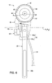
- Figure 6 is a rear end elevational view of the bar end electric shifter illustrated in Figures 1 to 5 ;
- Figure 7 is an inside elevational view of the bar end electric shifter illustrated in Figures 1 to 6 , but with the inside cover of the switch housing removed;
- Figure 8 is an outside elevational view of the bar end electric shifter illustrated in Figures 1 to 7 , but with the switch housing removed;
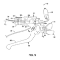
- Figure 9 is an outside elevational view of the bar end electric shifter illustrated in Figures 1 to 8 , but with the switch and the switch housing removed;
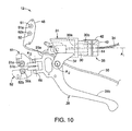
- Figure 10 is an inside elevational view of the bar end electric shifter illustrated in Figures 1 to 9 , but with the switch and the switch housing removed;
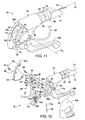
- Figure 11 is an inside perspective view of the bar end electric shifter illustrated in Figures 1 to 10 with the inside cover exploded outwardly to reveal the internal shifting components;
- Figure 12 is an inside perspective view of the bar end electric shifter illustrated in Figures 1 to 8 with the internal shifting components exploded outwardly from the electrical switch housing.
- a time trial bicycle 10 is illustrated with a pair of main bar end electric shifters 11 and 12 in accordance with a first embodiment.
- the main bar end electric shifters 11 and 12 are mounted to the free ends of a time trial or bull horn handlebar 13.
- the main bar end electric shifters 11 and 12 constitute brake/shift control devices as discussed below.
- the bull horn handlebar 13 is also provided with a pair of attachment or aero bars 14.
- the aero bars 14 are provided with additional bar end electric shifters 15 and 16, respectively.
- the additional bar end electric shifters 15 and 16 are mounted to the free ends of the aero bars 14.
- the additional bar end electric shifters 15 and 16 constitute shift control devices.
- the main bar end electric shifters 11 and 12 and the additional bar end electric shifters 15 and 16 form parts of a brake and shift control system of the bicycle 10.
- one of the main bar end electric shifters 11 and 12 and one of the additional bar end electric shifters 15 and 16 are operatively coupled to a rear derailleur (not shown), while the other ones of the main bar end electric shifters 11 and 12 and the additional bar end electric shifters 15 and 16 are operatively coupled to a front derailleur (not shown).
- the bar end electric shifters 11 and 15 are operatively coupled to a rear derailleur (not shown), while the bar end electric shifters 12 and 16 are operatively coupled to a front derailleur (not shown).
- derailleurs and braking devices as well as other conventional bicycle parts of the bicycle 10 are well known in the bicycle art, the derailleurs, the braking devices and the other bicycle parts of the bicycle 10 will not be discussed or illustrated in detail herein, except for the parts relating to the bar end electric shifters. Moreover, various conventional bicycle parts, which are not illustrated and/or discussed in detail herein, can also be used in conjunction with the bicycle 10.
- the main bar end electric shifter 12 mainly includes a base member 24, a brake lever 26 and an electrical shift control switch assembly 28.
- the base member 24 includes a handlebar mounting portion 30 and a brake lever mounting portion 32.
- the handlebar mounting portion 30 is formed at a proximal end of the base member 24 with respect to the bull horn handlebar 13.
- the brake lever mounting portion 32 is formed at a distal end of the base member 24 with respect to the bull horn handlebar 13.
- the handlebar mounting portion 30 and the brake lever mounting portion 32 are primarily formed of a hard rigid plastic material.
- the base member 24 pivotally supports the brake lever 26, which in turn supports the electrical shift control switch assembly 28.
- the brake lever 26 is connected to one end of a brake control wire 34 to mechanically operate a braking device.
- the brake control wire 34 runs along the inside of the bull horn handlebar 13, as explained below.
- the electrical shift control switch assembly 28 is electrically coupled to an electric derailleur or some other type of gear shifting device by an electrical cord 36.
- the electrical cord 36 runs along the outside of the bull horn handlebar 13, and is preferably covered by handlebar tape as seen in Figure 1
- the handlebar mounting portion 30 is configured to be fixedly mounted to a right free end of the bull horn handlebar 13 such that the electrical shift control switch assembly 28 is operable on the inwardly facing side of the base member 24, and the brake lever 26 extends downwardly and generally parallel to a main center longitudinal axis A 1 of the handlebar 13.
- the handlebar mounting portion 30 is a bar end mount that is dimensioned to fit inside the free end of the bull horn handlebar 13.
- the bar end mount that forms the handlebar mounting portion 30 has a brake control wire receiving passageway 30a extending in a longitudinal direction of the bar end mount to guide the brake control wire 34 into the free end of the bull horn handlebar 13 of the bicycle 10.
- the brake control wire receiving passageway 30a is a threaded passageway, which is formed by a metallic insert embedded in the handlebar mounting portion 30.
- an attachment structure 38 is used to mount the handlebar mounting portion 30.
- the attachment structure 38 basically has a fixing bolt 40 and three expansion members 42, which are coupled together by an expandable ring member 44.
- the fixing bolt 40 has a brake control wire receiving passageway 40a as seen in Figure 3 .
- at least part of the brake control wire receiving passageway 40a has a hexagonal cross section for receiving a hex tool such as an Allen wrench.
- the attachment structure 38 is an expandable unit that is slidable within the free end of the handlebar 13 together with the bar end mount that forms the handlebar mounting portion 30 when in a first unexpanded configuration.
- the fixing bolt 40 is threaded into the brake control wire receiving passageway 30a
- the expansion members 42 are forced into engagement with an outer tapered surface 30b of the handlebar mounting portion 30 such that the fixing bolt 40 and the handlebar mounting portion 30 push the expansion members 42 radially outward to a second expanded configuration.
- the attachment structure 38 retains the handlebar mounting portion 30 in a non-slidable state within the free end of the handlebar 13.
- the outer tapered surface 30b of the handlebar mounting portion 30 is sized to be received inside the free end of the handlebar 13.
- the outer tapered surface 30b is preferably provided with wedges that partially define a frustoconical shape.
- the expansion members 42 are preferably circumferentially arranged about a longitudinal axis of the fixing bolt 40 to move radially outwardly upon axially moving the fixing bolt 40 (i.e., screwing the fixing bolt 40 into the threaded bore of the brake control wire receiving passageway 30a).
- Each of the expansion members 42 includes a pair of opposed, arc-shaped inclined surfaces, and an outer groove.
- the expandable ring member 44 is preferably a coiled wire ring that is constructed to form a resiliently expandable ring.
- the expandable ring member 44 extends around the expansion members 42 to retain the expansion members 42 together with the fixing bolt 40.
- the arc shaped inclined surfaces of the expansion members 42 form a substantially frustoconically shaped wedge.
- the outer tapered surface 30b of the handlebar mounting portion 30 contacts the inclined surfaces of the expansion members 42.
- the brake lever 26 is pivotally disposed on the brake lever mounting portion 32 about a brake pivot axis A 2 .
- the brake lever 26 includes a proximal portion 26a surrounding the brake pivot axis A 2 and an elongated brake operating portion 26b extending from the proximal portion 26a surrounding the brake pivot axis A 2 to a free end.
- the proximal portion 26a has a U shaped brake wire attachment element 46 pivotally mounted thereto. One end the brake control wire 34 is attached to the attachment element 46, while the other end of the brake control wire 34 is attached to a brake device (not shown).
- the proximal portion 26a also supports the electrical shift control switch assembly 28 such that the electrical shift control switch assembly 28 moves with the brake lever 26 as the brake lever 26 is pivoted from a rest position ( Figure 4 ) to a braking position ( Figure 5 ).
- the relationship between the brake lever 26 and the electrical shift control switch assembly 28 remains unchanged during a braking operation.
- the electrical shift control switch assembly 28 basically includes an electrical switch 48, an electrical switch housing 50, a first electrical shift operating member 51 and a second electrical shift operating member 52. As seen in Figure 12 , the electrical shift control switch assembly 28 is electrically coupled to the electrical cord 36 which has two or more electrical conductors. The precise structure of the electrical shift control switch assembly 28 is not important to the understanding of the illustrated embodiment and can be construction in a variety of ways to carry out the shifting operation.
- the electric switch 48 is disposed on the proximal portion 26a of the brake lever 26.
- the electrical switch 48 is fixedly mounted to the proximal portion 26a of the brake lever 26 by a pair of screws 54.
- the shift operating members 51 and 52 are disposed on the proximal portion 26a of the brake lever 26 so as to move with the proximal portion 26a of the brake lever 26.
- the electrical shift operating members 51 and 52 are pivotally mounted to the proximal portion 26a of the brake lever 26 by a single pivot pin 68, and configured to activate the electric switch 48 by movement of the shift operating members 51 and 52 with respect to the brake lever 26.
- the electrical switch housing 50 houses the electrical switch 48 and holds the electrical shift operating members 51 and 52 in their neutral or rest positions against the biasing forces of return springs 58a and 58b.
- the shift operating members 51 and 52 are preferably located on a laterally inner side of the electrical switch housing 50 with respect to a vertical center plane of the bicycle 10 when the bar end electric shifter 12 is attached to the bull horn handlebar 13 of the bicycle 10.
- the electrical shift operating members 51 and 52 are located on the lateral side of the electrical switch housing 50 that faces towards the vertical center plane of the bicycle 10.
- the second electrical shift operating member 52 protrudes out from the inner cover part 50a by a greater amount than the first electrical shift operating member 51.
- the first electrical shift operating member 51 is disposed above the second electrical shift operating member 52, with the second electrical shift operating member 52 being longer in dimension than the first electrical shift operating member 51 in a direction parallel to the main center longitudinal axis A 1 of the free end of the bull horn handlebar 13.
- the second electrical shift operating member 52 is shorter in dimension than the first electrical shift operating member 51 in a direction perpendicular to the main center longitudinal axis A 1 of the free end of the bull horn handlebar 13.
- the first electrical shift operating member 51 is disposed primarily above plane P 1 containing the brake pivot axis A 2 and extending parallel to the main center longitudinal axis A 1 of the free end of the bull horn handlebar 13 when the bar end electric shifter 12 is attached to the bull horn handlebar 13 of the bicycle 10.
- the second electrical shift operating member 52 is disposed primarily below the plane P 1 when the bar end electric shifter 12 is attached to the bull horn handlebar 13 of the bicycle 10.
- the electrical shift operating members 51 and 52 are disposed on an opposite side of a plane P 2 from the handlebar mounting portion 30.
- the plane P 2 contains the brake pivot axis A 2 and extends perpendicular to the center longitudinal axis A 1 of the free end of the bull horn handlebar 13 when the bar end electric shifter 12 is attached to the bull horn handlebar 13 of the bicycle 10.
- the handlebar mounting portion 30 is disposed on a first side of the plane P 2 while the electrical shift operating members 51 and 52 are disposed on second side of the plane P 2 .
- the electrical switch housing 50 has an inner cover part 50a and an outer cover part 50b that form a hollow interior for housing the electrical switch 48.
- the brake lever 26 effectively includes the electrical switch housing 50 that enclosing the electrical switch 48.
- the inner cover part 50a forms a first lateral side of the electrical switch housing 50 that faces towards a vertical center plane of the bicycle 10 when the handlebar mounting portion 30 is mounted to the free end of the handlebar 13.
- the outer cover part 50b forms a second lateral side of the electrical switch housing 50 that is opposite to the inner cover part 50a and faces away from the vertical center plane of the bicycle 10.
- the center axis A 1 of the free end of the handlebar 13 extends longitudinally through an upper portion of the electrical switch housing 50 between the first and second lateral sides when the handlebar mounting portion 30 is mounted to the free end of the handlebar 13.
- the inner and outer cover parts 50a and 50b are fastened to the proximal portion 26a of the brake lever 26 by three fasteners 60 such as screws in a releasable and reinstallable manner.
- the inner cover part 50a is provided with three threaded holes, while the outer cover part 50b is provided with two unthreaded holes.
- the proximal portion 26a of the brake lever 26 has two holes such that two of the three fasteners 60 pass through the holes in the proximal portion 26a of the brake lever 26 when the inner and outer cover parts 50a and 50b are fastened to the proximal portion 26a of the brake lever 26.
- the inner and outer cover parts 50a and 50b can be detached from the brake lever 26.
- the electrical switch 48 can then be removed from the brake lever 26 without detaching the handlebar mounting portion 30 from the handlebar 13.
- the electrical switch 48 and the electrical shift operating members 51 and 52 cooperate together to form a pair of push buttons type switches.
- the electrical shift operating members 51 and 52 protrude outwardly from the inner cover part 50a of the electrical switch housing 50.
- the electrical shift operating members 51 and 52 pivot about an operating axis A 3 .
- the biasing forces of the return springs 58a and 58b hold the electrical shift operating members 51 and 52, respectively, in their neutral or rest positions.
- the electrical shift operating members 51 and 52 are preferably push buttons in which each are movable relative to the base member 24 from their neutral or rest position to an actuating position against the biasing forces of the return springs 58a and 58b, respectively.
- the electrical shift operating members 51 and 52 can be utilized for both downshifting and upshifting one of the derailleurs.
- the first electrical shift operating member 51 is a downshift button that depressed to downshift towards a lower gear
- the second electrical shift operating member 52 is an upshift button that depressed to upshift towards a higher gear.
- the upshifting and downshifting operations of the electrical shift operating members 51 and 52 could be reversed if needed and/or desired, depending on how the electrical cord 36 is connected.
- the electrical switch 48 includes first and second actuating buttons 61 and 62 are normally open pushbutton switches.
- the electrical switch 48 is electrically coupled to the electrical cord 36 such that a first electrical shift signal is output in response to the first electrical shift operating member 51 being depressed, which closes a first internal circuit of the electrical switch 48, and such that a second electrical shift signal is output in response to the second electrical shift operating member 52 being depressed, which closes a second internal circuit of the electrical switch 48.
- Each of the first and second actuating buttons 61 and 62 has an internal spring mechanism (not shown) that returns the actuating buttons 61 and 62 to its "out” or “unpressed” position once the shift operating member 51 or 52 is released.
- the first actuating button 61 has a projection 61a that is operated (depressed) by a contact actuating spring 63a in response to the first electrical shift operating member 51 being depressed. More specifically, one (first) end of the contact actuating spring 63a is frictionally engaged with the projection 61a, while the other (second) end of the first contact actuating spring 63a is slidably engaged with a projection 51a of the first electrical shift operating member 51.
- the first end of the contact actuating spring 63a engages the projection 61a to hold the contact actuating spring 63a in a recess on the outbound side of the electrical switch 48.
- the second end of the contact actuating spring 63a engages the projection 51a of the first electrical shift operating member 51 to hold the contact actuating spring 63a within a recess defined by a circular wall 51b of the first electrical shift operating member 51.
- the contact actuating spring 63a When the first electrical shift operating member 51 is depressed against the biasing force of the return spring 58a, the contact actuating spring 63a will initially slide on the engage the projection 51a of the first electrical shift operating member 51 and then the contact actuating spring 63a will be slightly compressed before depressing the first actuating button 61 to send a shift signal.
- the second actuating button 62 has a projection 62a that is operated (depressed) by a contact actuating spring 63b in response to the second electrical shift operating member 52. More specifically, one (first) end of the second contact actuating spring 63b is frictionally engaged with the projection 62a, while the other (second) end of the second contact actuating spring 63b is slidably engaged with a projection 52a of the second electrical shift operating member 52. The first end of the contact actuating spring 63b engages the projection 62a to hold the contact actuating spring 63b in a recess on the outbound side of the electrical switch 48.
- the second end of the contact actuating spring 63b engages the projection 52a of the second electrical shift operating member 52 to hold the contact actuating spring 63b within a recess defined by a circular wall 52b of the second electrical shift operating member 52.
- the contact actuating spring 63b will initially slide on the engage the projection 52a of the second electrical shift operating member 52 and then the contact actuating spring 63b will be slightly compressed before depressing the second actuating button 62 to send a shift signal.
- the electrical switch 48 is a conventional type of switch that is well known and thus, the details of the electrical switch 48 will not be illustrated and/or described in greater detail herein.
- the electrical switch 48 is mounted to the outbound side of the proximal portion 26a of the brake lever 26 by three fasteners 64 such as screws in a releasable and reinstallable manner.
- the electrical switch 48 overlies an opening in the proximal portion 26a of the brake lever 26 such that the actuating buttons 61 and 62 are exposed through the opening in the proximal portion 26a of the brake lever 26.
- a gasket 66 is disposed between the inbound side of the electrical switch 48 and the outbound side of the proximal portion 26a of the brake lever 26.
- the bar end electric shifters 15 and 16 are essentially identical in construction and operation, except that they are mirror images of each other. Moreover, the additional bar end electric shifters 15 and 16 are similar in construction and operation to the main bar end electric shifter 12, discussed above, except that the braking aspect of the main bar end electric shifter 12 has been eliminated from the bar end electric shifters 15 and 16.
- the term “comprising” and its derivatives, as used herein, are intended to be open ended terms that specify the presence of the stated features, elements, components, groups, integers, and/or steps, but do not exclude the presence of other unstated features, elements, components, groups, integers and/or steps.
- the foregoing also applies to words having similar meanings such as the terms, “including”, “having” and their derivatives.
- the terms “member” or “element” when used in the singular can have the dual meaning of a single part or a plurality of parts.
- terms of degree such as “substantially”, “about” and “approximately” as used herein mean a reasonable amount of deviation of the modified term such that the end result is not significantly changed.
Landscapes
- Engineering & Computer Science (AREA)
- Mechanical Engineering (AREA)
- Transportation (AREA)
- Chemical & Material Sciences (AREA)
- Combustion & Propulsion (AREA)
- Steering Devices For Bicycles And Motorcycles (AREA)
Abstract
Description
- This invention generally relates to a bicycle control device for performing a shifting operation. More specifically, the present invention relates to a bar end electric shifter with an integrated brake lever.
- Bicycling is becoming an increasingly more popular form of recreation as well as a means of transportation. Moreover, bicycling has become a very popular competitive sport for both amateurs and professionals. Whether the bicycle is used for recreation, transportation or competition, the bicycle industry is constantly improving the various components of the bicycle, especially the bicycle control devices for shifting and braking.
- In the case of a time trial bicycle, a bull horn handlebar is often used that curves forward away from the rider that allows the rider to ride in a tuck position. The bull horn handlebar is sometimes provided with a pair of aero bars or a single loop shaped aero bar. The aero bar attaches to the main bar near the stem and provides a position where the hands and fore-arms are close together, low and forward, providing a very aerodynamic (though less stable) position. Typically, each end of the bull horn handlebar is provided with a "handlebar end shifter" or "bar end shifter". These bar end shifters can include a brake lever in some instances.
- In the past, bar end shifters were mechanically operated devices that were sometimes located near the brake levers of the bicycle. Thus, an operating force was typically applied by one of the rider's fingers to operate a shift control lever, which in turn transmitted the operating force to the drive component of a bicycle shifting mechanism by a cable that was fixed at one end to the control lever. More recently, electric switches have been used instead of mechanical control levers in order to operate the bicycle shifting mechanism. One example of an electrical shift control device is disclosed in
U.S. Patent No. 5,358,451 . This patent discloses a plurality of electric switches may be provided at a plurality of handlebar locations in order to allow for quicker shifts and to enhance responsiveness. Another example of a bicycle electrical shift control device is disclosed inU.S. Patent Application Publication No. 2005/0211014 . - One object of the present invention is to provide a bar end electric shifter that can be easily operated.
- The foregoing object can basically be attained by providing a bar end electric shifter for bicycle. The bar end electric shifter comprises a base member, a brake lever and a shift operating member. The base member includes a handlebar mounting portion and a brake lever mounting portion. The handlebar mounting portion is configured to be fixedly mounted to a free end of a handlebar. The brake lever is pivotally disposed on the brake lever mounting portion about a brake pivot axis. The brake lever includes an elongated brake operating portion extending from the brake pivot axis and a proximal portion adjacent to the brake pivot axis. The shift operating member is disposed on the proximal portion of the brake lever to move therewith.
- This and other objects, features, aspects and advantages of the present invention will become apparent to those skilled in the art from the following detailed description, which, taken in conjunction with the annexed drawings, discloses a preferred embodiment.
- Referring now to the attached drawings which form a part of this original disclosure:
-
Figure 1 is a partial front perspective view of a bicycle having a time trial or bull horn handlebar that is equipped with a pair of main bar end electric shifters (shift control devices) mounted to the free ends of the bull horn handlebar in accordance with a first embodiment; -
Figure 2 is an enlarged inside perspective view of the right bar end electric shifter attached to the right free end of the bull horn handlebar illustrated inFigure 1 ; -
Figure 3 is an inside perspective view, similar toFigure 2 , of the bar end electric shifter, but prior to attachment to the right free end of the bull horn handlebar illustrated inFigures 1 and2 ; -
Figure 4 is an inside elevational view of the bar end electric shifter illustrated inFigures 1 to 3 ; -
Figure 5 is an inside elevational view, similar toFigure 4 , of the bar end electric shifter, but with the brake lever moved to the braking position; -
Figure 6 is a rear end elevational view of the bar end electric shifter illustrated inFigures 1 to 5 ; -
Figure 7 is an inside elevational view of the bar end electric shifter illustrated inFigures 1 to 6 , but with the inside cover of the switch housing removed; -
Figure 8 is an outside elevational view of the bar end electric shifter illustrated inFigures 1 to 7 , but with the switch housing removed; -
Figure 9 is an outside elevational view of the bar end electric shifter illustrated inFigures 1 to 8 , but with the switch and the switch housing removed; -
Figure 10 is an inside elevational view of the bar end electric shifter illustrated inFigures 1 to 9 , but with the switch and the switch housing removed; -
Figure 11 is an inside perspective view of the bar end electric shifter illustrated inFigures 1 to 10 with the inside cover exploded outwardly to reveal the internal shifting components; and -
Figure 12 is an inside perspective view of the bar end electric shifter illustrated inFigures 1 to 8 with the internal shifting components exploded outwardly from the electrical switch housing. - Selected embodiments of the present invention will now be explained with reference to the drawings. It will be apparent to those skilled in the art from this disclosure that the following descriptions of the embodiments are provided for illustration only and not for the purpose of limiting the invention as defined by the appended claims and their equivalents.
- Referring initially to
Figure 1 , atime trial bicycle 10 is illustrated with a pair of main bar endelectric shifters electric shifters bull horn handlebar 13. The main bar endelectric shifters bull horn handlebar 13 is also provided with a pair of attachment oraero bars 14. Theaero bars 14 are provided with additional bar endelectric shifters electric shifters aero bars 14. The additional bar endelectric shifters electric shifters electric shifters bicycle 10. - Basically, one of the main bar end
electric shifters electric shifters electric shifters electric shifters electric shifters electric shifters - Since derailleurs and braking devices as well as other conventional bicycle parts of the
bicycle 10 are well known in the bicycle art, the derailleurs, the braking devices and the other bicycle parts of thebicycle 10 will not be discussed or illustrated in detail herein, except for the parts relating to the bar end electric shifters. Moreover, various conventional bicycle parts, which are not illustrated and/or discussed in detail herein, can also be used in conjunction with thebicycle 10. - Referring now to
Figures 2 to 6 , since the main bar endelectric shifters electric shifter 12 will be discussed and illustrated in detail herein. The main bar endelectric shifter 12 mainly includes abase member 24, abrake lever 26 and an electrical shiftcontrol switch assembly 28. - Preferably, the
base member 24 includes ahandlebar mounting portion 30 and a brakelever mounting portion 32. Thehandlebar mounting portion 30 is formed at a proximal end of thebase member 24 with respect to thebull horn handlebar 13. The brakelever mounting portion 32 is formed at a distal end of thebase member 24 with respect to thebull horn handlebar 13. In the illustrated embodiment, thehandlebar mounting portion 30 and the brakelever mounting portion 32 are primarily formed of a hard rigid plastic material. Basically, thebase member 24 pivotally supports thebrake lever 26, which in turn supports the electrical shiftcontrol switch assembly 28. Thebrake lever 26 is connected to one end of abrake control wire 34 to mechanically operate a braking device. Thebrake control wire 34 runs along the inside of thebull horn handlebar 13, as explained below. The electrical shiftcontrol switch assembly 28 is electrically coupled to an electric derailleur or some other type of gear shifting device by anelectrical cord 36. Theelectrical cord 36 runs along the outside of thebull horn handlebar 13, and is preferably covered by handlebar tape as seen inFigure 1 . - As seen in
Figure 2 , thehandlebar mounting portion 30 is configured to be fixedly mounted to a right free end of thebull horn handlebar 13 such that the electrical shiftcontrol switch assembly 28 is operable on the inwardly facing side of thebase member 24, and thebrake lever 26 extends downwardly and generally parallel to a main center longitudinal axis A1 of thehandlebar 13. In particular, thehandlebar mounting portion 30 is a bar end mount that is dimensioned to fit inside the free end of thebull horn handlebar 13. As seen inFigure 4 , the bar end mount that forms thehandlebar mounting portion 30 has a brake controlwire receiving passageway 30a extending in a longitudinal direction of the bar end mount to guide thebrake control wire 34 into the free end of thebull horn handlebar 13 of thebicycle 10. Preferably, the brake controlwire receiving passageway 30a is a threaded passageway, which is formed by a metallic insert embedded in thehandlebar mounting portion 30. - As seen in
Figures 2 to 4 , anattachment structure 38 is used to mount thehandlebar mounting portion 30. Theattachment structure 38 basically has a fixingbolt 40 and threeexpansion members 42, which are coupled together by anexpandable ring member 44. The fixingbolt 40 has a brake controlwire receiving passageway 40a as seen inFigure 3 . Preferably, at least part of the brake controlwire receiving passageway 40a has a hexagonal cross section for receiving a hex tool such as an Allen wrench. - Basically, the
attachment structure 38 is an expandable unit that is slidable within the free end of thehandlebar 13 together with the bar end mount that forms thehandlebar mounting portion 30 when in a first unexpanded configuration. When the fixingbolt 40 is threaded into the brake controlwire receiving passageway 30a, theexpansion members 42 are forced into engagement with an outertapered surface 30b of thehandlebar mounting portion 30 such that the fixingbolt 40 and thehandlebar mounting portion 30 push theexpansion members 42 radially outward to a second expanded configuration. When in a second expanded configuration, theattachment structure 38 retains thehandlebar mounting portion 30 in a non-slidable state within the free end of thehandlebar 13. - The outer
tapered surface 30b of thehandlebar mounting portion 30 is sized to be received inside the free end of thehandlebar 13. The outertapered surface 30b is preferably provided with wedges that partially define a frustoconical shape. Theexpansion members 42 are preferably circumferentially arranged about a longitudinal axis of the fixingbolt 40 to move radially outwardly upon axially moving the fixing bolt 40 (i.e., screwing the fixingbolt 40 into the threaded bore of the brake controlwire receiving passageway 30a). Each of theexpansion members 42 includes a pair of opposed, arc-shaped inclined surfaces, and an outer groove. Theexpandable ring member 44 is preferably a coiled wire ring that is constructed to form a resiliently expandable ring. Theexpandable ring member 44 extends around theexpansion members 42 to retain theexpansion members 42 together with the fixingbolt 40. The arc shaped inclined surfaces of theexpansion members 42 form a substantially frustoconically shaped wedge. The outertapered surface 30b of thehandlebar mounting portion 30 contacts the inclined surfaces of theexpansion members 42. Thus, when the fixingbolt 40 is rotated to move towards the outer taperedsurface 30b of thehandlebar mounting portion 30, the inclined surfaces cooperate with inclined surfaces of the fixing bolt and the outer taperedsurface 30b, respectively, to move theexpansion members 42 and the expandable ring member 44 (i.e., the expansion structure) radially outward. - As can best be seen from
Figures 4 and 5 , thebrake lever 26 is pivotally disposed on the brakelever mounting portion 32 about a brake pivot axis A2. Thebrake lever 26 includes aproximal portion 26a surrounding the brake pivot axis A2 and an elongatedbrake operating portion 26b extending from theproximal portion 26a surrounding the brake pivot axis A2 to a free end. Theproximal portion 26a has a U shaped brakewire attachment element 46 pivotally mounted thereto. One end thebrake control wire 34 is attached to theattachment element 46, while the other end of thebrake control wire 34 is attached to a brake device (not shown). - As seen in
Figures 7, 8 ,11 and 12 , theproximal portion 26a also supports the electrical shiftcontrol switch assembly 28 such that the electrical shiftcontrol switch assembly 28 moves with thebrake lever 26 as thebrake lever 26 is pivoted from a rest position (Figure 4 ) to a braking position (Figure 5 ). Thus, the relationship between thebrake lever 26 and the electrical shiftcontrol switch assembly 28 remains unchanged during a braking operation. - As seen in
Figures 7 to 12 , the electrical shiftcontrol switch assembly 28 basically includes anelectrical switch 48, anelectrical switch housing 50, a first electricalshift operating member 51 and a second electricalshift operating member 52. As seen inFigure 12 , the electrical shiftcontrol switch assembly 28 is electrically coupled to theelectrical cord 36 which has two or more electrical conductors. The precise structure of the electrical shiftcontrol switch assembly 28 is not important to the understanding of the illustrated embodiment and can be construction in a variety of ways to carry out the shifting operation. - The
electric switch 48 is disposed on theproximal portion 26a of thebrake lever 26. In particular, theelectrical switch 48 is fixedly mounted to theproximal portion 26a of thebrake lever 26 by a pair of screws 54. Theshift operating members proximal portion 26a of thebrake lever 26 so as to move with theproximal portion 26a of thebrake lever 26. The electricalshift operating members proximal portion 26a of thebrake lever 26 by asingle pivot pin 68, and configured to activate theelectric switch 48 by movement of theshift operating members brake lever 26. - The
electrical switch housing 50 houses theelectrical switch 48 and holds the electricalshift operating members shift operating members electrical switch housing 50 with respect to a vertical center plane of thebicycle 10 when the bar endelectric shifter 12 is attached to thebull horn handlebar 13 of thebicycle 10. Thus, in this embodiment, the electricalshift operating members electrical switch housing 50 that faces towards the vertical center plane of thebicycle 10. - As seen in
Figure 4 , in this embodiment, the second electricalshift operating member 52 protrudes out from theinner cover part 50a by a greater amount than the first electricalshift operating member 51. Also in this embodiment, the first electricalshift operating member 51 is disposed above the second electricalshift operating member 52, with the second electricalshift operating member 52 being longer in dimension than the first electricalshift operating member 51 in a direction parallel to the main center longitudinal axis A1 of the free end of thebull horn handlebar 13. Also in this embodiment, the second electricalshift operating member 52 is shorter in dimension than the first electricalshift operating member 51 in a direction perpendicular to the main center longitudinal axis A1 of the free end of thebull horn handlebar 13. The first electricalshift operating member 51 is disposed primarily above plane P1 containing the brake pivot axis A2 and extending parallel to the main center longitudinal axis A1 of the free end of thebull horn handlebar 13 when the bar endelectric shifter 12 is attached to thebull horn handlebar 13 of thebicycle 10. The second electricalshift operating member 52 is disposed primarily below the plane P1 when the bar endelectric shifter 12 is attached to thebull horn handlebar 13 of thebicycle 10. - The electrical
shift operating members handlebar mounting portion 30. The plane P2 contains the brake pivot axis A2 and extends perpendicular to the center longitudinal axis A1 of the free end of thebull horn handlebar 13 when the bar endelectric shifter 12 is attached to thebull horn handlebar 13 of thebicycle 10. Thus, thehandlebar mounting portion 30 is disposed on a first side of the plane P2 while the electricalshift operating members - The
electrical switch housing 50 has aninner cover part 50a and anouter cover part 50b that form a hollow interior for housing theelectrical switch 48. Thus, thebrake lever 26 effectively includes theelectrical switch housing 50 that enclosing theelectrical switch 48. Theinner cover part 50a forms a first lateral side of theelectrical switch housing 50 that faces towards a vertical center plane of thebicycle 10 when thehandlebar mounting portion 30 is mounted to the free end of thehandlebar 13. Theouter cover part 50b forms a second lateral side of theelectrical switch housing 50 that is opposite to theinner cover part 50a and faces away from the vertical center plane of thebicycle 10. In the illustrated embodiment, the center axis A1 of the free end of thehandlebar 13 extends longitudinally through an upper portion of theelectrical switch housing 50 between the first and second lateral sides when thehandlebar mounting portion 30 is mounted to the free end of thehandlebar 13. - In the illustrated embodiment, the inner and
outer cover parts proximal portion 26a of thebrake lever 26 by threefasteners 60 such as screws in a releasable and reinstallable manner. In the illustrated embodiment, theinner cover part 50a is provided with three threaded holes, while theouter cover part 50b is provided with two unthreaded holes. Theproximal portion 26a of thebrake lever 26 has two holes such that two of the threefasteners 60 pass through the holes in theproximal portion 26a of thebrake lever 26 when the inner andouter cover parts proximal portion 26a of thebrake lever 26. When thefasteners 60 are unthreaded from holes in theinner cover part 50a, the inner andouter cover parts brake lever 26. Theelectrical switch 48 can then be removed from thebrake lever 26 without detaching thehandlebar mounting portion 30 from thehandlebar 13. - The
electrical switch 48 and the electricalshift operating members shift operating members inner cover part 50a of theelectrical switch housing 50. Preferably, the electricalshift operating members shift operating members shift operating members base member 24 from their neutral or rest position to an actuating position against the biasing forces of the return springs 58a and 58b, respectively. - Accordingly, the electrical
shift operating members shift operating member 51 is a downshift button that depressed to downshift towards a lower gear, while the second electricalshift operating member 52 is an upshift button that depressed to upshift towards a higher gear. Of course, it will be apparent to those skilled in the art from this disclosure that the upshifting and downshifting operations of the electricalshift operating members electrical cord 36 is connected. - In the illustrated embodiment, as seen in
Figure 12 , theelectrical switch 48 includes first andsecond actuating buttons electrical switch 48 is electrically coupled to theelectrical cord 36 such that a first electrical shift signal is output in response to the first electricalshift operating member 51 being depressed, which closes a first internal circuit of theelectrical switch 48, and such that a second electrical shift signal is output in response to the second electricalshift operating member 52 being depressed, which closes a second internal circuit of theelectrical switch 48. - Each of the first and
second actuating buttons actuating buttons shift operating member first actuating button 61 has aprojection 61a that is operated (depressed) by acontact actuating spring 63a in response to the first electricalshift operating member 51 being depressed. More specifically, one (first) end of thecontact actuating spring 63a is frictionally engaged with theprojection 61a, while the other (second) end of the firstcontact actuating spring 63a is slidably engaged with aprojection 51a of the first electricalshift operating member 51. The first end of thecontact actuating spring 63a engages theprojection 61a to hold thecontact actuating spring 63a in a recess on the outbound side of theelectrical switch 48. The second end of thecontact actuating spring 63a engages theprojection 51a of the first electricalshift operating member 51 to hold thecontact actuating spring 63a within a recess defined by acircular wall 51b of the first electricalshift operating member 51. When the first electricalshift operating member 51 is depressed against the biasing force of thereturn spring 58a, thecontact actuating spring 63a will initially slide on the engage theprojection 51a of the first electricalshift operating member 51 and then thecontact actuating spring 63a will be slightly compressed before depressing thefirst actuating button 61 to send a shift signal. - Similarly, the
second actuating button 62 has aprojection 62a that is operated (depressed) by a contact actuating spring 63b in response to the second electricalshift operating member 52. More specifically, one (first) end of the second contact actuating spring 63b is frictionally engaged with theprojection 62a, while the other (second) end of the second contact actuating spring 63b is slidably engaged with aprojection 52a of the second electricalshift operating member 52. The first end of the contact actuating spring 63b engages theprojection 62a to hold the contact actuating spring 63b in a recess on the outbound side of theelectrical switch 48. The second end of the contact actuating spring 63b engages theprojection 52a of the second electricalshift operating member 52 to hold the contact actuating spring 63b within a recess defined by acircular wall 52b of the second electricalshift operating member 52. When the second electricalshift operating member 52 is depressed against the biasing force of thereturn spring 58b, the contact actuating spring 63b will initially slide on the engage theprojection 52a of the second electricalshift operating member 52 and then the contact actuating spring 63b will be slightly compressed before depressing thesecond actuating button 62 to send a shift signal. Theelectrical switch 48 is a conventional type of switch that is well known and thus, the details of theelectrical switch 48 will not be illustrated and/or described in greater detail herein. - In the illustrated embodiment, as seen in
Figure 12 , theelectrical switch 48 is mounted to the outbound side of theproximal portion 26a of thebrake lever 26 by threefasteners 64 such as screws in a releasable and reinstallable manner. Theelectrical switch 48 overlies an opening in theproximal portion 26a of thebrake lever 26 such that theactuating buttons proximal portion 26a of thebrake lever 26. Agasket 66 is disposed between the inbound side of theelectrical switch 48 and the outbound side of theproximal portion 26a of thebrake lever 26. - Referring to back to
Figure 1 , since the bar endelectric shifters electric shifters electric shifter 12, discussed above, except that the braking aspect of the main bar endelectric shifter 12 has been eliminated from the bar endelectric shifters - As used herein to describe the electrical bicycle shift control device, the following directional terms "forward", "rearward", "above", "downward", "vertical", "horizontal", "below", "outbound", "inbound" and "transverse" as well as any other similar directional terms refer to those directions of a bicycle equipped with the electrical bicycle shift control device. Accordingly, these terms, as utilized to describe the shifter should be interpreted relative to a bicycle equipped with the electrical bicycle shift control device. Also in understanding the scope of the present invention, the term "comprising" and its derivatives, as used herein, are intended to be open ended terms that specify the presence of the stated features, elements, components, groups, integers, and/or steps, but do not exclude the presence of other unstated features, elements, components, groups, integers and/or steps. The foregoing also applies to words having similar meanings such as the terms, "including", "having" and their derivatives. Also, the terms "member" or "element" when used in the singular can have the dual meaning of a single part or a plurality of parts. Finally, terms of degree such as "substantially", "about" and "approximately" as used herein mean a reasonable amount of deviation of the modified term such that the end result is not significantly changed.
- While only selected embodiments have been chosen to illustrate the present invention, it will be apparent to those skilled in the art from this disclosure that various changes and modifications can be made herein without departing from the scope of the invention as defined in the appended claims. For example, while the above structures are especially useful as bar end shifters for aero bars and/or bull horn handlebars, it will be apparent to those skilled in the art from this disclosure that the above structures can be adapted to other types of shifters that are mounted to the handlebar at an area other than the bar end. Moreover, for example, the size, shape, location or orientation of the various components can be changed as needed and/or desired. Components that are shown directly connected or contacting each other can have intermediate structures disposed between them. The functions of one element can be performed by two, and vice versa. The structures and functions of one embodiment can be adopted in another embodiment. It is not necessary for all advantages to be present in a particular embodiment at the same time. Every feature which is unique from the prior art, alone or in combination with other features, also should be considered a separate description of further inventions by the applicant, including the structural and/or functional concepts embodied by such feature(s). Thus, the foregoing descriptions of the embodiments according to the present invention are provided for illustration only, and not for the purpose of limiting the invention as defined by the appended claims and their equivalents.
Claims (9)
- A bar end electric shifter for bicycle comprising;
a base member including a handlebar mounting portion and a brake lever mounting portion, with the handlebar mounting portion being configured to be fixedly mounted to a free end of a handlebar;
a brake lever pivotally disposed on the brake lever mounting portion about a brake pivot axis, the brake lever including an elongated brake operating portion extending from the brake pivot axis and a proximal portion adjacent to the brake pivot axis; and a shift operating member disposed on the proximal portion of the brake lever to move therewith. - The bar end electric shifter according to claim 1, wherein
the handlebar mounting portion is disposed on a first side of a plane containing the brake pivot axis and extending perpendicular to a center longitudinal axis of the free end of the handlebar when the bar end electric shifter is attached to the handlebar of the bicycle, and
the shift operating member is at least partially disposed on a second side of the plane containing the brake pivot axis and extending perpendicular to the center longitudinal axis of the free end of the handlebar when the bar end electric shifter is attached to the handlebar of the bicycle. - The bar end electric shifter according to claim 1 or 2, further comprising an electric switch disposed on the proximal portion of the brake lever and configured to be activated by movement of the shift operating member with respect to the brake lever.
- The bar end electric shifter according to any one of claims 1 to 3, wherein
the shift operating member is at least partially disposed above a plane containing the brake pivot axis and extending parallel to a center longitudinal axis of the free end of the handlebar when the bar end electric shifter is attached to the handlebar of the bicycle. - The bar end electric shifter according to any one of claims 1 to 4, further comprising an additional shift operating member disposed on the brake lever.
- The bar end electric shifter according to claim 5, wherein
the shift operating member is disposed primarily above a plane containing the brake pivot axis and extending parallel to a center longitudinal axis of the free end of the handlebar when the bar end electric shifter is attached to the handlebar of the bicycle, and
the additional shift operating member is disposed primarily below a plane containing the brake pivot axis and extending parallel to a center longitudinal axis of the free end of the handlebar when the bar end electric shifter is attached to the handlebar of the bicycle. - The bar end electric shifter according to any one of claims 1 to 6, wherein
the shift operating member is located on a laterally inner side of the brake lever with respect to a center plane of a bicycle when the bar end electric shifter is attached to the handlebar of the bicycle. - The bar end electric shifter according to any one of claims 1 to 7, wherein
the brake lever has a housing that enclosing the electric switch. - The bar end electric shifter according to any one of claims 1 to 8, wherein
the handlebar mounting portion is a bar end mount that is dimensioned to fit inside the free end of the handlebar, with the bar end mount having a brake control wire receiving passageway extending in a longitudinal direction of the bar end mount to guide a brake control wire into the free end of the handlebar.
Applications Claiming Priority (1)
| Application Number | Priority Date | Filing Date | Title |
|---|---|---|---|
| US12/503,892 US9394031B2 (en) | 2009-07-16 | 2009-07-16 | Bar end electric shifter for bicycle |
Publications (2)
| Publication Number | Publication Date |
|---|---|
| EP2275338A1 true EP2275338A1 (en) | 2011-01-19 |
| EP2275338B1 EP2275338B1 (en) | 2016-04-13 |
Family
ID=42041995
Family Applications (1)
| Application Number | Title | Priority Date | Filing Date |
|---|---|---|---|
| EP10151043.6A Active EP2275338B1 (en) | 2009-07-16 | 2010-01-19 | Bar end electric shifter for a bicycle |
Country Status (2)
| Country | Link |
|---|---|
| US (1) | US9394031B2 (en) |
| EP (1) | EP2275338B1 (en) |
Cited By (5)
| Publication number | Priority date | Publication date | Assignee | Title |
|---|---|---|---|---|
| EP2657121A1 (en) * | 2012-04-23 | 2013-10-30 | Campagnolo S.r.l. | Bar-end electric actuation device of a bicycle gearshift |
| EP2921395A1 (en) * | 2014-03-18 | 2015-09-23 | Askoll Eva S.R.L. | Brake operating device for electric bicycles |
| US9821884B2 (en) | 2015-05-29 | 2017-11-21 | Shimano Inc. | Bicycle operating device |
| US10279867B2 (en) | 2015-05-29 | 2019-05-07 | Shimano Inc. | Bicycle operating device |
| WO2021006746A1 (en) | 2019-07-08 | 2021-01-14 | Bikefinder As | Device for fixing equipment to an end of the inner surface of a tube |
Families Citing this family (23)
| Publication number | Priority date | Publication date | Assignee | Title |
|---|---|---|---|---|
| US9394031B2 (en) * | 2009-07-16 | 2016-07-19 | Shimano Inc. | Bar end electric shifter for bicycle |
| EP2562070B1 (en) * | 2011-08-26 | 2015-02-18 | Campagnolo S.r.l. | Actuation device of a bar-end bicycle gearshift |
| US20130047774A1 (en) * | 2011-08-26 | 2013-02-28 | Retro Shift Llc | Bicycle brake and shift lever assembly |
| KR101351843B1 (en) * | 2012-05-02 | 2014-01-16 | 한국야금 주식회사 | Hard coating film for cutting tools |
| US9630677B2 (en) * | 2012-06-15 | 2017-04-25 | Sram, Llc | Brake control apparatus |
| TW201427863A (en) * | 2013-01-10 | 2014-07-16 | Ad Ii Engineering Inc | Electrical shift controller and bike handlebar using the same |
| JP2014231331A (en) * | 2013-05-30 | 2014-12-11 | 株式会社シマノ | Manipulator |
| WO2015039127A1 (en) * | 2013-09-16 | 2015-03-19 | Recreation Systems, Inc. | Handle assembly and associated components for a cycle |
| US20150145230A1 (en) * | 2013-11-26 | 2015-05-28 | BikeStreet USA | Bicycle brake system |
| US9896150B2 (en) | 2015-01-30 | 2018-02-20 | Shimano Inc. | Bicycle operating device |
| TWI678312B (en) * | 2014-08-25 | 2019-12-01 | 日商島野股份有限公司 | Bar-end type bicycle hydraulic operating device |
| US10550858B2 (en) * | 2014-08-25 | 2020-02-04 | Shimano Inc. | Bicycle control device |
| JP2019511378A (en) | 2016-03-31 | 2019-04-25 | ヴァルター アーゲー | Coated cutting tools with h-AlN and Ti1-xAlxCyNz layers |
| JP2018001883A (en) | 2016-06-28 | 2018-01-11 | 株式会社シマノ | Bar end for bicycle |
| JP7036535B2 (en) * | 2016-11-30 | 2022-03-15 | 株式会社シマノ | Electronic devices and control methods for electronic devices |
| US10589818B2 (en) | 2017-01-25 | 2020-03-17 | Shimano Inc. | Bicycle operating device |
| US10759495B2 (en) * | 2018-01-12 | 2020-09-01 | Tien Hsin Industries Co., Ltd. | Integrated control device and integrated handlebar for bicycle |
| DE202018002222U1 (en) * | 2018-05-05 | 2019-09-09 | Canyon Bicycles Gmbh | Control element for a bicycle |
| US11505271B2 (en) | 2020-05-27 | 2022-11-22 | Shimano Inc. | Operating device |
| US11565766B2 (en) | 2020-05-27 | 2023-01-31 | Shimano Inc. | Operating device |
| US11587747B2 (en) | 2020-11-30 | 2023-02-21 | Shimano Inc. | Operating device |
| US11577800B2 (en) | 2020-11-30 | 2023-02-14 | Shimano Inc. | Operating device |
| DE102021107138A1 (en) | 2021-03-23 | 2022-09-29 | Shimano Inc. | CONTROL SYSTEM OF A MUSCLE-POWERED VEHICLE |
Citations (8)
| Publication number | Priority date | Publication date | Assignee | Title |
|---|---|---|---|---|
| US5358451A (en) | 1992-02-27 | 1994-10-25 | B. G. Innovation (S.A.R.L.) | Devices enabling shifting of gears on bicycles |
| EP0790173A1 (en) * | 1996-02-14 | 1997-08-20 | Shimano Inc. | Extension handle for a bicycle shifting device |
| EP0891009A2 (en) * | 1997-06-24 | 1999-01-13 | Shimano Inc. | Flat cable connector for a bicycle |
| US20010012978A1 (en) * | 1996-12-20 | 2001-08-09 | Masahiko Jinbo | Electrical operating device for bicycles |
| US20010053724A1 (en) * | 2000-06-06 | 2001-12-20 | Campagnolo S.R.L | Electrical control device for a motor-driven derailleur for bicycles |
| EP1245482A2 (en) * | 2001-03-28 | 2002-10-02 | Shimano Inc. | Bicycle handlebar |
| EP1808367A2 (en) * | 2006-01-13 | 2007-07-18 | Shimano Inc. | Bicycle control device |
| WO2009011110A1 (en) * | 2007-07-14 | 2009-01-22 | Kouji Uno | Bicycle brake operating device |
Family Cites Families (15)
| Publication number | Priority date | Publication date | Assignee | Title |
|---|---|---|---|---|
| US4462267A (en) | 1980-03-01 | 1984-07-31 | Shimano Industrial Company, Limited | Handlebar for a bicycle |
| JP3510442B2 (en) | 1997-01-14 | 2004-03-29 | 株式会社シマノ | Bicycle electric shifting mechanism |
| US6729203B2 (en) * | 2002-06-04 | 2004-05-04 | Sram Corporation | Bicycle gear shifter having separate shift control members for cable pull and release |
| ATE367305T1 (en) * | 2003-05-05 | 2007-08-15 | Campagnolo Srl | ELECTRONIC SERVO-ASSISTED BICYCLE GEAR SHIFTING |
| US6991081B2 (en) | 2003-11-26 | 2006-01-31 | Shimano Inc. | Shift and break control device |
| US7350436B2 (en) | 2004-03-29 | 2008-04-01 | Shimano, Inc. | Electrical bicycle shift control device |
| US20070193387A1 (en) | 2006-02-03 | 2007-08-23 | Shimano Inc. | Bicycle shift control device |
| US20070193388A1 (en) * | 2006-02-03 | 2007-08-23 | Shimano Inc. | Bicycle shift control device |
| JP4366390B2 (en) | 2006-10-13 | 2009-11-18 | 株式会社シマノ | Bicycle handlebar assembly |
| JP4395504B2 (en) | 2006-11-29 | 2010-01-13 | 株式会社シマノ | Bicycle shifting operation device |
| JP2008168751A (en) * | 2007-01-11 | 2008-07-24 | Shimano Inc | Brake and gear shift operating device for bicycle |
| JP2009029345A (en) | 2007-07-30 | 2009-02-12 | Shimano Inc | Brake for bicycle, and gearshift operating device |
| US8056439B2 (en) * | 2007-11-06 | 2011-11-15 | Shimano Inc. | Device to mount control lever to bicycle |
| US7908940B2 (en) | 2008-03-24 | 2011-03-22 | Shimano Inc. | Bar end electric shifter |
| US9394031B2 (en) * | 2009-07-16 | 2016-07-19 | Shimano Inc. | Bar end electric shifter for bicycle |
-
2009
- 2009-07-16 US US12/503,892 patent/US9394031B2/en active Active
-
2010
- 2010-01-19 EP EP10151043.6A patent/EP2275338B1/en active Active
Patent Citations (8)
| Publication number | Priority date | Publication date | Assignee | Title |
|---|---|---|---|---|
| US5358451A (en) | 1992-02-27 | 1994-10-25 | B. G. Innovation (S.A.R.L.) | Devices enabling shifting of gears on bicycles |
| EP0790173A1 (en) * | 1996-02-14 | 1997-08-20 | Shimano Inc. | Extension handle for a bicycle shifting device |
| US20010012978A1 (en) * | 1996-12-20 | 2001-08-09 | Masahiko Jinbo | Electrical operating device for bicycles |
| EP0891009A2 (en) * | 1997-06-24 | 1999-01-13 | Shimano Inc. | Flat cable connector for a bicycle |
| US20010053724A1 (en) * | 2000-06-06 | 2001-12-20 | Campagnolo S.R.L | Electrical control device for a motor-driven derailleur for bicycles |
| EP1245482A2 (en) * | 2001-03-28 | 2002-10-02 | Shimano Inc. | Bicycle handlebar |
| EP1808367A2 (en) * | 2006-01-13 | 2007-07-18 | Shimano Inc. | Bicycle control device |
| WO2009011110A1 (en) * | 2007-07-14 | 2009-01-22 | Kouji Uno | Bicycle brake operating device |
Cited By (9)
| Publication number | Priority date | Publication date | Assignee | Title |
|---|---|---|---|---|
| EP2657121A1 (en) * | 2012-04-23 | 2013-10-30 | Campagnolo S.r.l. | Bar-end electric actuation device of a bicycle gearshift |
| US9958058B2 (en) | 2012-04-23 | 2018-05-01 | Campagnolo S.R.L. | Bar-end electric actuation device of a bicycle gearshift |
| EP2921395A1 (en) * | 2014-03-18 | 2015-09-23 | Askoll Eva S.R.L. | Brake operating device for electric bicycles |
| US9475542B2 (en) | 2014-03-18 | 2016-10-25 | Askoll Eva S.R.L. | Brake for electric bicycle |
| US9821884B2 (en) | 2015-05-29 | 2017-11-21 | Shimano Inc. | Bicycle operating device |
| US10279867B2 (en) | 2015-05-29 | 2019-05-07 | Shimano Inc. | Bicycle operating device |
| US11008067B2 (en) | 2015-05-29 | 2021-05-18 | Shimano Inc. | Bicycle operating device |
| WO2021006746A1 (en) | 2019-07-08 | 2021-01-14 | Bikefinder As | Device for fixing equipment to an end of the inner surface of a tube |
| US11982308B2 (en) | 2019-07-08 | 2024-05-14 | Bikefinder As | Device for fixing equipment to an end of the inner surface of a tube |
Also Published As
| Publication number | Publication date |
|---|---|
| EP2275338B1 (en) | 2016-04-13 |
| US20110011197A1 (en) | 2011-01-20 |
| US9394031B2 (en) | 2016-07-19 |
Similar Documents
| Publication | Publication Date | Title |
|---|---|---|
| EP2275338B1 (en) | Bar end electric shifter for a bicycle | |
| US7908940B2 (en) | Bar end electric shifter | |
| EP2253531B1 (en) | Electrical bicycle shift control device | |
| EP1526069B1 (en) | Electrical shift control device for a bicycle transmission | |
| US7565848B2 (en) | Bicycle control device | |
| US7350436B2 (en) | Electrical bicycle shift control device | |
| EP1588933B1 (en) | Electrical bicycle shift control device | |
| EP1787903B1 (en) | Bicycle operating component with electrical shift control switch | |
| US5617761A (en) | Shifting apparatus for a bicycle | |
| EP1816066B1 (en) | Electrical bicycle shift control device | |
| EP1535829A3 (en) | Bicycle control device | |
| US20120200061A1 (en) | Dual shifter for a bicycle | |
| EP2174863A2 (en) | Bicycle component body assembly | |
| EP1816062B1 (en) | Bicycle shift control device | |
| EP0875446B1 (en) | Bicycle shift control device having spaced apart operating units | |
| US20130145884A1 (en) | Unknown |
Legal Events
| Date | Code | Title | Description |
|---|---|---|---|
| PUAI | Public reference made under article 153(3) epc to a published international application that has entered the european phase |
Free format text: ORIGINAL CODE: 0009012 |
|
| AK | Designated contracting states |
Kind code of ref document: A1 Designated state(s): AT BE BG CH CY CZ DE DK EE ES FI FR GB GR HR HU IE IS IT LI LT LU LV MC MK MT NL NO PL PT RO SE SI SK SM TR |
|
| AX | Request for extension of the european patent |
Extension state: AL BA RS |
|
| 17P | Request for examination filed |
Effective date: 20110719 |
|
| 17Q | First examination report despatched |
Effective date: 20120229 |
|
| RIC1 | Information provided on ipc code assigned before grant |
Ipc: B62K 23/06 20060101ALI20150904BHEP Ipc: B62M 25/08 20060101ALI20150904BHEP Ipc: B62K 23/02 20060101ALI20150904BHEP Ipc: B62M 25/04 20060101AFI20150904BHEP Ipc: B62L 3/02 20060101ALI20150904BHEP Ipc: B60T 7/08 20060101ALI20150904BHEP Ipc: B60T 7/10 20060101ALI20150904BHEP |
|
| GRAP | Despatch of communication of intention to grant a patent |
Free format text: ORIGINAL CODE: EPIDOSNIGR1 |
|
| INTG | Intention to grant announced |
Effective date: 20151020 |
|
| RIN1 | Information on inventor provided before grant (corrected) |
Inventor name: FUJII, KAZUHIRO Inventor name: OKU, KIWAME |
|
| GRAS | Grant fee paid |
Free format text: ORIGINAL CODE: EPIDOSNIGR3 |
|
| GRAA | (expected) grant |
Free format text: ORIGINAL CODE: 0009210 |
|
| AK | Designated contracting states |
Kind code of ref document: B1 Designated state(s): AT BE BG CH CY CZ DE DK EE ES FI FR GB GR HR HU IE IS IT LI LT LU LV MC MK MT NL NO PL PT RO SE SI SK SM TR |
|
| REG | Reference to a national code |
Ref country code: GB Ref legal event code: FG4D |
|
| REG | Reference to a national code |
Ref country code: AT Ref legal event code: REF Ref document number: 789798 Country of ref document: AT Kind code of ref document: T Effective date: 20160415 Ref country code: CH Ref legal event code: EP |
|
| REG | Reference to a national code |
Ref country code: IE Ref legal event code: FG4D |
|
| REG | Reference to a national code |
Ref country code: DE Ref legal event code: R096 Ref document number: 602010032176 Country of ref document: DE |
|
| REG | Reference to a national code |
Ref country code: LT Ref legal event code: MG4D |
|
| REG | Reference to a national code |
Ref country code: AT Ref legal event code: MK05 Ref document number: 789798 Country of ref document: AT Kind code of ref document: T Effective date: 20160413 |
|
| REG | Reference to a national code |
Ref country code: NL Ref legal event code: MP Effective date: 20160413 |
|
| PG25 | Lapsed in a contracting state [announced via postgrant information from national office to epo] |
Ref country code: NL Free format text: LAPSE BECAUSE OF FAILURE TO SUBMIT A TRANSLATION OF THE DESCRIPTION OR TO PAY THE FEE WITHIN THE PRESCRIBED TIME-LIMIT Effective date: 20160413 Ref country code: NO Free format text: LAPSE BECAUSE OF FAILURE TO SUBMIT A TRANSLATION OF THE DESCRIPTION OR TO PAY THE FEE WITHIN THE PRESCRIBED TIME-LIMIT Effective date: 20160713 Ref country code: FI Free format text: LAPSE BECAUSE OF FAILURE TO SUBMIT A TRANSLATION OF THE DESCRIPTION OR TO PAY THE FEE WITHIN THE PRESCRIBED TIME-LIMIT Effective date: 20160413 Ref country code: PL Free format text: LAPSE BECAUSE OF FAILURE TO SUBMIT A TRANSLATION OF THE DESCRIPTION OR TO PAY THE FEE WITHIN THE PRESCRIBED TIME-LIMIT Effective date: 20160413 Ref country code: LT Free format text: LAPSE BECAUSE OF FAILURE TO SUBMIT A TRANSLATION OF THE DESCRIPTION OR TO PAY THE FEE WITHIN THE PRESCRIBED TIME-LIMIT Effective date: 20160413 |
|
| PG25 | Lapsed in a contracting state [announced via postgrant information from national office to epo] |
Ref country code: PT Free format text: LAPSE BECAUSE OF FAILURE TO SUBMIT A TRANSLATION OF THE DESCRIPTION OR TO PAY THE FEE WITHIN THE PRESCRIBED TIME-LIMIT Effective date: 20160816 Ref country code: LV Free format text: LAPSE BECAUSE OF FAILURE TO SUBMIT A TRANSLATION OF THE DESCRIPTION OR TO PAY THE FEE WITHIN THE PRESCRIBED TIME-LIMIT Effective date: 20160413 Ref country code: SE Free format text: LAPSE BECAUSE OF FAILURE TO SUBMIT A TRANSLATION OF THE DESCRIPTION OR TO PAY THE FEE WITHIN THE PRESCRIBED TIME-LIMIT Effective date: 20160413 Ref country code: ES Free format text: LAPSE BECAUSE OF FAILURE TO SUBMIT A TRANSLATION OF THE DESCRIPTION OR TO PAY THE FEE WITHIN THE PRESCRIBED TIME-LIMIT Effective date: 20160413 Ref country code: AT Free format text: LAPSE BECAUSE OF FAILURE TO SUBMIT A TRANSLATION OF THE DESCRIPTION OR TO PAY THE FEE WITHIN THE PRESCRIBED TIME-LIMIT Effective date: 20160413 Ref country code: GR Free format text: LAPSE BECAUSE OF FAILURE TO SUBMIT A TRANSLATION OF THE DESCRIPTION OR TO PAY THE FEE WITHIN THE PRESCRIBED TIME-LIMIT Effective date: 20160714 Ref country code: HR Free format text: LAPSE BECAUSE OF FAILURE TO SUBMIT A TRANSLATION OF THE DESCRIPTION OR TO PAY THE FEE WITHIN THE PRESCRIBED TIME-LIMIT Effective date: 20160413 |
|
| PG25 | Lapsed in a contracting state [announced via postgrant information from national office to epo] |
Ref country code: BE Free format text: LAPSE BECAUSE OF FAILURE TO SUBMIT A TRANSLATION OF THE DESCRIPTION OR TO PAY THE FEE WITHIN THE PRESCRIBED TIME-LIMIT Effective date: 20160413 |
|
| REG | Reference to a national code |
Ref country code: DE Ref legal event code: R097 Ref document number: 602010032176 Country of ref document: DE |
|
| PG25 | Lapsed in a contracting state [announced via postgrant information from national office to epo] |
Ref country code: EE Free format text: LAPSE BECAUSE OF FAILURE TO SUBMIT A TRANSLATION OF THE DESCRIPTION OR TO PAY THE FEE WITHIN THE PRESCRIBED TIME-LIMIT Effective date: 20160413 Ref country code: RO Free format text: LAPSE BECAUSE OF FAILURE TO SUBMIT A TRANSLATION OF THE DESCRIPTION OR TO PAY THE FEE WITHIN THE PRESCRIBED TIME-LIMIT Effective date: 20160413 Ref country code: SK Free format text: LAPSE BECAUSE OF FAILURE TO SUBMIT A TRANSLATION OF THE DESCRIPTION OR TO PAY THE FEE WITHIN THE PRESCRIBED TIME-LIMIT Effective date: 20160413 Ref country code: CZ Free format text: LAPSE BECAUSE OF FAILURE TO SUBMIT A TRANSLATION OF THE DESCRIPTION OR TO PAY THE FEE WITHIN THE PRESCRIBED TIME-LIMIT Effective date: 20160413 Ref country code: DK Free format text: LAPSE BECAUSE OF FAILURE TO SUBMIT A TRANSLATION OF THE DESCRIPTION OR TO PAY THE FEE WITHIN THE PRESCRIBED TIME-LIMIT Effective date: 20160413 |
|
| PLBE | No opposition filed within time limit |
Free format text: ORIGINAL CODE: 0009261 |
|
| STAA | Information on the status of an ep patent application or granted ep patent |
Free format text: STATUS: NO OPPOSITION FILED WITHIN TIME LIMIT |
|
| PG25 | Lapsed in a contracting state [announced via postgrant information from national office to epo] |
Ref country code: SM Free format text: LAPSE BECAUSE OF FAILURE TO SUBMIT A TRANSLATION OF THE DESCRIPTION OR TO PAY THE FEE WITHIN THE PRESCRIBED TIME-LIMIT Effective date: 20160413 |
|
| 26N | No opposition filed |
Effective date: 20170116 |
|
| PG25 | Lapsed in a contracting state [announced via postgrant information from national office to epo] |
Ref country code: SI Free format text: LAPSE BECAUSE OF FAILURE TO SUBMIT A TRANSLATION OF THE DESCRIPTION OR TO PAY THE FEE WITHIN THE PRESCRIBED TIME-LIMIT Effective date: 20160413 |
|
| REG | Reference to a national code |
Ref country code: CH Ref legal event code: PL |
|
| GBPC | Gb: european patent ceased through non-payment of renewal fee |
Effective date: 20170119 |
|
| PG25 | Lapsed in a contracting state [announced via postgrant information from national office to epo] |
Ref country code: MC Free format text: LAPSE BECAUSE OF FAILURE TO SUBMIT A TRANSLATION OF THE DESCRIPTION OR TO PAY THE FEE WITHIN THE PRESCRIBED TIME-LIMIT Effective date: 20160413 |
|
| REG | Reference to a national code |
Ref country code: FR Ref legal event code: ST Effective date: 20170929 |
|
| PG25 | Lapsed in a contracting state [announced via postgrant information from national office to epo] |
Ref country code: LI Free format text: LAPSE BECAUSE OF NON-PAYMENT OF DUE FEES Effective date: 20170131 Ref country code: FR Free format text: LAPSE BECAUSE OF NON-PAYMENT OF DUE FEES Effective date: 20170131 Ref country code: CH Free format text: LAPSE BECAUSE OF NON-PAYMENT OF DUE FEES Effective date: 20170131 |
|
| REG | Reference to a national code |
Ref country code: IE Ref legal event code: MM4A |
|
| PG25 | Lapsed in a contracting state [announced via postgrant information from national office to epo] |
Ref country code: LU Free format text: LAPSE BECAUSE OF NON-PAYMENT OF DUE FEES Effective date: 20170119 Ref country code: GB Free format text: LAPSE BECAUSE OF NON-PAYMENT OF DUE FEES Effective date: 20170119 |
|
| PG25 | Lapsed in a contracting state [announced via postgrant information from national office to epo] |
Ref country code: IE Free format text: LAPSE BECAUSE OF NON-PAYMENT OF DUE FEES Effective date: 20170119 |
|
| PG25 | Lapsed in a contracting state [announced via postgrant information from national office to epo] |
Ref country code: MT Free format text: LAPSE BECAUSE OF NON-PAYMENT OF DUE FEES Effective date: 20170119 |
|
| PG25 | Lapsed in a contracting state [announced via postgrant information from national office to epo] |
Ref country code: HU Free format text: LAPSE BECAUSE OF FAILURE TO SUBMIT A TRANSLATION OF THE DESCRIPTION OR TO PAY THE FEE WITHIN THE PRESCRIBED TIME-LIMIT; INVALID AB INITIO Effective date: 20100119 |
|
| PG25 | Lapsed in a contracting state [announced via postgrant information from national office to epo] |
Ref country code: BG Free format text: LAPSE BECAUSE OF FAILURE TO SUBMIT A TRANSLATION OF THE DESCRIPTION OR TO PAY THE FEE WITHIN THE PRESCRIBED TIME-LIMIT Effective date: 20160413 |
|
| PG25 | Lapsed in a contracting state [announced via postgrant information from national office to epo] |
Ref country code: CY Free format text: LAPSE BECAUSE OF NON-PAYMENT OF DUE FEES Effective date: 20160413 |
|
| PG25 | Lapsed in a contracting state [announced via postgrant information from national office to epo] |
Ref country code: MK Free format text: LAPSE BECAUSE OF FAILURE TO SUBMIT A TRANSLATION OF THE DESCRIPTION OR TO PAY THE FEE WITHIN THE PRESCRIBED TIME-LIMIT Effective date: 20160413 |
|
| PG25 | Lapsed in a contracting state [announced via postgrant information from national office to epo] |
Ref country code: TR Free format text: LAPSE BECAUSE OF FAILURE TO SUBMIT A TRANSLATION OF THE DESCRIPTION OR TO PAY THE FEE WITHIN THE PRESCRIBED TIME-LIMIT Effective date: 20160413 |
|
| PG25 | Lapsed in a contracting state [announced via postgrant information from national office to epo] |
Ref country code: IS Free format text: LAPSE BECAUSE OF FAILURE TO SUBMIT A TRANSLATION OF THE DESCRIPTION OR TO PAY THE FEE WITHIN THE PRESCRIBED TIME-LIMIT Effective date: 20160813 |
|
| REG | Reference to a national code |
Ref country code: DE Ref legal event code: R082 Ref document number: 602010032176 Country of ref document: DE Representative=s name: SONNENBERG HARRISON PARTNERSCHAFT MBB, DE Ref country code: DE Ref legal event code: R082 Ref document number: 602010032176 Country of ref document: DE Representative=s name: SONNENBERG HARRISON PARTNERSCHAFT MBB PATENT- , DE |
|
| PGFP | Annual fee paid to national office [announced via postgrant information from national office to epo] |
Ref country code: IT Payment date: 20220120 Year of fee payment: 13 |
|
| P01 | Opt-out of the competence of the unified patent court (upc) registered |
Effective date: 20230424 |
|
| PG25 | Lapsed in a contracting state [announced via postgrant information from national office to epo] |
Ref country code: IT Free format text: LAPSE BECAUSE OF NON-PAYMENT OF DUE FEES Effective date: 20230119 |
|
| PGFP | Annual fee paid to national office [announced via postgrant information from national office to epo] |
Ref country code: DE Payment date: 20260121 Year of fee payment: 17 |