EP2275292A1 - Kraftfahrzeugklimaanlage - Google Patents
Kraftfahrzeugklimaanlage Download PDFInfo
- Publication number
- EP2275292A1 EP2275292A1 EP09290569A EP09290569A EP2275292A1 EP 2275292 A1 EP2275292 A1 EP 2275292A1 EP 09290569 A EP09290569 A EP 09290569A EP 09290569 A EP09290569 A EP 09290569A EP 2275292 A1 EP2275292 A1 EP 2275292A1
- Authority
- EP
- European Patent Office
- Prior art keywords
- plug
- motor vehicle
- high voltage
- air conditioning
- conditioning system
- Prior art date
- Legal status (The legal status is an assumption and is not a legal conclusion. Google has not performed a legal analysis and makes no representation as to the accuracy of the status listed.)
- Granted
Links
Images
Classifications
-
- B—PERFORMING OPERATIONS; TRANSPORTING
- B60—VEHICLES IN GENERAL
- B60H—ARRANGEMENTS OF HEATING, COOLING, VENTILATING OR OTHER AIR-TREATING DEVICES SPECIALLY ADAPTED FOR PASSENGER OR GOODS SPACES OF VEHICLES
- B60H1/00—Heating, cooling or ventilating devices
- B60H1/22—Heating, cooling or ventilating devices the heat source being other than the propulsion plant
- B60H1/2215—Heating, cooling or ventilating devices the heat source being other than the propulsion plant the heat being derived from electric heaters
- B60H1/2225—Heating, cooling or ventilating devices the heat source being other than the propulsion plant the heat being derived from electric heaters arrangements of electric heaters for heating air
-
- B—PERFORMING OPERATIONS; TRANSPORTING
- B60—VEHICLES IN GENERAL
- B60H—ARRANGEMENTS OF HEATING, COOLING, VENTILATING OR OTHER AIR-TREATING DEVICES SPECIALLY ADAPTED FOR PASSENGER OR GOODS SPACES OF VEHICLES
- B60H1/00—Heating, cooling or ventilating devices
- B60H1/00357—Air-conditioning arrangements specially adapted for particular vehicles
- B60H1/00385—Air-conditioning arrangements specially adapted for particular vehicles for vehicles having an electrical drive, e.g. hybrid or fuel cell
- B60H1/00392—Air-conditioning arrangements specially adapted for particular vehicles for vehicles having an electrical drive, e.g. hybrid or fuel cell for electric vehicles having only electric drive means
-
- B—PERFORMING OPERATIONS; TRANSPORTING
- B60—VEHICLES IN GENERAL
- B60H—ARRANGEMENTS OF HEATING, COOLING, VENTILATING OR OTHER AIR-TREATING DEVICES SPECIALLY ADAPTED FOR PASSENGER OR GOODS SPACES OF VEHICLES
- B60H1/00—Heating, cooling or ventilating devices
- B60H1/00421—Driving arrangements for parts of a vehicle air-conditioning
- B60H1/00428—Driving arrangements for parts of a vehicle air-conditioning electric
-
- B—PERFORMING OPERATIONS; TRANSPORTING
- B60—VEHICLES IN GENERAL
- B60H—ARRANGEMENTS OF HEATING, COOLING, VENTILATING OR OTHER AIR-TREATING DEVICES SPECIALLY ADAPTED FOR PASSENGER OR GOODS SPACES OF VEHICLES
- B60H1/00—Heating, cooling or ventilating devices
- B60H1/22—Heating, cooling or ventilating devices the heat source being other than the propulsion plant
- B60H2001/2268—Constructional features
- B60H2001/2278—Connectors, water supply, housing, mounting brackets
-
- Y—GENERAL TAGGING OF NEW TECHNOLOGICAL DEVELOPMENTS; GENERAL TAGGING OF CROSS-SECTIONAL TECHNOLOGIES SPANNING OVER SEVERAL SECTIONS OF THE IPC; TECHNICAL SUBJECTS COVERED BY FORMER USPC CROSS-REFERENCE ART COLLECTIONS [XRACs] AND DIGESTS
- Y02—TECHNOLOGIES OR APPLICATIONS FOR MITIGATION OR ADAPTATION AGAINST CLIMATE CHANGE
- Y02T—CLIMATE CHANGE MITIGATION TECHNOLOGIES RELATED TO TRANSPORTATION
- Y02T10/00—Road transport of goods or passengers
- Y02T10/80—Technologies aiming to reduce greenhouse gasses emissions common to all road transportation technologies
- Y02T10/88—Optimized components or subsystems, e.g. lighting, actively controlled glasses
Definitions
- the invention relates to an automotive air conditioning system according to the preamble of claim 1.
- Automotive air conditioning systems serve to heat and / or to cool the air to be supplied to an interior of a motor vehicle.
- the motor vehicle air conditioning system comprises a heating device for heating the air and an evaporator for cooling the air.
- the evaporator is part of a refrigerant circuit with a compressor and a condenser.
- the heating means an electric heater and / or a heat exchanger for heating the air by means of cooling liquid from achenkeKsniklauf an internal combustion engine of the motor vehicle can be used.
- Electric vehicles no longer have an internal combustion engine and hybrid vehicles Although still have an internal combustion engine, which is only partially used and sometimes the hybrid vehicle is also rubbed only by an electric motor as the electric vehicle.
- the electric heaters are generally so-called PTC heating elements (PTC: Positive Temperature Coefficient).
- Electric and hybrid vehicles are operated to transmit the high electrical power while a high voltage circuit of at least 40 V, z. B. is a high voltage circuit in the electric or hybrid vehicle with a voltage of 300 V.
- the heating of the air is done only by the electric heater, is also for the electric heater requires a high electric power and thus the electric heater is operated with high voltage in the electric or hybrid vehicle.
- the electrical heating device is connected to a high voltage source in the manufacture or assembly of the motor vehicle.
- the DE 103 44 704 A1 shows a built-in module for a passage in an end wall of a passenger compartment of a motor vehicle, wherein in particular the end wall is used for both left and right steered vehicles, the built-in module consists of a reinforced plastic.
- the automotive air conditioning system may also be formed with an electric heater in addition to a heat exchanger.
- This electric heater has only a small electric heating power, so that this electric heater with low voltage, z. B. with 12 V, can be operated.
- the electric heater is connected by means of a cable to a harness with a voltage source in the engine compartment.
- the wiring harness includes many cables for supplying various electrical units and is from the engine compartment through the end wall to corresponding consumption units, for. B. in the vehicle interior or in the automotive air conditioning system, out.
- the object of the present invention is therefore to provide an automotive air conditioning system in which the electric heating device can be connected to a high-voltage source in a simple, safe and low-assembly manner.
- the Kraftfährzeugciastrom should be inexpensive to manufacture and work reliably in operation.
- an automotive air conditioning system in particular for an electric or hybrid vehicle, comprising a housing, preferably at least one air duct, preferably a fan for circulating air and at least one operated with high voltage electric heater, wherein a plug for high voltage with at least one electric Contact element in the region of an end wall of a motor vehicle is arranged and the plug is used for electrically connecting the electric heater with a high voltage power source.
- the installation of the motor vehicle air conditioning system or of the motor vehicle is particularly simple.
- the plug can thus z. B. on the end wall and / or on a housing of the automotive air conditioning system or a control and / or regulating unit for the electric heater are attached.
- the plug is to the effect or form the end wall to that in the plug a mating connector from the engine compartment can be inserted.
- the installation of the automotive air conditioning system is particularly simple.
- the plug is fastened to an end wall of the motor vehicle, wherein the plug is fastened to or in the region of a side of the end wall facing the engine compartment, so that the mating plug can be inserted from the engine compartment into the plug for connection to a high voltage source in a particularly simple manner can.
- a power cable is attached to the plug, which is carried through the end wall.
- the plug for high voltage at a distance of less than 20 cm, 10 cm, 5 cm or 2 cm to the end wall and / or the plug for high voltage is disposed on the end wall and / or the plug is on the end wall directly or indirectly fixed.
- the plug can be attached directly to the end wall, preferably by means of appropriate fastening means, or directly by fastening means which secure the plug at a suitable distance from the end wall.
- fastening means which secure the plug at a suitable distance from the end wall.
- the end wall has a recess and the plug for high voltage is arranged in or on the recess.
- the plug for high voltage is arranged in or on the recess.
- the plug in an arrangement of the plug in the recess of the end wall of the plug thus pierces the end wall and in the plug can thus be easily introduced from the engine compartment from a mating connector.
- the plug on the housing of the motor vehicle air conditioner or on a housing for the AufEnglishung a control and / or To secure control unit for the electric heater.
- the plug does not need to be attached to the end wall.
- the plug can also be fastened to the end wall even when it is fastened to the housing of the motor vehicle air conditioning system.
- the plug for high voltage is attached to a housing of the automotive air conditioning system.
- the housing is a housing for receiving a control and / or regulating unit for the electric heater.
- the control and / or regulating unit for the electric heating device can be arranged, so that the housing for the control and / or regulating unit is also the housing of the motor vehicle air conditioning system.
- the control and / or regulating unit can also be arranged in a separate housing outside the housing of the motor vehicle air conditioning system.
- waste heat of the control and / or regulating unit can be introduced through the housing and directly through the recess in the end wall into an engine compartment of the motor vehicle.
- the housing of the control and regulating unit is arranged on the recess of the end wall, so that the waste heat on the housing of the control unit can penetrate through the recess directly into the engine compartment.
- at least one cooling fin is arranged on the housing of the control and / or regulating unit so that the surface for the release of heat from the housing into the engine compartment is increased.
- the high voltage plug is connected to a power cable for conducting the electrical power to the electric heater.
- the current is thus by means of the power cable from the plug to the passed electrical heating device.
- the plug is not attached to the housing of the motor vehicle air conditioner or on the housing of the control and or the control unit, but z. B. attached to the end wall or otherwise in the motor vehicle.
- the power cable is preferably partially disposed outside the housing of the motor vehicle air conditioning, so that between the plug and the housing of the motor vehicle air conditioning system, a distance, for. B. is a distance of at least 1 cm, 3 cm, 5 cm or 10 cm.
- the high voltage plug is mechanically connected to the electric heater.
- the plug is thus indirectly or directly attached to the electric heater, so that the plug, for example, is not attached to the housing of the automotive air conditioning.
- the plug can thus be arranged at least partially within the housing of the motor vehicle air conditioning system.
- the automotive air conditioning system includes a mating connector for high voltage for insertion into the plug for high voltage and in particular the mating connector for high voltage is connected to the power cable to the high voltage source.
- the mating connector is connected to the power cable with the high voltage source within the engine compartment.
- an electrical connection between the high voltage source and the electric heater is made.
- the mating connector can be plugged into the plug from the engine compartment during assembly of the Kraft mecanickümastrom. This allows a particularly simple and secure installation of the mating connector on the plug and thus the electrical connection between the high voltage source and the electric heater.
- the mating connector for high voltage in the region of an end wall of the motor vehicle is arranged.
- the mating connector for high voltage at a distance of less than 20 cm, 10 cm, 5 cm or 2 cm to the end wall and / or the mating connector for high voltage is disposed on the end wall and / or the mating connector for high voltage is on the end wall directly or indirectly fixed.
- the mating connector is arranged for high voltage in or on the recess of the end wall.
- the electrical heating device is at least one PTC heating element.
- the voltage of the high voltage for supplying electric power to the electric heater is at least 40V, 60V, 110V, 220V, 400V, 600V or 1000V.
- the motor vehicle air conditioning system has only one plug and / or only one mating plug for high voltage for supplying the electric heating device with electric current.
- the motor vehicle air conditioning system has only one plug and only one mating plug for high voltage, so that for the electrical connection of the electric heater with the high voltage source during assembly, only one plug must be plugged into the only one mating connector.
- control and / or regulating unit for the electric heating device is arranged outside the engine compartment.
- control and / or regulating unit is arranged in the region of a side of the end wall facing away from the engine compartment.
- the plug and / or the mating connector are at least partially arranged in the engine compartment.
- the plug and / or the mating connector are at least partially disposed in the recess of the end wall.
- the plug and / or the mating connector are at least partially not arranged in the engine compartment.
- the plug and / or the mating connector is arranged in a space which is separated from the end wall of the engine compartment, d. H. thus in the area on one side of the end wall, which faces away from the engine compartment.
- the distance between the plug and the control and / or regulating unit is less than 20 cm 10 cm, 5 cm or 2 cm and / or the plug is arranged on the control and / or regulating unit and / or the plug is fixed directly or indirectly to the control and / or regulating unit.
- the plug and / or the mating connector is arranged in the region of the control and / or regulating unit of the electric heating device.
- the mating connector is arranged in the region of the electrical heating device.
- the distance between the plug and / or the mating plug and the electric heater is less than 20 cm, 10 cm 5 cm or 2 cm and / or the plug and mating connector is arranged on the electric heater and / or the plug and / or or the mating connector is fixed directly or indirectly to the electric heater.
- the motor vehicle air conditioning system expediently comprises a condenser, a compressor, an evaporator and lines for a refrigerant circuit.
- the motor vehicle air conditioning system comprises a fan and / or a control unit and / or a heat exchanger for heating the air by means of coolant from a coolant circuit of an internal combustion engine and / or at least one air flap.
- a motor vehicle according to the invention comprises an automotive air conditioning system described in this patent application.
- a highly schematic illustrated motor vehicle air conditioning system 1 comprises a housing 2, in which an air duct 13 is formed. In the air duct 13, a fan 12 for circulating the air in the air duct 13 is present. In the flow direction after the blower 12, an evaporator 11 for cooling the air and an electric heater 3 consisting of PTC heating elements 4 is arranged.
- the electric heater 3 and the PTC heating elements 4 as electrical resistance elements heat up when passing electrical current.
- the PTC heating elements 4 consist of materials which have an electrical resistance and can conduct the current better at low temperatures than at higher temperatures. The electrical resistance thus increases with increasing temperature, so that overheating of the PTC heating elements 4 can be prevented than with the use of a normal heating element (not shown), since regardless of the boundary conditions, eg. B. the amount of air that is conducted past the normal heating elements, always about the same electrical resistance and thus substantially the same electric heating power is applied.
- the PTC heating elements 4 are operated at high voltage with a voltage in the range of about 300 V.
- the motor vehicle air conditioning system 1 thus serves for heating and / or cooling air introduced into a vehicle interior of the motor vehicle (not shown).
- the housing 2 of the motor vehicle air conditioning system 1 has an inlet opening 20 for introducing air into the motor vehicle air conditioning system 1 and an outlet opening 21 for discharging the heated and / or cooled air from the motor vehicle air conditioning system 1 and for subsequent introduction into the interior of the motor vehicle.
- the motor vehicle air conditioning system 1 may also have a heat exchanger (not shown) or a heat exchanger, by means of which in addition to the electric heater 3, the air conducted through the air duct 13 can also be heated by waste heat from the internal combustion engine of a motor vehicle.
- a heat exchanger not shown
- a heat exchanger by means of which in addition to the electric heater 3, the air conducted through the air duct 13 can also be heated by waste heat from the internal combustion engine of a motor vehicle.
- a control and / or regulating unit 10 for the electric heater 3 is arranged within the housing 2 of the motor vehicle air conditioning system 1.
- the control and / or regulating unit 10 is used for control and / or regulation of the electric heating power of the electric heater 3.
- the control and / or regulating unit 10 can also be designed as a relay.
- the control and / or regulating unit 10 is controlled and / or regulated by a superordinate control unit of the motor vehicle air conditioning system 1 and / or the motor vehicle.
- a high voltage source 9 is present.
- An end wall 15 separates the engine compartment 14 from a space which faces away from the moor space 14 with respect to the end wall 15 and also includes the interior of the motor vehicle.
- the motor vehicle air conditioner 1 is arranged in this room.
- the end wall 15 of the motor vehicle in this case has a recess 16.
- a plug 5 for high voltage with two electrical contact elements 7 is attached on an outer side of the housing 2 of the motor vehicle air conditioning system 1.
- a housing 22 of the housing 2, to which the plug 5 is attached, is arranged in the region of the end wall 15. As a result, there is a small distance between the housing wall 22 and the end wall 15.
- the plug 5 penetrates through the recess 16, the end wall 15 and is thus partially disposed within the recess 16.
- a mating connector 6 with two electrical contact elements 7 is electrically connected by means of a power cable 8 with a high voltage source 9 in the engine compartment 14.
- the mating connector 6, which is plugged into the plug 5, thus establishes an electrical connection between the plug 5 by means of the electrical contact elements 7 and the power cable 8 to the high voltage source 9 forth.
- the current is then passed from the electrical contact elements 7 of the connector 5 to the control and / or regulating unit 10. From the control and / or regulating unit 10 current wires 19 lead to the PTC heating elements 4.
- the control and / or regulating unit 10 releases waste heat.
- cooling fins 18 are formed on the housing wall 22, which is both a housing wall 22 of the motor vehicle air conditioning system 1 and the control and / or regulating unit 10.
- the size of the recess 16 is formed slightly larger than necessary for the implementation of the plug 5, so that waste heat of the control and / or control unit 10 directly through the recess 16 of the housing 22 and the cooling fins 18 in the engine compartment 14 by heat radiation and convection can be initiated. A good and reliable cooling of the control and / or regulating unit 10 is thus ensured.
- the motor vehicle air conditioning system 1 When assembling the motor vehicle air conditioning system 1 in a motor vehicle, the motor vehicle air conditioning system 1 is first fastened with the plug 5 already fastened to the housing wall 22 by means of fixing devices, not shown, in the space which begins on the opposite side of the end wall 15 to the engine compartment 14. This is done in that the plug 5 is inserted through the already existing recess 16 in the end wall 15 during the fixation of the motor vehicle air conditioning system 1 in this room. When installing the motor vehicle air conditioner 1 in this room, therefore, no additional provisions for connecting the electric heater 3 to the high voltage source 9 need to be taken. Only the already existing plug 5 on the housing wall 22 is inserted into the existing recess 16 of the end wall 15.
- the mating connector 6 can be introduced from the engine compartment 14 out of the mating connector 6 into the connector 5 in a simple manner. This can essentially assembly errors in the production of high voltage connection be avoided between the high voltage source 9 and the electric heater 3.
- the plug 5 is not attached to the housing 2 or the housing 22 or in the vicinity of the control and / or regulating unit 10, but only by means of the power cable 8, the electric current from the plug 5 to the electrical Heating device 3 passed.
- the plug 5 can be arranged, for example, on the end wall 15, z. B. inside the engine compartment 14, and the cable to the plug 5 is guided through the end wall 15 to the electric heater 3.
- the mating connector 6 can be easily plugged from the engine compartment 14 into the plug 5 for producing the electrical connection between the high voltage source 9 and the electric heater 3.
- a power cable 8 with a small length or only power wires 19 are required for conducting the electrical current from the plug 5 to the electric heater 3.
- the motor vehicle air conditioner 1 without the control and / or regulating unit 10 is formed .
- the plug 5 may be partially positioned within the recess 16 in the end wall 15.
- the electrical supply of the fan 12 and actuators for moving unillustrated louvers of the motor vehicle air conditioning system 1 takes place while using low voltage, z. B. a voltage in the range of 12 V.
- z. B. a voltage in the range of 12 V.
- an unillustrated harness from the engine compartment 14 to the engine compartment 14 remote space with respect to the end wall 15 is guided through the end wall 15 and thus the fan 12 and the servo motors for the air flaps, not shown with electrical Energy supplied.
- the wiring harness (not shown) are also still more power consumers within the vehicle interior, z. B. lighting equipment or a radio, supplied with electrical energy.
- the plug and the mating connector 5, 6 are thus used exclusively to supply the electric heater 3 with high voltage.
- the electric heater 3 of the automotive air conditioner 1 is operated with high voltage.
- high voltage source 9 of the plug 5 and the mating connector 6 in the region of the end wall 15 is arranged.
- a particularly simple and reliable electrical connection between the high voltage source 9 and the electric heater 3 can be made during assembly of the automotive air conditioning system.
Landscapes
- Engineering & Computer Science (AREA)
- Physics & Mathematics (AREA)
- Thermal Sciences (AREA)
- Mechanical Engineering (AREA)
- Life Sciences & Earth Sciences (AREA)
- Sustainable Development (AREA)
- Sustainable Energy (AREA)
- Air-Conditioning For Vehicles (AREA)
Abstract
Description
- Die Erfindung betrifft eine Kraftfahrzeugklimaanlage gemäß dem Oberbegriff des Anspruches 1.
- Kraftfahrzeugklimaanlagen dienen dazu, die einem Innenraum eines Kraftfahrzeuges zuzuführende Luft zu erwärmen und/oder zu kühlen. Die Kraftfahrzeugklimaanlage umfasst hierzu eine Heizeinrichtung zum Erwärmen der Luft und einen Verdampfer zum Kühlen der Luft. Der Verdampfer ist dabei Teil eines Kältemittelkreislaufes mit einem Verdichter und einem Kondensator- Als Heizeinrichtung kann eine elektrische Heizeinrichtung und/oder ein Wärmeübertrager zum Erwärmen der Luft mittels Kühlflüssigkeit aus einem KühlflüssigkeKskreislauf eines Verbrennungsmotors des Kraftfahrzeuges genutzt werden.
- In zunehmenden Maße werden von der Kraftfahrzeugindustrie Elektrofahrzeuge und Hybridfahrzeuge hergestellt und/oder entwickelt. Elektrofahrzeuge verfügen nicht mehr über einen Verbrennungsmotor und Hybridfahrzeuge verfügen zwar noch über einen Verbrennungsmotor, der jedoch nur partiell eingesetzt wird und teilweise wird das Hybridfahrzeug auch ausschließlich von einem Elektromotor angerieben wie das Elektrofahrzeug. Damit stehen bei einem Elektrofahrzeug und bei einem Hybridfahrzeug zum Erwärmen der Luft keine Abwärme des Verbrennungsmotors zur Verfügung. Zum Erwärmen der Luft kann deshalb nur eine elektrische Heizeinrichtung eingesetzt werden. Bei den elektrischen Heizeinrichtungen handelt sich im Allgemeinen um sogenannte PTC-Heizelemente (PTC: Positiv Temperatur Koeffizient). Elektro- und Hybridfahrzeuge werden zur Übertragung der hohen elektrischen Leistungen dabei mit einem Hochspannungskreis von wenigstens 40 V betrieben, z. B. handelt es sich um einen Hochspannungskreis im Elektro- oder Hybridfahrzeug mit einer Spannung von 300 V. Da mittels der elektrischen Heizeinrichtung beim Elektrofahrzeug und beim Hybridfahrzeug mit dem abgeschalteten Verbrennungsmotor das Erwärmen der Luft ausschließlich durch die elektrische Heizeinrichtung zu bewerkstelligen ist, ist auch für die elektrische Heizeinrichtung eine hohe elektrische Leistung erforderlich und somit wird beim Elektro- oder Hybridfahrzeug die elektrische Heizeinrichtung mit Hochspannung betrieben. Hierzu ist es erforderlich, dass die elektrische Heizeinrichtung mit einer Hochspannungsquelle bei der Herstellung bzw. Montage des Kraftfahrzeuges verbunden wird.
- Die
DE 103 44 704 A1 zeigt ein Einbaumodul für einen Durchlass in einer Stirnwandung einer Fahrgastzelle eines Kraftfahrzeuges, wobei insbesondere die Stirnwandung sowohl für links als auch für rechts gelenkte Fahrzeuge verwendbar ist, wobei das Einbaumodul aus einem verstärkten Kunststoff besteht. - Bei Kraftfahrzeugen, die ausschließlich mit einem Verbrennungsmotor angetrieben werden, kann die Kraftfahrzeugklimaanlage auch mit einer elektrischen Heizeinrichtung zusätzlich zu einem Wärmeübertrager ausgebildet sein. Diese elektrische Heizeinrichtung verfügt dabei nur über eine geringe elektrische Heizleistung, so dass diese elektrische Heizeinrichtung auch mit Niederspannung, z. B. mit 12 V, betrieben werden kann. Zur Stromversorgung dieser elektrischen Heizeinrichtung wird die elektrische Heizeinrichtung mittels eines Kabels mit einem Kabelbaum mit einer Spannungsquelle im Motorraum verbunden. Der Kabelbaum umfasst viele Kabel zur Versorgung verschiedener elektrischer Einheiten und wird vom Motorraum durch die Stirnwandung zu entsprechenden Verbrauchseinheiten, z. B. im Fahrzeuginnenraum oder in der Kraftfahrzeugklimaanlage, geführt.
- Die Aufgabe der vorliegenden Erfindung besteht deshalb darin, eine Kraftfahrzeugklimaanlage zur Verfügung zu stellen, bei der die elektrische Heizeinrichtung einfach, sicher und mit einem geringen Montageaufwand mit einer Hochspannungsquelle verbunden werden kann. Die Kraftfährzeugklimaanlage soll in der Herstellung preiswert sein und zuverlässig im Betrieb arbeiten.
- Diese Aufgabe wird gelöst mit einer Kraftfahrzeugklimaanlage, insbesondere für ein Elektro- oder Hybridfahrzeug, umfassend ein Gehäuse, vorzugsweise wenigstens einen Luftkanal, vorzugsweise ein Gebläse zum Umwälzen von Luft und wenigstens eine mit Hochspannung betriebene elektrische Heizeinrichtung, wobei ein Stecker für Hochspannung mit wenigstens einem elektrischen Kontaktelement im Bereich einer Stirnwandung eines Kraftfahrzeuges angeordnet ist und der Stecker zum elektrischen Verbinden der elektrischen Heizeinrichtung mit einer Hochspannungsstromquelle dient.
- Durch die Anordnung des Steckers im Bereich der Stirnwandung ist die Montage der Kraftfahrzeugklimaanlage bzw. des Kraftfahrzeuges besonders einfach. Der Stecker kann somit z. B. an der Stirnwandung und/oder an einem Gehäuse der Kraftfahrzeugklimaanlage bzw. einer Steuerungs- und/oder Regeleinheit für die elektrische Heizeinrichtung befestigt werden. Außerdem ist der Stecker dahingehend bzw. die Stirnwandung dahingehend auszubilden, dass in den Stecker ein Gegenstecker vom Motorraum aus eingesteckt werden kann. Damit ist die Montage der Kraftfahrzeugklimaanlage besonders einfach. Beispielsweise wird der Stecker an einer Stirnwandung des Kraftfahrzeuges befestigt, wobei der Stecker an oder im Bereich einer Seite der Stirnwandung befestigt wird, die dem Motorraum zugewandt ist, so dass besonders einfach der Gegenstecker vom Motorraum aus in den Stecker zum Verbinden mit einer Hochspannungsquelle eingesteckt werden kann. Am Stecker ist ein Stromkabel befestigt, das durch die Stirnwandung durchgeführt wird.
- Insbesondere weist der Stecker für Hochspannung einen Abstand von weniger als 20 cm, 10 cm, 5 cm oder 2 cm zu der Stirnwandung auf und/oder der Stecker für Hochspannung ist an der Stirnwandung angeordnet und/oder der Stecker ist an der Stirnwandung mittelbar oder unmittelbar fixiert.
- Der Stecker kann dabei unmittelbar an der Stirnwandung, vorzugsweise mittels entsprechender Befestigungseinrichtungen, befestigt werden oder unmittelbar durch Befestigungseinrichtungen, die den Stecker in einem entsprechenden Abstand zu der Stirnwandung befestigen. Bei einer mittelbaren Befestigung des Steckers an der Stirnwandung steht der Stecker nicht in Kontakt zu der Stirnwandung und bei einer unmittelbaren Fixierung des Steckers an der Stirnwandung steht der Stecker in Kontakt mit der Stirnwandung.
- In einer weiteren Ausgestaltung weist die Stirnwandung eine Ausnehmung auf und der Stecker für Hochspannung ist in oder an der Ausnehmung angeordnet. Bei einer Anordnung des Steckers in der Ausnehmung der Stirnwandung durchstößt der Stecker somit die Stirnwandung und in den Stecker kann damit einfach vom Motorraum aus ein Gegenstecker eingebracht werden. Ferner ist es bei einer derartigen Anordnung in der Ausnehmung des Steckers auch möglich, den Stecker an dem Gehäuse der Kraftfahrzeugklimaanlage oder an einem Gehäuse zur Aufnehmung einer Steuerungs-und/oder Regeleinheit für die elektrische Heizeinrichtung zu befestigen. Damit braucht der Stecker nicht an der Stirnwandung befestigt werden. Optional kann jedoch der Stecker auch bei einer Befestigung an dem Gehäuse der Kraftfahrzeugklimaanlage auch zusätzlich an der Stirnwandung befestigt werden.
- In einer ergänzenden Ausführungsform ist der Stecker für Hochspannung an einem Gehäuse der Kraftfahrzeugklimaanlage befestigt.
- Vorzugsweise ist das Gehäuse ein Gehäuse zur Aufnahme einer Steuerungs- und/oder Regeleinheit für die elektrische Heizeinrichtung. Innerhalb des Gehäuses der Kraftfahrzeugklimaanlage kann die Steuerungs- und/oder Regeleinheit für die elektrische Heizeinrichtung angeordnet werden, so dass das Gehäuse für die Steuerungs- und/oder Regeleinheit auch das Gehäuse der Kraftfahrzeugklimaanlage ist. Abweichend hiervon kann die Steuerungs-und/oder Regeleinheit auch in einem gesonderten Gehäuse außerhalb des Gehäuses der Kraftfahrzeugklimaanlage angeordnet werden.
- In einer Variante ist Abwärme der Steuerungs- und/oder Regeleinheit durch das Gehäuse und unmittelbar durch die Ausnehmung in der Stirnwandung in einen Motorraum des Kraftfahrzeuges einleitbar. Das Gehäuse der Steuerungs- und Regeleinheit ist dabei an der Ausnehmung der Stirnwandung angeordnet, so dass die Abwärme am Gehäuse der Steuerungs- oder Regeleinheit durch die Ausnehmung unmittelbar in den Motorraum eindringen kann. Vorzugsweise ist hierzu an dem Gehäuse der Steuerungs- und/oder Regeleinheit wenigstens eine Kühllamelle angeordnet, damit die Oberfläche zur Abgabe von Wärme vom Gehäuse in den Motorraum vergrößert wird.
- Zweckmäßig ist der Stecker für Hochspannung mit einem Stromkabel verbunden zur Leitung des elektrischen Stromes zu der elektrischen Heizeinrichtung. Der Strom wird somit mittels des Stromkabels vom Stecker zu der elektrischen Heizeinrichtung geleitet. Dabei ist vorzugsweise der Stecker nicht am Gehäuse der Kraftfahrzeugklimaanlage bzw. am Gehäuse der Steuerungs- und oder der Regeleinheit befestigt, sondern z. B. an der Stirnwandung oder anderweitig im Kraftfahrzeug befestigt. Das Stromkabel ist dabei vorzugsweise teilweise außerhalb des Gehäuses der Kraftfahrzeugklimaanlage angeordnet, so dass zwischen dem Stecker und dem Gehäuse der Kraftfahrzeugklimaanlage ein Abstand, z. B. ein Abstand von wenigstens 1 cm, 3 cm, 5 cm oder 10 cm besteht.
- In einer weiteren Ausführungsform ist der Stecker für Hochspannung mit der elektrischen Heizeinrichtung mechanisch verbunden. In der elektrischen Verbindung zwischen dem Stecker und der elektrischen Heizeinrichtung besteht somit auch eine mechanische Verbindung. Der Stecker ist damit mittelbar oder unmittelbar an der elektrischen Heizeinrichtung befestigt, so dass der Stecker beispielsweise nicht am Gehäuse der Kraftfahrzeugklimaanlage befestigt ist. Der Stecker kann damit wenigstens teilweise innerhalb des Gehäuses der Kraftfahrzeugklimaanlage angeordnet sein.
- Insbesondere umfasst die Kraftfahrzeugklimaanlage einen Gegenstecker für Hochspannung zum Einstecken in den Stecker für Hochspannung und insbesondere ist der Gegenstecker für Hochspannung mit dem Stromkabel mit der Hochspannungsquelle verbunden. Der Gegenstecker ist dabei mit dem Stromkabel mit der Hochspannungsquelle innerhalb des Motorraums verbunden. Damit wird eine elektrische Verbindung zwischen der Hochspannungsquelle und der elektrischen Heizeinrichtung hergestellt. Vorzugsweise kann dabei der Gegenstecker vom Motorraum aus in den Stecker eingesteckt werden bei der Montage der Kraftfahrzeugkümaanlage. Dies ermöglicht eine besonders einfache und sichere Montage des Gegensteckers am Stecker und damit der elektrischen Verbindung zwischen der Hochspannungsquelle und der elektrischen Heizeinrichtung.
- In einer weiteren Ausgestaltung ist der Gegenstecker für Hochspannung im Bereich einer Stirnwandung des Kraftfahrzeuges angeordnet.
- In einer ergänzenden Variante weist der Gegenstecker für Hochspannung einen Abstand von weniger als 20 cm, 10 cm, 5 cm oder 2 cm zu der Stirnwandung auf und/oder der Gegenstecker für Hochspannung ist an der Stirnwandung angeordnet und/oder der Gegenstecker für Hochspannung ist an der Stirnwandung mittelbar oder unmittelbar fixiert.
- In einer weiteren Variante ist der Gegenstecker ist für Hochspannung in oder an der Ausnehmung der Stirnwandung angeordnet.
- In einer weiteren Ausgestaltung ist die elektrische Heizeinrichtung wenigstens ein PTC-Heizelement.
- Insbesondere beträgt die Spannung der Hochspannung zur Energieversorgung der elektrischen Heizeinrichtung mit elektrischem Strom wenigstens 40 V, 60 V, 110 V, 220 V, 400 V, 600 V oder 1000 V.
- In einer weiteren Ausgestaltung weist die Kraftfahrzeugklimaanlage nur einen Stecker und/oder nur eine Gegenstecker für Hochspannung zur Versorgung der elektrischen Heizeinrichtung mit elektrischem Strom auf. Insbesondere verfügt die Kraftfahrzeugklimaanlage nur über einen Stecker und nur einen Gegenstecker für Hochspannung, so dass zur elektrischen Verbindung der elektrischen Heizeinrichtung mit der Hochspannungsquelle bei der Montage nur ein Stecker in den nur einen Gegenstecker eingesteckt werden muss.
- In einer weiteren Ausgestaltung ist die Steuerungs- und/oder Regeleinheit für die elektrische Heizeinrichtung außerhalb des Motorraumes angeordnet.
- In einer weitem Variante ist die Steuerungs- und/oder Regeleinheit im Bereich einer zu dem Motorraum abgewandten Seite der Stirnwandung angeordnet.
- In einer zusätzlichen Ausgestaltung sind der Stecker und/oder der Gegenstecker wenigstens teilweise im Motorraum angeordnet.
- In einer zweckmäßigen Ausgestaltung sind der Stecker und/oder der Gegenstecker wenigstens teilweise in der Ausnehmung der Stirnwandung angeordnet.
- In einer ergänzenden Ausgestaltung sind der Stecker und/oder der Gegenstecker wenigstens teilweise nicht im Motorraum angeordnet.
- In einer zusätzlichen Ausführungsform ist der Stecker und/oder der Gegenstecker in einem Raum angeordnet, der von der Stirnwandung von dem Motorraum abgetrennt ist, d. h. somit im Bereich auf einer Seite der Stirnwandung, die dem Motorraum abgewandt ist.
- In einer zusätzlichen Ausgestaltung beträgt der Abstand zwischen dem Stecker und der Steuerungs- und/oder Regeleinheit weniger als 20 cm 10 cm, 5 cm oder 2 cm und/oder der Stecker ist an der Steuerungs- und/oder Regeleinheit angeordnet und/oder der Stecker ist an der Steuerungs- und/oder Regeleinheit mittelbar oder unmittelbar fixiert.
- In einer zusätzlichen Ausführungsform ist der Stecker und/oder der Gegenstecker im Bereich der Steuerungs- und/oder Regeleinheit der elektrischen Heizeinrichtung angeordnet.
- In einer weiteren Ausgestaltung ist der Gegenstecker im Bereich der elektrischen Heizeinrichtung angeordnet.
- In einer Variante beträgt der Abstand zwischen dem Stecker und/oder dem Gegenstecker und der elektrischen Heizeinrichtung weniger als 20 cm, 10 cm 5 cm oder 2 cm und/oder der Stecker und Gegenstecker ist an der elektrischen Heizeinrichtung angeordnet und/oder der Stecker und/oder der Gegenstecker ist an der elektrischen Heizeinrichtung mittelbar oder unmittelbar fixiert.
- Zweckmäßig umfasst die Kraftfahrzeugklimaanlage einen Kondensator, einen Verdichter, einen Verdampfer und Leitungen für einen Kältemittelkreislauf.
- In einer zusätzlichen Ausgestaltung umfasst die Kraftfahrzeugklimaanlage ein Gebläse und/oder eine Steuerungseinheit und/oder einen Wärmeübertrager zum Erwärmen der Luft mittels Kühlmittel aus einem Kühlmittelkreislauf eines Verbrennungsmotors und/oder wenigstens eine Luftklappe.
- Ein erfindungsgemäßes Kraftfahrzeug umfasst eine in dieser Schutzrechtsanmeldung beschriebene Kraftfahrzeugklimaanlage.
- Im Nachfolgenden wird ein Ausführungsbeispiel der Erfindung unter Bezugnahme auf die beigefügte Zeichnung näher beschrieben. Es zeigt:
-
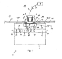
Fig. 1 einen stark schematisierten Schnitt einer Kraftfahrzeugklimaanlage. - Die in
Fig. 1 stark schematisiert dargestellte Kraftfahrzeugklimaanlage 1 umfasst ein Gehäuse 2, in dem ein Luftkanal 13 ausgebildet ist. In dem Luftkanal 13 ist ein Gebläse 12 zum Umwälzen der Luft in dem Luftkanal 13 vorhanden. In Strömungsrichtung nach dem Gebläse 12 ist ein Verdampfer 11 zum Kühlen der Luft und eine elektrische Heizeinrichtung 3 bestehend aus PTC-Heizelementen 4 angeordnet. Die elektrische Heizeinrichtung 3 bzw. die PTC-Heizelemente 4 als elektrische Widerstandselemente erwärmen sich beim Durchleiten von elektrischem Strom. Die PTC-Heizelemente 4 bestehen dabei aus Materialien, die einen elektrischen Widerstand aufweisen und bei tiefen Temperaturen den Strom besser leiten können als bei höheren Temperaturen. Der elektrische Widerstand vergrößert sich somit bei steigender Temperatur, so dass eine Überhitzung der PTC-Heizelemente 4 verhindert werden kann als bei der Verwendung eines normalen Heizelementes (nicht dargestellt), da hier unabhängig von den Randbedingungen, z. B. der Menge der Luft, die an den normalen Heizelementen vorbeigeleitet wird, immer ungefähr der gleiche elektrische Widerstand und dadurch im Wesentlichen die gleiche elektrische Heizleistung aufgebracht wird. Die PTC-Heizelemente 4 werden dabei mit Hochspannung mit einer Spannung im Bereich von ungefähr 300 V betrieben. - Die Kraftfahrzeugklimaanlage 1 dient somit zum Erwärmen und/oder Kühlen von in einen Fahrzeuginnenraum des Kraftfahrzeuges (nicht dargestellt) eingeleiteter Luft. Das Gehäuse 2 der Kraftfahrzeugklimaanlage 1 weist hierzu eine Eintrittsöffnung 20 zum Einleiten von Luft in die Kraftfahrzeugklimaanlage 1 und eine Austrittsöffnung 21 zum Ausleiten der erwärmten und/oder gekühlten Luft aus der Kraftfahrzeugklimaanlage 1 und zum anschließenden Einleiten in den Innenraum des Kraftfahrzeuges auf.
- Optional kann die Kraftfahrzeugklimaanlage 1 auch eine Wärmeübertrager (nicht dargestellt) bzw. einen Wärmetauscher aufweisen, mittels dem zusätzlich zu der elektrischen Heizeinrichtung 3 die durch den Luftkanal 13 geleitete Luft auch durch Abwärme vom Verbrennungsmotor eines Kraftfahrzeuges erwärmt werden kann.
- Innerhalb des Gehäuses 2 der Kraftfahrzeugklimaanlage 1 ist eine Steuerungs- und/oder Regeleinheit 10 für die elektrische Heizeinrichtung 3 angeordnet. Die Steuerungs- und/oder Regeleinheit 10 dient zur Steuerung und/oder Regelung der elektrischen Heizleistung der elektrischen Heizeinrichtung 3. Die Steuerungs- und/oder Regeleinheit 10 kann dabei auch als ein Relais ausgebildet sein. Mittels eines Steuerungskabels 17 wird die Steuerungs- und/oder Regeleinheit 10 von einer übergeordneten Steuerungseinheit der Kraftfahrzeugklimaanlage 1 und/oder des Kraftfahrzeuges gesteuert und/oder geregelt. Innerhalb eines Motorraums 14 des Kraftfahrzeuges ist eine Hochspannungsquelle 9 vorhanden.
- Eine Stirnwandung 15 trennt den Motorraum 14 von einem Raum ab, der gegenüber der Stirnwandung 15 von dem Moorraum 14 abgewandt ist und dabei auch den Innenraum des Kraftfahrzeuges umfasst. In diesem Raum ist die Kraftfahrzeugklimaanlage 1 angeordnet. Die Stirnwandung 15 des Kraftfahrzeuges weist dabei eine Ausnehmung 16 auf. An einer Außenseite des Gehäuses 2 der Kraftfahrzeugklimaanlage 1 ist ein Stecker 5 für Hochspannung mit zwei elektrischen Kontaktelementen 7 befestigt. Eine Gehäusewandung 22 des Gehäuses 2, an welcher der Stecker 5 befestigt ist, ist dabei im Bereich der Stirnwandung 15 angeordnet. Dadurch besteht ein geringer Abstand zwischen der Gehäusewandung 22 und der Stirnwandung 15. Der Stecker 5 durchstößt dabei durch die Ausnehmung 16 die Stirnwandung 15 und ist damit teilweise innerhalb der Ausnehmung 16 angeordnet. Ferner ist ein Teil des Steckers 5 auch innerhalb des Motorraumes 14 positioniert. Ein Gegenstecker 6 mit zwei elektrischen Kontaktelementen 7 ist mittels eines Stromkabels 8 mit einer Hochspannungsquelle 9 im Motorraum 14 elektrisch verbunden. Der Gegenstecker 6, welcher in den Stecker 5 eingesteckt ist, stellt somit eine elektrische Verbindung zwischen dem Stecker 5 mittels den elektrischen Kontaktelementen 7 und des Stromkabels 8 zu der Hochspannungsquelle 9 her. Mittels nicht dargestellter elektrischer Leitungen wird der Strom anschließend von den elektrischen Kontaktelementen 7 des Steckers 5 zu der Steuerung- und/oder Regeleinheit 10 geleitet. Von der Steuerungs- und/oder Regeleinheit 10 führen Stromdrähte 19 zu den PTC-Heizelementen 4. Somit besteht eine elektrisch leitende Verbindung von den PTC-Heizelementen 4 zu der Hochspannungsquelle 9, die von der Steuerungs- und/oder Regeleinheit 10 unterbrochen werden kann.
- Die Steuerungs- und/oder Regeleinheit 10 gibt Abwärme ab. Zum Ableiten dieser Abwärme ist an der Gehäusewandung 22, die sowohl eine Gehäusewandung 22 der Kraftfahrzeugklimaanlage 1 als auch der Steuerungs-und/oder Regeleinheit 10 darstellt, Kühllamellen 18 ausgebildet. Die Größe der Ausnehmung 16 ist dabei geringfügig größer ausgebildet als zur Durchführung des Steckers 5 erforderlich, so dass Abwärme der Steuerungs-und/oder Regeleinheit 10 unmittelbar durch die Ausnehmung 16 von der Gehäusewandung 22 und den Kühllamellen 18 in den Motorraum 14 durch Wärmestrahlung und Wärmekonvektion eingeleitet werden kann. Eine gute und zuverlässige Kühlung der Steuerungs- und/oder Regeleinheit 10 ist damit gewährleistet.
- Bei der Montage der Kraftfahrzeugklimaanlage 1 in einem Kraftfahrzeug wird zunächst die Kraftfahrzeugklimaanlage 1 mit dem an der Gehäusewandung 22 bereits befestigten Stecker 5 mittels nicht dargestellter Fixierungseinrichtungen in dem Raum befestigt, welche an der abgewandten Seite der Stirnwandung 15 zu dem Motorraum 14 beginnt. Dies erfolgt dabei dahingehend, dass bei der Fixierung der Kraftfahrzeugklimaanlage 1 in diesem Raum der Stecker 5 durch die bereits vorhandene Ausnehmung 16 in der Stirnwandung 15 eingeführt wird. Bei der Montage der Kraftfahrzeugklimaanlage 1 in diesem Raum brauchen somit keine zusätzlichen Vorkehrungen zur Verbindung der elektrischen Heizeinrichtung 3 mit der Hochspannungsquelle 9 getroffen werden. Lediglich der bereits vorhandene Stecker 5 auf der Gehäusewandung 22 ist in die bereits vorhandene Ausnehmung 16 der Stirnwandung 15 einzuführen. Nach der Fixierung der Kraftfahrzeugklimaanlage 1 kann in einfacher Weise der Gegenstecker 6 vom Motorraum 14 aus der Gegenstecker 6 in den Stecker 5 eingeführt werden. Damit können im Wesentlichen Montagefehler bei der Herstellung der Hochspannungsverbindung zwischen der Hochspannungsquelle 9 und der elektrischen Heizeinrichtung 3 vermieden werden.
- In einem weiteren nicht dargestellten Ausführungsbeispiel ist der Stecker 5 nicht am Gehäuse 2 bzw. der Gehäusewandung 22 oder in der Nähe der Steuerungs- und/oder Regeleinheit 10 befestigt, sondern lediglich mittels des Stromkabels 8 wird der elektrische Strom vom dem Stecker 5 zu der elektrischen Heizeinrichtung 3 geleitet. Der Stecker 5 kann dabei beispielsweise an der Stirnwandung 15 angeordnet sein, z. B. innerhalb des Motorraumes 14, und das Kabel an dem Stecker 5 wird durch die Stirnwandung 15 zu der elektrischen Heizeinrichtung 3 geführt. Damit kann auch in diesem nicht dargestellten Ausführungsbeispiel der Gegenstecker 6 einfach vom Motorraum 14 aus in den Stecker 5 zur Herstellung der elektrischen Verbindung zwischen der Hochspannungsquelle 9 und der elektrischen Heizeinrichtung 3 eingesteckt werden.
- In einem weiteren nicht dargestellten Ausführungsbeispiel ist der Stecker 5 im Bereich der elektrischen Heizeinrichtung 3 z. B. mit einem Abstand von weniger 10 cm oder 5 cm, ausgebildet. Damit ist nur ein Stromkabel 8 mit einer geringen Länge oder es sind nur Stromdrähte 19 erforderüch zur Leitung des elektrischen Stromes vom Stecker 5 zu der elektrischen Heizeinrichtung 3. Vorzugsweise ist dabei in diesem Ausführungsbeispiel die Kraftfahrzeugklimaanlage 1 ohne der Steuerungs- und/oder Regeleinheit 10 ausgebildet. Für die Anordnung des Steckers 5 bezüglich der Stirnwandung 15 gibt es verschiedene Möglichkeiten in diesem Ausführungsbeispiel. Beispielsweise kann in analoger Weise zu dem ersten Ausführungsbeispiel der Stecker 5 teilweise innerhalb der Ausnehmung 16 in der Stirnwandung 15 positioniert sein.
- Die elektrische Versorgung des Gebläses 12 sowie von Stellmotoren zum Bewegen nicht dargestellter Luftklappen der Kraftfahrzeugklimaanlage 1 erfolgt dabei mittels Niederspannung, z. B. einer Spannung im Bereich von 12 V. Hierzu wird ein nicht dargestellter Kabelbaum vom Motorraum 14 zu dem zum Motorraum 14 abgewandten Raum bezüglich der Stirnwandung 15 durch die Stirnwandung 15 geführt und damit das Gebläse 12 und die Stellmotoren für die nicht dargestellten Luftklappen mit elektrischer Energie versorgt. Mittels des Kabelbaumes (nicht dargestellt) werden außerdem noch weitere Stromverbraucher innerhalb des Fahrzeuginnenraumes, z. B. Beleuchtungseinrichtungen oder ein Radio, mit elektrischer Energie versorgt. Der Stecker und der Gegenstecker 5, 6 dienen damit ausschließlich zur Versorgung der elektrischen Heizeinrichtung 3 mit Hochspannung.
- Insgesamt betrachtet sind mit der erfindungsgemäßen Kraftfahrzeugklimaanlage 1 wesentliche Vorteile verbunden. Die elektrische Heizeinrichtung 3 der Kraftfahrzeugklimaanlage 1 wird mit Hochspannung betrieben. Zur Stromversorgung der elektrischen Heizeinrichtung 3 durch eine in dem Motorraum 14 angeordnete Hochspannungsquelle 9 wird der Stecker 5 und den Gegenstecker 6 im Bereich der Stirnwandung 15 angeordnet. Damit kann bei der Montage der Kraftfahrzeugklimaanlage eine besonders einfache und zuverlässige elektrische Verbindung zwischen der Hochspannungsquelle 9 und der elektrischen Heizeinrichtung 3 hergestellt werden.
-
- 1
- Kraftfahrzeugklimaanlage
- 2
- Gehäuse
- 3
- Elektrische Heizeinrichtung
- 4
- PTC-Heizelement
- 5
- Stecker
- 6
- Gegenstecker
- 7
- Elektrische Kontaktelement
- 8
- Stromkabel
- 9
- Hochspannungsquelle
- 10
- Steuerungs- und/oder Regeleinheit für elektrische Heizeinrichtung
- 11
- Verdampfer
- 12
- Gebläse
- 13
- Luftkanal
- 14
- Motorraum
- 15
- Stirnwand
- 16
- Ausnehmung
- 17
- Steuerungskabel für Steuerungseinheit
- 18
- Kühllamelle
- 19
- Stromdraht
- 20
- Eintrittsöffnung
- 21
- Austrittsöffnung
- 22
- Gehäusewandung
Claims (15)
- Kraftfahrzeugklimaanlage (1), insbesondere für ein Elektro- oder Hybridfahrzeug, umfassend- ein Gehäuse (2),- vorzugsweise wenigstens einen Luftkanal (13),- vorzugsweise ein Gebläse (12) zum Umwälzen von Luft und- wenigstens eine mit Hochspannung betriebene elektrische Heizeinrichtung (3),
dadurch gekennzeichnet, dass
ein Stecker (5) für Hochspannung mit wenigstens einem elektrischen Kontaktelement (7) im Bereich einer Stirnwandung (15) eines Kraftfahrzeuges angeordnet ist und der Stecker (5) zum elektrischen Verbinden der elektrischen Heizeinrichtung (3) mit einer Hochspannungsstromquelle (9) dient. - Kraftfahrzeugklimaanlage nach Anspruch 1, dadurch gekennzeichnet, dass der Stecker (5) für Hochspannung einen Abstand von weniger als 20 cm, 10 cm, 5 cm oder 2 cm zu der Stirnwandung (15) aufweist und/oder der Stecker (5) für Hochspannung an der Stirnwandung (15) angeordnet ist und/oder der Stecker (5) an der Stirnwandung (15) mittelbar oder unmittelbar fixiert ist.
- Kraftfahrzeugklimaanlage nach Anspruch 1 oder 2, dadurch gekennzeichnet, dass die Stirnwandung (15) eine Ausnehmung (16) aufweist und der Stecker (5) für Hochspannung in oder an der Ausnehmung (16) angeordnet ist.
- Kraftfahrzeugklimaanlage nach einem oder mehreren der vorhergehenden Ansprüche, dadurch gekennzeichnet, dass die Stecker (5) für Hochspannung an einem Gehäuse (2) der Kraftfahrzeugklimaanlage (1) befestigt ist.
- Kraftfahrzeugklimaanlage nach Anspruch 4, dadurch gekennzeichnet, dass das Gehäuse (2) ein Gehäuse (2) zur Aufnahme einer Steuerungs- und/oder Regeleinheit (10) für die elektrische Heizeinrichtung (3) ist.
- Kraftfahrzeugklimaanlage nach Anspruch 5, dadurch gekennzeichnet, dass Abwärme der Steuerungs- und/oder Regeleinheit (10) durch das Gehäuse (2) und unmittelbar durch die Ausnehmung (16) in der Stirnwandung (15) in einen Motorraum (14) des Kraftfahrzeuges einleitbar ist.
- Kraftfahrzeugklimaanlage nach einem oder mehreren der vorhergehenden Ansprüche, dadurch gekennzeichnet, dass der Stecker (5) für Hochspannung mit einem Stromkabel (8) verbunden ist zur Leitung des elektrischen Stromes zu der elektrischen Heizeinrichtung (3).
- Kraftfahrzeugklimaanlage nach einem oder mehreren der vorhergehenden Ansprüche, dadurch gekennzeichnet, dass die Stecker (5) für Hochspannung mit der elektrischen Heizeinrichtung (3) mechanisch verbunden ist.
- Kraftfahrzeugklimaanlage nach einem oder mehreren der vorhergehenden Ansprüchen, dadurch gekennzeichnet, dass die Kraftfahrzeugklimaanlage (1) einen Gegenstecker (6) für Hochspannung umfasst zum Einstecken in den Stecker (5) für Hochspannung und insbesondere der Gegenstecker (6) für Hochspannung mit dem Stromkabel (8) mit der Hochspannungsquelle (9) verbunden ist.
- Kraftfahrzeugklimaanlage nach Anspruch 9, dadurch gekennzeichnet, dass der Gegenstecker (6) für Hochspannung im Bereich einer Stirnwandung (15) des Kraftfahrzeuges angeordnet ist.
- Kraftfahrzeugklimaanlage nach Anspruch 10, dadurch gekennzeichnet, dass der Gegenstecker (6) für Hochspannung einen Abstand von weniger als 20 cm, 10 cm, 5 cm oder 2 cm zu der Stirnwandung (15) aufweist und/oder der Gegenstecker (6) für Hochspannung an der Stirnwandung (15) angeordnet ist und/oder der Gegenstecker (6) für Hochspannung an der Stirnwandung (15) mittelbar oder unmittelbar fixiert ist.
- Kraftfahrzeugklimaanlage nach Anspruch 10 oder 11, dadurch gekennzeichnet, dass der Gegenstecker (6) für Hochspannung in oder an der Ausnehmung (16) der Stirnwandung (15) angeordnet ist.
- Kraftfahrzeugklimaanlage nach einem oder mehreren der vorhergehenden Ansprüche, dadurch gekennzeichnet, dass die elektrische Heizeinrichtung (3) wenigstens ein PTC-Heizelement (4) ist.
- Kraftfahrzeugklimaanlage nach einem oder mehreren der vorhergehenden Ansprüche, dadurch gekennzeichnet, dass die Spannung der Hochspannung zur Energieversorgung der elektrischen Heizeinrichtung (3) mit elektrischen Strom wenigstens 40 V, 60 V, 110 V, 220 V, 400 V, 600 V oder 1000 V beträgt.
- Kraftfahrzeugklimaanlage nach einem oder mehreren der vorhergehenden Ansprüche, dadurch gekennzeichnet, dass die Kraftfahrzeugklimaanlage (1) nur einen Stecker (5) und/oder nur eine Gegenstecker (6) für Hochspannung zur Versorgung der elektrischen Heizeinrichtung (3) mit elektrischem Strom aufweist.
Priority Applications (1)
| Application Number | Priority Date | Filing Date | Title |
|---|---|---|---|
| EP09290569A EP2275292B1 (de) | 2009-07-17 | 2009-07-17 | Kraftfahrzeug mit Klimaanlage |
Applications Claiming Priority (1)
| Application Number | Priority Date | Filing Date | Title |
|---|---|---|---|
| EP09290569A EP2275292B1 (de) | 2009-07-17 | 2009-07-17 | Kraftfahrzeug mit Klimaanlage |
Publications (2)
| Publication Number | Publication Date |
|---|---|
| EP2275292A1 true EP2275292A1 (de) | 2011-01-19 |
| EP2275292B1 EP2275292B1 (de) | 2013-01-02 |
Family
ID=41279502
Family Applications (1)
| Application Number | Title | Priority Date | Filing Date |
|---|---|---|---|
| EP09290569A Not-in-force EP2275292B1 (de) | 2009-07-17 | 2009-07-17 | Kraftfahrzeug mit Klimaanlage |
Country Status (1)
| Country | Link |
|---|---|
| EP (1) | EP2275292B1 (de) |
Cited By (1)
| Publication number | Priority date | Publication date | Assignee | Title |
|---|---|---|---|---|
| CN118380734A (zh) * | 2024-06-25 | 2024-07-23 | 宁德时代新能源科技股份有限公司 | 电池单体、电池及用电设备 |
Citations (4)
| Publication number | Priority date | Publication date | Assignee | Title |
|---|---|---|---|---|
| DE7436282U (de) * | 1974-10-30 | 1975-08-21 | Bender W Ohg | Elektrisches Autoheizgerät |
| DE10344704A1 (de) | 2003-09-26 | 2005-06-09 | Bayerische Motoren Werke Ag | Einbaumodul für einen Durchlass in einer Stirnwand einer Fahrgastzelle |
| EP1580050A1 (de) * | 2004-03-26 | 2005-09-28 | Behr GmbH & Co. KG | Elektrische Zusatzheizungseinrichtung, insbesondere für ein Kraftfahrzeug |
| GB2443225A (en) * | 2006-10-25 | 2008-04-30 | Elite Automotive Systems Ltd | A heater for an electric vehicle |
-
2009
- 2009-07-17 EP EP09290569A patent/EP2275292B1/de not_active Not-in-force
Patent Citations (4)
| Publication number | Priority date | Publication date | Assignee | Title |
|---|---|---|---|---|
| DE7436282U (de) * | 1974-10-30 | 1975-08-21 | Bender W Ohg | Elektrisches Autoheizgerät |
| DE10344704A1 (de) | 2003-09-26 | 2005-06-09 | Bayerische Motoren Werke Ag | Einbaumodul für einen Durchlass in einer Stirnwand einer Fahrgastzelle |
| EP1580050A1 (de) * | 2004-03-26 | 2005-09-28 | Behr GmbH & Co. KG | Elektrische Zusatzheizungseinrichtung, insbesondere für ein Kraftfahrzeug |
| GB2443225A (en) * | 2006-10-25 | 2008-04-30 | Elite Automotive Systems Ltd | A heater for an electric vehicle |
Cited By (1)
| Publication number | Priority date | Publication date | Assignee | Title |
|---|---|---|---|---|
| CN118380734A (zh) * | 2024-06-25 | 2024-07-23 | 宁德时代新能源科技股份有限公司 | 电池单体、电池及用电设备 |
Also Published As
| Publication number | Publication date |
|---|---|
| EP2275292B1 (de) | 2013-01-02 |
Similar Documents
| Publication | Publication Date | Title |
|---|---|---|
| EP2646268B1 (de) | Kraftfahrzeugklimaanlage | |
| EP2299201B1 (de) | Elektrische Heizvorrichtung | |
| EP3295509B1 (de) | Energiespeicher eines kraftfahrzeugs | |
| EP2299200B1 (de) | Elektrische Heizvorrichtung | |
| DE102009057870B4 (de) | Kraftfahrzeugklimaanlage | |
| DE102010056204A1 (de) | Temperierelement für eine Batterie | |
| DE112013002131B4 (de) | Heizapparat | |
| EP2863143B1 (de) | Heizvorrichtung | |
| EP2609376A2 (de) | Elektrische fahrzeug-heizvorrichtung | |
| EP2131117B1 (de) | Kraftfahrzeugklimaanlage mit PTC-Heizeinrichtung | |
| DE112017004627T5 (de) | Wechselrichter-integrierter elektrischer Kompressor und Verfahren zum Herstellen desselben | |
| EP2275292B1 (de) | Kraftfahrzeug mit Klimaanlage | |
| DE102018203538A1 (de) | Fahrzeug mit zumindest einem elektrochemischen Energiespeicher | |
| EP2346304A1 (de) | Wärmeübertrager | |
| EP2395296A1 (de) | Wärmeübertrager | |
| DE10121906B4 (de) | Belüftungsvorrichtung für Fahrzeuge | |
| EP2505396B1 (de) | Kraftfahrzeugklimaanlage | |
| EP1870288B1 (de) | Kabelbaum mit Kühlung | |
| EP2168794B1 (de) | Elektrisches Heizsystem und Verfahren zur stufenlosen Ansteuerung einer elektrischen Heizeinrichtung | |
| DE102009053548A1 (de) | Kühlerzargensystem | |
| EP1992801A2 (de) | Kraftfahrzeug mit linear geregeltem Motorgebläse | |
| EP2570279A1 (de) | Kraftfahrzeugklimaanlage | |
| EP1580050A1 (de) | Elektrische Zusatzheizungseinrichtung, insbesondere für ein Kraftfahrzeug | |
| DE19854119A1 (de) | Heizungsanlage für den Innenraum eines Fahrzeuges | |
| EP4678462A1 (de) | Kühlsystem zum kühlen von fahrzeugkomponenten eines batterieelektrisch betriebenen fahrzeugs sowie fahrzeug mit zumindest einem solchen kühlsystem |
Legal Events
| Date | Code | Title | Description |
|---|---|---|---|
| PUAI | Public reference made under article 153(3) epc to a published international application that has entered the european phase |
Free format text: ORIGINAL CODE: 0009012 |
|
| AK | Designated contracting states |
Kind code of ref document: A1 Designated state(s): AT BE BG CH CY CZ DE DK EE ES FI FR GB GR HR HU IE IS IT LI LT LU LV MC MK MT NL NO PL PT RO SE SI SK SM TR |
|
| AX | Request for extension of the european patent |
Extension state: AL BA RS |
|
| 17P | Request for examination filed |
Effective date: 20110719 |
|
| 17Q | First examination report despatched |
Effective date: 20110812 |
|
| GRAP | Despatch of communication of intention to grant a patent |
Free format text: ORIGINAL CODE: EPIDOSNIGR1 |
|
| GRAS | Grant fee paid |
Free format text: ORIGINAL CODE: EPIDOSNIGR3 |
|
| GRAA | (expected) grant |
Free format text: ORIGINAL CODE: 0009210 |
|
| AK | Designated contracting states |
Kind code of ref document: B1 Designated state(s): AT BE BG CH CY CZ DE DK EE ES FI FR GB GR HR HU IE IS IT LI LT LU LV MC MK MT NL NO PL PT RO SE SI SK SM TR |
|
| REG | Reference to a national code |
Ref country code: GB Ref legal event code: FG4D Free format text: NOT ENGLISH |
|
| REG | Reference to a national code |
Ref country code: AT Ref legal event code: REF Ref document number: 591386 Country of ref document: AT Kind code of ref document: T Effective date: 20130115 Ref country code: CH Ref legal event code: EP |
|
| REG | Reference to a national code |
Ref country code: IE Ref legal event code: FG4D Free format text: LANGUAGE OF EP DOCUMENT: GERMAN |
|
| REG | Reference to a national code |
Ref country code: DE Ref legal event code: R096 Ref document number: 502009005871 Country of ref document: DE Effective date: 20130307 |
|
| REG | Reference to a national code |
Ref country code: NL Ref legal event code: VDEP Effective date: 20130102 |
|
| PG25 | Lapsed in a contracting state [announced via postgrant information from national office to epo] |
Ref country code: SI Free format text: LAPSE BECAUSE OF FAILURE TO SUBMIT A TRANSLATION OF THE DESCRIPTION OR TO PAY THE FEE WITHIN THE PRESCRIBED TIME-LIMIT Effective date: 20130102 |
|
| REG | Reference to a national code |
Ref country code: LT Ref legal event code: MG4D |
|
| PG25 | Lapsed in a contracting state [announced via postgrant information from national office to epo] |
Ref country code: NO Free format text: LAPSE BECAUSE OF FAILURE TO SUBMIT A TRANSLATION OF THE DESCRIPTION OR TO PAY THE FEE WITHIN THE PRESCRIBED TIME-LIMIT Effective date: 20130402 Ref country code: LT Free format text: LAPSE BECAUSE OF FAILURE TO SUBMIT A TRANSLATION OF THE DESCRIPTION OR TO PAY THE FEE WITHIN THE PRESCRIBED TIME-LIMIT Effective date: 20130102 Ref country code: BG Free format text: LAPSE BECAUSE OF FAILURE TO SUBMIT A TRANSLATION OF THE DESCRIPTION OR TO PAY THE FEE WITHIN THE PRESCRIBED TIME-LIMIT Effective date: 20130402 Ref country code: CZ Free format text: LAPSE BECAUSE OF FAILURE TO SUBMIT A TRANSLATION OF THE DESCRIPTION OR TO PAY THE FEE WITHIN THE PRESCRIBED TIME-LIMIT Effective date: 20130102 Ref country code: SE Free format text: LAPSE BECAUSE OF FAILURE TO SUBMIT A TRANSLATION OF THE DESCRIPTION OR TO PAY THE FEE WITHIN THE PRESCRIBED TIME-LIMIT Effective date: 20130102 Ref country code: ES Free format text: LAPSE BECAUSE OF FAILURE TO SUBMIT A TRANSLATION OF THE DESCRIPTION OR TO PAY THE FEE WITHIN THE PRESCRIBED TIME-LIMIT Effective date: 20130413 Ref country code: IS Free format text: LAPSE BECAUSE OF FAILURE TO SUBMIT A TRANSLATION OF THE DESCRIPTION OR TO PAY THE FEE WITHIN THE PRESCRIBED TIME-LIMIT Effective date: 20130502 |
|
| PG25 | Lapsed in a contracting state [announced via postgrant information from national office to epo] |
Ref country code: PL Free format text: LAPSE BECAUSE OF FAILURE TO SUBMIT A TRANSLATION OF THE DESCRIPTION OR TO PAY THE FEE WITHIN THE PRESCRIBED TIME-LIMIT Effective date: 20130102 Ref country code: PT Free format text: LAPSE BECAUSE OF FAILURE TO SUBMIT A TRANSLATION OF THE DESCRIPTION OR TO PAY THE FEE WITHIN THE PRESCRIBED TIME-LIMIT Effective date: 20130502 Ref country code: LV Free format text: LAPSE BECAUSE OF FAILURE TO SUBMIT A TRANSLATION OF THE DESCRIPTION OR TO PAY THE FEE WITHIN THE PRESCRIBED TIME-LIMIT Effective date: 20130102 Ref country code: FI Free format text: LAPSE BECAUSE OF FAILURE TO SUBMIT A TRANSLATION OF THE DESCRIPTION OR TO PAY THE FEE WITHIN THE PRESCRIBED TIME-LIMIT Effective date: 20130102 Ref country code: NL Free format text: LAPSE BECAUSE OF FAILURE TO SUBMIT A TRANSLATION OF THE DESCRIPTION OR TO PAY THE FEE WITHIN THE PRESCRIBED TIME-LIMIT Effective date: 20130102 Ref country code: GR Free format text: LAPSE BECAUSE OF FAILURE TO SUBMIT A TRANSLATION OF THE DESCRIPTION OR TO PAY THE FEE WITHIN THE PRESCRIBED TIME-LIMIT Effective date: 20130403 |
|
| PG25 | Lapsed in a contracting state [announced via postgrant information from national office to epo] |
Ref country code: HR Free format text: LAPSE BECAUSE OF FAILURE TO SUBMIT A TRANSLATION OF THE DESCRIPTION OR TO PAY THE FEE WITHIN THE PRESCRIBED TIME-LIMIT Effective date: 20130102 |
|
| PG25 | Lapsed in a contracting state [announced via postgrant information from national office to epo] |
Ref country code: DK Free format text: LAPSE BECAUSE OF FAILURE TO SUBMIT A TRANSLATION OF THE DESCRIPTION OR TO PAY THE FEE WITHIN THE PRESCRIBED TIME-LIMIT Effective date: 20130102 Ref country code: EE Free format text: LAPSE BECAUSE OF FAILURE TO SUBMIT A TRANSLATION OF THE DESCRIPTION OR TO PAY THE FEE WITHIN THE PRESCRIBED TIME-LIMIT Effective date: 20130102 Ref country code: RO Free format text: LAPSE BECAUSE OF FAILURE TO SUBMIT A TRANSLATION OF THE DESCRIPTION OR TO PAY THE FEE WITHIN THE PRESCRIBED TIME-LIMIT Effective date: 20130102 Ref country code: SK Free format text: LAPSE BECAUSE OF FAILURE TO SUBMIT A TRANSLATION OF THE DESCRIPTION OR TO PAY THE FEE WITHIN THE PRESCRIBED TIME-LIMIT Effective date: 20130102 |
|
| PLBE | No opposition filed within time limit |
Free format text: ORIGINAL CODE: 0009261 |
|
| STAA | Information on the status of an ep patent application or granted ep patent |
Free format text: STATUS: NO OPPOSITION FILED WITHIN TIME LIMIT |
|
| PG25 | Lapsed in a contracting state [announced via postgrant information from national office to epo] |
Ref country code: CY Free format text: LAPSE BECAUSE OF FAILURE TO SUBMIT A TRANSLATION OF THE DESCRIPTION OR TO PAY THE FEE WITHIN THE PRESCRIBED TIME-LIMIT Effective date: 20130102 |
|
| 26N | No opposition filed |
Effective date: 20131003 |
|
| PG25 | Lapsed in a contracting state [announced via postgrant information from national office to epo] |
Ref country code: IT Free format text: LAPSE BECAUSE OF FAILURE TO SUBMIT A TRANSLATION OF THE DESCRIPTION OR TO PAY THE FEE WITHIN THE PRESCRIBED TIME-LIMIT Effective date: 20130102 |
|
| REG | Reference to a national code |
Ref country code: DE Ref legal event code: R097 Ref document number: 502009005871 Country of ref document: DE Effective date: 20131003 |
|
| BERE | Be: lapsed |
Owner name: BEHR FRANCE ROUFFACH SAS Effective date: 20130731 |
|
| PG25 | Lapsed in a contracting state [announced via postgrant information from national office to epo] |
Ref country code: MC Free format text: LAPSE BECAUSE OF FAILURE TO SUBMIT A TRANSLATION OF THE DESCRIPTION OR TO PAY THE FEE WITHIN THE PRESCRIBED TIME-LIMIT Effective date: 20130102 |
|
| REG | Reference to a national code |
Ref country code: CH Ref legal event code: PL |
|
| GBPC | Gb: european patent ceased through non-payment of renewal fee |
Effective date: 20130717 |
|
| REG | Reference to a national code |
Ref country code: IE Ref legal event code: MM4A |
|
| PG25 | Lapsed in a contracting state [announced via postgrant information from national office to epo] |
Ref country code: GB Free format text: LAPSE BECAUSE OF NON-PAYMENT OF DUE FEES Effective date: 20130717 Ref country code: LI Free format text: LAPSE BECAUSE OF NON-PAYMENT OF DUE FEES Effective date: 20130731 Ref country code: BE Free format text: LAPSE BECAUSE OF NON-PAYMENT OF DUE FEES Effective date: 20130731 Ref country code: CH Free format text: LAPSE BECAUSE OF NON-PAYMENT OF DUE FEES Effective date: 20130731 |
|
| PG25 | Lapsed in a contracting state [announced via postgrant information from national office to epo] |
Ref country code: IE Free format text: LAPSE BECAUSE OF NON-PAYMENT OF DUE FEES Effective date: 20130717 |
|
| PG25 | Lapsed in a contracting state [announced via postgrant information from national office to epo] |
Ref country code: SM Free format text: LAPSE BECAUSE OF FAILURE TO SUBMIT A TRANSLATION OF THE DESCRIPTION OR TO PAY THE FEE WITHIN THE PRESCRIBED TIME-LIMIT Effective date: 20130102 |
|
| PG25 | Lapsed in a contracting state [announced via postgrant information from national office to epo] |
Ref country code: MT Free format text: LAPSE BECAUSE OF FAILURE TO SUBMIT A TRANSLATION OF THE DESCRIPTION OR TO PAY THE FEE WITHIN THE PRESCRIBED TIME-LIMIT Effective date: 20130102 Ref country code: TR Free format text: LAPSE BECAUSE OF FAILURE TO SUBMIT A TRANSLATION OF THE DESCRIPTION OR TO PAY THE FEE WITHIN THE PRESCRIBED TIME-LIMIT Effective date: 20130102 |
|
| PG25 | Lapsed in a contracting state [announced via postgrant information from national office to epo] |
Ref country code: MK Free format text: LAPSE BECAUSE OF FAILURE TO SUBMIT A TRANSLATION OF THE DESCRIPTION OR TO PAY THE FEE WITHIN THE PRESCRIBED TIME-LIMIT Effective date: 20130102 Ref country code: HU Free format text: LAPSE BECAUSE OF FAILURE TO SUBMIT A TRANSLATION OF THE DESCRIPTION OR TO PAY THE FEE WITHIN THE PRESCRIBED TIME-LIMIT; INVALID AB INITIO Effective date: 20090717 Ref country code: LU Free format text: LAPSE BECAUSE OF NON-PAYMENT OF DUE FEES Effective date: 20130717 |
|
| REG | Reference to a national code |
Ref country code: DE Ref legal event code: R082 Ref document number: 502009005871 Country of ref document: DE Representative=s name: GRAUEL, ANDREAS, DIPL.-PHYS. DR. RER. NAT., DE Ref country code: DE Ref legal event code: R081 Ref document number: 502009005871 Country of ref document: DE Owner name: MAHLE INTERNATIONAL GMBH, DE Free format text: FORMER OWNER: BEHR FRANCE ROUFFACH SAS, ROUFFACH, FR |
|
| REG | Reference to a national code |
Ref country code: AT Ref legal event code: MM01 Ref document number: 591386 Country of ref document: AT Kind code of ref document: T Effective date: 20140717 |
|
| PG25 | Lapsed in a contracting state [announced via postgrant information from national office to epo] |
Ref country code: AT Free format text: LAPSE BECAUSE OF NON-PAYMENT OF DUE FEES Effective date: 20140717 |
|
| REG | Reference to a national code |
Ref country code: FR Ref legal event code: PLFP Year of fee payment: 8 |
|
| REG | Reference to a national code |
Ref country code: FR Ref legal event code: PLFP Year of fee payment: 9 |
|
| REG | Reference to a national code |
Ref country code: FR Ref legal event code: PLFP Year of fee payment: 10 |
|
| PGFP | Annual fee paid to national office [announced via postgrant information from national office to epo] |
Ref country code: PT Payment date: 20181217 Year of fee payment: 4 |
|
| PG25 | Lapsed in a contracting state [announced via postgrant information from national office to epo] |
Ref country code: FR Free format text: LAPSE BECAUSE OF NON-PAYMENT OF DUE FEES Effective date: 20190731 |
|
| PGFP | Annual fee paid to national office [announced via postgrant information from national office to epo] |
Ref country code: DE Payment date: 20210920 Year of fee payment: 13 |
|
| REG | Reference to a national code |
Ref country code: DE Ref legal event code: R119 Ref document number: 502009005871 Country of ref document: DE |
|
| PG25 | Lapsed in a contracting state [announced via postgrant information from national office to epo] |
Ref country code: DE Free format text: LAPSE BECAUSE OF NON-PAYMENT OF DUE FEES Effective date: 20230201 |