EP2275221A2 - Schweißvorrichtung - Google Patents
Schweißvorrichtung Download PDFInfo
- Publication number
- EP2275221A2 EP2275221A2 EP10075268A EP10075268A EP2275221A2 EP 2275221 A2 EP2275221 A2 EP 2275221A2 EP 10075268 A EP10075268 A EP 10075268A EP 10075268 A EP10075268 A EP 10075268A EP 2275221 A2 EP2275221 A2 EP 2275221A2
- Authority
- EP
- European Patent Office
- Prior art keywords
- welding
- cooling
- welding torch
- air
- supply line
- Prior art date
- Legal status (The legal status is an assumption and is not a legal conclusion. Google has not performed a legal analysis and makes no representation as to the accuracy of the status listed.)
- Withdrawn
Links
Images

Classifications
-
- B—PERFORMING OPERATIONS; TRANSPORTING
- B23—MACHINE TOOLS; METAL-WORKING NOT OTHERWISE PROVIDED FOR
- B23K—SOLDERING OR UNSOLDERING; WELDING; CLADDING OR PLATING BY SOLDERING OR WELDING; CUTTING BY APPLYING HEAT LOCALLY, e.g. FLAME CUTTING; WORKING BY LASER BEAM
- B23K9/00—Arc welding or cutting
- B23K9/24—Features related to electrodes
- B23K9/28—Supporting devices for electrodes
- B23K9/285—Cooled electrode holders
-
- B—PERFORMING OPERATIONS; TRANSPORTING
- B23—MACHINE TOOLS; METAL-WORKING NOT OTHERWISE PROVIDED FOR
- B23K—SOLDERING OR UNSOLDERING; WELDING; CLADDING OR PLATING BY SOLDERING OR WELDING; CUTTING BY APPLYING HEAT LOCALLY, e.g. FLAME CUTTING; WORKING BY LASER BEAM
- B23K9/00—Arc welding or cutting
- B23K9/32—Accessories
Definitions
- the present invention relates to a welding device consisting of a housing to which a welding torch is connected via a supply line, which housing comprises cooling means which pass a cooling medium to the welding torch via the supply line.
- a welding device of this type is known, for example, from Netherlands patent 1027088 in the name of the Applicant.
- the welding torch is cooled by means of recirculating cooling water.
- a circuit for cooling water is present, which circuit comprises a heat exchanger, a pump and a storage vessel for water, which are accommodated in the housing.
- the water is taken to the welding torch via the supply line and returned to the housing from the welding torch via the supply line.
- the cooling means are formed by a compressor which draws in outside air and is connected to a pressure line which passes this air through the supply line via a cooling unit to the welding torch in order to cool the latter, and returns the air from the welding torch via the supply line to a discharge means which is arranged outside the supply line at some distance from the welding torch, the welding torch being provided with means to assist the heat transfer from the torch to the cooling air.
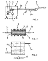
- Fig. 1 diagrammatically shows a welding device according to the invention which consists of a housing 1, to which a welding torch 3 is connected via a supply line 2.
- the housing 1 is provided in the customary manner with a stock roll of welding wire (not shown) and a gas supply (not shown either), with the welding wire and the gas being passed to the welding torch via the supply line.
- the housing 1 also contains cooling means for cooling the welding torch 3. These cooling means are formed by a compressor 4 which is accommodated in the housing 1 and draws in outside air, and which cooled air is then passed through a cooling unit 6 via a pressure line 5.
- the pressure line 5a runs from the cooling unit via the supply line to the welding torch 3 in order to cool the latter.
- the pressure line 5b returns via the supply line 2 and ends at some distance from the welding torch outside the supply line at a discharge means, like a throttle member 7, in order to maintain the pressure in the pressure line.
- the cooling unit consists of a central block 8 made of aluminium or another suitable metal, in which a zigzag-shaped duct is provided which is indicated by dashed lines in Fig. 3 .
- the pressure line 5 coming from the compressor is connected to one side of this duct, while the pressure line 5a running to the welding torch 3 is connected to the other side thereof.
- the opposite large lateral surfaces of the block 8 are covered by thermoelectric elements 9, also referred to as Peltier elements.
- Such a Peltier element which is in the form of a flat rectangular panel, has the property that when a direct current is applied thereto, it acts as a heat pump, with the heat being conveyed from the one large lateral surface to the other large lateral surface. This results in one lateral surface cooling down while the other lateral surface heats up.
- Such Peltier elements are generally known and are commonly used for cooling purposes.
- a number of such Peltier elements are arranged on each side of said block 8, in such a manner that they adjoin the central block 8 with the side which is cooling down.
- a plate 10 with cooling ribs is arranged against the side of the Peltier elements which heats up in order to dissipate the heat.
- the central block 8 is thus enclosed by the Peltier elements which are connected in parallel and are fed by means of a direct current source 11.
- the block 8 is thus cooled, the heat being dissipated by means of the plates 10 comprising cooling ribs.
- a fan 12 may also be provided in the housing 1 in order to assist the heat dissipation via the cooling ribs.
- Fig. 3 shows a side view of the cooling unit in which the plate 10 comprising cooling ribs has been omitted.
- the plate 10 comprising cooling ribs has been omitted.
- nine Peltier elements are arranged on each large lateral surface of the block 8.
- Such a cooling unit is very reliable and low-maintenance, since it does not contain any moving parts.
- the unit is furthermore able to cool down the air to below zero degrees Celsius.
- This cooled air is supplied via the welding torch, the welding torch being provided with means to increase the transfer of heat from the welding torch to the air.
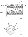
- Fig. 4 diagrammatically shows a part of a cooling jacket of the welding torch 3 in cross section.
- This jacket comprises a protective tube 14 inside of which a tube 15 is arranged which is provided on the outside with a double trapezium-shaped screw thread. Together with the protective tube, this screw thread forms two parallel helical ducts which are in communication with one another at that end of the jacket which is situated closest to the welding mouth of the torch, i.e. the righthand side end in the drawing, so that one continuous duct is formed comprising an outgoing duct part and a returning duct part.
- the cold air flows through the jacket via the outgoing duct part and returns through the jacket again via the returning duct part while absorbing the heat from the welding torch.
- the path of the air in the cooling jacket is indicated by dashed lines.
- the heated air leaves the device via the throttle member 7 in order to keep the pressure of the cooling air in the pressure line 5, 5a, 5b at a desired value.
- Fig. 5 shows a cross section of the supply line 2 which is in the form of a coaxial cable having a central passage 13 for supplying the welding wire and the protective gas, while the pressure line 5a for supplying the cooling air and the line 5b for discharging the cooling air which has heated up can be seen in the wall.
- FIG. 6 shows a further development of the invention, in which the cooling air flowing out of the line 5b is effectively used for discharging welding fumes, which originate near the mouth of the welding torch 3.
- a hood 20 has been arranged on said welding torch, said hood having an inlet opening 20a near the mouth of the welding torch and is connected at the other end to a discharge line 21.
- Said discharge line ends at some distance from the welding torch in a chamber 22 having an outlet opening 23.
- the line 5b for discharging the cooling air, which has been warmed up, ends also in the chamber 22.
- the discharge means 7 of the line 5b in this case exist of a nozzle 7a, so that the cooling air, being warmed up, is flowing out said nozzle with a high velocity.
- the hood 20 can be arranged on the welding torch in a removable and/or displaceable way, in order not to obstruct the welding process in some cases.
Landscapes
- Engineering & Computer Science (AREA)
- Physics & Mathematics (AREA)
- Plasma & Fusion (AREA)
- Mechanical Engineering (AREA)
- Arc Welding In General (AREA)
Applications Claiming Priority (1)
| Application Number | Priority Date | Filing Date | Title |
|---|---|---|---|
| NL1037086A NL1037086C2 (nl) | 2009-06-30 | 2009-06-30 | Lasinrichting. |
Publications (2)
| Publication Number | Publication Date |
|---|---|
| EP2275221A2 true EP2275221A2 (de) | 2011-01-19 |
| EP2275221A3 EP2275221A3 (de) | 2011-06-29 |
Family
ID=41667808
Family Applications (1)
| Application Number | Title | Priority Date | Filing Date |
|---|---|---|---|
| EP10075268A Withdrawn EP2275221A3 (de) | 2009-06-30 | 2010-06-23 | Schweißvorrichtung |
Country Status (2)
| Country | Link |
|---|---|
| EP (1) | EP2275221A3 (de) |
| NL (1) | NL1037086C2 (de) |
Cited By (1)
| Publication number | Priority date | Publication date | Assignee | Title |
|---|---|---|---|---|
| US11700682B2 (en) | 2019-07-16 | 2023-07-11 | The Esab Group, Inc. | Thermoelectric cooling of consumables in a plasma torch |
Citations (1)
| Publication number | Priority date | Publication date | Assignee | Title |
|---|---|---|---|---|
| NL1027088C1 (nl) | 2004-09-22 | 2006-03-27 | Hans Van De Ven | Lasinrichting. |
Family Cites Families (5)
| Publication number | Priority date | Publication date | Assignee | Title |
|---|---|---|---|---|
| FR2540978B1 (fr) * | 1983-02-11 | 1987-12-18 | Realisa Aerothermiques Et | Dispositif de climatisation et engin de transport muni d'un tel dispositif |
| US5121788A (en) * | 1989-10-16 | 1992-06-16 | Miller Electric Mfg. Co. | Self contained heat exchange apparatus |
| US5248868A (en) * | 1992-05-22 | 1993-09-28 | Cusick Iii Joseph B | Melding gun |
| US5669556A (en) * | 1994-07-06 | 1997-09-23 | Exedy Corporation | Nozzle for a welding torch having sputter build-up reducing configuration |
| US20050016978A1 (en) * | 2003-07-23 | 2005-01-27 | Stein Alan E. | Method and apparatus to adaptively cool a welding-type system |
-
2009
- 2009-06-30 NL NL1037086A patent/NL1037086C2/nl not_active IP Right Cessation
-
2010
- 2010-06-23 EP EP10075268A patent/EP2275221A3/de not_active Withdrawn
Patent Citations (1)
| Publication number | Priority date | Publication date | Assignee | Title |
|---|---|---|---|---|
| NL1027088C1 (nl) | 2004-09-22 | 2006-03-27 | Hans Van De Ven | Lasinrichting. |
Cited By (1)
| Publication number | Priority date | Publication date | Assignee | Title |
|---|---|---|---|---|
| US11700682B2 (en) | 2019-07-16 | 2023-07-11 | The Esab Group, Inc. | Thermoelectric cooling of consumables in a plasma torch |
Also Published As
| Publication number | Publication date |
|---|---|
| EP2275221A3 (de) | 2011-06-29 |
| NL1037086C2 (nl) | 2011-01-04 |
Similar Documents
| Publication | Publication Date | Title |
|---|---|---|
| CN106576436B (zh) | 多模式冷却设备 | |
| DE102016001966B4 (de) | Luftgekühlte Laservorrichtung mit Kühlrippen aufweisendem Wärmeübertragungsbauteil | |
| JP2009516249A (ja) | 熱交換器及びネットワークキャビネット除熱方法 | |
| KR20170031690A (ko) | 강력한 중복 가능 누설-방지성의 냉각 엔클러져 벽 | |
| BR112018013629B1 (pt) | Trocador de calor evaporativo para resfriar ou condensar um fluido de processo | |
| US20070295492A1 (en) | Heat exchange system with inclined heat exchanger device | |
| CN107002712A (zh) | 用于液压机组的冷却装置和冷却装置的使用 | |
| GB2563056A (en) | Heat exchanger | |
| DE202019100059U1 (de) | Inverteranordnung | |
| US20170181317A1 (en) | Liquid-cooling heat sink | |
| JP6555081B2 (ja) | 密閉ループ循環液冷装置及び電子機器 | |
| US9883608B2 (en) | Cooling device for cooling a switchgear cabinet | |
| EP2275221A2 (de) | Schweißvorrichtung | |
| RU2515530C2 (ru) | Устройство кондиционирования для охлаждения воздуха в шкафу для электронных устройств | |
| KR20150103627A (ko) | 열교환형 전력소자 모듈을 사용한 전력 변환장치 | |
| EP3081883A1 (de) | Rohrstruktur, kühlvorrichtung damit und kältemitteldampftransportverfahren | |
| US20200232689A1 (en) | Condenser | |
| JP6462709B2 (ja) | 冷却システム及び電子装置 | |
| US10160545B2 (en) | Ram air heat exchanger | |
| NL2016820B1 (en) | Low temperature radiator. | |
| US5323850A (en) | Steam coil with alternating row opposite end feed | |
| CN209141453U (zh) | 一种3d打印机喷头散热装置 | |
| ES2236676T3 (es) | Disposicion para enfriar alambres sometidos a un tratamiento termico. | |
| CN118056479A (zh) | 用于光学元件和/或电子元件的冷却装置 | |
| US10676355B2 (en) | Device for cooling a fluid |
Legal Events
| Date | Code | Title | Description |
|---|---|---|---|
| PUAI | Public reference made under article 153(3) epc to a published international application that has entered the european phase |
Free format text: ORIGINAL CODE: 0009012 |
|
| AK | Designated contracting states |
Kind code of ref document: A2 Designated state(s): AL AT BE BG CH CY CZ DE DK EE ES FI FR GB GR HR HU IE IS IT LI LT LU LV MC MK MT NL NO PL PT RO SE SI SK SM TR |
|
| AX | Request for extension of the european patent |
Extension state: BA ME RS |
|
| PUAL | Search report despatched |
Free format text: ORIGINAL CODE: 0009013 |
|
| AK | Designated contracting states |
Kind code of ref document: A3 Designated state(s): AL AT BE BG CH CY CZ DE DK EE ES FI FR GB GR HR HU IE IS IT LI LT LU LV MC MK MT NL NO PL PT RO SE SI SK SM TR |
|
| AX | Request for extension of the european patent |
Extension state: BA ME RS |
|
| STAA | Information on the status of an ep patent application or granted ep patent |
Free format text: STATUS: THE APPLICATION IS DEEMED TO BE WITHDRAWN |
|
| 18D | Application deemed to be withdrawn |
Effective date: 20111230 |