EP2275072A2 - Hospital bed with patient mobility aid device - Google Patents
Hospital bed with patient mobility aid device Download PDFInfo
- Publication number
- EP2275072A2 EP2275072A2 EP10251243A EP10251243A EP2275072A2 EP 2275072 A2 EP2275072 A2 EP 2275072A2 EP 10251243 A EP10251243 A EP 10251243A EP 10251243 A EP10251243 A EP 10251243A EP 2275072 A2 EP2275072 A2 EP 2275072A2
- Authority
- EP
- European Patent Office
- Prior art keywords
- grip
- crossmember
- bed
- hospital bed
- arm
- Prior art date
- Legal status (The legal status is an assumption and is not a legal conclusion. Google has not performed a legal analysis and makes no representation as to the accuracy of the status listed.)
- Granted
Links
- 238000007373 indentation Methods 0.000 claims description 10
- 230000004888 barrier function Effects 0.000 description 4
- 239000000463 material Substances 0.000 description 2
- 208000034657 Convalescence Diseases 0.000 description 1
- 230000001174 ascending effect Effects 0.000 description 1
- 230000006835 compression Effects 0.000 description 1
- 238000007906 compression Methods 0.000 description 1
- 230000000694 effects Effects 0.000 description 1
- 229920002457 flexible plastic Polymers 0.000 description 1
- 230000037431 insertion Effects 0.000 description 1
- 238000003780 insertion Methods 0.000 description 1
- 238000009434 installation Methods 0.000 description 1
- 239000002184 metal Substances 0.000 description 1
- 229920003023 plastic Polymers 0.000 description 1
- 230000011514 reflex Effects 0.000 description 1
Images



Classifications
-
- A—HUMAN NECESSITIES
- A61—MEDICAL OR VETERINARY SCIENCE; HYGIENE
- A61G—TRANSPORT, PERSONAL CONVEYANCES, OR ACCOMMODATION SPECIALLY ADAPTED FOR PATIENTS OR DISABLED PERSONS; OPERATING TABLES OR CHAIRS; CHAIRS FOR DENTISTRY; FUNERAL DEVICES
- A61G7/00—Beds specially adapted for nursing; Devices for lifting patients or disabled persons
- A61G7/05—Parts, details or accessories of beds
- A61G7/053—Aids for getting into, or out of, bed, e.g. steps, chairs, cane-like supports
-
- A—HUMAN NECESSITIES
- A61—MEDICAL OR VETERINARY SCIENCE; HYGIENE
- A61G—TRANSPORT, PERSONAL CONVEYANCES, OR ACCOMMODATION SPECIALLY ADAPTED FOR PATIENTS OR DISABLED PERSONS; OPERATING TABLES OR CHAIRS; CHAIRS FOR DENTISTRY; FUNERAL DEVICES
- A61G7/00—Beds specially adapted for nursing; Devices for lifting patients or disabled persons
- A61G7/05—Parts, details or accessories of beds
- A61G7/053—Aids for getting into, or out of, bed, e.g. steps, chairs, cane-like supports
- A61G7/0533—Lifting poles
Definitions
- the invention relates to a hospital bed equipped with a patient mobility aid device, and more particularly concerns a subassembly adaptable to the bed, fitted with retractable lateral grips to allow the patient to sit up or lie down in the bed, and possibly to get in and out thereof if his condition allows it.
- Different types of hospital beds are known, generally equipped with side barriers hinged to an upper frame and collapsible along said frame in order to completely secure the patient by eliminating any risk of falling.
- the sleeping surface includes several portions hinged to one another along transversal axes, in particular, a head frame and foot frame, hinged on either side of a central portion (which itself can be subdivided).
- a head frame and foot frame hinged on either side of a central portion (which itself can be subdivided).
- An object of the invention is to propose a subassembly that allows lateral grips to be provided on the bed.
- the grips should be retractable at the level of the sleeping surface, and ideally should be located, when deployed, above the plane of the sleeping surface and slightly outside thereof.
- the invention provides a hospital bed having a patient mobility aid device, wherein said device comprises a support crossmember of a length corresponding to the width of said bed and provided at each of its ends with an attachment means shaped and sized to be attached to a side element of said bed, wherein said crossmember is hollow and houses at least one arm terminating in a grip, and wherein said arm defines with the crossmember a telescopic structure such that said grip can be moved to a usable position situated above and to the side of the edge of the bed from a storage position in the vicinity of an end of said crossmember.
- one or more stable positions of the grip can be defined between the storage position and a position where it is extended out to the maximum. It is also possible simply to have two positions, a storage position and a usage position.
- the mobility aid device has two arms, each with a grip at the end, projecting from each end of said crossmember.
- the crossmember comprises a middle section and two guide end fittings respectively disposed at the ends of said middle section
- the attachment means comprises a U-shaped bracket defined in each guide end fitting, opening laterally outward, the height of said bracket corresponding to the thickness of a longitudinal element of a frame of said bed, so that the crossmember is mounted between two such longitudinal elements.
- each guide end fitting comprises a guide channel in which the arm slides, said channel extending between an aperture of said end fitting which engages at the corresponding end of said middle section and an upper outlet defined above said attachment means.
- a hospital bed 11 comprising an upper frame 13 forming a sleeping surface intended to receive a mattress, not shown.
- the upper frame comprises a head frame 15 covered by a panel 16 and a foot frame 17 covered by a panel 18.
- the two frames are hinged on either side of a central part 20 (which itself includes two panels).
- the bed is also equipped with a headboard 22, a footboard 23 and two side barriers 24, collapsible at the lower part of the upper frame 13.
- the two frames 15 and 17 can be raised by hinged pivoting on either side of the central part 20.
- the bed is equipped with at least one patient mobility aid device 25 (in this instance, two), enabling said patient to perform certain movements, particularly to sit up or lie down, or even to get in and out of bed if he is able to do so.
- patient mobility aid device 25 in this instance, two
- one of the devices 25 is attached to the head frame 15 and the other is attached to the foot frame 17.
- Each device 25, see figures 2 and 3 comprises a support crossmember 27 of a length corresponding to the width of the bed and at least one arm 29 (preferably two) ending in a grip 31.
- the crossmember is hollow in order to house the arm or each arm when the grip is in the stored position.
- each arm 29 defines with the crossmember a telescopic structure such that the corresponding grip 31 can be moved to a usage position situated above and outside the edge of the bed from its storage position near the respective end of the crossmember 27.
- the device is equipped with two arms 29, each ending in a grip 31, projecting at one respective end of the crossmember.
- the crossmember 27 comprises a rectilinear middle section 32 formed from a rail-type C-shaped metal structural shape, the open side facing the floor, and two guide end fittings 34 disposed at the ends of said middle section 32.
- Each guide end fitting is here composed of two shells 35, symmetrical overall, made of plastic material, assembled by screws, to fit tightly around each end of said middle section and extend it.
- the end fittings 34 are mounted on the ends of the middle section 32 and attached thereto.
- the support crossmember 27 thus constructed is fitted at each of its ends with an attachment means shaped and sized to be attached to a side element of said bed. More specifically, the crossmember is mounted between two parallel longitudinal elements 37 of the head frame 15 or the foot frame 17. Thus, the crossmember 27 can be mounted perpendicular to the longitudinal dimension of the bed between these two parallel longitudinal elements 37 of the frame 15 or 17.
- Each guide end fitting 34 comprises one such attachment means that is composed of a U-shaped bracket 40, opening laterally outward.
- the height of the bracket corresponds to the thickness of the longitudinal element 37.
- At least one arm of the bracket for example an arm 42 attached by screws to the lower part of the end fitting 34, is sufficiently flexible to allow a clamped fitting of the bracket 40 onto the element 37 in spite of the presence on this arm 42 of a spur 44.
- Said spur is capable of cooperating with a corresponding hole 46 ( figure 5 ) in the longitudinal element 37, for attaching the assembly of said patient mobility aid device to the bed frame.
- figures 4 to 8 illustrate the assembly and attachment of the device 25 to the foot frame 17. Said assembly is begun by raising the panel 18, then the crossmember is fitted at an angle, the two brackets 40 being fitted between the elements 37 ( figures 4 and 5 ).
- Figure 5 shows the hole 46 of one of the elements 37, at the lower part thereof. Then, as shown in figures 6 and 7 , the device 25 is pivoted in its entirety until the spur 44 of each bracket is inserted in the respective hole. Finally, the panel 18 is put back in place ( figure 8 ), said panel having cutouts allowing the passage of the end portions of the guide end fittings on either side of the bed. It will be noted that when a side barrier 24 is raised, the arm 29 of the device situated on the same side cannot be raised.
- each arm 29 is curved, and the curved part, excluding the grip 31, can be fully housed ( figure 3 , right side) inside the middle section 32 and the respective end fitting 34.
- each guide end fitting 34 comprises internally a guide channel 47, ascending overall, in which the arm is partially housed and slides.
- the channel 47 extends between an aperture 49 of said end fitting 34 engaged at the corresponding end of said middle section 32 and an upper outlet 51 defined above said attachment means, i.e. the bracket 40.
- said end fitting 34 comprises an elastic insertion indentation 48 of the grip 31, defined in the vicinity of said upper outlet 51 of the guide channel, for the immobilization of said grip in the storage position.
- each guide channel 47 comprises a lower wall with a very wide V-shaped opening defining a concave bottom 52 in which, as will be discussed below, the lower end of the arm is supported and stabilized in the usage position (see figure 3 , left part).
- Each arm 29 comprises a curved tubular section 54, one upper end 56 of which is flat for attaching the grip 31. Said grip always projects out of the upper outlet 51 of the end fitting 34.
- a locking lever 58 is slidably engaged inside the other end of the tubular section. It comprises a round end 60 forming a sort of ball-and-socket joint and projecting from the tubular section 54. This round end 60 comprises two lateral extensions 62 engaging with indentations 64 defined along the inner walls of the guide channel 47.
- the tubular section 54 is also provided, in the vicinity of this end, with a transverse pin 65 that also engages with said indentations. These indentations are such that, when the arm 29 is pulled upward, the round end 60 of the lever penetrates into the end fitting 34 and reaches the above-mentioned concave bottom 52 of the guide channel.
- each end of the pin 65 engages in a narrower upwardly extending extension 67 of the indentation 64.
- Said extensions which have closed ends, constitute stops for the pin.
- a coil spring 69 is installed in a cavity 70 of the lever 58. It is inserted between the pin 65 and the bottom of said cavity, in order to push said lever 58 towards the interior of the curved tubular section 54, as can be seen in figure 3 , right portion. Furthermore, the inner end of the lever, engaged in the tubular section, is provided with a lateral push button 74.
- the tubular section is provided with a hole 76 located in the vicinity of the push button (to the left of the push button in the right portion of figure 3 ) and a leaf spring 79 is attached to the push button and is in sliding contact with the inner wall of the curved tubular section 54.
- said push button 74 is pushed to engage in the hole 76 when it reaches a position facing said hole through relative movement between the lever and the curved section.
- the grip 31 When it is desired to use the patient mobility aid device, the grip 31 is pulled upward and outward. At first, the arm assembly slides in the guide cavity, pulling the locking lever 58 with it. Toward the end of the path, the rounded end 60 is guided by the indentations 64 and the arm stands up. At the end of the path, the ends of the pin 65 engage in the extensions 67 of the indentations, which results in the compression of the spring 69 and thus a relative movement between the curved tubular section 54 and the lever 58. This movement causes engagement of the push button 74 in the hole 76.
- each patient mobility aid device is mounted on a pivoting frame 15, 17 of adjustable pitch, the positioning of the frame (its pitch) makes it possible to adjust the position of the grip (height) depending on the morphology of the patient.
- the grip 131 comprises, at one side of its point of attachment to said arm 29, a curved handle 132 extending beyond said point of attachment, to facilitate gripping in the sit-up phase of the patient.
- the handle here is curved downward.
- said grip is extended on the other side of the point of attachment to the arm 29 by a helical segment 134 of oblong cross section facilitating thrust in the final phase of the patient's sitting upright, while opposing the grip reflex.
Landscapes
- Health & Medical Sciences (AREA)
- Nursing (AREA)
- Life Sciences & Earth Sciences (AREA)
- Animal Behavior & Ethology (AREA)
- General Health & Medical Sciences (AREA)
- Public Health (AREA)
- Veterinary Medicine (AREA)
- Invalid Beds And Related Equipment (AREA)
Abstract
Description
- The invention relates to a hospital bed equipped with a patient mobility aid device, and more particularly concerns a subassembly adaptable to the bed, fitted with retractable lateral grips to allow the patient to sit up or lie down in the bed, and possibly to get in and out thereof if his condition allows it.
- Different types of hospital beds are known, generally equipped with side barriers hinged to an upper frame and collapsible along said frame in order to completely secure the patient by eliminating any risk of falling. For comfort, the sleeping surface includes several portions hinged to one another along transversal axes, in particular, a head frame and foot frame, hinged on either side of a central portion (which itself can be subdivided). In the convalescence phase, it is desirable for the patient to be able to sit up or lie down by himself with the aid of lateral grips, the side barriers being lowered.
- An object of the invention is to propose a subassembly that allows lateral grips to be provided on the bed.
- It has been found that the grips should be retractable at the level of the sleeping surface, and ideally should be located, when deployed, above the plane of the sleeping surface and slightly outside thereof.
- The invention provides a hospital bed having a patient mobility aid device, wherein said device comprises a support crossmember of a length corresponding to the width of said bed and provided at each of its ends with an attachment means shaped and sized to be attached to a side element of said bed, wherein said crossmember is hollow and houses at least one arm terminating in a grip, and wherein said arm defines with the crossmember a telescopic structure such that said grip can be moved to a usable position situated above and to the side of the edge of the bed from a storage position in the vicinity of an end of said crossmember.
- According to one embodiment, one or more stable positions of the grip can be defined between the storage position and a position where it is extended out to the maximum. It is also possible simply to have two positions, a storage position and a usage position.
- Preferably the mobility aid device has two arms, each with a grip at the end, projecting from each end of said crossmember.
- According to one embodiment, the crossmember comprises a middle section and two guide end fittings respectively disposed at the ends of said middle section, and the attachment means comprises a U-shaped bracket defined in each guide end fitting, opening laterally outward, the height of said bracket corresponding to the thickness of a longitudinal element of a frame of said bed, so that the crossmember is mounted between two such longitudinal elements.
- According to an advantageous embodiment, the or each arm is curved and each guide end fitting comprises a guide channel in which the arm slides, said channel extending between an aperture of said end fitting which engages at the corresponding end of said middle section and an upper outlet defined above said attachment means.
- The invention will now be further described by way of example with reference to the accompanying drawings, in which:
-
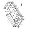
figure 1 is a general view in perspective of a hospital bed equipped with two patient mobility aid devices, one attached to the head frame and the other attached to the foot frame of the sleeping surface; -
figure 2 is an exploded view in perspective of such a patient mobility aid device; -
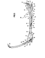
figure 3 is a transversal diagrammatic view illustrating the kinetics of the device, the grip being shown in the storage position on the right side and in the usage position on the left side; -
figures 4 to 8 are partial views in perspective showing the installation of a patient mobility aid device on the bed offigure 1 ; -
figure 9 is a detailed view in perspective showing a variation of the grip; -
figure 10 is a view from the perspective of the arrow X offigure 9 ; and -
figure 11 is a view from the perspective of the arrow XI offigure 10 . - With reference to the drawings, a hospital bed 11 is shown comprising an upper frame 13 forming a sleeping surface intended to receive a mattress, not shown. The upper frame comprises a
head frame 15 covered by apanel 16 and afoot frame 17 covered by a panel 18. The two frames are hinged on either side of a central part 20 (which itself includes two panels). The bed is also equipped with a headboard 22, afootboard 23 and twoside barriers 24, collapsible at the lower part of the upper frame 13. The twoframes central part 20. - The bed is equipped with at least one patient mobility aid device 25 (in this instance, two), enabling said patient to perform certain movements, particularly to sit up or lie down, or even to get in and out of bed if he is able to do so.
- In the illustrated embodiment, one of the
devices 25 is attached to thehead frame 15 and the other is attached to thefoot frame 17. - Each
device 25, seefigures 2 and3 , comprises a support crossmember 27 of a length corresponding to the width of the bed and at least one arm 29 (preferably two) ending in agrip 31. The crossmember is hollow in order to house the arm or each arm when the grip is in the stored position. In other words, eacharm 29 defines with the crossmember a telescopic structure such that thecorresponding grip 31 can be moved to a usage position situated above and outside the edge of the bed from its storage position near the respective end of the crossmember 27. - According to a preferred embodiment, the device is equipped with two
arms 29, each ending in agrip 31, projecting at one respective end of the crossmember. - More specifically, the crossmember 27 comprises a
rectilinear middle section 32 formed from a rail-type C-shaped metal structural shape, the open side facing the floor, and twoguide end fittings 34 disposed at the ends of saidmiddle section 32. Each guide end fitting is here composed of twoshells 35, symmetrical overall, made of plastic material, assembled by screws, to fit tightly around each end of said middle section and extend it. - The
end fittings 34 are mounted on the ends of themiddle section 32 and attached thereto. - The support crossmember 27 thus constructed is fitted at each of its ends with an attachment means shaped and sized to be attached to a side element of said bed. More specifically, the crossmember is mounted between two parallel
longitudinal elements 37 of thehead frame 15 or thefoot frame 17. Thus, the crossmember 27 can be mounted perpendicular to the longitudinal dimension of the bed between these two parallellongitudinal elements 37 of theframe - Each guide end fitting 34 comprises one such attachment means that is composed of a U-shaped bracket 40, opening laterally outward.
- The height of the bracket corresponds to the thickness of the
longitudinal element 37. At least one arm of the bracket, for example an arm 42 attached by screws to the lower part of the end fitting 34, is sufficiently flexible to allow a clamped fitting of the bracket 40 onto theelement 37 in spite of the presence on this arm 42 of aspur 44. Said spur is capable of cooperating with a corresponding hole 46 (figure 5 ) in thelongitudinal element 37, for attaching the assembly of said patient mobility aid device to the bed frame. - For example,
figures 4 to 8 illustrate the assembly and attachment of thedevice 25 to thefoot frame 17. Said assembly is begun by raising the panel 18, then the crossmember is fitted at an angle, the two brackets 40 being fitted between the elements 37 (figures 4 and 5 ). -
Figure 5 shows thehole 46 of one of theelements 37, at the lower part thereof. Then, as shown infigures 6 and 7 , thedevice 25 is pivoted in its entirety until thespur 44 of each bracket is inserted in the respective hole. Finally, the panel 18 is put back in place (figure 8 ), said panel having cutouts allowing the passage of the end portions of the guide end fittings on either side of the bed. It will be noted that when aside barrier 24 is raised, thearm 29 of the device situated on the same side cannot be raised. - As shown in the illustrated embodiment, each
arm 29 is curved, and the curved part, excluding thegrip 31, can be fully housed (figure 3 , right side) inside themiddle section 32 and the respective end fitting 34. - To accomplish this, each guide end fitting 34 comprises internally a guide channel 47, ascending overall, in which the arm is partially housed and slides. The channel 47 extends between an
aperture 49 of said end fitting 34 engaged at the corresponding end of saidmiddle section 32 and anupper outlet 51 defined above said attachment means, i.e. the bracket 40. - The relatively flexible plastic material of the end fitting makes it possible to stabilize the position of the
grip 31 by forced engagement with the end fitting. More precisely, said end fitting 34 comprises an elastic insertion indentation 48 of thegrip 31, defined in the vicinity of saidupper outlet 51 of the guide channel, for the immobilization of said grip in the storage position. - It should be noted that each guide channel 47 comprises a lower wall with a very wide V-shaped opening defining a concave bottom 52 in which, as will be discussed below, the lower end of the arm is supported and stabilized in the usage position (see
figure 3 , left part). - Each
arm 29 comprises a curved tubular section 54, one upper end 56 of which is flat for attaching thegrip 31. Said grip always projects out of theupper outlet 51 of the end fitting 34. - A
locking lever 58 is slidably engaged inside the other end of the tubular section. It comprises a round end 60 forming a sort of ball-and-socket joint and projecting from the tubular section 54. This round end 60 comprises two lateral extensions 62 engaging with indentations 64 defined along the inner walls of the guide channel 47. The tubular section 54 is also provided, in the vicinity of this end, with a transverse pin 65 that also engages with said indentations. These indentations are such that, when thearm 29 is pulled upward, the round end 60 of the lever penetrates into the end fitting 34 and reaches the above-mentioned concave bottom 52 of the guide channel. In the same path, each end of the pin 65 engages in a narrower upwardly extending extension 67 of the indentation 64. Said extensions, which have closed ends, constitute stops for the pin. - A coil spring 69 is installed in a
cavity 70 of thelever 58. It is inserted between the pin 65 and the bottom of said cavity, in order to push saidlever 58 towards the interior of the curved tubular section 54, as can be seen infigure 3 , right portion. Furthermore, the inner end of the lever, engaged in the tubular section, is provided with alateral push button 74. The tubular section is provided with ahole 76 located in the vicinity of the push button (to the left of the push button in the right portion offigure 3 ) and aleaf spring 79 is attached to the push button and is in sliding contact with the inner wall of the curved tubular section 54. Thus, saidpush button 74 is pushed to engage in thehole 76 when it reaches a position facing said hole through relative movement between the lever and the curved section. - When it is desired to use the patient mobility aid device, the
grip 31 is pulled upward and outward. At first, the arm assembly slides in the guide cavity, pulling the lockinglever 58 with it. Toward the end of the path, the rounded end 60 is guided by the indentations 64 and the arm stands up. At the end of the path, the ends of the pin 65 engage in the extensions 67 of the indentations, which results in the compression of the spring 69 and thus a relative movement between the curved tubular section 54 and thelever 58. This movement causes engagement of thepush button 74 in thehole 76. At this point, the situation is as represented infigure 3 , left side, where the slightly extended arm, now of a fixed length, is held in the standing position by a wedging effect between the concave bottom 52 and theupper outlet 51. To replace the arm and its grip in the storage position, thepush button 79 is pushed to cause it to enter the curved tubular section 54 while pushing down on thegrip 31. - It should be noted that, because each patient mobility aid device is mounted on a pivoting
frame - According to one variation, represented in
figures 9 to 11 , thegrip 131 comprises, at one side of its point of attachment to saidarm 29, acurved handle 132 extending beyond said point of attachment, to facilitate gripping in the sit-up phase of the patient. The handle here is curved downward. Moreover, said grip is extended on the other side of the point of attachment to thearm 29 by ahelical segment 134 of oblong cross section facilitating thrust in the final phase of the patient's sitting upright, while opposing the grip reflex. These two features are independent, in particular the helical segment can constitute the grip with or without a handle, which, if there is one, can have a different shape.
Claims (10)
- Hospital bed having a patient mobility aid device, wherein said device comprises a support crossmember (27) of a length corresponding to the width of said bed and provided at each of its ends with an attachment means (40) shaped and sized to be attached to a side element (37) of said bed, wherein said crossmember is hollow and houses at least one arm (29) terminating in a grip (31), and wherein said arm defines with the crossmember a telescopic structure such that said grip can be moved to a usable position situated above and to the side of the edge of the bed from a storage position in the vicinity of an end of said crossmember.
- Hospital bed as claimed in claim 1, wherein said mobility aid device comprises two arms (29), each with a grip (31) at the end, projecting from each end of said support crossmember (27).
- Hospital bed as claimed in claim 1 or 2, wherein said crossmember comprises a middle section (32) and two guide end fittings (34) respectively disposed at the ends of said middle section and in that the attachment means is formed of a U-shaped bracket (40) provided in each guide end fitting, opening laterally outward, the height of said bracket corresponding to the thickness of a longitudinal element of a frame of said bed, so that said crossmember is mounted between two such longitudinal elements parallel to said frame.
- Hospital bed as claimed in claim 3, wherein at least one arm (42) of said bracket is flexible and includes a spur (44) cooperating with a corresponding hole in said longitudinal element, for attaching the assembly of said mobility aid device to said bed frame.
- Hospital bed as claimed in either claim 3 or claim 4, wherein the or each arm (29) is curved and in that each guide end fitting (34) comprises a guide channel (47) in which the arm slides, said channel (47) extending between an aperture (49) of said end fitting (34) which engages the corresponding end of said middle section (32) and an upper outlet (51) defined above said attachment means (40).
- Hospital bed according to claim 5, wherein said curved arm has a curved tubular section (54) one end of which carries the grip which projects out of said upper outlet (51) of the end fitting, and in that a locking lever (58) is slidably engaged inside the other end of said tubular section, in that said lever has a round end (60) projecting from said tubular section and is provided with lateral extensions engaging with indentations defined along the inner walls of said guide channel, in that said tubular section is equipped, in the vicinity of said other end, with a transversal pin (65) that engages with said indentations, in that a spring (69) is installed in a cavity of said lever and is inserted between said pin and the bottom of said cavity, in order to bias said lever towards the interior of said curved tubular section, in that the inner end of said lever is provided with a lateral push button (74) for forming a lock, in that said tubular section is provided with a hole (76) located in the vicinity of the push button and in that a spring (79) is attached to said push button and is in sliding contact with the inner wall of said curved tubular section in order to push said push button into engagement in said hole when said lock-forming push button reaches a position facing said hole.
- Hospital bed as claimed in either claim 5 or 6, wherein said end fitting (34) has an indentation (48), defined in the vicinity of said upper outlet (51) of the guide channel for fixing the grip in the storage position.
- Hospital bed according to any preceding claim wherein it comprises a sleeping surface in several parts hinged to one another, in particular a head frame (15) and/or a foot frame (17) adjustable with respect to a central portion and wherein the mobility aid device is installed on said head frame and/or on said foot frame.
- Hospital bed according to any preceding claim wherein said grip includes a helical segment of oblong cross section (134).
- Hospital bed according to any preceding claim wherein said grip includes a curved handle (132).
Applications Claiming Priority (2)
| Application Number | Priority Date | Filing Date | Title |
|---|---|---|---|
| US22648609P | 2009-07-17 | 2009-07-17 | |
| FR1050299A FR2955251B1 (en) | 2010-01-18 | 2010-01-18 | MEDICALIZED BED EQUIPPED WITH A DEVICE FOR AIDING THE MOBILITY OF A PATIENT. |
Publications (3)
| Publication Number | Publication Date |
|---|---|
| EP2275072A2 true EP2275072A2 (en) | 2011-01-19 |
| EP2275072A3 EP2275072A3 (en) | 2011-03-09 |
| EP2275072B1 EP2275072B1 (en) | 2012-11-07 |
Family
ID=42663680
Family Applications (1)
| Application Number | Title | Priority Date | Filing Date |
|---|---|---|---|
| EP10251243A Not-in-force EP2275072B1 (en) | 2009-07-17 | 2010-07-12 | Hospital bed with patient mobility aid device |
Country Status (4)
| Country | Link |
|---|---|
| US (1) | US8370978B2 (en) |
| EP (1) | EP2275072B1 (en) |
| JP (1) | JP2011019919A (en) |
| FR (1) | FR2955251B1 (en) |
Families Citing this family (3)
| Publication number | Priority date | Publication date | Assignee | Title |
|---|---|---|---|---|
| US11206996B2 (en) * | 2015-10-14 | 2021-12-28 | Qfix Systems, Llc | Patient trolley and patient transfer device |
| US11737934B2 (en) | 2015-10-14 | 2023-08-29 | Qfix Systems, Llc | MRI compatible patient trolley |
| US20210298972A1 (en) | 2018-12-19 | 2021-09-30 | Ligia Beatriz Rodriguez-Aguilar | Retractable bed for subjects with limited or no mobility |
Family Cites Families (49)
| Publication number | Priority date | Publication date | Assignee | Title |
|---|---|---|---|---|
| US2585660A (en) | 1949-01-31 | 1952-02-12 | Otto B Kjos | Patient's bedease |
| US3312986A (en) | 1964-04-25 | 1967-04-11 | Brock M Fahrni | Bedside support |
| US3905591A (en) * | 1970-09-24 | 1975-09-16 | Siemens Ag | Patient{3 s couch |
| EP0007708B1 (en) | 1978-07-05 | 1981-11-04 | Alfred Walter Barker | Mobility aid |
| US4277100A (en) | 1979-10-18 | 1981-07-07 | Gael Beougher | Ambulatory apparatus |
| EP0058643A1 (en) | 1981-02-16 | 1982-08-25 | VALHAUS TRUST Reg | Support for bed |
| US4941708A (en) | 1988-09-27 | 1990-07-17 | Heffner H Hugh | Lifting apparatus |
| US4932090A (en) | 1989-04-12 | 1990-06-12 | Johansson Paul J | Movable support bar |
| US5038430A (en) * | 1990-03-22 | 1991-08-13 | Invacare Corporation | Attaching means for bed cross brace |
| US6374436B1 (en) | 1994-01-25 | 2002-04-23 | Hill-Rom Services, Inc. | Hospital bed |
| US5680661A (en) | 1990-05-16 | 1997-10-28 | Hill-Rom, Inc. | Hospital bed with user care apparatus |
| US5060327A (en) * | 1990-10-18 | 1991-10-29 | Hill-Rom Company, Inc. | Labor grips for birthing bed |
| USD336578S (en) | 1990-12-14 | 1993-06-22 | Hill-Rom Company, Inc. | Hand grip for a birthing bed |
| US5195200A (en) | 1992-04-17 | 1993-03-23 | Thomas Leoutsakos | Manual support apparatus attachable to a bedframe |
| US5257426A (en) | 1992-04-17 | 1993-11-02 | Thomas Leoutsakos | Manual support apparatus attachable to a bedframe |
| US5231721A (en) | 1992-08-03 | 1993-08-03 | Michael Fish | Removable bedside grab bar (post) |
| US5384927A (en) | 1993-01-27 | 1995-01-31 | Canadian Aging & Rehabilitation Product Development Corp. | Security rail attachment for a bed |
| US5337430A (en) | 1993-04-28 | 1994-08-16 | Schlein Allen P | Device for assisting a person to transfer into and from a bed |
| US5335385A (en) | 1993-05-10 | 1994-08-09 | Brown David J | Support mechanism for a bed |
| JPH0718699U (en) * | 1993-09-16 | 1995-04-04 | 大成建設株式会社 | Toilet bowl for the elderly and disabled |
| US5394581A (en) | 1993-10-07 | 1995-03-07 | Leoutsakos; Thomas | Manual support apparatus |
| US5586352A (en) | 1994-05-02 | 1996-12-24 | O'brien; John L. | Support pole with a pivoting and locking handrail for elderly and disabled persons |
| JP2595474B2 (en) * | 1994-11-17 | 1997-04-02 | パラマウントベッド株式会社 | Bed with floor-mounted side fence |
| US5737783A (en) | 1995-02-13 | 1998-04-14 | Antinori; Santino | Mattress retention bracket for adjustable beds |
| US5678267A (en) | 1995-07-11 | 1997-10-21 | Kinder; Florence E. | Medical examination table handle system |
| JP2845319B2 (en) * | 1996-09-27 | 1999-01-13 | パラマウントベッド株式会社 | Floor-following side fence in bed |
| US6240583B1 (en) | 1996-12-03 | 2001-06-05 | Hill-Rom, Inc. | Ambulatory assist arm for a bed |
| US6058531A (en) | 1997-05-23 | 2000-05-09 | Carroll Intelli Corp. | Dual-position assist and guard rail for beds |
| US5839136A (en) | 1997-05-23 | 1998-11-24 | Ferno-Washington, Inc. | Cot mountable arm rest and cot incorporating same |
| DE29709508U1 (en) * | 1997-05-31 | 1997-08-28 | Vauth-Sagel GmbH & Co, 33034 Brakel | Mobility aid for / on a care bed |
| DE19825344A1 (en) | 1998-06-06 | 1999-12-09 | Koszlat Heinz | Rising aid and gripping handle arrangement enables esp. the elderly and handicapped to rise from e.g. a lying position in e.g. a bath or bed, without having to let go of the handle |
| US6138301A (en) | 1999-03-22 | 2000-10-31 | Tubular Fabricators Industry | Bed transfer device |
| US6209155B1 (en) * | 1999-03-26 | 2001-04-03 | Fredman Bros. Furniture Company, Inc. | Fastener for adjustable cross bar for bed rails and frames |
| US6134731A (en) | 1999-04-01 | 2000-10-24 | Bel-Art Products, Inc. | Adjustable support apparatus |
| CA2311187A1 (en) | 1999-08-12 | 2001-02-12 | Hill-Rom, Inc. | Ambulatory assist arm for a bed |
| US6167895B1 (en) | 1999-10-08 | 2001-01-02 | Gary W. Burroughs | Adjustable mobility assistance device |
| USD459119S1 (en) | 2001-04-05 | 2002-06-25 | Hill-Rom Services, Inc. | Siderail support arm |
| USD458481S1 (en) | 2001-04-05 | 2002-06-11 | Hill-Rom Services, Inc. | Slats of a bed siderail |
| US6728985B2 (en) | 2001-08-15 | 2004-05-04 | Hill-Rom Services, Inc. | Ambulatory assist arm apparatus |
| EP1487392B1 (en) | 2002-03-05 | 2008-05-14 | Hill-Rom Services, Inc. | Handle for hospital bed |
| JP4212886B2 (en) * | 2002-12-24 | 2009-01-21 | 有限会社キャピタル | wheelchair |
| US7150058B2 (en) | 2003-02-28 | 2006-12-19 | Sunrise Medical Hhg Inc. | Assist handle assembly for beds |
| USD520783S1 (en) | 2004-10-01 | 2006-05-16 | M.C. Healthcare Products Inc. | Rotating assist rail |
| CZ15082U1 (en) * | 2004-11-30 | 2005-01-31 | Linet S. R. O. | Grab handle controlled by patient without aid of medical personnel and a bed provided with such a grab rail |
| CA2505083A1 (en) * | 2005-03-07 | 2006-09-07 | Hill-Rom Services, Inc. | Siderails for a hospital bed |
| USD535544S1 (en) | 2005-07-28 | 2007-01-23 | The Brewer Company, Llc | Grab bar |
| US7797775B2 (en) | 2007-10-02 | 2010-09-21 | Stander, Inc. | Sliding mobility assistance device |
| US8239986B2 (en) * | 2008-03-13 | 2012-08-14 | Hill-Rom Services, Inc. | Siderail assembly for a patient-support apparatus |
| US7805789B1 (en) | 2009-02-27 | 2010-10-05 | Mark Ronald Dean | Assist handle for a bed |
-
2010
- 2010-01-18 FR FR1050299A patent/FR2955251B1/en not_active Expired - Fee Related
- 2010-07-12 EP EP10251243A patent/EP2275072B1/en not_active Not-in-force
- 2010-07-13 US US12/834,955 patent/US8370978B2/en not_active Expired - Fee Related
- 2010-07-20 JP JP2010163009A patent/JP2011019919A/en active Pending
Non-Patent Citations (1)
| Title |
|---|
| None |
Also Published As
| Publication number | Publication date |
|---|---|
| FR2955251A1 (en) | 2011-07-22 |
| EP2275072B1 (en) | 2012-11-07 |
| US20110010864A1 (en) | 2011-01-20 |
| US8370978B2 (en) | 2013-02-12 |
| FR2955251B1 (en) | 2013-06-28 |
| JP2011019919A (en) | 2011-02-03 |
| EP2275072A3 (en) | 2011-03-09 |
Similar Documents
| Publication | Publication Date | Title |
|---|---|---|
| US7487558B2 (en) | Headboard for a pull-up-in-bed system | |
| US9314106B2 (en) | Bed step device and method | |
| US7412735B2 (en) | Patient support apparatus | |
| US8578531B2 (en) | Assist handle assemblies and beds with an assist handle assembly | |
| US6728985B2 (en) | Ambulatory assist arm apparatus | |
| US8235407B2 (en) | Wheelchair with adjustable seat | |
| US9009888B1 (en) | Health care bed with variably sized bed frame and method of use thereof | |
| US8474921B2 (en) | Wall-mounted patient egress and patient assist bar | |
| CA2902544C (en) | Siderail system for a bed | |
| US20060101578A1 (en) | Side rail assembly for beds | |
| EP2275072B1 (en) | Hospital bed with patient mobility aid device | |
| WO2013082577A1 (en) | Walking safety aid apparatus | |
| JP2011067448A (en) | Bathroom chair | |
| EP3075367B1 (en) | Health care bed with variable width bed frame | |
| US20190059601A1 (en) | Adjustable support legs for a mattress foundation | |
| EP2668873B1 (en) | Locking for a bed safety rail | |
| JP2014176752A (en) | Bathroom chair | |
| KR200461319Y1 (en) | A lateral frame of a medical bed | |
| JP2017042503A (en) | Hand rail for toilet bowl | |
| CN107809991B (en) | Medical and/or nursing beds and side rails therefor | |
| US20120186375A1 (en) | Manual Height Adjustable Assembly For A Crib | |
| JP3716013B2 (en) | Study desk chair | |
| JP2013215598A (en) | Portable toilet | |
| KR200466002Y1 (en) | Movable toilet to be Folded for old man | |
| JP4203794B2 (en) | Self-closing door holding device and door handle with stopper function |
Legal Events
| Date | Code | Title | Description |
|---|---|---|---|
| PUAI | Public reference made under article 153(3) epc to a published international application that has entered the european phase |
Free format text: ORIGINAL CODE: 0009012 |
|
| AK | Designated contracting states |
Kind code of ref document: A2 Designated state(s): AL AT BE BG CH CY CZ DE DK EE ES FI FR GB GR HR HU IE IS IT LI LT LU LV MC MK MT NL NO PL PT RO SE SI SK SM TR |
|
| AX | Request for extension of the european patent |
Extension state: BA ME RS |
|
| PUAL | Search report despatched |
Free format text: ORIGINAL CODE: 0009013 |
|
| AK | Designated contracting states |
Kind code of ref document: A3 Designated state(s): AL AT BE BG CH CY CZ DE DK EE ES FI FR GB GR HR HU IE IS IT LI LT LU LV MC MK MT NL NO PL PT RO SE SI SK SM TR |
|
| AX | Request for extension of the european patent |
Extension state: BA ME RS |
|
| 17P | Request for examination filed |
Effective date: 20110907 |
|
| 17Q | First examination report despatched |
Effective date: 20111201 |
|
| GRAP | Despatch of communication of intention to grant a patent |
Free format text: ORIGINAL CODE: EPIDOSNIGR1 |
|
| GRAS | Grant fee paid |
Free format text: ORIGINAL CODE: EPIDOSNIGR3 |
|
| GRAA | (expected) grant |
Free format text: ORIGINAL CODE: 0009210 |
|
| AK | Designated contracting states |
Kind code of ref document: B1 Designated state(s): AL AT BE BG CH CY CZ DE DK EE ES FI FR GB GR HR HU IE IS IT LI LT LU LV MC MK MT NL NO PL PT RO SE SI SK SM TR |
|
| REG | Reference to a national code |
Ref country code: GB Ref legal event code: FG4D |
|
| REG | Reference to a national code |
Ref country code: AT Ref legal event code: REF Ref document number: 582681 Country of ref document: AT Kind code of ref document: T Effective date: 20121115 Ref country code: CH Ref legal event code: EP |
|
| REG | Reference to a national code |
Ref country code: IE Ref legal event code: FG4D |
|
| REG | Reference to a national code |
Ref country code: DE Ref legal event code: R096 Ref document number: 602010003504 Country of ref document: DE Effective date: 20130103 |
|
| REG | Reference to a national code |
Ref country code: AT Ref legal event code: MK05 Ref document number: 582681 Country of ref document: AT Kind code of ref document: T Effective date: 20121107 |
|
| REG | Reference to a national code |
Ref country code: NL Ref legal event code: VDEP Effective date: 20121107 |
|
| REG | Reference to a national code |
Ref country code: LT Ref legal event code: MG4D |
|
| PG25 | Lapsed in a contracting state [announced via postgrant information from national office to epo] |
Ref country code: SE Free format text: LAPSE BECAUSE OF FAILURE TO SUBMIT A TRANSLATION OF THE DESCRIPTION OR TO PAY THE FEE WITHIN THE PRESCRIBED TIME-LIMIT Effective date: 20121107 Ref country code: HR Free format text: LAPSE BECAUSE OF FAILURE TO SUBMIT A TRANSLATION OF THE DESCRIPTION OR TO PAY THE FEE WITHIN THE PRESCRIBED TIME-LIMIT Effective date: 20121107 Ref country code: IS Free format text: LAPSE BECAUSE OF FAILURE TO SUBMIT A TRANSLATION OF THE DESCRIPTION OR TO PAY THE FEE WITHIN THE PRESCRIBED TIME-LIMIT Effective date: 20130307 Ref country code: NO Free format text: LAPSE BECAUSE OF FAILURE TO SUBMIT A TRANSLATION OF THE DESCRIPTION OR TO PAY THE FEE WITHIN THE PRESCRIBED TIME-LIMIT Effective date: 20130207 Ref country code: FI Free format text: LAPSE BECAUSE OF FAILURE TO SUBMIT A TRANSLATION OF THE DESCRIPTION OR TO PAY THE FEE WITHIN THE PRESCRIBED TIME-LIMIT Effective date: 20121107 Ref country code: NL Free format text: LAPSE BECAUSE OF FAILURE TO SUBMIT A TRANSLATION OF THE DESCRIPTION OR TO PAY THE FEE WITHIN THE PRESCRIBED TIME-LIMIT Effective date: 20121107 Ref country code: LT Free format text: LAPSE BECAUSE OF FAILURE TO SUBMIT A TRANSLATION OF THE DESCRIPTION OR TO PAY THE FEE WITHIN THE PRESCRIBED TIME-LIMIT Effective date: 20121107 |
|
| PG25 | Lapsed in a contracting state [announced via postgrant information from national office to epo] |
Ref country code: LV Free format text: LAPSE BECAUSE OF FAILURE TO SUBMIT A TRANSLATION OF THE DESCRIPTION OR TO PAY THE FEE WITHIN THE PRESCRIBED TIME-LIMIT Effective date: 20121107 Ref country code: GR Free format text: LAPSE BECAUSE OF FAILURE TO SUBMIT A TRANSLATION OF THE DESCRIPTION OR TO PAY THE FEE WITHIN THE PRESCRIBED TIME-LIMIT Effective date: 20130208 Ref country code: PT Free format text: LAPSE BECAUSE OF FAILURE TO SUBMIT A TRANSLATION OF THE DESCRIPTION OR TO PAY THE FEE WITHIN THE PRESCRIBED TIME-LIMIT Effective date: 20130307 Ref country code: BE Free format text: LAPSE BECAUSE OF FAILURE TO SUBMIT A TRANSLATION OF THE DESCRIPTION OR TO PAY THE FEE WITHIN THE PRESCRIBED TIME-LIMIT Effective date: 20121107 Ref country code: PL Free format text: LAPSE BECAUSE OF FAILURE TO SUBMIT A TRANSLATION OF THE DESCRIPTION OR TO PAY THE FEE WITHIN THE PRESCRIBED TIME-LIMIT Effective date: 20121107 Ref country code: SI Free format text: LAPSE BECAUSE OF FAILURE TO SUBMIT A TRANSLATION OF THE DESCRIPTION OR TO PAY THE FEE WITHIN THE PRESCRIBED TIME-LIMIT Effective date: 20121107 |
|
| PG25 | Lapsed in a contracting state [announced via postgrant information from national office to epo] |
Ref country code: AT Free format text: LAPSE BECAUSE OF FAILURE TO SUBMIT A TRANSLATION OF THE DESCRIPTION OR TO PAY THE FEE WITHIN THE PRESCRIBED TIME-LIMIT Effective date: 20121107 |
|
| PG25 | Lapsed in a contracting state [announced via postgrant information from national office to epo] |
Ref country code: DK Free format text: LAPSE BECAUSE OF FAILURE TO SUBMIT A TRANSLATION OF THE DESCRIPTION OR TO PAY THE FEE WITHIN THE PRESCRIBED TIME-LIMIT Effective date: 20121107 Ref country code: CZ Free format text: LAPSE BECAUSE OF FAILURE TO SUBMIT A TRANSLATION OF THE DESCRIPTION OR TO PAY THE FEE WITHIN THE PRESCRIBED TIME-LIMIT Effective date: 20121107 Ref country code: EE Free format text: LAPSE BECAUSE OF FAILURE TO SUBMIT A TRANSLATION OF THE DESCRIPTION OR TO PAY THE FEE WITHIN THE PRESCRIBED TIME-LIMIT Effective date: 20121107 Ref country code: SK Free format text: LAPSE BECAUSE OF FAILURE TO SUBMIT A TRANSLATION OF THE DESCRIPTION OR TO PAY THE FEE WITHIN THE PRESCRIBED TIME-LIMIT Effective date: 20121107 Ref country code: BG Free format text: LAPSE BECAUSE OF FAILURE TO SUBMIT A TRANSLATION OF THE DESCRIPTION OR TO PAY THE FEE WITHIN THE PRESCRIBED TIME-LIMIT Effective date: 20130207 |
|
| PG25 | Lapsed in a contracting state [announced via postgrant information from national office to epo] |
Ref country code: RO Free format text: LAPSE BECAUSE OF FAILURE TO SUBMIT A TRANSLATION OF THE DESCRIPTION OR TO PAY THE FEE WITHIN THE PRESCRIBED TIME-LIMIT Effective date: 20121107 Ref country code: IT Free format text: LAPSE BECAUSE OF FAILURE TO SUBMIT A TRANSLATION OF THE DESCRIPTION OR TO PAY THE FEE WITHIN THE PRESCRIBED TIME-LIMIT Effective date: 20121107 |
|
| PLBE | No opposition filed within time limit |
Free format text: ORIGINAL CODE: 0009261 |
|
| STAA | Information on the status of an ep patent application or granted ep patent |
Free format text: STATUS: NO OPPOSITION FILED WITHIN TIME LIMIT |
|
| 26N | No opposition filed |
Effective date: 20130808 |
|
| PG25 | Lapsed in a contracting state [announced via postgrant information from national office to epo] |
Ref country code: ES Free format text: LAPSE BECAUSE OF FAILURE TO SUBMIT A TRANSLATION OF THE DESCRIPTION OR TO PAY THE FEE WITHIN THE PRESCRIBED TIME-LIMIT Effective date: 20130218 |
|
| PG25 | Lapsed in a contracting state [announced via postgrant information from national office to epo] |
Ref country code: CY Free format text: LAPSE BECAUSE OF FAILURE TO SUBMIT A TRANSLATION OF THE DESCRIPTION OR TO PAY THE FEE WITHIN THE PRESCRIBED TIME-LIMIT Effective date: 20121107 |
|
| REG | Reference to a national code |
Ref country code: DE Ref legal event code: R097 Ref document number: 602010003504 Country of ref document: DE Effective date: 20130808 |
|
| PG25 | Lapsed in a contracting state [announced via postgrant information from national office to epo] |
Ref country code: MC Free format text: LAPSE BECAUSE OF FAILURE TO SUBMIT A TRANSLATION OF THE DESCRIPTION OR TO PAY THE FEE WITHIN THE PRESCRIBED TIME-LIMIT Effective date: 20121107 |
|
| REG | Reference to a national code |
Ref country code: IE Ref legal event code: MM4A |
|
| PG25 | Lapsed in a contracting state [announced via postgrant information from national office to epo] |
Ref country code: IE Free format text: LAPSE BECAUSE OF NON-PAYMENT OF DUE FEES Effective date: 20130712 |
|
| REG | Reference to a national code |
Ref country code: CH Ref legal event code: PL |
|
| PG25 | Lapsed in a contracting state [announced via postgrant information from national office to epo] |
Ref country code: LI Free format text: LAPSE BECAUSE OF NON-PAYMENT OF DUE FEES Effective date: 20140731 Ref country code: CH Free format text: LAPSE BECAUSE OF NON-PAYMENT OF DUE FEES Effective date: 20140731 |
|
| PG25 | Lapsed in a contracting state [announced via postgrant information from national office to epo] |
Ref country code: SM Free format text: LAPSE BECAUSE OF FAILURE TO SUBMIT A TRANSLATION OF THE DESCRIPTION OR TO PAY THE FEE WITHIN THE PRESCRIBED TIME-LIMIT Effective date: 20121107 |
|
| PG25 | Lapsed in a contracting state [announced via postgrant information from national office to epo] |
Ref country code: MT Free format text: LAPSE BECAUSE OF FAILURE TO SUBMIT A TRANSLATION OF THE DESCRIPTION OR TO PAY THE FEE WITHIN THE PRESCRIBED TIME-LIMIT Effective date: 20121107 Ref country code: TR Free format text: LAPSE BECAUSE OF FAILURE TO SUBMIT A TRANSLATION OF THE DESCRIPTION OR TO PAY THE FEE WITHIN THE PRESCRIBED TIME-LIMIT Effective date: 20121107 |
|
| PG25 | Lapsed in a contracting state [announced via postgrant information from national office to epo] |
Ref country code: MK Free format text: LAPSE BECAUSE OF FAILURE TO SUBMIT A TRANSLATION OF THE DESCRIPTION OR TO PAY THE FEE WITHIN THE PRESCRIBED TIME-LIMIT Effective date: 20121107 Ref country code: LU Free format text: LAPSE BECAUSE OF NON-PAYMENT OF DUE FEES Effective date: 20130712 Ref country code: HU Free format text: LAPSE BECAUSE OF FAILURE TO SUBMIT A TRANSLATION OF THE DESCRIPTION OR TO PAY THE FEE WITHIN THE PRESCRIBED TIME-LIMIT; INVALID AB INITIO Effective date: 20100712 |
|
| REG | Reference to a national code |
Ref country code: FR Ref legal event code: PLFP Year of fee payment: 7 |
|
| REG | Reference to a national code |
Ref country code: FR Ref legal event code: PLFP Year of fee payment: 8 |
|
| PGFP | Annual fee paid to national office [announced via postgrant information from national office to epo] |
Ref country code: GB Payment date: 20170620 Year of fee payment: 8 Ref country code: FR Payment date: 20170621 Year of fee payment: 8 |
|
| PGFP | Annual fee paid to national office [announced via postgrant information from national office to epo] |
Ref country code: DE Payment date: 20170620 Year of fee payment: 8 |
|
| PG25 | Lapsed in a contracting state [announced via postgrant information from national office to epo] |
Ref country code: AL Free format text: LAPSE BECAUSE OF FAILURE TO SUBMIT A TRANSLATION OF THE DESCRIPTION OR TO PAY THE FEE WITHIN THE PRESCRIBED TIME-LIMIT Effective date: 20121107 |
|
| REG | Reference to a national code |
Ref country code: DE Ref legal event code: R119 Ref document number: 602010003504 Country of ref document: DE |
|
| GBPC | Gb: european patent ceased through non-payment of renewal fee |
Effective date: 20180712 |
|
| PG25 | Lapsed in a contracting state [announced via postgrant information from national office to epo] |
Ref country code: FR Free format text: LAPSE BECAUSE OF NON-PAYMENT OF DUE FEES Effective date: 20180731 Ref country code: GB Free format text: LAPSE BECAUSE OF NON-PAYMENT OF DUE FEES Effective date: 20180712 Ref country code: DE Free format text: LAPSE BECAUSE OF NON-PAYMENT OF DUE FEES Effective date: 20190201 |