EP2275015A1 - Stacked sheet body and sheet storing device - Google Patents
Stacked sheet body and sheet storing device Download PDFInfo
- Publication number
- EP2275015A1 EP2275015A1 EP09728963A EP09728963A EP2275015A1 EP 2275015 A1 EP2275015 A1 EP 2275015A1 EP 09728963 A EP09728963 A EP 09728963A EP 09728963 A EP09728963 A EP 09728963A EP 2275015 A1 EP2275015 A1 EP 2275015A1
- Authority
- EP
- European Patent Office
- Prior art keywords
- piece
- sheet
- sheet body
- sheets
- bodies
- Prior art date
- Legal status (The legal status is an assumption and is not a legal conclusion. Google has not performed a legal analysis and makes no representation as to the accuracy of the status listed.)
- Granted
Links
Images



Classifications
-
- B—PERFORMING OPERATIONS; TRANSPORTING
- B65—CONVEYING; PACKING; STORING; HANDLING THIN OR FILAMENTARY MATERIAL
- B65D—CONTAINERS FOR STORAGE OR TRANSPORT OF ARTICLES OR MATERIALS, e.g. BAGS, BARRELS, BOTTLES, BOXES, CANS, CARTONS, CRATES, DRUMS, JARS, TANKS, HOPPERS, FORWARDING CONTAINERS; ACCESSORIES, CLOSURES, OR FITTINGS THEREFOR; PACKAGING ELEMENTS; PACKAGES
- B65D83/00—Containers or packages with special means for dispensing contents
- B65D83/08—Containers or packages with special means for dispensing contents for dispensing thin flat articles in succession
- B65D83/0894—Containers or packages with special means for dispensing contents for dispensing thin flat articles in succession the articles being positioned relative to one another or to the container in a special way, e.g. for facilitating dispensing, without additional support
-
- A—HUMAN NECESSITIES
- A47—FURNITURE; DOMESTIC ARTICLES OR APPLIANCES; COFFEE MILLS; SPICE MILLS; SUCTION CLEANERS IN GENERAL
- A47K—SANITARY EQUIPMENT; ACCESSORIES THEREFOR, e.g. TOILET ACCESSORIES
- A47K10/00—Body-drying implements; Toilet paper; Holders therefor
- A47K10/24—Towel dispensers; Toilet paper dispensers
- A47K10/32—Dispensers for paper towels or toilet paper
- A47K10/42—Dispensers for paper towels or toilet paper dispensing from a store of single sheets, e.g. stacked
- A47K2010/428—Details of the folds or interfolds of the sheets
-
- Y—GENERAL TAGGING OF NEW TECHNOLOGICAL DEVELOPMENTS; GENERAL TAGGING OF CROSS-SECTIONAL TECHNOLOGIES SPANNING OVER SEVERAL SECTIONS OF THE IPC; TECHNICAL SUBJECTS COVERED BY FORMER USPC CROSS-REFERENCE ART COLLECTIONS [XRACs] AND DIGESTS
- Y10—TECHNICAL SUBJECTS COVERED BY FORMER USPC
- Y10T—TECHNICAL SUBJECTS COVERED BY FORMER US CLASSIFICATION
- Y10T428/00—Stock material or miscellaneous articles
- Y10T428/24—Structurally defined web or sheet [e.g., overall dimension, etc.]
- Y10T428/2419—Fold at edge
- Y10T428/24215—Acute or reverse fold of exterior component
- Y10T428/24231—At opposed marginal edges
-
- Y—GENERAL TAGGING OF NEW TECHNOLOGICAL DEVELOPMENTS; GENERAL TAGGING OF CROSS-SECTIONAL TECHNOLOGIES SPANNING OVER SEVERAL SECTIONS OF THE IPC; TECHNICAL SUBJECTS COVERED BY FORMER USPC CROSS-REFERENCE ART COLLECTIONS [XRACs] AND DIGESTS
- Y10—TECHNICAL SUBJECTS COVERED BY FORMER USPC
- Y10T—TECHNICAL SUBJECTS COVERED BY FORMER US CLASSIFICATION
- Y10T428/00—Stock material or miscellaneous articles
- Y10T428/24—Structurally defined web or sheet [e.g., overall dimension, etc.]
- Y10T428/2419—Fold at edge
- Y10T428/24264—Particular fold structure [e.g., beveled, etc.]
Definitions
- the invention relates to a technique of forming a stack of sheets by stacking a plurality of sheets one on another.
- Japanese non-examined laid-open Patent Publication No. H06-23774 discloses a sheet container including a stack of sheets formed by folding wet tissues and a sheet container for containing the stack of sheets.
- sheets are stacked one on another while partly overlapping one another (being partly wrapped one around another).
- a sheet to be taken out next
- Friction between sheets depends on the material of the sheets and the contact area between the sheets. Wet tissues are used in the impregnated state (wet state) with impregnating liquid, so that high friction is caused between the sheets.
- an object of the invention to provide a technique for reducing the contact area between adjacent sheets to be stacked one on another without increasing the width of a stack of sheets.
- One aspect of the invention relates to a stack of sheets which is formed by stacking sheet bodies one on another, each of which is formed by folding a sheet and has a plurality of pieces.
- the sheet body is typically formed by folding a rectangular or square sheet.
- This invention particularly relates to a stack of sheets in which the sheet bodies are stacked one on another in such a manner that one of the pieces of each sheet body on one side in a stacking direction and another piece on the other side are inserted between pieces of an adjacent sheet body on one side in the stacking direction with respect to the sheet body and between pieces of an adjacent sheet body on the other side in the stacking direction, respectively.
- auxiliary piece is formed by folding an end of the piece of the sheet bodies which lies on one of the opposite sides in the stacking direction. The position and shape of the auxiliary piece can be appropriately selected such that the area of an overlapping region between adjacent sheets can be reduced by provision of the auxiliary piece.
- the overlapping width of the overlapping region between adjacent sheet bodies can be adjusted by adjusting the length of the auxiliary piece. In this manner, friction between adjacent sheet bodies can be reduced to an appropriate value, so that the sheet bodies can be taken out with stability.
- the technique of the invention is effective in stacking sheets having a width more than twice as large as the width of the stack of sheets.
- Another aspect of this invention relates to a stack of sheets which is formed by stacking first and second sheet bodies one on another, each of which is formed by folding a sheet.
- the sheets are typically rectangular or square.
- Each of the first sheet bodies has a first piece, a second piece and a third piece between both ends of the sheet body, and the first piece and the third piece are folded in opposite directions to each other with respect to the second piece.
- the first sheet body typically comprises a Z-shaped sheet body as viewed from the direction of the width (the direction perpendicular to the folding lines).
- each of the second sheet bodies has a fourth piece and a fifth piece between both ends of the sheet body.
- the second sheet body typically comprises a V-shaped sheet body as viewed from the direction of the width (the direction perpendicular to the folding lines).
- the first sheet bodies and the second sheet bodies are alternately stacked one on another in such a manner that the fourth piece and the fifth piece of each of the second sheet bodies are inserted between the second piece and the third piece of a first sheet body adjacent to the second sheet body on one side in a stacking direction and between the first piece and the second piece of a first sheet body adjacent to the second sheet body on the other side in the stacking direction, respectively.
- the first sheet bodies and the second sheet bodies are stacked one on another in various manners in which the first and second sheet bodies can be continuously taken out one by one from an end of one side (the take-out opening side) of the stack of sheets.
- an auxiliary piece is formed by folding an end of the piece of each of the first and second sheet bodies which lies on one of the opposite sides in the stacking direction.
- the position and shape of the auxiliary piece can be appropriately selected such that an overlapping region between adjacent sheet bodies can be reduced by provision of the auxiliary piece.
- the overlapping width of the overlapping region between adjacent sheet bodies can be adjusted by adjusting the length of the auxiliary piece. In this manner, friction between adjacent sheet bodies can be reduced to an appropriate value, so that the sheet bodies can be taken out with stability.
- This technique is particularly effective in stacking sheets having a width more than twice as large as the width of the stack of sheets.
- the auxiliary pieces of the first sheet bodies or second sheet bodies which are adjacent in the stacking direction do not overlap one another in the stacking direction.
- the construction in which "the auxiliary pieces do not overlap one another in the stacking direction" represents the construction in which a line extending from one of the auxiliary pieces along the stacking direction does not cross the other auxiliary piece.
- the shape of the first or second sheet bodies, or the position or shape (width) of the auxiliary pieces may be adjusted.
- the stack of sheets can be prevented from being partially increased in height.
- the auxiliary pieces of the sheet bodies adjacent in the stacking direction do not overlap one another in the stacking direction.
- an auxiliary piece of a first sheet body and an auxiliary piece of a second sheet body adjacent to the first sheet body do not overlap one another in the stacking direction.
- the shape of the first and second sheet bodies, or the position or shape (width) of the auxiliary pieces may be adjusted.
- the stack of sheets can be more effectively prevented from being partially increased in height.
- it may be constructed such that an auxiliary piece of a first sheet body and an auxiliary piece of a second sheet body which are adjacent in the stacking direction do not overlap one another in the stacking direction, such that auxiliary pieces of first sheet bodies which are adjacent in the stacking direction do not overlap one another in the stacking direction, and such that auxiliary pieces of second sheet bodies which are adjacent in the stacking direction do not overlap one another in the stacking direction.
- a further aspect of the invention relates to a stack of sheets which is formed by stacking sheet bodies one on another, each of which is formed by folding a sheet.
- the sheets are typically rectangular or square.
- Each of the sheet bodies is formed by folding a sheet and has a first piece, a second piece and a third piece. The first piece and the third piece are folded in opposite directions to each other with respect to the second piece.
- the first sheet body typically comprises a Z-shaped sheet body as viewed from the direction of the width (the direction perpendicular to the folding lines).
- the sheet bodies are alternately stacked one on another in such a manner that the first piece and the third piece of each of the sheet bodies are inserted between the second piece and the third piece of a sheet body adjacent to the sheet body on one side in a stacking direction and between the first piece and the second piece of a sheet body adjacent to the sheet body on the other side in the stacking direction, respectively.
- the sheet bodies are stacked one on another in various manners in which the sheet bodies can be continuously taken out one by one from an end of one side of the stack of sheets. Further, an auxiliary piece is formed by folding an end of the piece of the sheet body which lies on one of the opposite sides in the stacking direction.
- the position and shape of the auxiliary piece can be appropriately selected such that the area of an overlapping region between adjacent sheet bodies can be reduced by provision of the auxiliary piece.
- the overlapping width of the overlapping region between adjacent sheet bodies can be adjusted by adjusting the length of the auxiliary piece. In this manner, friction between adjacent sheet bodies can be reduced to an appropriate value, so that the sheet bodies can be taken out with stability.
- This technique is particularly effective in stacking sheets having a width more than twice as large as the width of the stack of sheets.
- wet tissues are used as the sheets.
- wet tissues can be suitably stacked one on another.
- a further invention relates to a sheet container which includes a case with a take-out opening and a stack of sheets which is formed by stacking a plurality of sheets one on another and contained within the case, and from which sheets forming the stack of sheets are taken out one by one through the take-out opening of the case.
- a sheet container which includes a case with a take-out opening and a stack of sheets which is formed by stacking a plurality of sheets one on another and contained within the case, and from which sheets forming the stack of sheets are taken out one by one through the take-out opening of the case.
- any one of the above-described stacks of sheets is used as the stack of sheets.
- the sheet container from which sheets can be taken out with stability can be obtained.
- sheets can be taken out with stability without increasing the width of a stack of sheets.
- FIGS. 1 to 5 show a stack of wet tissues as a representative example of a stack of sheets according to this invention.
- FIGS. 1 and 2 show a first sheet body 130 and a second sheet body 140, respectively, which form a stack of sheets 120 according to this embodiment, as viewed from a direction of the width (a direction perpendicular to folding lines).
- FIGS. 3 and 4 show two different examples of the stack of sheets 120 according to this embodiment, respectively, as viewed from the direction of the width (the direction perpendicular to folding lines).
- FIG. 5 shows a sheet container 110 which contains the stack of sheets 120 shown in FIG.
- a wet tissue 10 is an impregnated sheet of a rectangular shape having a long side M (having a length m) and a short side N (having a length n).
- the impregnated sheet is formed by impregnating a base sheet with impregnating liquid.
- the base sheet may be, for example, a sheet made of pulp, a sheet made of pulp and thermoplastic resin, or a sheet made of nonwoven fabric.
- the impregnating liquid may be, for example, water or water-soluble alcohol.
- the stack of sheets 120 of this embodiment consists of first sheet bodies 130 and second sheet bodies 140 which are each formed by folding wet tissues 10.
- the first sheet body 130 is formed by folding a wet tissue 10 along a first folding line 130b and a second folding line 130c which extend parallel to the short side N (perpendicularly to the direction of the width) at a distance xa, xb from an end 130a on one side, along the long side M (in the direction of the width).
- the folding direction along the second folding line 130c is opposite to the folding direction along the first folding line 130b.
- the end 130a on one side is folded upward (to one side in a direction perpendicular to the direction of the width) along the first folding line 130b, and the other end 130d is folded downward (to the other side in the direction perpendicular to the direction of the width) along the second folding line 130c.
- the first sheet body 130 is formed into a Z-shape having a first piece 131 between the one end 130a and the first folding line 130b, a second piece 132 between the first folding line 130b and the second folding line 130c, and a third piece 133 between the second folding line 130c and the other end 130d.
- the first sheet body 130 is further folded along an auxiliary folding line 130e extending parallel to the short side N (perpendicularly to the direction of the width) at a distance xc2 from the other end 130d along the direction of the width.
- the folding direction along the auxiliary folding line 130e is opposite to the folding direction along the second folding line 130c.
- the other end 130d is folded downward (to the other side in the direction perpendicular to the direction of the width) along the auxiliary folding line 130e.
- the third piece 133 of the first sheet body 130 is folded into a first segment 133a and a second segment 133b.
- the first sheet body 130, the first piece 131 of the first sheet body 130, the second piece 132 of the first sheet body 130, the third piece 133 (the first segment 133a and the second segment 133b) of the first sheet body 130, and the second segment 133b of the third piece 133 of the first sheet body 130 are features that correspond to the "first sheet body", the "first piece of the first sheet body”, the “second piece of the first sheet body”, the “third piece of the first sheet body” and the "auxiliary piece formed by folding an end of the piece of the first sheet body which lies on one of the opposite sides in the stacking direction", respectively, according to this invention.
- the second sheet body 140 is formed by folding a wet tissue 10 along a folding line 140b which extends parallel to the short side N (perpendicularly to the direction of the width) at a distance ya from an end 140a on one side, along the long side M (in the direction of the width). For example, an end 140c of the other side is folded downward (to the other side in the direction perpendicular to the direction of the width) along the folding line 140b.
- the second sheet body 140 when viewed from the direction of the width, the second sheet body 140 is formed into a V-shape having a first piece 141 between the one end 140a and the folding line 140b, and a second piece 142 between the folding line 140b and the other end 140c.
- the second sheet body 140 is further folded along an auxiliary folding line 140e extending parallel to the short side N (perpendicularly to the direction of the width) at a distance yb2 from the other end 140c along the direction of the width.
- the folding direction along the auxiliary folding line 140e is opposite to the folding direction along the folding line 140b.
- the other end 140c is folded downward (to the other side in the direction perpendicular to the direction of the width) along the auxiliary folding line 140e.
- the second piece 142 of the second sheet body 140 is folded into a first segment 142a and a second segment 142b.
- the second sheet body 140, the first piece 141 of the second sheet body 140, the second piece 142 (the first segment 142a and the second segment 142b) of the second sheet body 140, and the second segment 142b of the second sheet body 140 are features that correspond to the "second sheet body", the "fourth piece of the second first sheet body", the "fifth piece of the second first sheet body”, and the "auxiliary piece formed by folding the end of the piece of the second sheet body which lies on one of the opposite sides in the stacking direction", respectively, according to this invention.
- first sheet bodies 130 and the second sheet bodies 140 are stacked one on another to form the stack of sheets 120.
- the first sheet bodies 130 and the second sheet bodies 140 are stacked one on another in such a manner that, when a first sheet body 130 or second sheet body 140 lying on the end of the stack of sheets on one side in the stacking direction (on the upper end in FIGS. 3 and 4 ) is pulled away from the stack of sheets 120 one by one, part of a second sheet body 140 or first sheet body 130 which immediately underlies the first sheet body 130 or second sheet body 140 is also pulled away from the stack of sheets 120.
- the first sheet bodies 130 and the second sheet bodies 140 are stacked one on another, for example, in such a manner that the first piece 141 and the second piece 142 (the first segment 142a and the second segment 142b) of each of the second sheet bodies 140 are inserted between the second piece 132 and the third piece 133 (the first segment 133a and the second segment 133b) of the first sheet body 130 on one side in the stacking direction of the second sheet body 140 and between the first piece 131 and the second piece 132 of the first sheet body 130 on the other side in the stacking direction of the second sheet body 140, respectively.
- FIG. 3 shows one example of the stack of sheets 120 according to this embodiment.
- a width m of the wet tissue 10 is 200 mm
- a width L of the stack of sheets 120 is 90 mm
- a width xa of the first piece 131 of the first sheet body 130 is 45 mm
- a width xb of the second piece 132 is 90 mm
- a width xc1 of the first segment 130a is 45 mm
- a width xc2 of the second segment 130b is 20 mm (i.e.
- a width xc of the third piece 133 is 65 mm
- a width ya of the first piece 141 of the second sheet body 140 is 90 mm
- a width yb1 of the first segment 142a is 90 mm
- a width yb2 of the second segment 142b is 20 mm (i.e. a width yb of the second piece 142 is 110 mm).
- the first sheet bodies 130 and the second sheet bodies 140 are arranged alternately along the stacking direction (vertical direction in FIG. 3 ), when viewed from the direction perpendicular to the folding lines of the first and second sheet bodies 130, 140 (from the direction of the width).
- first sheet bodies 130 are arranged along the stacking direction in such orientation that the one ends 130a and the other ends 130d are alternately reversed in position with respect to a direction perpendicular to the stacking direction (to a lateral direction in FIG. 3 ).
- second sheet bodies 140 are arranged along the stacking direction in such orientation that the one ends 140a and the other ends 140c are alternately reversed in position with respect to the direction perpendicular to the stacking direction (to the lateral direction in FIG. 3 ).
- the first sheet bodies 130 which are arranged in one orientation with respect to the positions of the one ends 130a and the other ends 130d are designated by 130A (the first sheet bodies of a first group), while the other first sheet bodies 130 which are arranged in the other orientation (in reversed orientation to the one orientation) are designated by 130B (the first sheet bodies of a second group).
- the first sheet bodies 130A (the first sheet bodies of the first group) are arranged with the one ends 130aA on the left (on one side with respect to the direction perpendicular to the stacking direction) and the other ends 130dA on the right (on the other side with respect to the direction perpendicular to the stacking direction).
- first sheet bodies 130B are arranged with the one ends 130aB on the right (on the other side with respect to the direction perpendicular to the stacking direction) and the other ends 130dB on the left (on the one side with respect to the direction perpendicular to the stacking direction).
- second sheet bodies 140 which are arranged in one orientation with respect to the positions of the one ends 140a and the other ends 140c are designated by 140A (the second sheet bodies of a first group), while the other second sheet bodies 140 which are arranged in the other orientation (in reversed orientation to the one orientation) are designated by 140B (the second sheet bodies of a second group).
- 140A the second sheet bodies of a first group
- 140B the second sheet bodies of a second group
- the second sheet bodies 140A (the second sheet bodies of the first group) are arranged with one ends 140aA on the right (on the other side with respect to the direction perpendicular to the stacking direction) and the other ends 140cA on the left (on the one side with respect to the direction perpendicular to the stacking direction).
- the second sheet bodies 140B (the second sheet bodies of the second group) are arranged with the one ends 140aB on the left (on the one side with respect to the direction perpendicular to the stacking direction) and the other ends 140cB on the right (on the other side with respect to the direction perpendicular to the stacking direction).
- the first sheet bodies 130A, 130B and the second sheet bodies 140A, 140B are stacked one on another.
- the first piece 141A of each of the second sheet bodies 140A is inserted between the second piece 132A and the third piece 133A (the first segment 133aA and the second segment 133bA), specifically between the second piece 132A and the first segment 133aA, of the first sheet body 130A on the upper side of (on one side in the stacking direction of) the second sheet body 140A.
- the second piece 142A (the first segment 142aA and the second segment 142bA) of the second sheet body 140A is inserted between the first piece 131B and the second piece 132B of the first sheet body 130B on the lower side of (on the other side in the stacking direction of) the second sheet body 140A.
- the first piece 141B of the second sheet body 140B is inserted between the second piece 132B and the third piece 133B (the first segment 133aB and the second segment 133bB), specifically between the second piece 132B and the first segment 133aB, of the first sheet body 130B on the upper side of (on the one side in the stacking direction of) the second sheet body 140B.
- the second piece 142B (the first segment 142aB and the second segment 142bB) of the second sheet body 140B is inserted between the first piece 131A and the second piece 132A of the first sheet body 130A on the lower side of (on the other side in the stacking direction of) the second sheet body 140B.
- the stack of sheets 120 of this embodiment as shown in FIG. 3 is contained in a case 111 of a sheet container 110 shown in FIG. 5 .
- a sheet take-out opening 112 is formed in the case 111.
- the first sheet bodies 130 (130A, 130B) and the second sheet bodies 140 (140A, 140B) which form the stack of sheets 120 are taken out through the take-out opening 2 one by one.
- the stack of sheets 120 is contained within the case 111 with the take-out opening 112 side of the case 111 on the upper side (the one side in the stacking direction) in FIG. 3 .
- the third piece 133A of the first sheet body 130 (particularly, the first segment 133Aa of the third piece 133A, which is placed on the one side in the stacking direction) is also pulled in the upward direction shown by a dotted arrow.
- the first piece 141A of the second sheet body 140A which immediately underlies the first sheet body 130A is inserted between the second piece 132A and the third piece 133A (particularly, the first segment 133aA of the third piece 133A, which is placed on the one side in the stacking direction).
- the drawn-out part of the one end 140aA side of the first piece 141A of the second sheet body 140A is pulled in an upward direction shown by a solid arrow away from the stack of sheets 120.
- the second piece 142A (particularly, the first segment 142aA of the second piece 142A, which is placed on the one side in the stacking direction) of the second sheet body 140A is also pulled in the upward direction shown by a dotted arrow.
- the second piece 142A (particularly, the first segment 142aA) of the second sheet body 140A is inserted between the first piece 131B and the second piece 132B of the first sheet body 130B.
- an overlapping width w of an overlapping region W between the first segment 142aA of the second piece 142A of the second sheet body 140A and the first piece 131B of the first sheet body 130B is 45 mm. Therefore, friction which is related to the overlapping width w of the overlapping region W is produced between the first segment 142aA of the second piece 142A of the second sheet body 140A and the first piece 131B of the first sheet body 130B. Then, when the second sheet body 140A is taken out through the take-out opening 112, the one end 130aB side of the first piece 131B of the first sheet body 130B is partially exposed (drawn out) through the take-out opening 112.
- the overlapping width w of the overlapping region W between the first sheet body 130 (130A, 130B) and the second sheet body 140 (140A, 140B) can be set to the desired width of 45 mm.
- the auxiliary pieces e.g.
- the stack of sheets 120 can be prevented from being partially increased in height.
- FIG. 4 shows another example of the stack of sheets 120 formed by using differently dimensioned first sheet bodies 130 (130A, 130B) and second sheet bodies 140 (140A, 140B).
- the width m of the wet tissue 10 is 200 mm
- the width L of the stack of sheets 120 is 90 mm
- the width xa of the first piece 131 of the first sheet body 130 is 45 mm
- the width xb of the second piece 132 is 90 mm
- the width xc1 of the first segment 130a is 35 mm
- the width xc2 of the second segment 130b is 30 mm (i.e.
- the width xc of the third piece 133 is 65 mm
- the width ya of the first piece 141 of the second sheet body 140 is 90 mm
- the width yb1 of the first segment 142a is 80 mm
- the width yb2 of the second segment 142b is 30 mm (i.e. the width yb of the second piece 142 is 110 mm).
- the overlapping width w of the overlapping region W between the first sheet body 130 (130A, 130B) and the second sheet body 140 (140A, 140B) can be set to a desired width of 35 mm, even if the sheet width m is 200 mm and the width L of the stack of sheets 120 is 90 mm (or even if n > 2m).
- a stack of sheets 220 of this embodiment is formed by first sheet bodies 230 and second sheet bodies 240.
- the first sheet body 230 is formed by folding a sheet along a first folding line 230b and a second folding line 230c at a distance xa, xb from an end 230a on one side in the direction of the width.
- the folding direction along the second folding line 230c is opposite to the folding direction along the first folding line 230b.
- the first sheet body 230 is formed into a Z-shape having a first piece 231, a second piece 232 and a third piece 233.
- the first sheet body 230 is further folded along an auxiliary folding line 230e at a distance xc2 from the other end 230d along the direction of the width.
- the folding direction along the auxiliary folding line 230e is the same as the folding direction along the second folding line 230c.
- the other end 230d is folded upward (to the one side in the direction perpendicular to the direction of the width) along the auxiliary folding line 230e.
- the third piece 233 of the first sheet body 230 is folded into a first segment 233a and a second segment 233b.
- the second sheet body 240 is folded along a folding line 240b at a distance ya from an end 240a on one side in the direction of the width.
- the second sheet body 240 is formed into a V-shape having a first piece 241 and a second piece 242.
- the second sheet body 240 is further folded along an auxiliary folding line 240e at a distance yb2 from the other end 240c along the direction of the width.
- the folding direction along the auxiliary folding line 240e is the same as the folding direction along the folding line 240b.
- the other end 240c is folded upward (to the one side in the direction perpendicular to the direction of the width) along the auxiliary folding line 240e.
- the second piece 242 of the second sheet body 240 is folded into a first segment 242a and a second segment 242b.
- the first sheet bodies 230 and the second sheet bodies 240 are stacked one on another in such a manner that the first piece 241 and the second piece 242 (the first segment 242a and the second segment 242b) of each of the second sheet bodies 240 are inserted between the second piece 232 and the third piece 233 (the first segment 233a and the second segment 233b) of the first sheet body 230 on one side in the stacking direction of the second sheet body 240 and between the first piece 231 and the second piece 232 of the first sheet body 230 on the other side in the stacking direction of the second sheet body 240, respectively.
- first sheet body 230A (230B) when a first sheet body 230A (230B) is taken out of a case 211 through a take-out opening 212, one end 240aA (240aB) side of a first piece 241A (241B) of a second sheet body 240A (240B) is partially exposed through the take-out opening 212 by friction between a second segment 233bA (233bB) of a third piece 233A (233B) of the first sheet body 230A (230B) and a first piece 241A (241B) of the second sheet body 240A (240B).
- one end 230aB (230aA) side of a first piece 231B (231A) of the first sheet body 230B (230A) is partially exposed through the take-out opening 212 by friction between a second segment 242bA (242bB) of a second piece 242A (242B) of the second sheet body 240A (240B) and a first piece 231B (231A) of the first sheet body 230B (230A).
- the overlapping width w of the overlapping region W between the first sheet body 230 and the second sheet body 240 can be reduced by adjusting the length of the second segment 233b (on the other end 230d side) of the third piece 233 of the first sheet body 230 and the length of the second segment 242b (on the other end 240c side) of the second piece 242 of the second sheet body 240.
- the auxiliary pieces e.g. 242bA and 232bA, 242bB and 232bB
- the auxiliary pieces e.g. 242bA and 232bA, 242bB and 232bB
- the stack of sheets 220 can be prevented from being partially increased in height.
- a first sheet body 330 is folded along a first folding line 330b and a second folding line 330c which extend parallel to a short side N (perpendicularly to the direction of the width) at a distance xa, xb from an end 330a on one side in the direction of the width of the wet tissue 10.
- the folding direction along the second folding line 330c is opposite to the folding direction along the first folding line 330b.
- the one end 330a is folded upward (to one side in a direction perpendicular to the direction of the width) along the first folding line 330b, and the other end 330d is folded downward (to the other side in the direction perpendicular to the direction of the width) along the second folding line 330c.
- the first sheet body 330 is formed into a Z-shape having a first piece 331, a second piece 332 and a third piece 333.
- the first sheet body 330 is further folded along an auxiliary folding line 330e extending perpendicularly to the direction of the width at a distance xa1 from the one end 330a along the direction of the width of the wet tissue 10.
- the folding direction along the auxiliary folding line 330e is the same as the folding direction along the first folding line 330b.
- the one end 330a is folded downward (to the other side in the direction perpendicular to the direction of the width) along the auxiliary folding line 330e.
- the first piece 331 of the first sheet body 330 is folded into a first segment 331a and a second segment 331b.
- the first sheet body 330, the first piece 331 (the first segment 331a and the second segment 331b) of the first sheet body 330, the second piece 332 of the first sheet body 330, the third piece 333 of the first sheet body 330, and the first segment 331a of the first piece 331 of the first sheet body 330 are features that correspond to the "first sheet body", the "first piece of the first sheet body”, the “second piece of the first sheet body”, the "third piece of the first sheet body” and the "auxiliary piece formed by folding the end of the piece of the first sheet body which lies on one of the opposite sides in the stacking direction", respectively, according to this invention.
- a second sheet body 340 is folded along a folding line 340b extending perpendicularly to the direction of the width at a distance ya from an end 340a on one side in the direction of the width of the wet tissue 10.
- the second sheet body 340 is formed into a V-shape having a first piece 341 and a second piece 342.
- the second sheet body 340 is further folded along an auxiliary folding line 340e extending perpendicularly to the direction of the width at a distance yb1 from the one end 340a along the direction of the width.
- the folding direction along the auxiliary folding line 340e is opposite to the folding direction along the folding line 340b.
- the other end 340c is folded downward (to the other side in the direction perpendicular to the direction of the width) along the auxiliary folding line 340e.
- the first piece 341 of the second sheet body 340 is folded into a first segment 341a and a second segment 341b.
- the second sheet body 340, the first piece 341 (the first segment 341a and the second segment 341b) of the second sheet body 340, the second piece 342 of the second sheet body 340, and the first segment 341b of the second sheet body 340 are features that correspond to the "second sheet body", the "fourth piece of the second first sheet body", the "fifth piece of the second first sheet body”, and the "auxiliary piece formed by folding the end of the piece of the second sheet body which lies on one of the opposite sides in the stacking direction", respectively, according to this invention.
- the first sheet bodies 330 and the second sheet bodies 340 are stacked one on another in such a manner that the first piece 341 (the first segment 341a and the second segment 341b) and the second piece 242 of each of the second sheet bodies 340 are inserted between the second piece 332 and the third piece 333 of the first sheet body 330 on one side in the stacking direction of the second sheet body 340 and between the first piece 331 (the first segment 331a and the second segment 331b) and the second piece 232 of the first sheet body 330 on the other side in the stacking direction of the second sheet body 340, respectively.
- a first segment 341aA (341aB) of a first piece 341A (341B) of a second sheet body 340A (340B) is exposed through the take-out opening 312 by friction between a third piece 333A (333B) of the first sheet body 330A (330B) and a first segment 341aA (341aB) of a first piece 341A (341B) of the second sheet body 340A (340B).
- a first segment 331aB (331aA) of a first piece 331B (331A) of the first sheet body 330B (330A) is exposed through the take-out opening 312 by friction between a second piece 342A (342B) of the second sheet body 340A (340B) and a first segment 331aB (331aA) of a first piece 331B (331A) of the first sheet body 330A (330B).
- the overlapping width w of the overlapping region W between the first sheet body 330 and the second sheet body 340 can be reduced by adjusting the length of the first segment (auxiliary piece) 331a of the first piece 331 of the first sheet body 330 and the length of the second segment (auxiliary piece) 242b of the second piece 342 of the second sheet body 340.
- the auxiliary pieces e.g. 331aB and 341aA, 331aA and 341aB
- the auxiliary pieces e.g. 331aB and 341aA, 331aA and 341aB
- the stack of sheets 320 can be prevented from being partially increased in height.
- a first sheet body 430 is folded along a first folding line 430b and a second folding line 430c at a distance xa, xb from an end 430a on one side in the direction of the width.
- the folding direction along the second folding line 430c is opposite to the folding direction along the first folding line 430b.
- the first sheet body 430 is formed into a Z-shape having a first piece 431, a second piece 432 and a third piece 433.
- the first sheet body 430 is further folded along an auxiliary folding line 430e at a distance xa1 from the one end 430a along the direction of the width.
- the folding direction along the auxiliary folding line 430e is opposite to the folding direction along the first folding line 430b.
- the one end 430a is folded upward (to the one side in the direction perpendicular to the direction of the width) along the auxiliary folding line 430e.
- the first piece 431 of the first sheet body 430 is folded into a first segment 431a and a second segment 431b.
- a second sheet body 440 is folded along a folding line 440b at a distance ya from an end 440a on one side in the direction of the width.
- the second sheet body 440 is formed into a V-shape having a first piece 441 and a second piece 442.
- the second sheet body 440 is further folded along an auxiliary folding line 440e at a distance yb1 from the one end 440a along the direction of the width.
- the folding direction along the auxiliary folding line 440e is opposite to the folding direction along the folding line 440b.
- the one end 440a is folded upward (to the one side in the direction perpendicular to the direction of the width) along the auxiliary folding line 440e.
- the first piece 441 of the second sheet body 440 is folded into a first segment 441a and a second segment 441b.
- the first sheet bodies 430 and the second sheet bodies 440 are stacked one on another in such a manner that the first piece 441 (the first segment 441a and the second segment 441b) and the second piece 442 of each of the second sheet bodies 440 are inserted between the second piece 432 and the third piece 433 of the first sheet body 430 on one side in the stacking direction of the second sheet body 440 and between the first piece 431 (the first segment 431a and the second segment 431b) and the second piece 432 of the first sheet body 430 on the other side in the stacking direction of the second sheet body 440, respectively.
- first sheet body 430A (430B) when a first sheet body 430A (430B) is taken out of a case 411 through a take-out opening 412, one end 440aA (440aB) side of a second segment 441bA (441bB) of a first piece 441A (441B) of a second sheet body 440A (440B) is partially exposed through the take-out opening 412 by friction between a third piece 433A (433B) of the first sheet body 430A (430B) and a second segment 441bA (441bB) of a first piece 441A (441B) of the first sheet body 430A (430B).
- a second segment 431bB (431bA) of a first piece 431B (431A) of the first sheet body 430B (430A) is exposed through the take-out opening 412 by friction between a second segment 442bA (442bB) of a second piece 442A (442B) of the second sheet body 440A (440B) and a second segment 431bB (431bA) of a first piece 431B (431A) of the first sheet body 430A (430B).
- the overlapping width w of the overlapping region W between the first sheet body 430 and the second sheet body 440 can be reduced by adjusting the length of the first segment 431a (on the one end 430a side) of the first piece 431 of the first sheet body 430 and the length of the first segment 441a (on the one end 440a side) of the first piece 441 of the second sheet body 440.
- the stack of sheets is formed only by sheet bodies 530.
- Each of the sheet bodies 530 is folded along a first folding line 530b and a second folding line 530c which extend perpendicularly to the direction of the width at a distance xa, xb from an end 530a on one side in the direction of the width of the wet tissue 10.
- the folding direction along the second folding line 530c is the same as the folding direction along the first folding line 530b.
- the one end 530a is folded upward (to one side in a direction perpendicular to the direction of the width) along the first folding line 530b, and the other end 530d is folded downward (to the other side in the direction perpendicular to the direction of the width) along the second folding line 530c.
- the sheet body 530 is formed into a Z-shape having a first piece 531, a second piece 532 and a third piece 533.
- the sheet body 530 is further folded along an auxiliary folding line 530e extending perpendicularly to the direction of the width at a distance xc2 from the other end 530d along the direction of the width.
- the folding direction along the auxiliary folding line 530e is opposite to the folding direction along the second folding line 530c.
- the other end 530d is folded downward (to the other side in the direction perpendicular to the direction of the width) along the auxiliary folding line 530e.
- the third piece 533 of the sheet body 530 is folded into a first segment 533a and a second segment 533b.
- the sheet bodies 530 are stacked one on another in such a manner that the first piece 531 of each of the sheet bodies 530 is inserted between the second piece 532 and the third piece 533 (the first segment 533a and the second segment 533b) of the other sheet body 530 on one side in the stacking direction of the sheet body 530.
- the sheet body 530 when the sheet body 530 is taken out of a case 511 through a take-out opening 512, one end 530a side of the first piece 531 of the sheet body 530 is partially exposed through the take-out opening 512 by friction between the third piece 533 (particularly, the second segment 533b) of the sheet body 530 to be taken out and the first piece 532 of the other sheet body 530.
- the overlapping width w of the overlapping region W between the sheet bodies 530 can be reduced by adjusting the length of the second segment 533b (on the other end 530d side) of the third piece 533 of the sheet body 530.
- the stack of sheets is formed only by sheet bodies 630 each of which is formed into a Z-shape having a first piece 631, a second piece 632 and a third piece 633.
- the sheet body 630 is further folded along an auxiliary folding line 630e extending perpendicularly to the direction of the width at a distance xc2 from an end 630d on the other side along the direction of the width.
- the folding direction along the auxiliary folding line 630e is opposite to the folding direction along a second folding line 630c.
- the other end 630d is folded downward (to the other side in the direction perpendicular to the direction of the width) along the auxiliary folding line 630e.
- the third piece 633 of the sheet body 630 is folded into a first segment 633a and a second segment 633b.
- the sheet bodies 630 are stacked one on another in such a manner that the first piece 631 of each of the sheet bodies 630 is inserted between the second piece 632 and the third piece 633 (the first segment 633a and the second segment 633b) of the other sheet body 630 on one side in the stacking direction of the sheet body 630.
- the sheet body 630 when the sheet body 630 is taken out of a case 611 through a take-out opening 612, one end 630a side of the first piece 631 of the sheet body 630 is partially exposed through the take-out opening 612 by friction between the third piece 633 (particularly, the first segment 633a) of the sheet body 630 to be taken out and the first piece 632 of the other sheet body 630.
- the overlapping width w of the overlapping region W between the sheet bodies 630 can be reduced by adjusting the length of the second segment 633b (on the other end 630d side) of the third piece 633 of the sheet body 630.
- the third piece 533, 633 of the sheet body 530, 630 is folded into the first and second segments (an auxiliary piece is formed by folding the other end).
- the first piece may be folded into the first and second segments (an auxiliary piece is formed by folding the one end).
- the overlapping width of the overlapping region between the sheet bodies can be reduced by adjusting the length of the first segment (auxiliary piece) of the first piece of the sheet body.
- Z-shaped or V-shaped sheet bodies are stacked one on another to form a stack of sheets, but the shape of the sheet bodies can be appropriately selected.
- an auxiliary piece is formed by folding an end of the piece of the sheet body which lies on one of the opposite sides in the stacking direction. Friction in the overlapping region between the sheet bodies can be reduced by adjusting the length of the auxiliary piece, so that the sheets can be taken out with stability.
- a gap is created on the side of the end.
- liquid membrane e.g.
- the technique of the invention is particularly effective in reducing the width L of the stack of sheets to half of the width m of the sheets or smaller.
- the invention is not limited to the constructions of the above-described embodiments, but rather, may be added to, changed, replaced with alternatives or otherwise modified.
- a technique of stacking wet tissues one on another is described, but the technique described herein can be applied to stacking of various kinds of sheets.
- the sheet bodies for forming a stack of sheets can have various shapes which allow a sheet lying on the end on one side of the stack of sheets to be taken out continuously one by one.
- the auxiliary sheets of sheet bodies adjacent to each other in the stacking direction e.g. the auxiliary sheets of the first and second sheet bodies
- the stack of sheets can be prevented from being partially increased in height.
- Each of the constructions described in the above embodiment can be used by itself or in combination of appropriately selected ones of the constructions.
Landscapes
- Engineering & Computer Science (AREA)
- Mechanical Engineering (AREA)
- Sanitary Thin Papers (AREA)
- Containers And Packaging Bodies Having A Special Means To Remove Contents (AREA)
Abstract
Description
- The invention relates to a technique of forming a stack of sheets by stacking a plurality of sheets one on another.
- Various kinds of sheets such as wet tissues are used to remove dirt on skin. For example, Japanese non-examined laid-open Patent Publication No.
H06-23774 - Generally, sheets are stacked one on another while partly overlapping one another (being partly wrapped one around another). Thus, when the uppermost sheet of the stack of sheets is taken out through a take-out opening of a case, a sheet (to be taken out next) immediately underlying the sheet is partly exposed from the take-out opening by friction between the uppermost sheet and the underlying sheet. Therefore, sheets can be continuously taken out one by one. Friction between sheets depends on the material of the sheets and the contact area between the sheets.
Wet tissues are used in the impregnated state (wet state) with impregnating liquid, so that high friction is caused between the sheets. With the high friction between the sheets, when the uppermost sheet is taken out through the take-out opening of the case, not only part of the immediately underlying sheet to be taken out next, but part of the next sheet but one may be exposed from the take-out opening.
In order to prevent a plurality of sheets from being partly exposed through the take-out opening of the case, a method for reducing an overlapping region (contact area) between the sheets is conceivable. The contact area between the sheets can be easily reduced by adjusting the overlapping width (wraparound width) of an overlap between the sheets. In the above-described known stack of sheets, however, in order to reduce the overlapping width of the overlap between the sheets, adjacent sheets to be stacked one on another must be displaced away from each other in the direction of the width. In this case, the width of the stack of sheets and thus the width of the sheet container are increased, so that the usability is impaired.
It is, accordingly, an object of the invention to provide a technique for reducing the contact area between adjacent sheets to be stacked one on another without increasing the width of a stack of sheets. - One aspect of the invention relates to a stack of sheets which is formed by stacking sheet bodies one on another, each of which is formed by folding a sheet and has a plurality of pieces. The sheet body is typically formed by folding a rectangular or square sheet. This invention particularly relates to a stack of sheets in which the sheet bodies are stacked one on another in such a manner that one of the pieces of each sheet body on one side in a stacking direction and another piece on the other side are inserted between pieces of an adjacent sheet body on one side in the stacking direction with respect to the sheet body and between pieces of an adjacent sheet body on the other side in the stacking direction, respectively. In order to insert a piece on one side and a piece on the other side of the sheet body in the stacking direction between pieces of an adjacent sheet body on one side in the stacking direction with respect to the sheet body and between pieces of an adjacent sheet body on the other side, respectively, various manners can be used in which the sheet bodies can be continuously taken out one by one. This invention can be applied to various sheets, and particularly suitably to sheets having high friction between the sheets, such as wet tissues. Further, an auxiliary piece is formed by folding an end of the piece of the sheet bodies which lies on one of the opposite sides in the stacking direction. The position and shape of the auxiliary piece can be appropriately selected such that the area of an overlapping region between adjacent sheets can be reduced by provision of the auxiliary piece.
In this invention, the overlapping width of the overlapping region between adjacent sheet bodies can be adjusted by adjusting the length of the auxiliary piece. In this manner, friction between adjacent sheet bodies can be reduced to an appropriate value, so that the sheet bodies can be taken out with stability. The technique of the invention is effective in stacking sheets having a width more than twice as large as the width of the stack of sheets. - Another aspect of this invention relates to a stack of sheets which is formed by stacking first and second sheet bodies one on another, each of which is formed by folding a sheet. The sheets are typically rectangular or square. Each of the first sheet bodies has a first piece, a second piece and a third piece between both ends of the sheet body, and the first piece and the third piece are folded in opposite directions to each other with respect to the second piece. The first sheet body typically comprises a Z-shaped sheet body as viewed from the direction of the width (the direction perpendicular to the folding lines). Further, each of the second sheet bodies has a fourth piece and a fifth piece between both ends of the sheet body. The second sheet body typically comprises a V-shaped sheet body as viewed from the direction of the width (the direction perpendicular to the folding lines). The first sheet bodies and the second sheet bodies are alternately stacked one on another in such a manner that the fourth piece and the fifth piece of each of the second sheet bodies are inserted between the second piece and the third piece of a first sheet body adjacent to the second sheet body on one side in a stacking direction and between the first piece and the second piece of a first sheet body adjacent to the second sheet body on the other side in the stacking direction, respectively. The first sheet bodies and the second sheet bodies are stacked one on another in various manners in which the first and second sheet bodies can be continuously taken out one by one from an end of one side (the take-out opening side) of the stack of sheets. Further, an auxiliary piece is formed by folding an end of the piece of each of the first and second sheet bodies which lies on one of the opposite sides in the stacking direction. The position and shape of the auxiliary piece can be appropriately selected such that an overlapping region between adjacent sheet bodies can be reduced by provision of the auxiliary piece.
In this invention, the overlapping width of the overlapping region between adjacent sheet bodies can be adjusted by adjusting the length of the auxiliary piece. In this manner, friction between adjacent sheet bodies can be reduced to an appropriate value, so that the sheet bodies can be taken out with stability. This technique is particularly effective in stacking sheets having a width more than twice as large as the width of the stack of sheets. - In another embodiment according to this invention, the auxiliary pieces of the first sheet bodies or second sheet bodies which are adjacent in the stacking direction do not overlap one another in the stacking direction. The construction in which "the auxiliary pieces do not overlap one another in the stacking direction" represents the construction in which a line extending from one of the auxiliary pieces along the stacking direction does not cross the other auxiliary piece. In order to provide a construction in which the auxiliary pieces of the first sheet bodies or second sheet bodies which are adjacent in the stacking direction do not overlap one another in the stacking direction, for example, the shape of the first or second sheet bodies, or the position or shape (width) of the auxiliary pieces may be adjusted.
In this embodiment, with the construction in which the auxiliary pieces of the first sheet bodies or second sheet bodies which are adjacent in the stacking direction do not overlap one another in the stacking direction, the stack of sheets can be prevented from being partially increased in height. - In a further embodiment according to this invention, the auxiliary pieces of the sheet bodies adjacent in the stacking direction do not overlap one another in the stacking direction. For example, an auxiliary piece of a first sheet body and an auxiliary piece of a second sheet body adjacent to the first sheet body do not overlap one another in the stacking direction. In order to provide a construction in which the auxiliary pieces of the sheet bodies adjacent in the stacking direction do not overlap one another in the stacking direction, for example, the shape of the first and second sheet bodies, or the position or shape (width) of the auxiliary pieces may be adjusted.
In this embodiment, with the construction in which the auxiliary pieces of the sheet bodies adjacent in the stacking direction do not overlap one another in the stacking direction, the stack of sheets can be more effectively prevented from being partially increased in height. Preferably, it may be constructed such that an auxiliary piece of a first sheet body and an auxiliary piece of a second sheet body which are adjacent in the stacking direction do not overlap one another in the stacking direction, such that auxiliary pieces of first sheet bodies which are adjacent in the stacking direction do not overlap one another in the stacking direction, and such that auxiliary pieces of second sheet bodies which are adjacent in the stacking direction do not overlap one another in the stacking direction. - A further aspect of the invention relates to a stack of sheets which is formed by stacking sheet bodies one on another, each of which is formed by folding a sheet. The sheets are typically rectangular or square. Each of the sheet bodies is formed by folding a sheet and has a first piece, a second piece and a third piece. The first piece and the third piece are folded in opposite directions to each other with respect to the second piece. The first sheet body typically comprises a Z-shaped sheet body as viewed from the direction of the width (the direction perpendicular to the folding lines). The sheet bodies are alternately stacked one on another in such a manner that the first piece and the third piece of each of the sheet bodies are inserted between the second piece and the third piece of a sheet body adjacent to the sheet body on one side in a stacking direction and between the first piece and the second piece of a sheet body adjacent to the sheet body on the other side in the stacking direction, respectively. The sheet bodies are stacked one on another in various manners in which the sheet bodies can be continuously taken out one by one from an end of one side of the stack of sheets. Further, an auxiliary piece is formed by folding an end of the piece of the sheet body which lies on one of the opposite sides in the stacking direction. The position and shape of the auxiliary piece can be appropriately selected such that the area of an overlapping region between adjacent sheet bodies can be reduced by provision of the auxiliary piece.
In this invention, the overlapping width of the overlapping region between adjacent sheet bodies can be adjusted by adjusting the length of the auxiliary piece. In this manner, friction between adjacent sheet bodies can be reduced to an appropriate value, so that the sheet bodies can be taken out with stability. This technique is particularly effective in stacking sheets having a width more than twice as large as the width of the stack of sheets. - In a further embodiment according to this invention, wet tissues are used as the sheets. In this embodiment, wet tissues can be suitably stacked one on another.
- A further invention relates to a sheet container which includes a case with a take-out opening and a stack of sheets which is formed by stacking a plurality of sheets one on another and contained within the case, and from which sheets forming the stack of sheets are taken out one by one through the take-out opening of the case. In this invention, any one of the above-described stacks of sheets is used as the stack of sheets.
In this invention, the sheet container from which sheets can be taken out with stability can be obtained. - As a result, according to the invention, sheets can be taken out with stability without increasing the width of a stack of sheets.
-
-
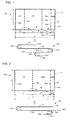
FIG. 1 shows a first sheet body forming a stack of sheets according to a first embodiment of the invention. -
FIG. 2 shows a second sheet body forming the stack of sheets according to the first embodiment. -
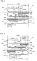
FIG. 3 shows one example of the stack of sheets according to the first embodiment, as viewed from the direction perpendicular to folding lines of the first and second sheet bodies (the direction of the width of the stack of sheets). -
FIG. 4 shows another example of the stack of sheets according to the first embodiment, as viewed from the direction perpendicular to folding lines of the first and second sheet bodies (the direction of the width of the stack of sheets). -
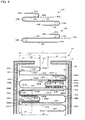
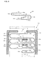
FIG. 5 shows a sheet container which contains the stack of sheets shown as the one example according to the first embodiment in a case. -
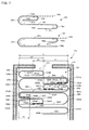
FIG. 6 shows a first sheet body and a second sheet body which form a stack of sheets according to a second embodiment of the invention, and a sheet container which contains the stack of sheets according to the second embodiment in a case. -
FIG. 7 shows a first sheet body and a second sheet body which form a stack of sheets according to a third embodiment of the invention, and a sheet container which contains the stack of sheets according to the third embodiment in a case. -
FIG. 8 shows a first sheet body and a second sheet body which form a stack of sheets according to a fourth embodiment of the invention, and a sheet container which contains the stack of sheets according to the fourth embodiment in a case. -
FIG. 9 shows a sheet body which forms a stack of sheets according to a fifth embodiment of the invention, and a sheet container which contains the stack of sheets according to the fifth embodiment in a case. -
FIG. 10 shows a sheet body which forms a stack of sheets according to a sixth embodiment of the invention, and a sheet container which contains the stack of sheets according to the sixth embodiment in a case. - First representative embodiment of the invention is now described with reference to
FIGS. 1 to 5 . In this embodiment, a stack of wet tissues is described as a representative example of a stack of sheets according to this invention.FIGS. 1 and 2 show afirst sheet body 130 and asecond sheet body 140, respectively, which form a stack ofsheets 120 according to this embodiment, as viewed from a direction of the width (a direction perpendicular to folding lines).FIGS. 3 and 4 show two different examples of the stack ofsheets 120 according to this embodiment, respectively, as viewed from the direction of the width (the direction perpendicular to folding lines).FIG. 5 shows asheet container 110 which contains the stack ofsheets 120 shown inFIG. 3 as one example according to this embodiment in acase 111, as viewed from the direction of the width (the direction perpendicular to folding lines).
As shown inFIGS. 1 and 2 , for example, awet tissue 10 is an impregnated sheet of a rectangular shape having a long side M (having a length m) and a short side N (having a length n). Naturally, the wet tissue 11 can be provided in various shapes such as a square (m=n). The impregnated sheet is formed by impregnating a base sheet with impregnating liquid. The base sheet may be, for example, a sheet made of pulp, a sheet made of pulp and thermoplastic resin, or a sheet made of nonwoven fabric. The impregnating liquid may be, for example, water or water-soluble alcohol. - The stack of
sheets 120 of this embodiment consists offirst sheet bodies 130 andsecond sheet bodies 140 which are each formed by foldingwet tissues 10.
As shown inFIG. 1 , thefirst sheet body 130 is formed by folding awet tissue 10 along afirst folding line 130b and asecond folding line 130c which extend parallel to the short side N (perpendicularly to the direction of the width) at a distance xa, xb from anend 130a on one side, along the long side M (in the direction of the width). The folding direction along thesecond folding line 130c is opposite to the folding direction along thefirst folding line 130b. For example, theend 130a on one side is folded upward (to one side in a direction perpendicular to the direction of the width) along thefirst folding line 130b, and theother end 130d is folded downward (to the other side in the direction perpendicular to the direction of the width) along thesecond folding line 130c. Thus, when viewed from the direction of the width, thefirst sheet body 130 is formed into a Z-shape having afirst piece 131 between the oneend 130a and thefirst folding line 130b, asecond piece 132 between thefirst folding line 130b and thesecond folding line 130c, and a third piece 133 between thesecond folding line 130c and theother end 130d. Thefirst sheet body 130 is further folded along anauxiliary folding line 130e extending parallel to the short side N (perpendicularly to the direction of the width) at a distance xc2 from theother end 130d along the direction of the width. In this embodiment, the folding direction along theauxiliary folding line 130e is opposite to the folding direction along thesecond folding line 130c. For example, theother end 130d is folded downward (to the other side in the direction perpendicular to the direction of the width) along theauxiliary folding line 130e. Thus, the third piece 133 of thefirst sheet body 130 is folded into afirst segment 133a and asecond segment 133b.
Thefirst sheet body 130, thefirst piece 131 of thefirst sheet body 130, thesecond piece 132 of thefirst sheet body 130, the third piece 133 (thefirst segment 133a and thesecond segment 133b) of thefirst sheet body 130, and thesecond segment 133b of the third piece 133 of thefirst sheet body 130 are features that correspond to the "first sheet body", the "first piece of the first sheet body", the "second piece of the first sheet body", the "third piece of the first sheet body" and the "auxiliary piece formed by folding an end of the piece of the first sheet body which lies on one of the opposite sides in the stacking direction", respectively, according to this invention. - As shown in
FIG. 2 , thesecond sheet body 140 is formed by folding awet tissue 10 along afolding line 140b which extends parallel to the short side N (perpendicularly to the direction of the width) at a distance ya from anend 140a on one side, along the long side M (in the direction of the width). For example, anend 140c of the other side is folded downward (to the other side in the direction perpendicular to the direction of the width) along thefolding line 140b. Thus, when viewed from the direction of the width, thesecond sheet body 140 is formed into a V-shape having afirst piece 141 between the oneend 140a and thefolding line 140b, and asecond piece 142 between thefolding line 140b and theother end 140c. Thesecond sheet body 140 is further folded along anauxiliary folding line 140e extending parallel to the short side N (perpendicularly to the direction of the width) at a distance yb2 from theother end 140c along the direction of the width. In this embodiment, the folding direction along theauxiliary folding line 140e is opposite to the folding direction along thefolding line 140b. For example, theother end 140c is folded downward (to the other side in the direction perpendicular to the direction of the width) along theauxiliary folding line 140e. Thus, thesecond piece 142 of thesecond sheet body 140 is folded into afirst segment 142a and asecond segment 142b.
Thesecond sheet body 140, thefirst piece 141 of thesecond sheet body 140, the second piece 142 (thefirst segment 142a and thesecond segment 142b) of thesecond sheet body 140, and thesecond segment 142b of thesecond sheet body 140 are features that correspond to the "second sheet body", the "fourth piece of the second first sheet body", the "fifth piece of the second first sheet body", and the "auxiliary piece formed by folding the end of the piece of the second sheet body which lies on one of the opposite sides in the stacking direction", respectively, according to this invention. - Then, the
first sheet bodies 130 and thesecond sheet bodies 140 are stacked one on another to form the stack ofsheets 120. Thefirst sheet bodies 130 and thesecond sheet bodies 140 are stacked one on another in such a manner that, when afirst sheet body 130 orsecond sheet body 140 lying on the end of the stack of sheets on one side in the stacking direction (on the upper end inFIGS. 3 and 4 ) is pulled away from the stack ofsheets 120 one by one, part of asecond sheet body 140 orfirst sheet body 130 which immediately underlies thefirst sheet body 130 orsecond sheet body 140 is also pulled away from the stack ofsheets 120.
Thefirst sheet bodies 130 and thesecond sheet bodies 140 are stacked one on another, for example, in such a manner that thefirst piece 141 and the second piece 142 (thefirst segment 142a and thesecond segment 142b) of each of thesecond sheet bodies 140 are inserted between thesecond piece 132 and the third piece 133 (thefirst segment 133a and thesecond segment 133b) of thefirst sheet body 130 on one side in the stacking direction of thesecond sheet body 140 and between thefirst piece 131 and thesecond piece 132 of thefirst sheet body 130 on the other side in the stacking direction of thesecond sheet body 140, respectively. -
FIG. 3 shows one example of the stack ofsheets 120 according to this embodiment. InFIG. 3 , a width m of thewet tissue 10 is 200 mm, a width L of the stack ofsheets 120 is 90 mm, a width xa of thefirst piece 131 of thefirst sheet body 130 is 45 mm, a width xb of thesecond piece 132 is 90 mm, a width xc1 of thefirst segment 130a is 45 mm, a width xc2 of thesecond segment 130b is 20 mm (i.e. a width xc of the third piece 133 is 65 mm), a width ya of thefirst piece 141 of thesecond sheet body 140 is 90 mm, a width yb1 of thefirst segment 142a is 90 mm, a width yb2 of thesecond segment 142b is 20 mm (i.e. a width yb of thesecond piece 142 is 110 mm).
Thefirst sheet bodies 130 and thesecond sheet bodies 140 are arranged alternately along the stacking direction (vertical direction inFIG. 3 ), when viewed from the direction perpendicular to the folding lines of the first andsecond sheet bodies 130, 140 (from the direction of the width). Further, thefirst sheet bodies 130 are arranged along the stacking direction in such orientation that the one ends 130a and the other ends 130d are alternately reversed in position with respect to a direction perpendicular to the stacking direction (to a lateral direction inFIG. 3 ). Likewise, thesecond sheet bodies 140 are arranged along the stacking direction in such orientation that the one ends 140a and the other ends 140c are alternately reversed in position with respect to the direction perpendicular to the stacking direction (to the lateral direction inFIG. 3 ).
In the following description, thefirst sheet bodies 130 which are arranged in one orientation with respect to the positions of the one ends 130a and the other ends 130d are designated by 130A (the first sheet bodies of a first group), while the otherfirst sheet bodies 130 which are arranged in the other orientation (in reversed orientation to the one orientation) are designated by 130B (the first sheet bodies of a second group). InFIG. 3 , thefirst sheet bodies 130A (the first sheet bodies of the first group) are arranged with the one ends 130aA on the left (on one side with respect to the direction perpendicular to the stacking direction) and the other ends 130dA on the right (on the other side with respect to the direction perpendicular to the stacking direction). Further, thefirst sheet bodies 130B (the first sheet bodies of the second group) are arranged with the one ends 130aB on the right (on the other side with respect to the direction perpendicular to the stacking direction) and the other ends 130dB on the left (on the one side with respect to the direction perpendicular to the stacking direction).
Likewise, thesecond sheet bodies 140 which are arranged in one orientation with respect to the positions of the one ends 140a and the other ends 140c are designated by 140A (the second sheet bodies of a first group), while the othersecond sheet bodies 140 which are arranged in the other orientation (in reversed orientation to the one orientation) are designated by 140B (the second sheet bodies of a second group). InFIG. 3 , thesecond sheet bodies 140A (the second sheet bodies of the first group) are arranged with one ends 140aA on the right (on the other side with respect to the direction perpendicular to the stacking direction) and the other ends 140cA on the left (on the one side with respect to the direction perpendicular to the stacking direction). Further, thesecond sheet bodies 140B (the second sheet bodies of the second group) are arranged with the one ends 140aB on the left (on the one side with respect to the direction perpendicular to the stacking direction) and the other ends 140cB on the right (on the other side with respect to the direction perpendicular to the stacking direction). - The
first sheet bodies second sheet bodies
In this embodiment, thefirst piece 141A of each of thesecond sheet bodies 140A is inserted between thesecond piece 132A and the third piece 133A (the first segment 133aA and the second segment 133bA), specifically between thesecond piece 132A and the first segment 133aA, of thefirst sheet body 130A on the upper side of (on one side in the stacking direction of) thesecond sheet body 140A. Further, the second piece 142A (the first segment 142aA and the second segment 142bA) of thesecond sheet body 140A is inserted between thefirst piece 131B and thesecond piece 132B of thefirst sheet body 130B on the lower side of (on the other side in the stacking direction of) thesecond sheet body 140A.
Likewise, thefirst piece 141B of thesecond sheet body 140B is inserted between thesecond piece 132B and the third piece 133B (the first segment 133aB and the second segment 133bB), specifically between thesecond piece 132B and the first segment 133aB, of thefirst sheet body 130B on the upper side of (on the one side in the stacking direction of) thesecond sheet body 140B. Further, the second piece 142B (the first segment 142aB and the second segment 142bB) of thesecond sheet body 140B is inserted between thefirst piece 131A and thesecond piece 132A of thefirst sheet body 130A on the lower side of (on the other side in the stacking direction of) thesecond sheet body 140B. - The stack of
sheets 120 of this embodiment as shown inFIG. 3 is contained in acase 111 of asheet container 110 shown inFIG. 5 . A sheet take-outopening 112 is formed in thecase 111. The first sheet bodies 130 (130A, 130B) and the second sheet bodies 140 (140A, 140B) which form the stack ofsheets 120 are taken out through the take-outopening 2 one by one. In this embodiment, the stack ofsheets 120 is contained within thecase 111 with the take-outopening 112 side of thecase 111 on the upper side (the one side in the stacking direction) inFIG. 3 . - Taking out the first sheet bodies 130 (130A, 130B) and the second sheet bodies 140 (140A, 140B) through the take-out
opening 112 of thecase 111 is now described.
In order to take out thefirst sheet body 130A lying on the upper end (on one side in the stacking direction) of the stack ofsheets 120, the one end 130aA side of thefirst sheet body 130 is pulled in an upward direction (in the direction of the one side in the stacking direction) shown by a solid arrow through the take-outopening 112 away from the stack ofsheets 120. At this time, the third piece 133A of the first sheet body 130 (particularly, the first segment 133Aa of the third piece 133A, which is placed on the one side in the stacking direction) is also pulled in the upward direction shown by a dotted arrow. In this embodiment, thefirst piece 141A of thesecond sheet body 140A which immediately underlies thefirst sheet body 130A is inserted between thesecond piece 132A and the third piece 133A (particularly, the first segment 133aA of the third piece 133A, which is placed on the one side in the stacking direction). Therefore, when the third piece 133A of thefirst sheet body 130A is pulled in the upward direction shown by the dotted arrow, thefirst piece 141A of thesecond sheet body 140A is also pulled upward by friction between the first segment 133aA of the third piece 133A of thefirst sheet body 130A and thefirst piece 141A of thesecond sheet body 140A. In this case, when the first sheet bodies 130 (130A, 130B) and second sheet bodies 140 (140A, 140B) shown inFIG. 3 are used, an overlapping width w of an overlapping region W between the first segment 133aA of the third piece 133A of thefirst sheet body 130A and thefirst piece 141A of thesecond sheet body 140A is 45 mm. Therefore, friction which is related to the overlapping width w of the overlapping region W is produced between the first segment 133aA of the third piece 133A of thefirst sheet body 130A and thefirst piece 141A of thesecond sheet body 140A. Then, when thefirst sheet body 130A is taken out through the take-outopening 112, the one end 140aA side of thefirst piece 141A of thesecond sheet body 140A is partially exposed (drawn out) through the take-outopening 112. - Next, in order to take out the
second sheet body 140A, the drawn-out part of the one end 140aA side of thefirst piece 141A of thesecond sheet body 140A is pulled in an upward direction shown by a solid arrow away from the stack ofsheets 120. At this time, the second piece 142A (particularly, the first segment 142aA of the second piece 142A, which is placed on the one side in the stacking direction) of thesecond sheet body 140A is also pulled in the upward direction shown by a dotted arrow. In this embodiment, the second piece 142A (particularly, the first segment 142aA) of thesecond sheet body 140A is inserted between thefirst piece 131B and thesecond piece 132B of thefirst sheet body 130B. Therefore, when the second piece 142A (particularly, the first segment 142aA) of thesecond sheet body 140A is pulled in the upward direction shown by the dotted arrow, the one end 130aB side of thefirst piece 131B of thefirst sheet body 130B is also pulled upward by friction between the first segment 142aA of the second piece 142A of thesecond sheet body 140A and thefirst piece 131B of thefirst sheet body 130B. In this case, when the first sheet bodies 130 (130A, 130B) and second sheet bodies 140 (140A, 140B) shown inFIG. 3 are used, an overlapping width w of an overlapping region W between the first segment 142aA of the second piece 142A of thesecond sheet body 140A and thefirst piece 131B of thefirst sheet body 130B is 45 mm. Therefore, friction which is related to the overlapping width w of the overlapping region W is produced between the first segment 142aA of the second piece 142A of thesecond sheet body 140A and thefirst piece 131B of thefirst sheet body 130B. Then, when thesecond sheet body 140A is taken out through the take-outopening 112, the one end 130aB side of thefirst piece 131B of thefirst sheet body 130B is partially exposed (drawn out) through the take-outopening 112.
In the same manner, when the drawn-out part of the one end 130aB side of thefirst piece 131B of thefirst sheet body 130B is pulled upward, thefirst sheet body 130B is taken out, and at the same time, the one end 140aB side of thefirst piece 141B of thesecond sheet body 140B to be taken out next is partially exposed (drawn out) through the take-outopening 112. Thereafter, when the drawn-out part of the one end 140aB side of thefirst piece 141B of thesecond sheet body 140B is pulled upward, thesecond sheet body 140B is taken out, and at the same time, the one end 130aA side of thefirst piece 131A of thefirst sheet body 130A to be taken out next is partially exposed (drawn out) through the take-outopening 112. - When the stack of
sheets 120 is formed as described above by the first sheet bodies 130 (130A, 130B) and the second sheet bodies 140 (140A, 140B) which are dimensioned as shown inFIG. 3 , even if the sheet width m is 200 mm and the width L of the stack ofsheets 120 is 90 mm (or even if n > 2m), the overlapping width w of the overlapping region W between the first sheet body 130 (130A, 130B) and the second sheet body 140 (140A, 140B) can be set to the desired width of 45 mm.
Further, in this embodiment, the auxiliary pieces (e.g. 133bA and 142bA, 133bB and 142bB) of thefirst sheet body 130 and thesecond sheet body 140 which are adjacent to each other in the stacking direction, the auxiliary pieces (e.g. 133bA and 133bB ) of thefirst sheet bodies 130 which are adjacent to each other in the stacking direction, and the auxiliary pieces (e.g. 142bA and 142bB ) of thesecond sheet bodies 140 which are adjacent to each other in the stacking direction do not overlap one another. Therefore, the stack ofsheets 120 can be prevented from being partially increased in height. -
FIG. 4 shows another example of the stack ofsheets 120 formed by using differently dimensioned first sheet bodies 130 (130A, 130B) and second sheet bodies 140 (140A, 140B).
InFIG. 4 , the width m of thewet tissue 10 is 200 mm, the width L of the stack ofsheets 120 is 90 mm, the width xa of thefirst piece 131 of thefirst sheet body 130 is 45 mm, the width xb of thesecond piece 132 is 90 mm, the width xc1 of thefirst segment 130a is 35 mm, the width xc2 of thesecond segment 130b is 30 mm (i.e. the width xc of the third piece 133 is 65 mm), the width ya of thefirst piece 141 of thesecond sheet body 140 is 90 mm, the width yb1 of thefirst segment 142a is 80 mm, the width yb2 of thesecond segment 142b is 30 mm (i.e. the width yb of thesecond piece 142 is 110 mm).
When the first sheet bodies 130 (130A, 130B) and the second sheet bodies 140 (140A, 140B) which are dimensioned as shown inFIG. 4 are used, the overlapping width w of the overlapping region W between the first sheet body 130 (130A, 130B) and the second sheet body 140 (140A, 140B) can be set to a desired width of 35 mm, even if the sheet width m is 200 mm and the width L of the stack ofsheets 120 is 90 mm (or even if n > 2m). - Second representative embodiment of a stack of sheets and a sheet container according to this invention is now described with reference to
FIG. 6 .
A stack ofsheets 220 of this embodiment is formed byfirst sheet bodies 230 andsecond sheet bodies 240.
Like thefirst sheet body 130 of the first embodiment, thefirst sheet body 230 is formed by folding a sheet along afirst folding line 230b and asecond folding line 230c at a distance xa, xb from anend 230a on one side in the direction of the width. The folding direction along thesecond folding line 230c is opposite to the folding direction along thefirst folding line 230b. Thus, thefirst sheet body 230 is formed into a Z-shape having afirst piece 231, asecond piece 232 and a third piece 233. Thefirst sheet body 230 is further folded along anauxiliary folding line 230e at a distance xc2 from theother end 230d along the direction of the width. In this embodiment, the folding direction along theauxiliary folding line 230e is the same as the folding direction along thesecond folding line 230c. For example, theother end 230d is folded upward (to the one side in the direction perpendicular to the direction of the width) along theauxiliary folding line 230e. Thus, the third piece 233 of thefirst sheet body 230 is folded into afirst segment 233a and asecond segment 233b.
Like thesecond sheet body 140 of the first embodiment, thesecond sheet body 240 is folded along afolding line 240b at a distance ya from anend 240a on one side in the direction of the width. Thus, thesecond sheet body 240 is formed into a V-shape having afirst piece 241 and a second piece 242. Thesecond sheet body 240 is further folded along anauxiliary folding line 240e at a distance yb2 from theother end 240c along the direction of the width. In this embodiment, the folding direction along theauxiliary folding line 240e is the same as the folding direction along thefolding line 240b. For example, theother end 240c is folded upward (to the one side in the direction perpendicular to the direction of the width) along theauxiliary folding line 240e. Thus, the second piece 242 of thesecond sheet body 240 is folded into afirst segment 242a and asecond segment 242b.
Then, like in the first embodiment, thefirst sheet bodies 230 and thesecond sheet bodies 240 are stacked one on another in such a manner that thefirst piece 241 and the second piece 242 (thefirst segment 242a and thesecond segment 242b) of each of thesecond sheet bodies 240 are inserted between thesecond piece 232 and the third piece 233 (thefirst segment 233a and thesecond segment 233b) of thefirst sheet body 230 on one side in the stacking direction of thesecond sheet body 240 and between thefirst piece 231 and thesecond piece 232 of thefirst sheet body 230 on the other side in the stacking direction of thesecond sheet body 240, respectively. - In this embodiment, when a
first sheet body 230A (230B) is taken out of acase 211 through a take-outopening 212, one end 240aA (240aB) side of a first piece 241A (241B) of asecond sheet body 240A (240B) is partially exposed through the take-outopening 212 by friction between a second segment 233bA (233bB) of a third piece 233A (233B) of thefirst sheet body 230A (230B) and a first piece 241A (241B) of thesecond sheet body 240A (240B).
Further, when thesecond sheet body 240A (240B) is taken out of thecase 211 through the take-outopening 212, one end 230aB (230aA) side of a first piece 231B (231A) of thefirst sheet body 230B (230A) is partially exposed through the take-outopening 212 by friction between a second segment 242bA (242bB) of a second piece 242A (242B) of thesecond sheet body 240A (240B) and a first piece 231B (231A) of thefirst sheet body 230B (230A).
In this embodiment, too, the overlapping width w of the overlapping region W between thefirst sheet body 230 and thesecond sheet body 240 can be reduced by adjusting the length of thesecond segment 233b (on theother end 230d side) of the third piece 233 of thefirst sheet body 230 and the length of thesecond segment 242b (on theother end 240c side) of the second piece 242 of thesecond sheet body 240.
Further, the auxiliary pieces (e.g. 242bA and 232bA, 242bB and 232bB) of thefirst sheet body 230 and thesecond sheet body 240 which are adjacent to each other in the stacking direction, the auxiliary pieces (e.g. 242bA and 232bB ) of thefirst sheet bodies 230 which are adjacent to each other in the stacking direction, and the auxiliary pieces (e.g. 232bA and 232bB ) of thesecond sheet bodies 240 which are adjacent to each other in the stacking direction do not overlap one another. Therefore, the stack ofsheets 220 can be prevented from being partially increased in height. - Third representative embodiment of a stack of sheets and a sheet container according to this invention is now described with reference to
FIG. 7 .
Afirst sheet body 330 is folded along afirst folding line 330b and asecond folding line 330c which extend parallel to a short side N (perpendicularly to the direction of the width) at a distance xa, xb from anend 330a on one side in the direction of the width of thewet tissue 10. The folding direction along thesecond folding line 330c is opposite to the folding direction along thefirst folding line 330b. For example, the oneend 330a is folded upward (to one side in a direction perpendicular to the direction of the width) along thefirst folding line 330b, and theother end 330d is folded downward (to the other side in the direction perpendicular to the direction of the width) along thesecond folding line 330c. Thus, thefirst sheet body 330 is formed into a Z-shape having a first piece 331, asecond piece 332 and athird piece 333. Thefirst sheet body 330 is further folded along anauxiliary folding line 330e extending perpendicularly to the direction of the width at a distance xa1 from the oneend 330a along the direction of the width of thewet tissue 10. In this embodiment, the folding direction along theauxiliary folding line 330e is the same as the folding direction along thefirst folding line 330b. For example, the oneend 330a is folded downward (to the other side in the direction perpendicular to the direction of the width) along theauxiliary folding line 330e. Thus, the first piece 331 of thefirst sheet body 330 is folded into afirst segment 331a and asecond segment 331b.
Thefirst sheet body 330, the first piece 331 (thefirst segment 331a and thesecond segment 331b) of thefirst sheet body 330, thesecond piece 332 of thefirst sheet body 330, thethird piece 333 of thefirst sheet body 330, and thefirst segment 331a of the first piece 331 of thefirst sheet body 330 are features that correspond to the "first sheet body", the "first piece of the first sheet body", the "second piece of the first sheet body", the "third piece of the first sheet body" and the "auxiliary piece formed by folding the end of the piece of the first sheet body which lies on one of the opposite sides in the stacking direction", respectively, according to this invention. - A
second sheet body 340 is folded along afolding line 340b extending perpendicularly to the direction of the width at a distance ya from anend 340a on one side in the direction of the width of thewet tissue 10. Thus, thesecond sheet body 340 is formed into a V-shape having a first piece 341 and asecond piece 342. Thesecond sheet body 340 is further folded along an auxiliary folding line 340e extending perpendicularly to the direction of the width at a distance yb1 from the oneend 340a along the direction of the width. In this embodiment, the folding direction along the auxiliary folding line 340e is opposite to the folding direction along thefolding line 340b. For example, theother end 340c is folded downward (to the other side in the direction perpendicular to the direction of the width) along the auxiliary folding line 340e. Thus, the first piece 341 of thesecond sheet body 340 is folded into afirst segment 341a and asecond segment 341b.
Thesecond sheet body 340, the first piece 341 (thefirst segment 341a and thesecond segment 341b) of thesecond sheet body 340, thesecond piece 342 of thesecond sheet body 340, and thefirst segment 341b of thesecond sheet body 340 are features that correspond to the "second sheet body", the "fourth piece of the second first sheet body", the "fifth piece of the second first sheet body", and the "auxiliary piece formed by folding the end of the piece of the second sheet body which lies on one of the opposite sides in the stacking direction", respectively, according to this invention. - Then, like in the first embodiment, the
first sheet bodies 330 and thesecond sheet bodies 340 are stacked one on another in such a manner that the first piece 341 (thefirst segment 341a and thesecond segment 341b) and the second piece 242 of each of thesecond sheet bodies 340 are inserted between thesecond piece 332 and thethird piece 333 of thefirst sheet body 330 on one side in the stacking direction of thesecond sheet body 340 and between the first piece 331 (thefirst segment 331a and thesecond segment 331b) and thesecond piece 232 of thefirst sheet body 330 on the other side in the stacking direction of thesecond sheet body 340, respectively. - In this embodiment, when a
first sheet body 330A (330B) is taken out of acase 311 through a take-outopening 312, a first segment 341aA (341aB) of a first piece 341A (341B) of asecond sheet body 340A (340B) is exposed through the take-outopening 312 by friction between athird piece 333A (333B) of thefirst sheet body 330A (330B) and a first segment 341aA (341aB) of a first piece 341A (341B) of thesecond sheet body 340A (340B).
Further, when thesecond sheet body 340A (340B) is taken out of thecase 311 through the take-outopening 312, a first segment 331aB (331aA) of a first piece 331B (331A) of thefirst sheet body 330B (330A) is exposed through the take-outopening 312 by friction between asecond piece 342A (342B) of thesecond sheet body 340A (340B) and a first segment 331aB (331aA) of a first piece 331B (331A) of thefirst sheet body 330A (330B).
In this embodiment, too, the overlapping width w of the overlapping region W between thefirst sheet body 330 and thesecond sheet body 340 can be reduced by adjusting the length of the first segment (auxiliary piece) 331a of the first piece 331 of thefirst sheet body 330 and the length of the second segment (auxiliary piece) 242b of thesecond piece 342 of thesecond sheet body 340.
Further, the auxiliary pieces (e.g. 331aB and 341aA, 331aA and 341aB) of thefirst sheet body 330 and thesecond sheet body 340 which are adjacent to each other in the stacking direction, the auxiliary pieces (e.g. 341aA and 341aB ) of thefirst sheet bodies 330 which are adjacent to each other in the stacking direction, and the auxiliary pieces (e.g. 331aB and 331aA) of thesecond sheet bodies 340 which are adjacent to each other in the stacking direction do not overlap one another. Therefore, the stack ofsheets 320 can be prevented from being partially increased in height. - Fourth representative embodiment of a stack of sheets and a sheet container according to this invention is now described with reference to
FIG. 8 .
Like thefirst sheet body 330 in the third embodiment, afirst sheet body 430 is folded along afirst folding line 430b and asecond folding line 430c at a distance xa, xb from anend 430a on one side in the direction of the width. The folding direction along thesecond folding line 430c is opposite to the folding direction along thefirst folding line 430b. Thus, thefirst sheet body 430 is formed into a Z-shape having a first piece 431, asecond piece 432 and athird piece 433. Thefirst sheet body 430 is further folded along anauxiliary folding line 430e at a distance xa1 from the oneend 430a along the direction of the width. In this embodiment, the folding direction along theauxiliary folding line 430e is opposite to the folding direction along thefirst folding line 430b. For example, the oneend 430a is folded upward (to the one side in the direction perpendicular to the direction of the width) along theauxiliary folding line 430e. Thus, the first piece 431 of thefirst sheet body 430 is folded into afirst segment 431a and asecond segment 431b.
Like thesecond sheet body 340 in the third embodiment, asecond sheet body 440 is folded along afolding line 440b at a distance ya from anend 440a on one side in the direction of the width. Thus, thesecond sheet body 440 is formed into a V-shape having a first piece 441 and asecond piece 442. Thesecond sheet body 440 is further folded along anauxiliary folding line 440e at a distance yb1 from the oneend 440a along the direction of the width. In this embodiment, the folding direction along theauxiliary folding line 440e is opposite to the folding direction along thefolding line 440b. For example, the oneend 440a is folded upward (to the one side in the direction perpendicular to the direction of the width) along theauxiliary folding line 440e. Thus, the first piece 441 of thesecond sheet body 440 is folded into afirst segment 441a and asecond segment 441b.
Then, like in the third embodiment, thefirst sheet bodies 430 and thesecond sheet bodies 440 are stacked one on another in such a manner that the first piece 441 (thefirst segment 441a and thesecond segment 441b) and thesecond piece 442 of each of thesecond sheet bodies 440 are inserted between thesecond piece 432 and thethird piece 433 of thefirst sheet body 430 on one side in the stacking direction of thesecond sheet body 440 and between the first piece 431 (thefirst segment 431a and thesecond segment 431b) and thesecond piece 432 of thefirst sheet body 430 on the other side in the stacking direction of thesecond sheet body 440, respectively. - In this embodiment, when a
first sheet body 430A (430B) is taken out of acase 411 through a take-outopening 412, one end 440aA (440aB) side of a second segment 441bA (441bB) of a first piece 441A (441B) of asecond sheet body 440A (440B) is partially exposed through the take-outopening 412 by friction between athird piece 433A (433B) of thefirst sheet body 430A (430B) and a second segment 441bA (441bB) of a first piece 441A (441B) of thefirst sheet body 430A (430B).
Further, when thesecond sheet body 440A (440B) is taken out of thecase 411 through the take-outopening 412, a second segment 431bB (431bA) of a first piece 431B (431A) of thefirst sheet body 430B (430A) is exposed through the take-outopening 412 by friction between a second segment 442bA (442bB) of asecond piece 442A (442B) of thesecond sheet body 440A (440B) and a second segment 431bB (431bA) of a first piece 431B (431A) of thefirst sheet body 430A (430B).
In this embodiment, too, the overlapping width w of the overlapping region W between thefirst sheet body 430 and thesecond sheet body 440 can be reduced by adjusting the length of thefirst segment 431a (on the oneend 430a side) of the first piece 431 of thefirst sheet body 430 and the length of thefirst segment 441a (on the oneend 440a side) of the first piece 441 of thesecond sheet body 440. - Fifth representative embodiment of a stack of sheets and a sheet container according to this invention is now described with reference to
FIG. 9 .
In this embodiment, the stack of sheets is formed only bysheet bodies 530. Each of thesheet bodies 530 is folded along afirst folding line 530b and asecond folding line 530c which extend perpendicularly to the direction of the width at a distance xa, xb from anend 530a on one side in the direction of the width of thewet tissue 10. The folding direction along thesecond folding line 530c is the same as the folding direction along thefirst folding line 530b. For example, the oneend 530a is folded upward (to one side in a direction perpendicular to the direction of the width) along thefirst folding line 530b, and theother end 530d is folded downward (to the other side in the direction perpendicular to the direction of the width) along thesecond folding line 530c. Thus, thesheet body 530 is formed into a Z-shape having afirst piece 531, asecond piece 532 and a third piece 533. Thesheet body 530 is further folded along anauxiliary folding line 530e extending perpendicularly to the direction of the width at a distance xc2 from theother end 530d along the direction of the width. In this embodiment, the folding direction along theauxiliary folding line 530e is opposite to the folding direction along thesecond folding line 530c. For example, theother end 530d is folded downward (to the other side in the direction perpendicular to the direction of the width) along theauxiliary folding line 530e. Thus, the third piece 533 of thesheet body 530 is folded into afirst segment 533a and asecond segment 533b.
Then, thesheet bodies 530 are stacked one on another in such a manner that thefirst piece 531 of each of thesheet bodies 530 is inserted between thesecond piece 532 and the third piece 533 (thefirst segment 533a and thesecond segment 533b) of theother sheet body 530 on one side in the stacking direction of thesheet body 530. - In this embodiment, when the
sheet body 530 is taken out of acase 511 through a take-outopening 512, oneend 530a side of thefirst piece 531 of thesheet body 530 is partially exposed through the take-outopening 512 by friction between the third piece 533 (particularly, thesecond segment 533b) of thesheet body 530 to be taken out and thefirst piece 532 of theother sheet body 530.
In this embodiment, too, the overlapping width w of the overlapping region W between thesheet bodies 530 can be reduced by adjusting the length of thesecond segment 533b (on theother end 530d side) of the third piece 533 of thesheet body 530. - Sixth representative embodiment of a stack of sheets and a sheet container according to this invention is now described with reference to
FIG. 10 .
In this embodiment, like in the fifth embodiment, the stack of sheets is formed only bysheet bodies 630 each of which is formed into a Z-shape having afirst piece 631, asecond piece 632 and a third piece 633. Thesheet body 630 is further folded along anauxiliary folding line 630e extending perpendicularly to the direction of the width at a distance xc2 from anend 630d on the other side along the direction of the width. In this embodiment, the folding direction along theauxiliary folding line 630e is opposite to the folding direction along asecond folding line 630c. For example, theother end 630d is folded downward (to the other side in the direction perpendicular to the direction of the width) along theauxiliary folding line 630e. Thus, the third piece 633 of thesheet body 630 is folded into afirst segment 633a and asecond segment 633b.
Then, like in the fifth embodiment, thesheet bodies 630 are stacked one on another in such a manner that thefirst piece 631 of each of thesheet bodies 630 is inserted between thesecond piece 632 and the third piece 633 (thefirst segment 633a and thesecond segment 633b) of theother sheet body 630 on one side in the stacking direction of thesheet body 630. - In this embodiment, when the
sheet body 630 is taken out of acase 611 through a take-outopening 612, oneend 630a side of thefirst piece 631 of thesheet body 630 is partially exposed through the take-outopening 612 by friction between the third piece 633 (particularly, thefirst segment 633a) of thesheet body 630 to be taken out and thefirst piece 632 of theother sheet body 630.
In this embodiment, too, the overlapping width w of the overlapping region W between thesheet bodies 630 can be reduced by adjusting the length of thesecond segment 633b (on theother end 630d side) of the third piece 633 of thesheet body 630. - In the fifth and six embodiments, the third piece 533, 633 of the
sheet body
Further, in the above-described embodiments, Z-shaped or V-shaped sheet bodies are stacked one on another to form a stack of sheets, but the shape of the sheet bodies can be appropriately selected.
As described above, in this invention, when a plurality of sheet bodies of one or more kinds each formed by folding a sheet are stacked one on another in order to form a stack of sheets, an auxiliary piece (segment) is formed by folding an end of the piece of the sheet body which lies on one of the opposite sides in the stacking direction. Friction in the overlapping region between the sheet bodies can be reduced by adjusting the length of the auxiliary piece, so that the sheets can be taken out with stability. In this case, by folding the end of the piece to form the auxiliary piece, a gap is created on the side of the end. As a result, liquid membrane (e.g. water membrane) with which the sheet bodies (sheets) lying on the both sides of the gap in the stacking direction are impregnated is destroyed, so that adhesion between the sheet bodies via the liquid membrane is deteriorated. Therefore, the sheet bodies can be prevented from being drawn out together with a sheet to be taken out next. Further, the technique of the invention is particularly effective in reducing the width L of the stack of sheets to half of the width m of the sheets or smaller. - The invention is not limited to the constructions of the above-described embodiments, but rather, may be added to, changed, replaced with alternatives or otherwise modified.
In the above embodiment, a technique of stacking wet tissues one on another is described, but the technique described herein can be applied to stacking of various kinds of sheets.
The sheet bodies for forming a stack of sheets can have various shapes which allow a sheet lying on the end on one side of the stack of sheets to be taken out continuously one by one.
Further, also with a construction in which the auxiliary sheets of sheet bodies adjacent to each other in the stacking direction (e.g. the auxiliary sheets of the first and second sheet bodies) do not overlap one another in the stacking direction, the stack of sheets can be prevented from being partially increased in height.
Each of the constructions described in the above embodiment can be used by itself or in combination of appropriately selected ones of the constructions. -
- 10 wet tissue (sheet)
- 130, 130A, 130B, 230A, 230B, 330A, 330B, 430A, 430B first sheet body
- 140, 140A, 140B, 240A, 240B, 340A, 340B, 440A, 440B second sheet body
- 130a, 130d, 130aA, 130dA, 130aB, 130dB, 140a, 140c, 140aA, 140cA, 140aB, 140cB,
- 230a, 230d, 230aA, 230dA, 230aB, 230dB, 240a, 240c, 240aA, 240cA, 240aB, 240cB,
- 330a, 330d, 330aA, 330dA, 330aB, 330dB, 340a, 340c, 340aA, 340cA, 340aB, 340cB,
- 430a, 430d, 430aA, 430dA, 430aB, 430dB, 440a, 440c, 440aA, 440cA, 440aB, 440cB end
- 130b, 130c, 130e, 130bA, 130cA, 130eA, 130bB, 130cB, 130eB, 140b, 140e, 140bA,
- 140eA, 140bB, 140eB, 230b, 230c, 230e, 230bA, 230cA, 230eA, 230aB, 230bB, 230cB,
- 230eB, 240b, 240e, 240bA, 240eA, 240bB, 240eB, 330b, 330c, 330e, 330bA, 330cA,
- 330eA, 330bB, 330cB, 330eB, 340b, 340e, 340bA, 340eA, 340bB, 340eB, 430b, 430c,
- 430e, 430bA, 430cA, 430eA, 430bB, 430cB, 440eB, 440b, 440e, 440bA, 440eA, 440bB,
- 440eB, 530b, 530c, 530e, 630b, 630c, 630e folding line
- 110, 210, 310, 410, 510, 610 sheet container
- 111, 211, 311, 411, 511, 611 case
- 112, 212, 312, 412, 512, 612 take-out opening
- 530, 630 sheet body
- m width of a sheet
- L width of a stack of sheets
Claims (7)
- A stack of sheets comprising:sheet bodies each of which is formed by folding a sheet and has a plurality of pieces between both ends of the sheet body,the sheet bodies being stacked one on another in such a manner that one of the plurality of pieces of each of the sheet bodies on one side in a stacking direction and another piece on the other side are inserted between pieces of an adjacent sheet body on one side in the stacking direction with respect to the sheet body and between pieces of an adjacent sheet body on the other side in the stacking direction, respectively, wherein:an auxiliary piece is formed by folding an end of the piece of the sheet body which lies on one of the opposite sides in the stacking direction.
- A stack of sheets comprising:first sheet bodies each formed by folding a sheet, and having a first piece, a second piece and a third piece between both ends of the sheet body, the first piece and the third piece being folded in opposite directions to each other with respect to the second piece,second sheet bodies each formed by folding a sheet, and having a fourth piece and a fifth piece between both ends of the sheet body,the first sheet bodies and the second sheet bodies being alternately stacked one on another in such a manner that the fourth piece and the fifth piece of each of the second sheet bodies are inserted between the second piece and the third piece of a first sheet body adjacent to the second sheet body on one side in a stacking direction and between the first piece and the second piece of a first sheet body which is adjacent to the second sheet body on the other side in the stacking direction, respectively, wherein:an auxiliary piece is formed by folding an end of the piece of each of the first and second sheet bodies which lies on one of the opposite sides in the stacking direction.
- The stack of sheets as defined in claim 2, wherein the auxiliary pieces of the first sheet bodies which are adjacent in the stacking direction or the auxiliary pieces of the second sheet bodies which are adjacent in the stacking direction do not overlap one another in the stacking direction.
- The stack of sheets as defined in any one of claims 1 to 3, wherein the auxiliary pieces of the sheet bodies adjacent in the stacking direction do not overlap one another in the stacking direction.
- A stack of sheets comprising:sheet bodies each formed by folding a sheet, and having a first piece, a second piece and a third piece, the first piece and the third piece being folded in opposite directions to each other with respect to the second piece,the sheet bodies being alternately stacked one on another in such a manner that the first piece and the third piece of each of the sheet bodies are inserted between the second piece and the third piece of a sheet body adjacent to the sheet body on one side in a stacking direction and between the first piece and the second piece of a sheet body adjacent to the sheet body on the other side in the stacking direction, respectively, wherein:an auxiliary piece is formed by folding an end of the piece of the sheet body which lies on one of the opposite sides in the stacking direction.
- The stack of sheets as defined in any one of claims 1 to 5, wherein wet tissues are used as the sheets.
- A sheet container comprising a case with a take-out opening and a stack of sheets which is formed by stacking a plurality of sheets one on another and contained within the case, and from which sheets forming the stack of sheets are taken out one by one through the take-out opening of the case, wherein:the stack of sheets as defined in any one of claims 1 to 6 is used as the stack of sheets.
Applications Claiming Priority (2)
| Application Number | Priority Date | Filing Date | Title |
|---|---|---|---|
| JP2008094290A JP5143612B2 (en) | 2008-03-31 | 2008-03-31 | Sheet stack and sheet storage device |
| PCT/JP2009/056522 WO2009123131A1 (en) | 2008-03-31 | 2009-03-30 | Stacked sheet body and sheet storing device |
Publications (3)
| Publication Number | Publication Date |
|---|---|
| EP2275015A1 true EP2275015A1 (en) | 2011-01-19 |
| EP2275015A4 EP2275015A4 (en) | 2012-08-01 |
| EP2275015B1 EP2275015B1 (en) | 2016-03-23 |
Family
ID=41135505
Family Applications (1)
| Application Number | Title | Priority Date | Filing Date |
|---|---|---|---|
| EP09728963.1A Active EP2275015B1 (en) | 2008-03-31 | 2009-03-30 | Stacked sheet body and sheet storing device |
Country Status (6)
| Country | Link |
|---|---|
| US (1) | US8393496B2 (en) |
| EP (1) | EP2275015B1 (en) |
| JP (1) | JP5143612B2 (en) |
| CN (1) | CN101980645B (en) |
| TW (1) | TW201000059A (en) |
| WO (1) | WO2009123131A1 (en) |
Cited By (1)
| Publication number | Priority date | Publication date | Assignee | Title |
|---|---|---|---|---|
| GB2546377A (en) * | 2015-11-20 | 2017-07-19 | Nice-Pak Int Ltd | Stack of interleaved wipes |
Families Citing this family (5)
| Publication number | Priority date | Publication date | Assignee | Title |
|---|---|---|---|---|
| JPH0621731B2 (en) | 1986-10-23 | 1994-03-23 | 三洋電機株式会社 | Cooling / heating switching type absorption chiller / heater |
| US9017790B2 (en) | 2011-03-02 | 2015-04-28 | Cascades Canada Ulc | Absorbent sheet products and method for folding same |
| JP6150484B2 (en) * | 2012-09-28 | 2017-06-21 | 大王製紙株式会社 | Container with wet tissue laminate |
| JP7822830B2 (en) * | 2022-03-02 | 2026-03-03 | ピジョン株式会社 | Hygienic sheet laminate |
| CN116081097A (en) * | 2022-10-21 | 2023-05-09 | 浙江海龙新型建材有限公司 | Method for laminating coated fiber cement boards |
Family Cites Families (13)
| Publication number | Priority date | Publication date | Assignee | Title |
|---|---|---|---|---|
| US3207360A (en) * | 1961-07-28 | 1965-09-21 | Scott Paper Co | Sheet packaging arrangements |
| JP3308304B2 (en) | 1992-07-06 | 2002-07-29 | 三井化学株式会社 | Molding method of molding material and molding device |
| JP2951187B2 (en) * | 1994-01-26 | 1999-09-20 | 克 米山 | Continuous take-out structure of multiple waist folded wet test shoes |
| US5565258A (en) * | 1995-03-02 | 1996-10-15 | Kimberly-Clark Corporation | Folded absorbent paper product and method |
| US6213344B1 (en) * | 1997-05-23 | 2001-04-10 | The Procter & Gamble Company | Folding and stacking configuration for wet wipes |
| ES2181947T3 (en) * | 1997-05-23 | 2003-03-01 | Procter & Gamble | CONFIGURATION OF FOLDING AND STACKING FOR WET TOWELS THAT HAVE AN IMPROVED DISPENSATION AND INDIVIDUAL SEPARATION OF THE WET TOWELS OF LA PILA. |
| JP3485470B2 (en) * | 1998-08-11 | 2004-01-13 | ユニ・チャーム株式会社 | Wet tissue laminate and products containing it |
| JP3730105B2 (en) * | 2000-10-04 | 2005-12-21 | ユニ・チャーム株式会社 | Sheet package |
| US6685050B2 (en) * | 2001-12-20 | 2004-02-03 | Kimberly-Clark Worldwide, Inc. | Folded sheet product, dispenser and related assembly |
| JP3819914B2 (en) * | 2004-03-31 | 2006-09-13 | 東亜機工株式会社 | Sheet laminate |
| CN2868904Y (en) * | 2005-07-01 | 2007-02-14 | 永丰馀造纸股份有限公司 | Double-folded continuous-fetching type face tissue |
| JP2007159880A (en) * | 2005-12-15 | 2007-06-28 | Shinei Giken:Kk | Multi-folded wet tissue paper |
| US8097326B2 (en) * | 2008-10-27 | 2012-01-17 | Paper Converting Machine Company | Stack comprising multi-folded four panel sheets and folding boards therefor |
-
2008
- 2008-03-31 JP JP2008094290A patent/JP5143612B2/en active Active
-
2009
- 2009-03-30 CN CN200980111549.5A patent/CN101980645B/en not_active Expired - Fee Related
- 2009-03-30 US US12/935,305 patent/US8393496B2/en not_active Expired - Fee Related
- 2009-03-30 EP EP09728963.1A patent/EP2275015B1/en active Active
- 2009-03-30 TW TW098110452A patent/TW201000059A/en unknown
- 2009-03-30 WO PCT/JP2009/056522 patent/WO2009123131A1/en not_active Ceased
Cited By (3)
| Publication number | Priority date | Publication date | Assignee | Title |
|---|---|---|---|---|
| GB2546377A (en) * | 2015-11-20 | 2017-07-19 | Nice-Pak Int Ltd | Stack of interleaved wipes |
| GB2546377B (en) * | 2015-11-20 | 2021-08-04 | Nice Pak International Ltd | Stack of interleaved wipes |
| US11375860B2 (en) | 2015-11-20 | 2022-07-05 | Nice-Pak International Limited | Stack of interleaved wipes |
Also Published As
| Publication number | Publication date |
|---|---|
| CN101980645B (en) | 2015-06-03 |
| JP2009240725A (en) | 2009-10-22 |
| CN101980645A (en) | 2011-02-23 |
| US8393496B2 (en) | 2013-03-12 |
| US20110101592A1 (en) | 2011-05-05 |
| JP5143612B2 (en) | 2013-02-13 |
| EP2275015B1 (en) | 2016-03-23 |
| EP2275015A4 (en) | 2012-08-01 |
| WO2009123131A1 (en) | 2009-10-08 |
| TW201000059A (en) | 2010-01-01 |
Similar Documents
| Publication | Publication Date | Title |
|---|---|---|
| EP2275015B1 (en) | Stacked sheet body and sheet storing device | |
| CA2330098C (en) | A tissue box | |
| EP2233406A1 (en) | Sanitary tissue paper containing box | |
| KR101414545B1 (en) | Household paper storage box | |
| EP0747313A1 (en) | Multiple folded paper for continuous disposal | |
| JP2002102106A (en) | Sheet packaging | |
| EP2305086B1 (en) | Stacked sheet body and sheet storing device | |
| ES2931183T3 (en) | Stack of sheets of paper, dispenser having such a stack, and method of forming such a stack | |
| MX2013009925A (en) | Compressed tissue carton. | |
| RU2013121579A (en) | STACK OF SANITARY-HYGIENIC PAPER AND ITS DISTRIBUTION | |
| US6745917B2 (en) | Sheet package | |
| US5901875A (en) | Separator for use in packets of papers | |
| JP5894000B2 (en) | Packaging boxes and cardboard sheets | |
| JP2004075172A (en) | Corrugated cardboard tray | |
| US10947029B2 (en) | Flexible sheet dispenser | |
| JP7492883B2 (en) | Sheet bundle | |
| JP3238700U (en) | box sheet | |
| CN216876139U (en) | Drawing-out type tissue packaging body | |
| JP7729533B2 (en) | Packaging bag and sheet packaging body | |
| JP2004261352A (en) | Home use tissue paper storage box | |
| AU5839899A (en) | Transport unit | |
| JP2023120613A (en) | box sheet | |
| KR20130004136U (en) | Tissue case | |
| WO2019082438A1 (en) | Storage container, wound body-containing storage container, and cutting blade | |
| JP2011184058A (en) | Pushing-up body and storage case using the same |
Legal Events
| Date | Code | Title | Description |
|---|---|---|---|
| PUAI | Public reference made under article 153(3) epc to a published international application that has entered the european phase |
Free format text: ORIGINAL CODE: 0009012 |
|
| 17P | Request for examination filed |
Effective date: 20101018 |
|
| AK | Designated contracting states |
Kind code of ref document: A1 Designated state(s): AT BE BG CH CY CZ DE DK EE ES FI FR GB GR HR HU IE IS IT LI LT LU LV MC MK MT NL NO PL PT RO SE SI SK TR |
|
| AX | Request for extension of the european patent |
Extension state: AL BA RS |
|
| A4 | Supplementary search report drawn up and despatched |
Effective date: 20120628 |
|
| RIC1 | Information provided on ipc code assigned before grant |
Ipc: B65D 83/08 20060101ALI20120622BHEP Ipc: A47K 10/42 20060101ALI20120622BHEP Ipc: A47K 7/00 20060101ALI20120622BHEP Ipc: A47K 10/16 20060101AFI20120622BHEP Ipc: A47K 10/20 20060101ALI20120622BHEP |
|
| 17Q | First examination report despatched |
Effective date: 20130513 |
|
| GRAP | Despatch of communication of intention to grant a patent |
Free format text: ORIGINAL CODE: EPIDOSNIGR1 |
|
| INTG | Intention to grant announced |
Effective date: 20150930 |
|
| GRAS | Grant fee paid |
Free format text: ORIGINAL CODE: EPIDOSNIGR3 |
|
| GRAA | (expected) grant |
Free format text: ORIGINAL CODE: 0009210 |
|
| AK | Designated contracting states |
Kind code of ref document: B1 Designated state(s): AT BE BG CH CY CZ DE DK EE ES FI FR GB GR HR HU IE IS IT LI LT LU LV MC MK MT NL NO PL PT RO SE SI SK TR |
|
| AX | Request for extension of the european patent |
Extension state: AL BA RS |
|
| REG | Reference to a national code |
Ref country code: GB Ref legal event code: FG4D |
|
| REG | Reference to a national code |
Ref country code: CH Ref legal event code: EP |
|
| REG | Reference to a national code |
Ref country code: AT Ref legal event code: REF Ref document number: 782271 Country of ref document: AT Kind code of ref document: T Effective date: 20160415 |
|
| REG | Reference to a national code |
Ref country code: IE Ref legal event code: FG4D |
|
| REG | Reference to a national code |
Ref country code: DE Ref legal event code: R096 Ref document number: 602009037032 Country of ref document: DE Ref country code: FR Ref legal event code: PLFP Year of fee payment: 8 |
|
| REG | Reference to a national code |
Ref country code: LT Ref legal event code: MG4D |
|
| REG | Reference to a national code |
Ref country code: NL Ref legal event code: MP Effective date: 20160323 |
|
| PG25 | Lapsed in a contracting state [announced via postgrant information from national office to epo] |
Ref country code: NO Free format text: LAPSE BECAUSE OF FAILURE TO SUBMIT A TRANSLATION OF THE DESCRIPTION OR TO PAY THE FEE WITHIN THE PRESCRIBED TIME-LIMIT Effective date: 20160623 Ref country code: FI Free format text: LAPSE BECAUSE OF FAILURE TO SUBMIT A TRANSLATION OF THE DESCRIPTION OR TO PAY THE FEE WITHIN THE PRESCRIBED TIME-LIMIT Effective date: 20160323 Ref country code: GR Free format text: LAPSE BECAUSE OF FAILURE TO SUBMIT A TRANSLATION OF THE DESCRIPTION OR TO PAY THE FEE WITHIN THE PRESCRIBED TIME-LIMIT Effective date: 20160624 |
|
| REG | Reference to a national code |
Ref country code: AT Ref legal event code: MK05 Ref document number: 782271 Country of ref document: AT Kind code of ref document: T Effective date: 20160323 |
|
| PG25 | Lapsed in a contracting state [announced via postgrant information from national office to epo] |
Ref country code: SE Free format text: LAPSE BECAUSE OF FAILURE TO SUBMIT A TRANSLATION OF THE DESCRIPTION OR TO PAY THE FEE WITHIN THE PRESCRIBED TIME-LIMIT Effective date: 20160323 Ref country code: LV Free format text: LAPSE BECAUSE OF FAILURE TO SUBMIT A TRANSLATION OF THE DESCRIPTION OR TO PAY THE FEE WITHIN THE PRESCRIBED TIME-LIMIT Effective date: 20160323 Ref country code: NL Free format text: LAPSE BECAUSE OF FAILURE TO SUBMIT A TRANSLATION OF THE DESCRIPTION OR TO PAY THE FEE WITHIN THE PRESCRIBED TIME-LIMIT Effective date: 20160323 Ref country code: LT Free format text: LAPSE BECAUSE OF FAILURE TO SUBMIT A TRANSLATION OF THE DESCRIPTION OR TO PAY THE FEE WITHIN THE PRESCRIBED TIME-LIMIT Effective date: 20160323 Ref country code: BE Free format text: LAPSE BECAUSE OF NON-PAYMENT OF DUE FEES Effective date: 20160331 |
|
| PG25 | Lapsed in a contracting state [announced via postgrant information from national office to epo] |
Ref country code: PL Free format text: LAPSE BECAUSE OF FAILURE TO SUBMIT A TRANSLATION OF THE DESCRIPTION OR TO PAY THE FEE WITHIN THE PRESCRIBED TIME-LIMIT Effective date: 20160323 Ref country code: IS Free format text: LAPSE BECAUSE OF FAILURE TO SUBMIT A TRANSLATION OF THE DESCRIPTION OR TO PAY THE FEE WITHIN THE PRESCRIBED TIME-LIMIT Effective date: 20160723 Ref country code: EE Free format text: LAPSE BECAUSE OF FAILURE TO SUBMIT A TRANSLATION OF THE DESCRIPTION OR TO PAY THE FEE WITHIN THE PRESCRIBED TIME-LIMIT Effective date: 20160323 |
|
| REG | Reference to a national code |
Ref country code: CH Ref legal event code: PL |
|
| PG25 | Lapsed in a contracting state [announced via postgrant information from national office to epo] |
Ref country code: AT Free format text: LAPSE BECAUSE OF FAILURE TO SUBMIT A TRANSLATION OF THE DESCRIPTION OR TO PAY THE FEE WITHIN THE PRESCRIBED TIME-LIMIT Effective date: 20160323 Ref country code: ES Free format text: LAPSE BECAUSE OF FAILURE TO SUBMIT A TRANSLATION OF THE DESCRIPTION OR TO PAY THE FEE WITHIN THE PRESCRIBED TIME-LIMIT Effective date: 20160323 Ref country code: CZ Free format text: LAPSE BECAUSE OF FAILURE TO SUBMIT A TRANSLATION OF THE DESCRIPTION OR TO PAY THE FEE WITHIN THE PRESCRIBED TIME-LIMIT Effective date: 20160323 Ref country code: PT Free format text: LAPSE BECAUSE OF FAILURE TO SUBMIT A TRANSLATION OF THE DESCRIPTION OR TO PAY THE FEE WITHIN THE PRESCRIBED TIME-LIMIT Effective date: 20160725 Ref country code: SK Free format text: LAPSE BECAUSE OF FAILURE TO SUBMIT A TRANSLATION OF THE DESCRIPTION OR TO PAY THE FEE WITHIN THE PRESCRIBED TIME-LIMIT Effective date: 20160323 Ref country code: RO Free format text: LAPSE BECAUSE OF FAILURE TO SUBMIT A TRANSLATION OF THE DESCRIPTION OR TO PAY THE FEE WITHIN THE PRESCRIBED TIME-LIMIT Effective date: 20160323 |
|
| REG | Reference to a national code |
Ref country code: IE Ref legal event code: MM4A |
|
| PG25 | Lapsed in a contracting state [announced via postgrant information from national office to epo] |
Ref country code: BE Free format text: LAPSE BECAUSE OF FAILURE TO SUBMIT A TRANSLATION OF THE DESCRIPTION OR TO PAY THE FEE WITHIN THE PRESCRIBED TIME-LIMIT Effective date: 20160323 Ref country code: IT Free format text: LAPSE BECAUSE OF FAILURE TO SUBMIT A TRANSLATION OF THE DESCRIPTION OR TO PAY THE FEE WITHIN THE PRESCRIBED TIME-LIMIT Effective date: 20160323 |
|
| REG | Reference to a national code |
Ref country code: DE Ref legal event code: R097 Ref document number: 602009037032 Country of ref document: DE |
|
| PLBE | No opposition filed within time limit |
Free format text: ORIGINAL CODE: 0009261 |
|
| STAA | Information on the status of an ep patent application or granted ep patent |
Free format text: STATUS: NO OPPOSITION FILED WITHIN TIME LIMIT |
|
| PG25 | Lapsed in a contracting state [announced via postgrant information from national office to epo] |
Ref country code: CH Free format text: LAPSE BECAUSE OF NON-PAYMENT OF DUE FEES Effective date: 20160331 Ref country code: IE Free format text: LAPSE BECAUSE OF NON-PAYMENT OF DUE FEES Effective date: 20160330 Ref country code: LI Free format text: LAPSE BECAUSE OF NON-PAYMENT OF DUE FEES Effective date: 20160331 Ref country code: DK Free format text: LAPSE BECAUSE OF FAILURE TO SUBMIT A TRANSLATION OF THE DESCRIPTION OR TO PAY THE FEE WITHIN THE PRESCRIBED TIME-LIMIT Effective date: 20160323 |
|
| PG25 | Lapsed in a contracting state [announced via postgrant information from national office to epo] |
Ref country code: BG Free format text: LAPSE BECAUSE OF FAILURE TO SUBMIT A TRANSLATION OF THE DESCRIPTION OR TO PAY THE FEE WITHIN THE PRESCRIBED TIME-LIMIT Effective date: 20160623 |
|
| 26N | No opposition filed |
Effective date: 20170102 |
|
| REG | Reference to a national code |
Ref country code: FR Ref legal event code: PLFP Year of fee payment: 9 |
|
| PG25 | Lapsed in a contracting state [announced via postgrant information from national office to epo] |
Ref country code: SI Free format text: LAPSE BECAUSE OF FAILURE TO SUBMIT A TRANSLATION OF THE DESCRIPTION OR TO PAY THE FEE WITHIN THE PRESCRIBED TIME-LIMIT Effective date: 20160323 |
|
| PG25 | Lapsed in a contracting state [announced via postgrant information from national office to epo] |
Ref country code: MT Free format text: LAPSE BECAUSE OF FAILURE TO SUBMIT A TRANSLATION OF THE DESCRIPTION OR TO PAY THE FEE WITHIN THE PRESCRIBED TIME-LIMIT Effective date: 20160323 |
|
| REG | Reference to a national code |
Ref country code: FR Ref legal event code: PLFP Year of fee payment: 10 |
|
| PG25 | Lapsed in a contracting state [announced via postgrant information from national office to epo] |
Ref country code: CY Free format text: LAPSE BECAUSE OF FAILURE TO SUBMIT A TRANSLATION OF THE DESCRIPTION OR TO PAY THE FEE WITHIN THE PRESCRIBED TIME-LIMIT Effective date: 20160323 Ref country code: HU Free format text: LAPSE BECAUSE OF FAILURE TO SUBMIT A TRANSLATION OF THE DESCRIPTION OR TO PAY THE FEE WITHIN THE PRESCRIBED TIME-LIMIT; INVALID AB INITIO Effective date: 20090330 |
|
| PG25 | Lapsed in a contracting state [announced via postgrant information from national office to epo] |
Ref country code: MK Free format text: LAPSE BECAUSE OF FAILURE TO SUBMIT A TRANSLATION OF THE DESCRIPTION OR TO PAY THE FEE WITHIN THE PRESCRIBED TIME-LIMIT Effective date: 20160323 Ref country code: MT Free format text: LAPSE BECAUSE OF FAILURE TO SUBMIT A TRANSLATION OF THE DESCRIPTION OR TO PAY THE FEE WITHIN THE PRESCRIBED TIME-LIMIT Effective date: 20160331 Ref country code: TR Free format text: LAPSE BECAUSE OF FAILURE TO SUBMIT A TRANSLATION OF THE DESCRIPTION OR TO PAY THE FEE WITHIN THE PRESCRIBED TIME-LIMIT Effective date: 20160323 Ref country code: MC Free format text: LAPSE BECAUSE OF FAILURE TO SUBMIT A TRANSLATION OF THE DESCRIPTION OR TO PAY THE FEE WITHIN THE PRESCRIBED TIME-LIMIT Effective date: 20160323 Ref country code: LU Free format text: LAPSE BECAUSE OF NON-PAYMENT OF DUE FEES Effective date: 20160330 Ref country code: HR Free format text: LAPSE BECAUSE OF FAILURE TO SUBMIT A TRANSLATION OF THE DESCRIPTION OR TO PAY THE FEE WITHIN THE PRESCRIBED TIME-LIMIT Effective date: 20160323 |
|
| PGFP | Annual fee paid to national office [announced via postgrant information from national office to epo] |
Ref country code: DE Payment date: 20200324 Year of fee payment: 12 Ref country code: GB Payment date: 20200316 Year of fee payment: 12 |
|
| PGFP | Annual fee paid to national office [announced via postgrant information from national office to epo] |
Ref country code: FR Payment date: 20200325 Year of fee payment: 12 |
|
| REG | Reference to a national code |
Ref country code: DE Ref legal event code: R119 Ref document number: 602009037032 Country of ref document: DE |
|
| GBPC | Gb: european patent ceased through non-payment of renewal fee |
Effective date: 20210330 |
|
| PG25 | Lapsed in a contracting state [announced via postgrant information from national office to epo] |
Ref country code: DE Free format text: LAPSE BECAUSE OF NON-PAYMENT OF DUE FEES Effective date: 20211001 Ref country code: FR Free format text: LAPSE BECAUSE OF NON-PAYMENT OF DUE FEES Effective date: 20210331 Ref country code: GB Free format text: LAPSE BECAUSE OF NON-PAYMENT OF DUE FEES Effective date: 20210330 |