EP2274646B1 - Device for the virtual representation of a light source and use of same - Google Patents
Device for the virtual representation of a light source and use of same Download PDFInfo
- Publication number
- EP2274646B1 EP2274646B1 EP09737737.8A EP09737737A EP2274646B1 EP 2274646 B1 EP2274646 B1 EP 2274646B1 EP 09737737 A EP09737737 A EP 09737737A EP 2274646 B1 EP2274646 B1 EP 2274646B1
- Authority
- EP
- European Patent Office
- Prior art keywords
- light source
- virtual
- sensor
- real
- shield
- Prior art date
- Legal status (The legal status is an assumption and is not a legal conclusion. Google has not performed a legal analysis and makes no representation as to the accuracy of the status listed.)
- Not-in-force
Links
Images


Classifications
-
- G—PHYSICS
- G02—OPTICS
- G02B—OPTICAL ELEMENTS, SYSTEMS OR APPARATUS
- G02B30/00—Optical systems or apparatus for producing three-dimensional [3D] effects, e.g. stereoscopic images
- G02B30/50—Optical systems or apparatus for producing three-dimensional [3D] effects, e.g. stereoscopic images the image being built up from image elements distributed over a 3D volume, e.g. voxels
- G02B30/56—Optical systems or apparatus for producing three-dimensional [3D] effects, e.g. stereoscopic images the image being built up from image elements distributed over a 3D volume, e.g. voxels by projecting aerial or floating images
Definitions
- the present invention relates to an apparatus for virtual representation of a light source, such as a single light spot, an image or a marquee, and uses the virtual representation of the light source, for example in the form of a virtual switch.
- a light source such as a single light spot, an image or a marquee
- a virtual representation of a virtual image of a light-reflecting or luminous object is understood to be projected freely into the space, in contrast to a real image which is imaged on a surface.
- a device for projecting an image comprising at least one light source for illumination or transillumination of the image to be projected, the image itself and a retroreflective surface and a beam splitter.
- the light source throws the image of the image to be displayed onto the retroreflective surface.
- the beam path between the light source and the retroreflective surface of the beam splitter is arranged.
- the beam splitter spans the entire projection surface of the image and intersects the beam path at a 45 degree angle, with the beam splitter configured to substantially pass the beams from the light source to the retroreflective surface.
- the projection of the image is then reflected back from the retroreflective surface in the direction of the light source and deflected by the now in the beam direction in front of the light source arranged beam splitter by 90 degrees in the direction of the viewer.
- the previously described prior art has the disadvantage that the overall depth of the device corresponds at least to the height of the projected image. A use for large-scale representations, especially in confined back space, such as billboards, is thus not possible or difficult and associated with increased costs.
- the aforementioned device has the further disadvantage that the virtual projection depth, ie the location at which the viewer perceives the projected representation supposedly, also at least the image height, or the height of the Projection area, corresponds. A hovering representation shortly apart from the device is thus not possible with larger representations.
- the design-related long beam paths from the light source to the virtual representation continue to reduce the image quality and in particular lead to increased blurring of the virtual image.
- the WO 99/53359 describes a device according to the WO82 / 00911 , wherein a concave mirror is further arranged between the beam splitter and the retroreflective surface.
- the mirror serves to improve the quality of the representation of the virtual image. Larger image representations accordingly require large concave mirrors, which are complicated and expensive.
- the EP 0460873 also describes a device according to the WO82 / 00911 , Furthermore, the disclosure EP 0460873 a generic device using circular polarizers.
- the structure is as follows: imaging light source, circular polarizer, half-silvered retroreflector, circular dichroic beam splitter in the form of a liquid crystal layer and viewer.
- a disadvantage of this prior art is the loss of luminosity due to the semitransparent retroreflector.
- GB-A-2284680 also describes an apparatus for generating a virtual image comprising a real light source, a retroreflective material and a semi-transparent mirror.
- the object of the present invention is to provide a device and method for the virtual representation of a light source or an image, which overcomes the disadvantages of the prior art.
- Another sub-task was to provide a device of the type mentioned, which has a small overall depth and is inexpensive to manufacture.
- Another sub-task was to provide a device of the type mentioned, in which the projection depth of the virtual display can be set freely by simple means. It was likewise a partial task of the present invention to provide a virtual switch.
- the device according to the invention for displaying a virtual light source comprises at least one real light source, a shielding of the real light source against direct view by the viewer, a semi-transparent mirror and at least one impermeable retroreflector.
- the semi-transparent mirror is arranged substantially parallel to the retroreflector.
- the real light source is arranged between the planes of the retroreflector and the semi-transparent mirror.
- a real light source means any light source that emits divergent light. This includes, but is not limited to, point light sources such as filament bulbs or LEDs, elongate light sources such as discharge tubes or the like, and combinations thereof.
- a real light source with divergent light may also be formed by a laser light source provided with optional optical devices such as lenses to convert the parallel laser light into a divergent light source.
- the term of the location or location of the viewer is used, it is understood that this means the location or location of his visual sense organs.
- Retroreflectors of various types are known and commercially available. Well-known manufacturers are the companies 3M and Reflexite. In principle, all retroreflectors are suitable for the invention. In the context of the invention, the different properties of the respective types of retroreflectors can be used. Thus, retroreflectors of the prism type can be used in the present invention if a sparkling or asterisk effect is desired in the representation of the virtual light source. It has been found that the use of retroreflectors of the spherical or lens type is particularly suitable for obtaining a round shape or spherical shape of the virtual light source.
- An essential component of the device according to the invention is the shielding of the real light source against direct view by the viewer.
- the shield is arranged in the immediate vicinity of the real light source. From the latter, there is the advantage of being constructive the attachment of the shield to the light source or the light source carrier, can be done, which is structurally simpler than the free positioning of the shield in the space in front of the real light source. However, this does not affect the function of the device according to the invention.
- each arranged in the device real light source is to generate a virtual light source, a separate shield is assigned.
- the shape of the respective shields and thus their different shading area and the forbidden area for all virtual light sources can be set the same or individually. While the viewer can always perceive all the virtual light sources in the substantially coinciding shading area and forbidden area, insofar as it is located in the area in which the perception is possible, the device can thus be designed with individual configuration of the shadow area and / or the forbidden area in that the observer perceives a preselected selection of virtual light sources from one location while perceiving a different preselected selection of virtual light sources after relocation. In other words, the perception of the respective virtual light sources can be adjusted for the observer depending on the location, as far as this is desired for the respective application.
- the shield can be configured in the form of a half-shell in the case of a point light source and in the form of a groove in the case of an elongated real light source.
- This artifice makes it possible, by selecting the extent and extent of the shielding, to set the shadowing area in which the observer must stand to be able to recognize the virtual light source, while at the same time leaving the remaining components of the device unchanged.
- the advantage of this is obvious.
- the shading area can be adapted to individual application needs be installed by different shells, or gutters as a shield, the remaining modules remain unchanged in the manufacturing process.
- the area from which the viewer can perceive the virtual light source as well as the place where the virtual light source appears to the viewer are subject to geometric laws.
- the projection depth of the virtual light source can be adjusted, thus affecting the location where the virtual light source appears to the viewer.
- the projection depth is equal to the distance between the retroreflective material and the semi-transparent mirror.
- a typical application would be, for example, as a vertical advertising or scoreboard mounted on a wall.
- the application-related location of the viewer would be in front of the panel and below the display.
- Another typical application of the device, possibly in the embodiment as a virtual switch, would be a flat control panel. The application-related location of the viewer in front of the control panel and above it.
- the person skilled in the art can easily list the device according to the invention in such a way that the observer can perceive the virtual light source at the named location.
- the real light source, the viewer and in connection with FIG. 1 explained point K form a triangle on the semi-transparent mirror, wherein the viewer is still in the shadow area S ( FIGS. 4 and 4a ) but not in the forbidden area P.
- FIG. 1 schematically shows the basic structure of the simplest embodiment of the invention.
- the real light source 1 is constituted by a point light source in the form of an LED.
- a retroreflective material extends 3.
- the electrical leads and brackets of the real light source 1 can be performed by the retroreflective material 3.
- the semi-transparent mirror 2 is disposed.
- the arrangement and the distance of the semi-transparent mirror 2 to the retroreflective material 3 are an essential element of the invention, as will be explained below.
- the real light source 1 is provided with the shield 5 in the form of a hemispherical screen.
- the shield 5 in the illustrated form is particularly suitable for point light sources.
- the shield 5 serves to prevent the direct visual contact between the viewer 4 and the real light source 1.
- the shield can be applied directly to the luminous element of the real light source. It is also possible to carry out the shielding as a plane or nearly planar element, which is arranged between the retroreflective material 3 and the semi-transparent mirror 2. It is also possible to integrate the shield in the semi-transparent mirror 2, or a part of the semi-transparent mirror to perform as a shield.
- the operation of the device is explained by way of example to a beam path.
- the exemplary beam path runs in the direction of the semi-transparent mirror 2.
- This section of the beam path is designated by the letter A.
- the beam path at point K is divided into parts B and C.
- the part of the beam path B passes through the mirror (in FIG. 2 shown) and is in the embodiment according to FIG. 1 lost for the virtual presentation.
- the other part in the form of the beam path section C is mirrored in the direction of the retroreflective material 3.
- the respective intensity components of the beam path sections B and C, resulting from the beam path of the section A are dependent on the properties of the semi-transparent mirror 2 and can be adjusted by the selection of mirrors with different characteristics according to the wishes of the user.
- the beam portion of the section C strikes the retroreflective material 3 and is mirrored by this as a section C 'and reflected back to the point K.
- the section C ' is not shown for illustrative reasons.
- the beam of the section C ' is again divided according to the above statements, namely in the sections A' (also not shown for illustrative reasons) which is reflected back into the light source 1 and the section D which for displaying the virtual representation, or Light source 6 is used, which is detected by the viewer 4.
- the projection depth of the virtual light source 6 that is to say the distance between the device according to the invention and the place where the viewer perceives the virtual light source, is essentially set by the distance of the retroreflective material 3 and the semi-transparent mirror 2.
- the projection depth is approximately equal to the distance between the retroreflective material 3 and the semi-transparent mirror 2.
- the virtual light source 6 Since the distance between the last-mentioned assemblies can be set almost freely, so depending on the projection depth for the virtual light source 6 can also be set freely. As far as desired by the user, this artifice allows the virtual light source 6 to be adjusted so that it is perceived by the viewer in the immediate vicinity of the device according to the invention. Conversely, by a slight modification of the device according to the invention, namely the increase in the distance between the retroreflective material 3 and the semi-transparent mirror 2, the virtual light source 6 can be adjusted so that it is perceived by the viewer at a greater distance from the device according to the invention.
- the observer 4 side facing the shield 5 may be appropriate to provide the observer 4 side facing the shield 5 also with a retroreflective material.
- a retroreflective material This is especially true as far as the device is equipped with 2 or more real light sources 1, which have independent shields 5, which are arranged in the immediate vicinity of the associated real light source 1.
- blind spots may occur in which the viewer 4 can not perceive a virtual light source, although the basic geometric conditions for the perception of the virtual light source are met.
- the beam path section C of a real light source 1 is thrown onto the side of the screen 5 facing the observer 4 of a second real light source.
- the shield 5 of the second real light source is not provided with a retroreflector, there is a loss of the beam path which is then no longer available for the formation of the virtual light source 6 is available. It also follows that the size and extent of said blind spot correlate directly with the size and extent of the respective shield 5.
- the measure to provide the observer 4 facing side of the shields 5 with a retroreflective material the formation of said blind spots can be effectively avoided. It is understood that the said measure is not limited only to shields 5 which are arranged in the immediate vicinity of the real light source 1, special can be applied to all shields, which are arranged between the retroreflective material 3 and the semi-transparent mirror 2.
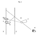
- FIG. 2 relates to a modified embodiment of the device according to FIG. 1 with improved image representation.
- the embodiment according to FIG. 2 is the same after FIG. 1 , wherein furthermore a second retroreflective material 9 is used.
- the second retroreflective material 9 is arranged on the observer side of the semi-transparent mirror 2 and extends substantially away from the mirror 2.
- the exact positioning and geometric extent of the second retroreflective material 9 are not critical and can be adapted to the requirements of the respective intended use of the device. Essential to the invention is thereby alone, the beam section B, as to FIG. 1 explained encounters the second retroreflective material 9.
- the beam path in the embodiment according to FIG. 2 corresponds to the FIG. 1 , Deviating from this, however, the section B of the beam path for the image representation is not lost.
- the beam portion of the section B strikes the second retroreflective material 9 and is reflected by this in its beam path in the manner already described.
- the section B 'thus formed is not shown for illustrative reasons.
- the beam portion B ' is also mirrored or partially mirrored in the manner already described and forms the portion D' (not shown).
- the sections D and D ' are identical in their geometric position, whereby the beam components of D and D' add up and lead to an improved, in particular amplified, representation of the virtual light source 6.
- FIG. 3 shows an application of the device according to the invention FIG. 1 as a virtual switch. It is understood that the image enhancing properties of a second retroreflective material as in FIG. 2 shown in this embodiment application can be found.
- the device for a virtual switch comprises all the features of the device FIG. 1 , whose description is hereby referred to. Furthermore, the virtual switch to FIG. 3 a sensor 8.
- the selection of the type of the sensor 8 is not substantially limited.
- Essential to the invention in the selection of the sensor is that it is capable of the penetration of an object, such as a finger, a hand or a Pen to recognize in the monitored area, hereinafter referred to for the purpose of description as a fingertip 7.
- Such sensors are known and commercially available.
- it is called only optical sensors which operate in the region of visible or infrared light.
- the sensor 8 can be selected so that the viewing window of its working area is limited. This can be achieved in a simple manner by masks or collimators in front of the sensor.
- Such sensors are also commercially available.
- the working range of the sensor 8 can be adapted in its cross section to the size of the virtual light source 6.
- the working area may be larger, smaller or equal to the size of the virtual light source 6.
- the cross-section of the working area of the sensor 8 is approximately equal to the size of the virtual light source 6, relative to the location at which the viewer perceives the virtual light source 6.
- the orientation of the sensor 8 is indicated by a dashed line.
- the senor 8 is a passive optical sensor which responds to the wavelength of the radiation of the associated real light source 1, wherein the threshold of the sensor is selected or adjusted so that the sensor does not respond to the general background radiation of the same wavelength ,
- This embodiment is particularly suitable for the production of precise and error-free working virtual and thus non-contact switches.
- the finger 7 when the viewer 4 tries to touch the virtual light source 6 and to do so moves his finger 7 to the location of the virtual light source 6, the finger 7 causes an increased return beam signal due to the higher light intensity at the location of the virtual light source 6 Thrown back sensor 8, which exceeds the switching threshold of the sensor 8.
- an arbitrary switching signal can then be triggered by the sensor 8.
- the switching threshold of the sensor can be designed so that only an exact positioning of the Fingertip 7 at the location of the virtual light source sufficient reflection generated to allow the sensor to respond, while only partial "touch" of the virtual light source 6 and thus associated with only a lower reflection below the switching threshold. In particular, by the latter measure, a high resistance of the virtual switch against false positive tripping can be ensured.
- a return signal to the operator of the virtual switch can be given via the virtual light source 6.
- this can be done by changing the color of the light of the virtual light source 6, for example, from white light to red light. So-called multi-colored LEDs are particularly suitable for this purpose.
- more complex circuit elements can also be created as virtual switches. For example, sliding or rotary control.
- the movement of the finger 7 is tracked by means of at least two sensors 8 via the virtual representation and implemented accordingly.
- the virtual switch according to the present invention is suitable for all applications in which contactless operation of devices is desired. This may be for aesthetic reasons, or to improve the vandalism safety of public devices, as well as to prevent transmission of germs to health equipment.
- FIGS. 4 and 4a explain the respectively necessary positioning of the viewer 4 to allow him to recognize the virtual light source 6, in particular depending on the configuration of the shield 5.
- a direct visual contact between the viewer 4 and the real light source 1 should be avoided.
- the virtual light source 6 can otherwise be overshadowed by the real light source 1, which impairs the perception of the virtual light source 6 by the viewer 4 or, in the worst case, makes it impossible. This is caused by the fact that the virtual light source 6 due to the nature of your generation always has a lower intensity or luminous intensity than the real source of light generating them 1.
- the direct visual contact is suppressed by a shield 5.
- the term shading is used for the latter and the resulting space in which no direct visual contact is possible, referred to as the shadow area S.
- the shadow area S and the forbidden area P to be explained are shown aborted.
- the areas S and P extend beyond the sheet boundary, which is indicated by the dash-dot line. From the direct comparison of the FIGS. 4 and 4a can be seen how the shadow area S increases or decreases in the same direction with the extension of the shield 5.
- the forbidden area P is shown.
- a viewer 4 in the forbidden area P can not perceive the virtual light source 6, irrespective of the already explained problem of overexposure.
- the extent of the forbidden area P is, like the shadow area S, dependent on the geometric shape of the shield 5. As a result, the size and extent of the forbidden area P can easily be predetermined or adjusted by a person skilled in the art.
- the projection of the shield 5 is drawn at the virtual light source 6 dash-dot-like and for the purposes of the description referred to as pseudo-shield 11.
- the pseudo-shield 11 is not perceived by the viewer 4 and serves in the sense of the description exclusively for the expert to give a means to the hand to predict the prohibited area.
- the pseudo-shield 11 is identical in its position and extension relative to the virtual light source 6 as the shield 5 to the real light source 1, but mirror-inverted. From the backprojection of the boundaries of the pseudo-shield 11 through the virtual light source 6, the limits of the forbidden area P result.
- the forbidden beam path V would be a beam path as it would be necessary for a viewer 4 who is in the forbidden area P stops, the virtual light source to recognize. As can be seen from the figures, the forbidden beam path V would have to pass through the shield 5 for this purpose. The latter is not possible and is therefore referred to as prohibited within the meaning of this description.
- the optimal position of the observer 4 in the shadow area S is. As far as an overlap of the shadow area S and the forbidden area P occurs, the position of the observer may not be in the overlap area.
Description
Die vorliegende Erfindung betrifft eine Vorrichtung zur virtuellen Darstellung einer Lichtquelle, wie beispielsweise einem einzelnen Lichtpunkt, einer Abbildung oder einer Laufschrift, sowie Verwendungen der virtuellen Darstellung der Lichtquelle, beispielsweise in Form eines virtuellen Schalters.The present invention relates to an apparatus for virtual representation of a light source, such as a single light spot, an image or a marquee, and uses the virtual representation of the light source, for example in the form of a virtual switch.
Es hat in der Vergangenheit nicht an Versuchen gefehlt Vorrichtungen für die virtuelle Darstellung eine Lichtquelle bereitzustellen. Im Sinne der vorliegenden Beschreibung wird dabei unter virtueller Darstellung ein virtuelles Bild eines Licht reflektierenden oder leuchtenden Objektes verstanden, dass frei in den Raum projiziert wird, im Gegensatz zu einem reellen Bild, welches auf einer Oberfläche abgebildet wird. So ist aus der
Die
Die
Aufgabe der Vorliegenden Erfindung ist es Vorrichtung und Verfahren für die virtuelle Darstellung einer Lichtquelle oder eines Bildes bereitzustellen, die die Nachteile des Standes der Technik überwinden. Weitere Teilaufgabe war es eine Vorrichtung der genannten Art bereitzustellen, die eine geringe Bautiefe aufweist und kostengünstig herzustellen ist. Weitere Teilaufgabe war es eine Vorrichtung der genannten Art bereitzustellen, bei der die Projektionstiefe der virtuellen Darstellung mit einfachen Mitteln frei eingestellt werden kann. Ebenfalls war es Teilaufgabe der vorliegenden Erfindung einen virtuellen Schalter bereitzustellen.The object of the present invention is to provide a device and method for the virtual representation of a light source or an image, which overcomes the disadvantages of the prior art. Another sub-task was to provide a device of the type mentioned, which has a small overall depth and is inexpensive to manufacture. Another sub-task was to provide a device of the type mentioned, in which the projection depth of the virtual display can be set freely by simple means. It was likewise a partial task of the present invention to provide a virtual switch.
Gelöst werden die Aufgaben mit den technischen Merkmalen des unabhängigen Anspruches. Bevorzugte Ausführungsformen sind in den abhängigen Ansprüchen dargestellt.The objects are achieved with the technical features of the independent claim. Preferred embodiments are presented in the dependent claims.
Die erfindungsgemäße Vorrichtung zur Darstellung einer virtuellen Lichtquelle umfasst in ihrer einfachsten Ausführungsform wenigstens eine reale Lichtquelle, eine Abschirmung der realen Lichtquelle gegen direkte Sicht durch den Betrachter, einen semi-transparenten Spiegel sowie wenigstens einen undurchlässiger Retroreflektor. Erfindungswesentlich ist, dass der semi-transparente Spiegel im wesentlichen parallel zu dem Retroreflektor angeordnet ist. Die reale Lichtquelle ist dabei zwischen den Ebenen des Retroreflektors und des semi-transparenten Spiegels angeordnet.In its simplest embodiment, the device according to the invention for displaying a virtual light source comprises at least one real light source, a shielding of the real light source against direct view by the viewer, a semi-transparent mirror and at least one impermeable retroreflector. Essential to the invention is that the semi-transparent mirror is arranged substantially parallel to the retroreflector. The real light source is arranged between the planes of the retroreflector and the semi-transparent mirror.
Im Sinne der vorliegenden Beschreibung bedeutet reale Lichtquelle, jede Lichtquelle die divergentes Licht abgibt. Dies umfasst, in nicht abschließender Aufzählung, Punktlichtquellen, wie Glühfadenbirnen oder LEDs, längserstreckte Lichtquellen, wie Entladungsröhren oder ähnliches sowie Kombinationen hieraus. Eine reale Lichtquelle mit divergentem Licht kann auch durch eine Laserlichtquelle gebildet werden, welche mit optischen Zusatzeinrichtungen wie beispielsweise Linsen versehen sind, um das parallele Laserlicht in eine divergente Lichtquelle umzuwandeln.As used herein, a real light source means any light source that emits divergent light. This includes, but is not limited to, point light sources such as filament bulbs or LEDs, elongate light sources such as discharge tubes or the like, and combinations thereof. A real light source with divergent light may also be formed by a laser light source provided with optional optical devices such as lenses to convert the parallel laser light into a divergent light source.
Soweit im Zusammenhang mit dieser Beschreibung der Begriff von dem Ort oder Standort des Betrachters verwendet wird, so versteht es sich, dass hiermit der Ort oder Standort seiner visuellen Sinnesorgane gemeint ist.As far as in connection with this description, the term of the location or location of the viewer is used, it is understood that this means the location or location of his visual sense organs.
Retroreflektoren unterschiedlichen Typs sind bekannt und im Handel erhältlich. Bekannte Hersteller sind die Firmen 3M und Reflexite. Grundsätzlich sind alle Retroreflektoren für die Erfindung geeignet. Im Rahmen der Erfindung können die unterschiedlichen Eigenschaften der jeweiligen Typen von Retroreflektoren genutzt werden. So können Retroreflektoren des Prismatypes in der vorliegenden Erfindung Verwendung finden, wenn einen Funkel- oder Sterncheneffekt bei der Darstellung der virtuellen Lichtquelle gewünscht ist. Es zeigte sich, dass zur Erlangung einer Rundform oder Kugelform der virtuellen Lichtquelle die Verwendung von Retroreflektoren des Kugel- oder Linsentyps besonders geeignet sind.Retroreflectors of various types are known and commercially available. Well-known manufacturers are the companies 3M and Reflexite. In principle, all retroreflectors are suitable for the invention. In the context of the invention, the different properties of the respective types of retroreflectors can be used. Thus, retroreflectors of the prism type can be used in the present invention if a sparkling or asterisk effect is desired in the representation of the virtual light source. It has been found that the use of retroreflectors of the spherical or lens type is particularly suitable for obtaining a round shape or spherical shape of the virtual light source.
Eine wesentliche Komponente der erfindungsgemäßen Vorrichtung ist der Abschirmung der realen Lichtquelle gegen direkte Sicht durch den Betrachter. An das Material der Abschirmung selbst sind keine wesentlichen Anforderungen gestellt, als das es die direkte Sicht unterbindet. Die Abschirmung ist in unmittelbarer Nähe der realen Lichtquelle angeordnet. Aus Letzterem ergibt sich der Vorteil, das konstruktiv die Befestigung der Abschirmung an der Lichtquelle oder dem Lichtquellenträger, erfolgen kann, was konstruktiv einfacher ist als die freie Positionierung der Abschirmung im Raum vor der realen Lichtquelle. Auf die Funktion der erfindungsgemäßen Vorrichtung hat dies jedoch keinen Einfluss. Auch ist es möglich, die Abschirmung als integralen Bestandteil der realen Lichtquelle auszuführen. Beispielsweise durch teilweises Aufbringen einer lichtundurchlässigen Beschichtung auf den Leuchtkörper. Aus Kostengründen ist es jedoch Bevorzugt die Abschirmung als eigenständige Baugruppe auszuführen. Letzteres ermöglicht die Verwendung von handelüblichen Leuchtkörpern als reale Lichtquelle, ohne das diese einem besonderen Modifikationsschritt unterzogen werden müssen.An essential component of the device according to the invention is the shielding of the real light source against direct view by the viewer. To the material of the shield itself no essential requirements are set, as it prevents the direct view. The shield is arranged in the immediate vicinity of the real light source. From the latter, there is the advantage of being constructive the attachment of the shield to the light source or the light source carrier, can be done, which is structurally simpler than the free positioning of the shield in the space in front of the real light source. However, this does not affect the function of the device according to the invention. It is also possible to carry out the shielding as an integral part of the real light source. For example, by partially applying an opaque coating on the luminous body. For cost reasons, however, it is preferred to carry out the shield as an independent module. The latter makes it possible to use commercially available illuminants as a real light source without having to subject them to a special modification step.
Ein weiteres erfindungswesentliches Merkmal ist, das jeder in der Vorrichtung angeordneten realen Lichtquelle die eine virtuellen Lichtquelle erzeugen soll, eine eigene Abschirmung zugeordnet ist. Hieraus ergibt sich ein weiterer Vorteil. Bei Vorrichtungen mit zwei oder mehrer realen Lichtquellen kann die Ausformung der jeweiligen Abschirmungen und damit ihr unterschiedlicher Abschattungsbereich sowie der verbotene Bereich für alle virtuellen Lichtquellen gleich oder individuell eingestellt werden. Während bei im wesentlichen übereinstimmendem Abschattungsbereich und verbotenen Bereich der Betrachter immer alle virtuellen Lichtquellen wahrnehmen kann, soweit er sich im dem Bereich aufhält in dem die Wahrnehmung möglich ist, so kann bei individueller Ausgestaltung des Schattenbereiches und/oder des verbotenen Bereiches die Vorrichtung so ausgeführt werden, dass der Betrachter von einem Standort aus eine somit vorreingestellte Auswahl an virtuellen Lichtquellen wahrnimmt, während er nach Standortwechsel eine andere vorreingestellte Auswahl an virtuellen Lichtquellen wahrnimmt. Mit anderen Worten kann die Wahrnehmung der jeweiligen virtuellen Lichtquellen für den Betrachter Standortabhängig eingestellt werden, soweit dies für die jeweilige Anwendung gewünscht ist.Another essential feature of the invention is that each arranged in the device real light source is to generate a virtual light source, a separate shield is assigned. This results in another advantage. In devices with two or more real light sources, the shape of the respective shields and thus their different shading area and the forbidden area for all virtual light sources can be set the same or individually. While the viewer can always perceive all the virtual light sources in the substantially coinciding shading area and forbidden area, insofar as it is located in the area in which the perception is possible, the device can thus be designed with individual configuration of the shadow area and / or the forbidden area in that the observer perceives a preselected selection of virtual light sources from one location while perceiving a different preselected selection of virtual light sources after relocation. In other words, the perception of the respective virtual light sources can be adjusted for the observer depending on the location, as far as this is desired for the respective application.
Im Umfange der Erfindung kann die Abschirmung bei einer Punktlichtquelle halbschalenförmig und bei einer längserstreckten realen Lichtquelle rinnenförmig ausgestaltet sein. Dieser Kunstgriff erlaubt es, durch die Auswahl der jeweiligen Erstreckung und Ausdehnung der Abschirmung den Abschattungsbereich einzustellen in welchem der Betrachter sich aufhalten muss, um die virtuelle Lichtquelle erkennen zu können, wobei gleichzeitig die restlichen Baugruppen der Vorrichtung unverändert bleiben. Der Vorteil hieraus liegt auf der Hand. Insbesondere bei der Serienherstellung kann der Abschattungsbereich den individuellen Anwendungsbedürfnissen angepasst werden, indem unterschiedliche Halbschalen, bzw. Rinnen als Abschirmung verbaut werden, wobei die restlichen Baugruppen im Herstellungsvorgang unverändert bleiben.In the scope of the invention, the shield can be configured in the form of a half-shell in the case of a point light source and in the form of a groove in the case of an elongated real light source. This artifice makes it possible, by selecting the extent and extent of the shielding, to set the shadowing area in which the observer must stand to be able to recognize the virtual light source, while at the same time leaving the remaining components of the device unchanged. The advantage of this is obvious. Especially in series production, the shading area can be adapted to individual application needs be installed by different shells, or gutters as a shield, the remaining modules remain unchanged in the manufacturing process.
Der Bereich von dem aus der Betrachter die virtuelle Lichtquelle wahrnehmen kann sowie der Ort an dem die virtuelle Lichtquelle dem Betrachter erscheint unterliegen geometrischen Gesetzmäßigkeiten. Hier liegt ein weiterer Vorteil der vorliegenden Erfindung. Durch Auswahl des Abstandes zwischen dem semi-transparenten Spiegel und dem Retroreflektormaterial in Verbindung mit der Positionierung der realen Lichtquelle hierzwischen, kann die Projektionstiefe der virtuellen Lichtquelle eingestellt werden und somit auf den Ort an dem die virtuelle Lichtquelle dem Betrachter erscheint Einfluss genommen werden. Im einfachsten Fall, wenn die reale Lichtquelle unmittelbar vor dem Retroreflektormaterial angeordnet ist, so beträgt die Projektionstiefe gleich dem Abstand zwischen dem Retroreflektormaterial und dem semi-transparenten Spiegel. Durch einfache Änderung des Abstandes zwischen diesen Baugruppen kann der Fachmann die Projektionstiefe in Abhängigkeit der jeweiligen Anwendung einstellen. Der Bereich von dem der Betrachter die virtuelle Lichtquelle wahrnehmen kann, wird wie beschrieben durch den Abschattungsbereich eingestellt. Zusammen erhält der Fachmann damit eine Vielzahl von Variationsmöglichkeiten, um die Vorrichtung den jeweils gewünschten Anforderungen anzupassen.The area from which the viewer can perceive the virtual light source as well as the place where the virtual light source appears to the viewer are subject to geometric laws. This is another advantage of the present invention. By selecting the distance between the semi-transparent mirror and the retroreflective material in conjunction with the positioning of the real light source therebetween, the projection depth of the virtual light source can be adjusted, thus affecting the location where the virtual light source appears to the viewer. In the simplest case, when the real light source is located immediately in front of the retroreflective material, the projection depth is equal to the distance between the retroreflective material and the semi-transparent mirror. By simply changing the distance between these assemblies, the skilled person can adjust the depth of projection depending on the particular application. The area from which the viewer can perceive the virtual light source is set by the shading area as described. Together, the expert thus receives a variety of possible variations in order to adapt the device to the respective desired requirements.
In Abhängigkeit der jeweiligen Verwendung der erfindungsgemäßen Vorrichtung kann es einen anwendungsbedingten Bereich geben, in dem sich der Betrachter aufhalten soll. Eine typische Anwendung wäre beispielsweise als senkrechte Werbe- oder Anzeigetafel die an einer Wand befestigt ist. Der anwendungsbedingte Standort des Betrachters wäre vor der Tafel und unterhalb der Anzeige. Eine andere typische Anwendung der Vorrichtung, ggf. in der Ausführungsform als virtueller Schalter, wäre ein flach angeordnetes Bedienpaneel. Der anwendungsbedingte Standort des Betrachters vor dem Bedienpaneel und oberhalb davon.Depending on the particular use of the device according to the invention, there may be an application-related area in which the viewer should stay. A typical application would be, for example, as a vertical advertising or scoreboard mounted on a wall. The application-related location of the viewer would be in front of the panel and below the display. Another typical application of the device, possibly in the embodiment as a virtual switch, would be a flat control panel. The application-related location of the viewer in front of the control panel and above it.
Ausgehend von den genannten anwendungsbedingten Standorten des Betrachters kann der Fachmann die erfindungsgemäße Vorrichtung ohne weiteres so aufführen, dass der Betrachter am genannten Standort die virtuelle Lichtquelle wahrnehmen kann. Hierzu genügt es, dass die reale Lichtquelle, der Betrachter und der in Zusammenhang mit
Spezieller Teil der BeschreibungSpecial part of the description
Nachfolgend werden die Erfindung und weitere Ausführungsformen anhand der Figuren erläutert, wobei die Erfindung nicht auf die dargestellten Ausführungsformen beschränkt ist. Dabei zeigen:
-
Figur 1 -
Figur 2Vorrichtung nach Figur 1 in einer Ausführungsform zur verbesserten Bildgebung; -
Figur 3Vorrichtung nach Figur 1 in einer Ausführungsform als virtueller Schalter; -
Figuren 4 und 4a
-
FIG. 1 the device for virtual representation of a light source in its simplest embodiment using a real point light source; -
FIG. 2 the device afterFIG. 1 in an embodiment for improved imaging; -
FIG. 3 the device afterFIG. 1 in one embodiment as a virtual switch; -
FIGS. 4 and 4a The geometric specifications of the real light source, shielding and observer location to be met.
In der dargestellten Ausführungsform ist die reale Lichtquelle 1 mit der Abschirmung 5 in Form eines halbkugelförmigen Sichtschutzes versehen. Die Abschirmung 5 in der dargestellten Form eignet sich insbesondere für Punktlichtquellen. Wie bereits ausgeführt dient die Abschirmung 5 dazu den direkten Sichtkontakt zwischen dem Betrachter 4 und der realen Lichtquelle 1 zu unterbinden. So kann in einer nicht dargestellten Ausführungsform die Abschirmung direkt auf den Leuchtkörper der realen Lichtquelle aufgebracht werden. Auch ist es möglich die Abschirmung als planes oder nahezu planes Element auszuführen, das zwischen dem Retroreflektormaterial 3 und dem semi-transparenten Spiegel 2 angeordnet ist. Auch ist es möglich die Abschirmung in den semi-transparenten Spiegel 2 zu integrieren, bzw. einen Teil des semi-transparenten Spiegels als Abschirmung auszuführen. Wesentlich ist dabei die geometrische Anordnung von realer Lichtquelle 1, Abschirmung 5, Betrachter 4 und sich daraus ergebend der Ort der virtuellen Darstellung, bzw. virtuellen Lichtquelle 6. Letzteres wird im Folgenden noch erläutert, wodurch der Fachmann in die Lage versetzt wird die genannten Ausführungsformen mit abgewandelter Abschirmung ohne weiteres im Rahmen der vorliegenden Erfindung auszuführen.In the illustrated embodiment, the real
Die Funktionsweise der Vorrichtung wird beispielhaft an einen Strahlengang erläutert. Aus zeichnerischen Gründen sind die Vielzahl der weiteren Strahlengänge, die die divergente reale Lichtquelle 1 verlassen, nicht dargestellt. Ausgehend von der realen Lichtquelle 1 verläuft der exemplarische Strahlengang in Richtung auf den semi-transparenten Spiegel 2. Dieser Abschnitt des Strahlenganges ist mit dem Buchstaben A bezeichnet. Am semi-transparenten Spiegel 2 wird der Strahlengang am Punkt K in die Teile B und C geteilt. Der Teil des Strahlenganges B tritt durch den Spiegel hindurch (in
Der Strahlenteil des Abschnittes C trifft auf das Retroreflektormaterial 3 und wird von diesem als Abschnitt C' in sich gespiegelt und auf den Punkt K zurückgeworfen. Der Abschnitt C' ist aus zeichnerischen Gründen nicht dargestellt. Am Punkt K wird der Strahl des Abschnittes C' wieder entsprechend der obigen Ausführungen geteilt, nämlich in die Abschnitte A' (ebenfalls aus zeichnerischen Gründen nicht dargestellt) welcher in die Lichtquelle 1 zurückgeworfen wird und den Abschnitt D welcher zur Darstellung der virtuellen Darstellung, bzw. Lichtquelle 6 dient, die vom Betrachter 4 erkannt wird.The beam portion of the section C strikes the
Es zeigte sich, das die Projektionstiefe der virtuellen Lichtquelle 6, das heißt der Abstand zwischen der erfindungsgemäßen Vorrichtung und dem Ort an dem der Betrachter die virtuelle Lichtquelle wahrnimmt, im wesentlichen durch den Abstand des Retroreflektormaterials 3 und dem semi-transparenten Spiegel 2 eingestellt wird. Bei Anordnung der realen Lichtquelle in unmittelbarer Nähe des Retroreflektormaterials 3 ist die Projektionstiefe etwa gleich dem Abstand zwischen dem Retroreflektormaterial 3 und dem semi-transparenten Spiegel 2. Die Vorteile hieraus liegen auf der Hand.It was found that the projection depth of the virtual
Da der Abstand zwischen den zuletzt genannten Baugruppen nahezu frei eingestellt werden kann, so kann in Abhängigkeit davon die Projektionstiefe für die virtuelle Lichtquelle 6 ebenfalls frei eingestellt werden. Durch diesen Kunstgriff kann, soweit vom Anwender gewünscht, die virtuelle Lichtquelle 6 so eingestellt werden, dass sie vom Betrachter in unmittelbarer Nähe zur erfindungsgemäßen Vorrichtung wahrgenommen wird. Umgekehrt kann durch eine geringfügige Abwandlung der erfindungsgemäßen Vorrichtung, nämlich der Vergrößerung des Abstandes zwischen dem Retroreflektormaterial 3 und dem semi-transparenten Spiegel 2, die virtuelle Lichtquelle 6 so eingestellt werden, dass sie vom Betrachter in größerem Abstand zur erfindungsgemäßen Vorrichtung wahrgenommen wird.Since the distance between the last-mentioned assemblies can be set almost freely, so depending on the projection depth for the virtual
Gemäß einer nicht dargestellten Ausführungsform kann es zweckmäßig sein, die dem Betrachter 4 zugewandte Seite der Abschirmung 5 ebenfalls mit einem Retroreflektormaterial zu versehen. Dies gilt insbesondere soweit die Vorrichtung mit 2 oder mehr realen Lichtquellen 1 ausgestattet ist, welche eigenständige Abschirmungen 5 aufweisen, die in unmittelbare Nähe der zugeordneten realen Lichtquelle 1 angeordnet sind. Bei einer solchen Ausführungsform kann es unter ungünstigen Umständen zur Ausbildung von blinden Flecken kommen, in denen der Betrachter 4 eine virtuelle Lichtquelle nicht wahrnehmen kann, obwohl die grundsätzlichen geometrischen Bedingungen für die Wahrnehmung der virtuellen Lichtquelle erfüllt sind. Zur Ausbildung eines solchen blinden Fleckes kann es kommen, wenn der Strahlengangabschnitt C einer realen Lichtquelle 1 auf die dem Betrachter 4. zugewandten Seite der Abschirmung 5 einer zweiten realen Lichtquelle geworfen wird. Soweit die Abschirmung 5 der zweiten realen Lichtquelle nicht mit einem Retroreflektor versehen ist, kommt es zum Verlust des Strahlenganges welcher dann nicht mehr zur Bildung der virtuellen Lichtquelle 6 zur Verfügung steht. Hieraus ergibt sich auch, das Größe und Ausdehnung eines genannten blinden Fleckes unmittelbar mit Größe und Ausdehnung der jeweiligen Abschirmung 5 korrelieren. Durch die Maßnahme, die dem Betrachter 4 zugewandte Seite der Abschirmungen 5 mit einem Retroreflektormaterial zu versehen, kann die Bildung der genannten blinden Flecke wirkungsvoll vermieden werden. Es versteht sich, das die genannte Maßnahme nicht nur auf Abschirmungen 5 beschränkt ist die in unmittelbarer Nähe der realen Lichtquelle 1 angeordnet sind, sonder auf alle Abschirmungen angewandt werden kann, die zwischen dem Retroreflektormaterial 3 und dem semi-transparenten Spiegel 2 angeordnet sind.According to an embodiment, not shown, it may be appropriate to provide the
Der Strahlengang in der Ausführungsform nach
Die Auswahl des Typs des Sensors 8 unterliegt keinen wesentlichen Beschränkungen. Erfindungswesentlich bei der Auswahl des Sensors ist, dass dieser in der Lage ist das Eindringen eines Objektes, wie beispielsweise eines Fingers, einer Hand oder eines Stiftes, in den zu überwachenden Bereich zu erkennen, nachfolgend zum Zwecke der Beschreibung als Fingerkuppe 7 bezeichnet. Derartige Sensoren sind bekannt und im Handel erhältlich. Beispielhaft seinen nur optische Sensoren genannt, die im Bereich des sichtbaren oder infraroten Lichtes arbeiten. Geeignetenweise kann der Sensor 8 so ausgewählt werden, dass das Sichtfenster seines Arbeitsbereiches beschränkt ist. Dies kann in einfacher Weise durch Masken oder Kollimatoren vor dem Sensor erreicht werden. Auch derartige Sensoren sind im Handel erhältlich.The selection of the type of the
Insbesondere bei einer Punktlichtquelle als reale Lichtquelle 1, kann der Arbeitsbereich des Sensors 8 in seinem Querschnitt an die Größe der virtuellen Lichtquelle 6 angepasst werden. In Abhängigkeit der jeweilige Anwendung kann der Arbeitsbereich größer, kleiner oder gleich der Größe der virtuellen Lichtquelle 6 sein.Particularly in the case of a point light source as a real
In der Ausführungsform nach
In einer bevorzugten Ausführungsform ist der Sensor 8 ein passiver optischer Sensor, der auf die Wellenlänge der Strahlung der ihm zugeordneten realen Lichtquelle 1 reagiert, wobei die Ansprechschwelle des Sensors so gewählt oder eingestellt ist, dass der Sensor auf die allgemeine Hintergrundstrahlung der gleichen Wellenlänge nicht anspricht. Diese Ausführungsform ist besonders für die Herstellung von präzise und fehlerfrei arbeitenden virtuellen und damit berührungslos tätigen Schaltern geeignet.In a preferred embodiment, the
Wenn in dieser Ausführungsform der Betrachter 4 versucht die virtuelle Lichtquelle 6 zu berühren und dazu seinen Finger 7 an den Ort der virtuellen Lichtquelle 6 bewegt, so wird, aufgrund der höheren Lichtintensität am Ort der virtuellen Lichtquelle 6, von dem Finger 7 ein erhöhtes Rückstrahlsignal an Sensor 8 zurückgeworfen, welches die Schaltschwelle des Sensors 8 übersteigt. In bekannter Weise kann dann durch den Sensor 8 ein beliebiges Schaltsignal ausgelöst werden. Die Schaltschwelle des Sensors kann so ausgelegt werden, dass nur ein exaktes Positionieren der Fingerkuppe 7 am Ort der virtuellen Lichtquelle hinreichend Rückstrahlung erzeugt, um den Sensor ansprechen zu lassen, während nur teilweises "berühren" der virtuellen Lichtquelle 6 und damit verbunden nur einer geringeren Rückstrahlung unterhalb der Schaltschwelle liegt. Insbesondere durch letztere Maßnahme kann eine hohe Resistenz des virtuellen Schalters gegen falsch-positives-Auslösen sichergestellt werden.In this embodiment, when the
Soweit für die jeweilige Anwendung gewünscht, so kann über die virtuelle Lichtquelle 6 ein Rücksignal an den Bediener des virtuellen Schalters gegeben werden. In der einfachsten Weise kann dies durch den Wechsel der Farbe des Lichtes der virtuellen Lichtquelle 6, beispielsweise von weißem Licht auf rotes Licht, geschehen. Sogenannte mehrfarbige LEDs sind hierfür besonders geeignet.If desired for the particular application, a return signal to the operator of the virtual switch can be given via the virtual
Durch Zusammenwirken mehrerer virtueller Schalter ist möglich eine Schaltmatrix für die Bedienung komplexerer Geräte zusammenzustellen.Through interaction of several virtual switches it is possible to put together a switching matrix for the operation of more complex devices.
Durch Zusammenwirken mehrer Sensoren 8 mit entweder mehreren realen Punktlichtquellen oder einer oder mehrer realen längserstreckten Lichtquellen sowie Kombinationen hieraus, können auch komplexere Schaltungselemente als virtuelle Schalter erzeugt werden. Beispielsweise Schiebe- oder Drehregler. Dabei wird die Bewegung des Fingers 7 mittels wenigstens zweier Sensoren 8 über die virtuelle Darstellung verfolgt und entsprechend umgesetzt.By interacting with a plurality of
Der virtuelle Schalter gemäß der vorliegenden Erfindung ist für alle Anwendungen geeignet, in denen eine berührungslose Bedienung von Geräten gewünscht ist. Dies kann aus ästhetischen Gründen sein oder auch zur Verbesserung der Vandalismussicherheit bei Geräten im öffentlichen Bereich sowie zu Verhinderung der Übertragung von Keimen bei Geräten im Gesundheitsbereich.The virtual switch according to the present invention is suitable for all applications in which contactless operation of devices is desired. This may be for aesthetic reasons, or to improve the vandalism safety of public devices, as well as to prevent transmission of germs to health equipment.
Die
Wie ebenfalls schon erläutert, wird der direkte Sichtkontakt durch eine Abschirmung 5 unterbunden. Zum Zwecke der Beschreibung wird für letzteres der Begriff Abschattung verwendet und der daraus resultierende Raum in dem kein direkter Sichtkontakt möglich ist, als Schattenbereich S bezeichnet. In den zeichnerischen Darstellungen nach
Weiterhin ist in den
Zum besseren Verständnis des verbotenen Bereiches P ist in den
Die Pseudoabschirmung 11 ist relativ zur virtuellen Lichtquelle 6 in ihrer Lage und Erstreckung identisch wie die Abschirmung 5 zur realen Lichtquelle 1, jedoch spiegelverkehrt. Aus der Rückprojektion der Grenzen der Pseudoabschirmung 11 durch die virtuelle Lichtquelle 6 ergeben sich die Grenzen des verbotenen Bereiches P. Zum besseren Verständnis des verbotenen Bereiches P ist in den
Zusammengefasst ergibt sich, das die optimale Position des Betrachters 4 im Schattenbereich S ist. Soweit es zu einer Überschneidung des Schattenbereiches S und dem Verbotenen Bereich P kommt, so darf sich die Position des Betrachter nicht im dem Überschneidungsbereich befinden.In summary, it follows that the optimal position of the
Claims (9)
- A device for generating a virtual light source, comprising at least one real light source (1), a retroreflector material (3) and a semitransparent mirror (2), characterised in that the device further comprises one shield (5), respectively, for shielding the real light source (1) from direct view by an observer (4) for each of the real light sources (1) and the shield (5) is disposed in the immediate vicinity of the respective real light source (1), wherein, furthermore, the retroreflector material (3) and the semitransparent mirror (2) are disposed substantially parallel to each other and the at least one real light source (1) is disposed between planes of the retroreflector material (3) and of the semitransparent mirror (2).
- The device according to claim 1, characterised in that the device comprises a second retroreflector material (9), wherein the second retroreflector material (9) is disposed on the side of the observer of the semitransparent mirror (2) and substantially extends away from the device.
- The device according to claim 1 or 2, characterised in that the shield (5) is provided with a retroreflector material, in each case on the side of the observer.
- The device according to any one of the preceding claims, characterised in that the device comprises at least two real light sources (1) and the respective shields (5) are formed differently for forming different shading regions (S) and/or prohibited regions (P).
- The device according to any one of the preceding claims, characterised in that the device comprises at least one sensor (8), the window of the sensor (8) facing towards a virtual light source (6) assigned to it.
- The device according to claim 5, characterised in that the sensor (8) is a passive optical sensor that reacts to the wavelength of the radiation of the real light source (1) assigned to it.
- The device according to claim 5 or 6, characterised in that the switching threshold of the sensor (8) is set in such a manner than the sensor (8) reacts only to an intensity of a returning radiation that is generated by a complete introduction of an object (7) into the virtual light source (6).
- The device according to any one of the claims 5 to 7, characterised in that a reaction of the sensor (8) is signalled by a change of colour of the light of the real light source (1).
- The device according to any one of the claims 5 to 8, characterised in that the device comprises at least one longitudinally extended or two point-shaped light sources (6) with at least two assigned sensors (8), the sensors (8) forming a switch matrix.
Applications Claiming Priority (2)
| Application Number | Priority Date | Filing Date | Title |
|---|---|---|---|
| DE102008022011A DE102008022011A1 (en) | 2008-05-02 | 2008-05-02 | Device for virtual representation of a light source and use of this |
| PCT/DE2009/000587 WO2009132629A1 (en) | 2008-05-02 | 2009-04-28 | Device for the virtual representation of a light source and use of same |
Publications (2)
| Publication Number | Publication Date |
|---|---|
| EP2274646A1 EP2274646A1 (en) | 2011-01-19 |
| EP2274646B1 true EP2274646B1 (en) | 2014-06-25 |
Family
ID=41057772
Family Applications (1)
| Application Number | Title | Priority Date | Filing Date |
|---|---|---|---|
| EP09737737.8A Not-in-force EP2274646B1 (en) | 2008-05-02 | 2009-04-28 | Device for the virtual representation of a light source and use of same |
Country Status (3)
| Country | Link |
|---|---|
| EP (1) | EP2274646B1 (en) |
| DE (1) | DE102008022011A1 (en) |
| WO (1) | WO2009132629A1 (en) |
Families Citing this family (2)
| Publication number | Priority date | Publication date | Assignee | Title |
|---|---|---|---|---|
| CN102322839B (en) * | 2011-06-15 | 2013-05-22 | 上海理工大学 | Device and method for measuring light emergent angle of optical virtual light source |
| DE102012105170B3 (en) * | 2012-06-14 | 2013-09-26 | Martin Göbel | Device for generating a virtual light image |
Family Cites Families (14)
| Publication number | Priority date | Publication date | Assignee | Title |
|---|---|---|---|---|
| DE1853000U (en) * | 1962-03-26 | 1962-06-07 | Reichert Optische Werke Ag | LIGHTING DEVICE FOR MICROSCOPES. |
| US3522980A (en) * | 1969-01-21 | 1970-08-04 | Joe J Lones | Optical sighting system |
| US3787109A (en) * | 1972-06-28 | 1974-01-22 | Honeywell Inc | Inside helmet sight apparatus |
| EP0065954A1 (en) | 1980-08-29 | 1982-12-08 | KASSIES, Michiel | Real image projection device |
| GB9012667D0 (en) | 1990-06-07 | 1990-08-01 | Emi Plc Thorn | Apparatus for displaying an image |
| US5121099A (en) * | 1990-08-31 | 1992-06-09 | Hughes Aircraft Company | Two-page automotive virtual image display |
| GB2284680A (en) * | 1993-12-13 | 1995-06-14 | Central Research Lab Ltd | Apparatus for displaying a suspended image |
| DE19521961A1 (en) * | 1995-06-16 | 1996-12-19 | Jurca Optoelektronik Gmbh | Method and device for determining the distance between a base and a reflecting surface by means of radiation reflected on the surface |
| JP3525367B2 (en) * | 1995-10-24 | 2004-05-10 | 株式会社タイテック | Touchless switch |
| JP2001506772A (en) * | 1996-12-20 | 2001-05-22 | シーメンス アクチエンゲゼルシヤフト | Information display system for at least one person |
| US6027216A (en) * | 1997-10-21 | 2000-02-22 | The Johns University School Of Medicine | Eye fixation monitor and tracker |
| GB2336220B (en) | 1998-04-09 | 2001-11-14 | Central Research Lab Ltd | Apparatus for displaying an image suspended in space |
| FR2790575B3 (en) * | 1999-03-05 | 2001-10-12 | Maurice Bocquet | DEVICE FOR ALLOWING THE IMMATAL SPLASHING OF VIDEO IMAGES INTO A VACUUM |
| US6487809B1 (en) * | 2001-12-19 | 2002-12-03 | American Technologies Network Corporation | Optical sight system with wide range of shooting distances |
-
2008
- 2008-05-02 DE DE102008022011A patent/DE102008022011A1/en not_active Ceased
-
2009
- 2009-04-28 EP EP09737737.8A patent/EP2274646B1/en not_active Not-in-force
- 2009-04-28 WO PCT/DE2009/000587 patent/WO2009132629A1/en active Application Filing
Also Published As
| Publication number | Publication date |
|---|---|
| EP2274646A1 (en) | 2011-01-19 |
| DE102008022011A1 (en) | 2009-11-05 |
| WO2009132629A1 (en) | 2009-11-05 |
Similar Documents
| Publication | Publication Date | Title |
|---|---|---|
| DE102012105170B3 (en) | Device for generating a virtual light image | |
| DE102015101424B4 (en) | lighting device | |
| EP2750914B1 (en) | Method and device for making available a user interface, in particular in a vehicle | |
| DE102013114369B4 (en) | CAMERA MODULE FOR A VEHICLE AND SUBSEQUENT MONITORING SYSTEM | |
| DE102012103684A1 (en) | Display device i.e. projector, for use in oven, has optic causing deflection for light beams, and comprising light guide elements that influence projection of projection image into review region formed in window | |
| DE102012112268A1 (en) | Buttons with dynamically projected symbols | |
| WO2016041683A1 (en) | Display and operating device, especially for a motor vehicle, operating element, and motor vehicle | |
| DE102016115258A1 (en) | Seamless instrument cluster | |
| EP3549824B1 (en) | Lighting device for illuminating the interior of a vehicle | |
| EP2274646B1 (en) | Device for the virtual representation of a light source and use of same | |
| DE102015011412B4 (en) | Method for producing a component with illuminated symbols for an operating device of a motor vehicle | |
| EP2943377B1 (en) | Illumination for the detection of raindrops on a window by means of a camera | |
| EP1626318A1 (en) | Apparatus and method for preventing collision | |
| EP1574880B2 (en) | Emitter for light barrier, light curtain or similar | |
| EP3622341B1 (en) | Motor vehicle display device and motor vehicle | |
| DE102014106680B4 (en) | Switch operating device, mobile device and method for operating a switch by a non-tactile "push" gesture | |
| DE102015013054A1 (en) | Variable arrangement of functions on a sensory control panel | |
| AT514292A1 (en) | Stop device for a bending machine | |
| EP2790040B1 (en) | System and method for configuring a surveillance area of an optoelectronic monitoring device | |
| DE102017004030B4 (en) | Method and device for securing a work space | |
| DE102014115471A1 (en) | Head-mounted display device | |
| EP2034352A2 (en) | Laser projection system with power monitoring | |
| DE102021120552A1 (en) | Motor vehicle with a lighting device and a camera for gesture control | |
| DE102005011355A1 (en) | Opto-electronic unit e.g. LED, for e.g. sensor, has cap made of material transparent for radiation and including optical absorbing layer that partially absorbs radiation such that radiation is suppressed in defined solid angle area | |
| DE112020005825T5 (en) | INDICATOR |
Legal Events
| Date | Code | Title | Description |
|---|---|---|---|
| PUAI | Public reference made under article 153(3) epc to a published international application that has entered the european phase |
Free format text: ORIGINAL CODE: 0009012 |
|
| 17P | Request for examination filed |
Effective date: 20101129 |
|
| AK | Designated contracting states |
Kind code of ref document: A1 Designated state(s): AT BE BG CH CY CZ DE DK EE ES FI FR GB GR HR HU IE IS IT LI LT LU LV MC MK MT NL NO PL PT RO SE SI SK TR |
|
| AX | Request for extension of the european patent |
Extension state: AL BA RS |
|
| DAX | Request for extension of the european patent (deleted) | ||
| GRAP | Despatch of communication of intention to grant a patent |
Free format text: ORIGINAL CODE: EPIDOSNIGR1 |
|
| INTG | Intention to grant announced |
Effective date: 20140314 |
|
| GRAS | Grant fee paid |
Free format text: ORIGINAL CODE: EPIDOSNIGR3 |
|
| GRAA | (expected) grant |
Free format text: ORIGINAL CODE: 0009210 |
|
| AK | Designated contracting states |
Kind code of ref document: B1 Designated state(s): AT BE BG CH CY CZ DE DK EE ES FI FR GB GR HR HU IE IS IT LI LT LU LV MC MK MT NL NO PL PT RO SE SI SK TR |
|
| REG | Reference to a national code |
Ref country code: GB Ref legal event code: FG4D Free format text: NOT ENGLISH |
|
| REG | Reference to a national code |
Ref country code: CH Ref legal event code: EP |
|
| REG | Reference to a national code |
Ref country code: AT Ref legal event code: REF Ref document number: 675026 Country of ref document: AT Kind code of ref document: T Effective date: 20140715 |
|
| REG | Reference to a national code |
Ref country code: IE Ref legal event code: FG4D Free format text: LANGUAGE OF EP DOCUMENT: GERMAN |
|
| REG | Reference to a national code |
Ref country code: DE Ref legal event code: R096 Ref document number: 502009009572 Country of ref document: DE Effective date: 20140814 |
|
| REG | Reference to a national code |
Ref country code: NL Ref legal event code: T3 |
|
| PG25 | Lapsed in a contracting state [announced via postgrant information from national office to epo] |
Ref country code: FI Free format text: LAPSE BECAUSE OF FAILURE TO SUBMIT A TRANSLATION OF THE DESCRIPTION OR TO PAY THE FEE WITHIN THE PRESCRIBED TIME-LIMIT Effective date: 20140625 Ref country code: NO Free format text: LAPSE BECAUSE OF FAILURE TO SUBMIT A TRANSLATION OF THE DESCRIPTION OR TO PAY THE FEE WITHIN THE PRESCRIBED TIME-LIMIT Effective date: 20140925 Ref country code: LT Free format text: LAPSE BECAUSE OF FAILURE TO SUBMIT A TRANSLATION OF THE DESCRIPTION OR TO PAY THE FEE WITHIN THE PRESCRIBED TIME-LIMIT Effective date: 20140625 Ref country code: CY Free format text: LAPSE BECAUSE OF FAILURE TO SUBMIT A TRANSLATION OF THE DESCRIPTION OR TO PAY THE FEE WITHIN THE PRESCRIBED TIME-LIMIT Effective date: 20140625 Ref country code: GR Free format text: LAPSE BECAUSE OF FAILURE TO SUBMIT A TRANSLATION OF THE DESCRIPTION OR TO PAY THE FEE WITHIN THE PRESCRIBED TIME-LIMIT Effective date: 20140926 |
|
| REG | Reference to a national code |
Ref country code: LT Ref legal event code: MG4D |
|
| PG25 | Lapsed in a contracting state [announced via postgrant information from national office to epo] |
Ref country code: LV Free format text: LAPSE BECAUSE OF FAILURE TO SUBMIT A TRANSLATION OF THE DESCRIPTION OR TO PAY THE FEE WITHIN THE PRESCRIBED TIME-LIMIT Effective date: 20140625 Ref country code: HR Free format text: LAPSE BECAUSE OF FAILURE TO SUBMIT A TRANSLATION OF THE DESCRIPTION OR TO PAY THE FEE WITHIN THE PRESCRIBED TIME-LIMIT Effective date: 20140625 Ref country code: SE Free format text: LAPSE BECAUSE OF FAILURE TO SUBMIT A TRANSLATION OF THE DESCRIPTION OR TO PAY THE FEE WITHIN THE PRESCRIBED TIME-LIMIT Effective date: 20140625 |
|
| PG25 | Lapsed in a contracting state [announced via postgrant information from national office to epo] |
Ref country code: CZ Free format text: LAPSE BECAUSE OF FAILURE TO SUBMIT A TRANSLATION OF THE DESCRIPTION OR TO PAY THE FEE WITHIN THE PRESCRIBED TIME-LIMIT Effective date: 20140625 Ref country code: ES Free format text: LAPSE BECAUSE OF FAILURE TO SUBMIT A TRANSLATION OF THE DESCRIPTION OR TO PAY THE FEE WITHIN THE PRESCRIBED TIME-LIMIT Effective date: 20140625 Ref country code: EE Free format text: LAPSE BECAUSE OF FAILURE TO SUBMIT A TRANSLATION OF THE DESCRIPTION OR TO PAY THE FEE WITHIN THE PRESCRIBED TIME-LIMIT Effective date: 20140625 Ref country code: RO Free format text: LAPSE BECAUSE OF FAILURE TO SUBMIT A TRANSLATION OF THE DESCRIPTION OR TO PAY THE FEE WITHIN THE PRESCRIBED TIME-LIMIT Effective date: 20140625 Ref country code: SK Free format text: LAPSE BECAUSE OF FAILURE TO SUBMIT A TRANSLATION OF THE DESCRIPTION OR TO PAY THE FEE WITHIN THE PRESCRIBED TIME-LIMIT Effective date: 20140625 Ref country code: PT Free format text: LAPSE BECAUSE OF FAILURE TO SUBMIT A TRANSLATION OF THE DESCRIPTION OR TO PAY THE FEE WITHIN THE PRESCRIBED TIME-LIMIT Effective date: 20141027 |
|
| PG25 | Lapsed in a contracting state [announced via postgrant information from national office to epo] |
Ref country code: IS Free format text: LAPSE BECAUSE OF FAILURE TO SUBMIT A TRANSLATION OF THE DESCRIPTION OR TO PAY THE FEE WITHIN THE PRESCRIBED TIME-LIMIT Effective date: 20141025 Ref country code: PL Free format text: LAPSE BECAUSE OF FAILURE TO SUBMIT A TRANSLATION OF THE DESCRIPTION OR TO PAY THE FEE WITHIN THE PRESCRIBED TIME-LIMIT Effective date: 20140625 |
|
| REG | Reference to a national code |
Ref country code: DE Ref legal event code: R097 Ref document number: 502009009572 Country of ref document: DE |
|
| PG25 | Lapsed in a contracting state [announced via postgrant information from national office to epo] |
Ref country code: DK Free format text: LAPSE BECAUSE OF FAILURE TO SUBMIT A TRANSLATION OF THE DESCRIPTION OR TO PAY THE FEE WITHIN THE PRESCRIBED TIME-LIMIT Effective date: 20140625 |
|
| PLBE | No opposition filed within time limit |
Free format text: ORIGINAL CODE: 0009261 |
|
| STAA | Information on the status of an ep patent application or granted ep patent |
Free format text: STATUS: NO OPPOSITION FILED WITHIN TIME LIMIT |
|
| 26N | No opposition filed |
Effective date: 20150326 |
|
| REG | Reference to a national code |
Ref country code: DE Ref legal event code: R097 Ref document number: 502009009572 Country of ref document: DE Effective date: 20150326 |
|
| PG25 | Lapsed in a contracting state [announced via postgrant information from national office to epo] |
Ref country code: LU Free format text: LAPSE BECAUSE OF FAILURE TO SUBMIT A TRANSLATION OF THE DESCRIPTION OR TO PAY THE FEE WITHIN THE PRESCRIBED TIME-LIMIT Effective date: 20150428 Ref country code: SI Free format text: LAPSE BECAUSE OF FAILURE TO SUBMIT A TRANSLATION OF THE DESCRIPTION OR TO PAY THE FEE WITHIN THE PRESCRIBED TIME-LIMIT Effective date: 20140625 Ref country code: MC Free format text: LAPSE BECAUSE OF FAILURE TO SUBMIT A TRANSLATION OF THE DESCRIPTION OR TO PAY THE FEE WITHIN THE PRESCRIBED TIME-LIMIT Effective date: 20140625 |
|
| REG | Reference to a national code |
Ref country code: CH Ref legal event code: PL |
|
| REG | Reference to a national code |
Ref country code: IE Ref legal event code: MM4A |
|
| PG25 | Lapsed in a contracting state [announced via postgrant information from national office to epo] |
Ref country code: CH Free format text: LAPSE BECAUSE OF NON-PAYMENT OF DUE FEES Effective date: 20150430 Ref country code: LI Free format text: LAPSE BECAUSE OF NON-PAYMENT OF DUE FEES Effective date: 20150430 |
|
| REG | Reference to a national code |
Ref country code: FR Ref legal event code: PLFP Year of fee payment: 8 |
|
| PG25 | Lapsed in a contracting state [announced via postgrant information from national office to epo] |
Ref country code: IE Free format text: LAPSE BECAUSE OF NON-PAYMENT OF DUE FEES Effective date: 20150428 |
|
| PGFP | Annual fee paid to national office [announced via postgrant information from national office to epo] |
Ref country code: NL Payment date: 20160422 Year of fee payment: 8 |
|
| PGFP | Annual fee paid to national office [announced via postgrant information from national office to epo] |
Ref country code: GB Payment date: 20160422 Year of fee payment: 8 Ref country code: DE Payment date: 20160617 Year of fee payment: 8 |
|
| PGFP | Annual fee paid to national office [announced via postgrant information from national office to epo] |
Ref country code: IT Payment date: 20160422 Year of fee payment: 8 Ref country code: FR Payment date: 20160422 Year of fee payment: 8 Ref country code: AT Payment date: 20160420 Year of fee payment: 8 Ref country code: BE Payment date: 20160422 Year of fee payment: 8 |
|
| PG25 | Lapsed in a contracting state [announced via postgrant information from national office to epo] |
Ref country code: MT Free format text: LAPSE BECAUSE OF FAILURE TO SUBMIT A TRANSLATION OF THE DESCRIPTION OR TO PAY THE FEE WITHIN THE PRESCRIBED TIME-LIMIT Effective date: 20140625 |
|
| PG25 | Lapsed in a contracting state [announced via postgrant information from national office to epo] |
Ref country code: BG Free format text: LAPSE BECAUSE OF FAILURE TO SUBMIT A TRANSLATION OF THE DESCRIPTION OR TO PAY THE FEE WITHIN THE PRESCRIBED TIME-LIMIT Effective date: 20140625 Ref country code: HU Free format text: LAPSE BECAUSE OF FAILURE TO SUBMIT A TRANSLATION OF THE DESCRIPTION OR TO PAY THE FEE WITHIN THE PRESCRIBED TIME-LIMIT; INVALID AB INITIO Effective date: 20090428 |
|
| PG25 | Lapsed in a contracting state [announced via postgrant information from national office to epo] |
Ref country code: TR Free format text: LAPSE BECAUSE OF FAILURE TO SUBMIT A TRANSLATION OF THE DESCRIPTION OR TO PAY THE FEE WITHIN THE PRESCRIBED TIME-LIMIT Effective date: 20140625 |
|
| REG | Reference to a national code |
Ref country code: DE Ref legal event code: R119 Ref document number: 502009009572 Country of ref document: DE |
|
| REG | Reference to a national code |
Ref country code: NL Ref legal event code: MM Effective date: 20170501 |
|
| REG | Reference to a national code |
Ref country code: AT Ref legal event code: MM01 Ref document number: 675026 Country of ref document: AT Kind code of ref document: T Effective date: 20170428 |
|
| GBPC | Gb: european patent ceased through non-payment of renewal fee |
Effective date: 20170428 |
|
| REG | Reference to a national code |
Ref country code: FR Ref legal event code: ST Effective date: 20171229 |
|
| PG25 | Lapsed in a contracting state [announced via postgrant information from national office to epo] |
Ref country code: FR Free format text: LAPSE BECAUSE OF NON-PAYMENT OF DUE FEES Effective date: 20170502 Ref country code: NL Free format text: LAPSE BECAUSE OF NON-PAYMENT OF DUE FEES Effective date: 20170501 Ref country code: DE Free format text: LAPSE BECAUSE OF NON-PAYMENT OF DUE FEES Effective date: 20171103 Ref country code: AT Free format text: LAPSE BECAUSE OF NON-PAYMENT OF DUE FEES Effective date: 20170428 |
|
| PG25 | Lapsed in a contracting state [announced via postgrant information from national office to epo] |
Ref country code: GB Free format text: LAPSE BECAUSE OF NON-PAYMENT OF DUE FEES Effective date: 20170428 |
|
| REG | Reference to a national code |
Ref country code: BE Ref legal event code: MM Effective date: 20170430 |
|
| PG25 | Lapsed in a contracting state [announced via postgrant information from national office to epo] |
Ref country code: IT Free format text: LAPSE BECAUSE OF NON-PAYMENT OF DUE FEES Effective date: 20170428 Ref country code: BE Free format text: LAPSE BECAUSE OF NON-PAYMENT OF DUE FEES Effective date: 20170430 |
|
| PG25 | Lapsed in a contracting state [announced via postgrant information from national office to epo] |
Ref country code: MK Free format text: LAPSE BECAUSE OF FAILURE TO SUBMIT A TRANSLATION OF THE DESCRIPTION OR TO PAY THE FEE WITHIN THE PRESCRIBED TIME-LIMIT Effective date: 20140625 |