EP2274638B1 - A non-federated multi-function ka-band exciter system and method - Google Patents
A non-federated multi-function ka-band exciter system and method Download PDFInfo
- Publication number
- EP2274638B1 EP2274638B1 EP09747118.9A EP09747118A EP2274638B1 EP 2274638 B1 EP2274638 B1 EP 2274638B1 EP 09747118 A EP09747118 A EP 09747118A EP 2274638 B1 EP2274638 B1 EP 2274638B1
- Authority
- EP
- European Patent Office
- Prior art keywords
- subsystem
- communication
- waveform
- band
- upconverter
- Prior art date
- Legal status (The legal status is an assumption and is not a legal conclusion. Google has not performed a legal analysis and makes no representation as to the accuracy of the status listed.)
- Not-in-force
Links
Images


Classifications
-
- G—PHYSICS
- G01—MEASURING; TESTING
- G01S—RADIO DIRECTION-FINDING; RADIO NAVIGATION; DETERMINING DISTANCE OR VELOCITY BY USE OF RADIO WAVES; LOCATING OR PRESENCE-DETECTING BY USE OF THE REFLECTION OR RERADIATION OF RADIO WAVES; ANALOGOUS ARRANGEMENTS USING OTHER WAVES
- G01S7/00—Details of systems according to groups G01S13/00, G01S15/00, G01S17/00
- G01S7/02—Details of systems according to groups G01S13/00, G01S15/00, G01S17/00 of systems according to group G01S13/00
- G01S7/28—Details of pulse systems
- G01S7/282—Transmitters
Definitions
- This invention relates generally to the field of signal processors and processing systems in radar and communication systems, and more specifically to a non-federated multi-function Ka-band exciter system.
- More and more defense systems are implemented with the use of multiple actors and therefore require communication with a base, if not cross communication while in the field. At high rates of speed, long distances and perhaps even the use of camouflage communication also may be vital to the identification of and distinction between friend and foe. And it not uncommon for manned and unmanned vehicles to employ many types of radar and communication systems.
- weight is on important design factor. Although important, multiple communication and radar systems tend to increase the overall weight of a craft, and therefore either reduce the amount of payload or shielding that that can be carried, or necessitates the use of larger engines. This also factors into increased costs in design and development. Even with ground based systems such as vehicles or systems that are carried by persons themselves, communication systems are vitally important.
- the redundant elements necessary to excite the various waveforms used for the communication signals and radar signals affects the cost, size and weight of the system both for its development as well as for its continued use.
- a prior art vehicle communication network is known from US2002003488A1 .
- a system consisting of: an antenna array, which consists of at least one antenna, the array used to provide spatial resolution between radar targets, measurements of bearing to the targets, as well as cancellation of unwanted interfering signals; an RF front end is coupled to antenna array, the RF front end transmitting the required waveforms and receiving the radar echo or the incoming information transmission; a waveform generator coupled to RF front end, the waveform generator receiving, from a radar processor and a communication processor, the required waveforms and the information to be transmitted, the waveform generator synthesizing a combined waveform to be transmitted by the RF front end; and a Comm/Radar splitter coupled between RF front end and Communication processor, the Comm/Radar splitter splitings the received signal to a radar signal (by canceling the known transmitted information
- the radar processor analyzes the raw data received by the RF front end.
- the radar processor performs target detection using digital radar signal processing and constructs the three-dimensional Range-Doppler-Azimuth map.
- the radar processor produce track files, each representing the dynamic of a near by object and alerting as to potential hazardous objects.
- the communication processor supports the communication link. In ISO's OSI model definition, the communication processor supports the six lowest layers out of the seven communication layers. The seventh layer, the application layer, is handled in an information processor.
- the information processor supports communication standards in the relevant frequency bands.
- a prior art multi-mode radar exciter is known from US6081226A .
- a prior art Inter-vehicle communication and warning apparatus is known from US2007096885A1 .
- a prior art method and system for radar compatible data communication is known from US4733238A .
- a prior art multi-mode radar system having real-time ultra high resolution synthetic aperture radar (SAR) capability is known from US5708436A .
- a prior art digital signal processor exciter is known from US5418818A .
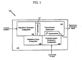
- NFME 100 is comprised generally of a waveform generator subsystem 102, a transmission subsystem 104, a communication modulation subsystem 106 and a reference clock subsystem 108.
- all of these components are provided on a single circuit card assembly 110.
- all of the components are provided in a single modular assembly, which may have multiple internal circuit cards, but which as an assembly is modular in nature and treated as a unitary component.
- a circuit card assemble 110 is understood and appreciated to encompass both a physical single card as well as the unitary component assembly.
- the NFME 100 can, on a pulse-to-pulse basis, generate a radar pulse or a communications pulse, all with the same set of hardware components.
- the NFME 100 takes advantage of a combination of direct digital synthesis and indirect frequency synthesis techniques to generate a suitable frequency plan to accommodate both radar and communications bands and contains an integral quadraphase-shift keying module for generating modulated communication or phase coded radar signals for transmission.
- the waveform generator 102 is a direct digital synthesis (DDS) waveform generator, and is operable to perform two functions.
- DDS direct digital synthesis
- FPGA field programmable gate array
- the DDS provides programmable waveforms in time, duration, slope and frequency.
- the transmission subsystem 104 is coupled to the waveform generator 102 and has a first upconverter 112 (coupled to the waveform generator) and a second upconverter 114.
- the communication modulation subsystem 106 is coupled to the second upconverter 114 of the transmission subsystem.
- the reference clock subsystem is coupled to the waveform generator, the transmission subsystem 104 and the communication modulation subsystem 106.
- the waveform generator 102 has a DDS chip featuring a 10-bit digital-to-analog converter (DAC) which operates at up to 1 GSPS and enables fast frequency hopping and fine tuning by employing a 32-bit frequency tuning word.
- the DDS clock frequency can run up to 1 GHz, providing greater than 300 MHz of useful Linear Frequency Modulation (LFM) bandwidth at the DDS output.
- LFM Linear Frequency Modulation
- the LFM waveforms are fully programmable in time, duration, slope and starting frequency which permits pre-distortion of the LFM waveform to compensate for phase distortion which may be introduced by the rest of the NFME 100 system. This pre-distortion compensation can be used to improve the radar range sidelobe performance of the generated radar waveform.
- the generated waveform output from the waveform generator subsystem 102 is provided to the first upconverter 112.
- the first upconverter 112 is a Ku-band Phase Lock Loop (PLL) subsystem.
- PLL Phase Lock Loop
- the first upconverter 112 multiplies this to a range of about 17.10-19.85 GHz.
- the first upconverter 112 in at least one embodiment is also operable as a waveform stretcher.
- NFME 100 is a circuit card assembly comprising a waveform generator subsystem, a transmission subsystem coupled to the waveform generator and having a first and second upconverter, a communication modulation subsystem coupled to the second upconverter and a reference clock subsystem that is coupled to the waveform generator subsystem, the transmission subsystem and the communication subsystem.
- this circuit card assembly is structured and arranged to comply with the Standard Avionics Module (SAM) format as used in advanced airborne radar platforms.
- SAM Standard Avionics Module
- FIG. 2 conceptually illustrates these two options in at least one method 200 of operation for NFME 100 to interleave radar and communication transmissions. It is of course understood and appreciated that this method need not be presented in the order herein presented, but rather this order is exemplary of at least one embodiment and is presented as shown to facilitate ease of discussion and illustration and not for purposes of limitation.
- method 200 generally is commenced with NFME 100 receiving a transmit directive, block 202.
- This directive is reviewed to determine the form of the transmission that is being directed, radar or communication, decision block 204.
- NFME 100 operates to generate an oscillating reference waveform with waveform generator subsystem 102 as described above, block 206.
- This oscillating reference wave form is upconverted and stretched by the first upconverter 112 to Ku-band, block 208.
- the upconverted Ku-band waveform is upconverted yet again by the second upconverter 114 to a Ka-band waveform in a range of about 33.4 ⁇ 36GHz, block 210.
- This Ka-band waveform is then output by the transmission subsystem 104 as a radar pulse, block 212.
- the method 200 determines if it is still in operation such that it should cycle back to receive yet another transmission directive, decision 214 returning to block 202.
- the waveform generator subsystem 102 is parked at a predetermined frequency that is appropriate for the type of communication to be performed, block 216. At this predetermined frequency a fixed frequency signal is then generated, block 218. This fixed frequency signal is upconverted by the first upconverter 112 as a Ku-band signal, block 220.
- the communication modulation system 106 receives communication data, such as identification data (and more specifically combat identification data) or data link information, and modulates this received communication data onto a selected channel at a lower frequency, block 222.
- NFME 100 can switch operation mode to be a continuous communication system. Although this would preclude the inter-leaving of radar pulses, such continuous communication may at times be desired, and the capability of NFME 100 to switch between pulse and continuous communication may be highly advantageous.
- method 200 permits NFME 100 to interleave radar and communication signals through the same device.
- the generated radar signals are of course established in over the frequency range appropriate for the type of radar operation to be performed.
- the communication signals include the transmission of data information and identification information, such as for example the specific form of combat identification information.
- FIG. 3 presents a schematic illustration further detailing the communication and flow of operations within at least one embodiment of NFME 100 as shown more generally in FIG. 1 . More specifically, the waveform generator subsystem 102 is shown to consist of two inner components, the programmable waveform generator 300 and the control subsystem 302.
- the reference subsystem 108 includes a crystal oscillator, which in at least one embodiment is a 100MHz crystal oscillator. In at least one alternative embodiment the reference subsystem 108 includes a crystal oscillator which is a 120MHz crystal oscillator.
- the reference system provides a reference clock signal 304 to the waveform generator subsystem 102, a fixed local oscillator frequency signal 306 to the first upconverter 112, and a transmission local oscillator frequency signal 308 to the second upconverter 114.
- the reference subsystem also provides a communication offset local oscillation signal 310 used in the channel selection phase lock loop and a communication modulation local oscillator frequency signal 312 used as a carrier for the communication modulation subsystem 106.
- the communication modulation subsystem 106 includes a quadrature phase-shift keying subsystem 314 for modulating digital signals on to a radio-frequency carrier signal using four phase states to code two digital bits.
- phase-shift keying is a digital modulation scheme to convey data by changing or modulating the phase of a reference signal (e.g., the carrier wave).
- the simplest form of PSK is binary phase-shift keying (BPSK) where the two phases are separated by one hundred eighty degrees.
- Quadraphase-shift keying (QPSK) uses four phases at ninety degree offsets which permits the encoding at twice the rate of BPSK.
- NFME 100 utilizes a QPSK subsystem 314 to provide QPSK for communication information encoding.
- QPSK subsystem 314 is providing four phases, it can be advantageously utilized to emulate a BPSK subsystem and provide bi-phase modulation for the generation of BPSK radar signals, which are also provided by NFME 100 and would apply to another class of radar.
- the same antenna structure is used to both transmit and receive, it is understood and appreciated that the NFME 100 operates to blank the transmit signal sent to the antenna so as to provide an opportunity for reception. This is especially important with respect to when NFME is operating in radar format.
- the reference subsystem 108 provides a transmission radar local oscillation signal 316 to the transmit subsystem 104, and more specifically to the blanking subsystem 318 within the transmission subsystem 104.
- the blanking subsystem 318 is a switch that turns off the signals when blanking is to occur.
- this waveform generator is in at least one embodiment a direct digital synthesis generator, which is preferable in many situations due to the beneficial ability to characterize the entire system to correct for non-linearities much more easily than with traditional analog generators.
- DDS generators may also provide spurs in the generated waveform signal.
- the output of the waveform generator subsystem 102 is passed to the first upconverter 112.
- the first upconverter and range multiplier 112 e.g., a Ku-band PLL
- NFME 100 not only enjoys the first upconversion of the generated signal, but the Ku-band PLL also acts as an active filter which removes the undesired spurs from the generated signal.
- the waveform generator subsystem 102 includes a control subsystem 302.
- the reference subsystem 108 provides the 100MHz oscillation signal that is used by the NFME 100 to synchronize actions of the NFME 100
- the control subsystem 302 is operable to direct when an action is to occur.
- Control subsystem 302 is therefore shown to have communication lines 320 and 322 leading to the transmission subsystem 104 and the communication modulation subsystem 106.
- Command of the waveform generator subsystem 102, and specifically the control subsystem 302 is overseen in at least one embodiment by the pre-processor system 324, which directs the type of transmission that is to be performed, e.g., radar or communication.
- the communication modulation subsystem 106 receives data for transmission. This data is modulated onto an RF carrier by the QPSK subsystem 314. The modulated RF carrier is upconverted to X band frequency by the communication modulation subsystem 106. This modulated X band signal is upconverted by the second upconverter 114 with the Ku-band fixed frequency signal provided by the first upconverter 112.
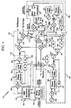
- FIG. 4 is a more refined system block diagram of NFME 100 further illustrating for at least one embodiment the components of the transmission subsystem 104, the communication modulation subsystem 106 and the reference clock subsystem 108.
- the output of the DDS waveform generator 300 is directed through to a mixer 400 which combines the signals received (e.g., the output of the DDS waveform generator 300 and the divided output provided from the reference subsystem 108 ) and generates an RF output signal within a baseband frequency range of about 118 MHz ⁇ 291 MHz.
- the output signal is permitted to vary, whereas for communication format it may be selected to a pre-determined low spurious fixed frequency signal.
- This RF output from mixer 400 is directed through a phase detector 402, a loop filter 404, a voltage controllable oscillator 406 and one or more frequency divider circuits 408 (e.g., divide by 2), 410 (e.g., divide by 8).
- these elements provide the Ku-band PLL 112.
- the output of the Ku-band PLL 112 is directed to yet another mixer 412 which may selectively receive a signal from the reference subsystem 108, the mixed output being provided to a splitter 414 directing to a receiver and through yet another mixer 416 to the transmission amp.
- the additional mixer 416 is coupled to a switch 418 so as to permit blanking of the transmitter or receipt of a signal from the communication modulation subsystem 106.
- the reference subsystem 108 in at least one embodiment is fundamentally based upon an oscillator, and more specifically a crystal oscillator 420.
- the output of the oscillator may be divided by a frequency divider 422 to a desired frequency and directed through a phase detector 424, a loop filter 426, a voltage controllable oscillator 428, and one or more frequency divider circuits 430 (e.g., divide by 32).
- This reference signal is then passed through additional splitters 434, 435, frequency divider circuits 436 (e.g., divide by 4), 438 (e.g., divide by 2), one or more frequency multiplier circuits 440 (e.g., multiply by 2), mixers 442, 444 and splitters 446, 448,450 to provide the appropriate reference signals as desired for the waveform generation subsystem 102, the transmission subsystem 104 and the communication modulation subsystem 106.
- frequency divider circuits 436 e.g., divide by 4
- 438 e.g., divide by 2
- one or more frequency multiplier circuits 440 e.g., multiply by 2
- mixers 442, 444 and splitters 446, 448,450 e.g., mixers 442, 444 and splitters 446, 448,450
- the communication modulation subsystem 106 receives input from the reference subsystem 108 in the form of two signals 310, 312.
- Signal 312 is passed through a splitter 470 and passed to frequency divider 472 (e.g., divide by 48) to become the reference for the phase lock loop as provided by a phase detector 474, a loop filter 476, and a voltage controllable oscillator 478.
- Signal 310 is a passed to a mixer 480 which receives input from the voltage controllable oscillator 478, and provides output to an adjustable frequency divider 482 which is in turn input to the phase detector 474.
- the adjustable frequency divider 482 is programmable and provides channel selection.
- the output of the loop is provided to a splitter 484 with one output directed to an option receiver for channel selection during receive.
- the other signal path goes through switch 486.
- the switch When operating in radar mode, the switch is set to a load 488 so as to defeat the signal.
- the switch When operating in communication mode the switch provides the signal to a mixer 490 which also receives the modulated carrier with communication information as provided by the modulator 492, which receives the communication information desired for transmission.
- the transmission subsystem 104 receives linear and non-linear phase modulated signals via the waveform generator 102, which are upconverted, filtered and input to mixers 412 and 416.
- the local oscillator signal to mixer 416 comes from the reference subsystem 108.
- the waveform generator 102 is tuned to a spur free fixed frequency and the upconverted and phase encoded signal input to mixer 416 is from the communication modulation subsystem 106. The tuning of the waveform generator 102 to a spur free fixed frequency eliminates DDS spurs from degrading the communications signal.
- NFME 100 operable to interleave transmission signals for transmission
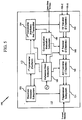
- NFME 100 includes components for reception as well. Such an embodiment is set forth in FIG. 4 .
- NFME 100 includes an RF receiver 500 coupled to the transmission subsystem 104.
- the RF receiver 500 is coupled to an intermediate frequency (IF) receiver 502.
- the IF receiver 502 is coupled to the reference clock subsystem 108 and the communication modulation subsystem 106 so as to be properly synchronized and modulated for the extraction of information from the received signal.
- the output of the IF receiver 502 is coupled to an analog to digital (A/D) converter 504, which in turn is coupled to the preprocessor subsystem 324.
- A/D analog to digital
Landscapes
- Engineering & Computer Science (AREA)
- Computer Networks & Wireless Communication (AREA)
- Physics & Mathematics (AREA)
- General Physics & Mathematics (AREA)
- Radar, Positioning & Navigation (AREA)
- Remote Sensing (AREA)
- Radar Systems Or Details Thereof (AREA)
- Digital Transmission Methods That Use Modulated Carrier Waves (AREA)
Description
- This application claims priority to
U.S. Provisional Application 60/019.758 filed January 8, 2008 , entitled "A Non-Federated Multi-Function KA-Band Exciter System and Method". - This invention relates generally to the field of signal processors and processing systems in radar and communication systems, and more specifically to a non-federated multi-function Ka-band exciter system.
- In recent years, the United States military has systematically moved from conventional weaponry to systems and devices using advanced global positioning satellite systems, radar systems and communication systems. Indeed the need for a weapon system or reconnaissance system, whether manned or unmanned, to have communication capabilities is nearly an absolute must.
- More and more defense systems are implemented with the use of multiple actors and therefore require communication with a base, if not cross communication while in the field. At high rates of speed, long distances and perhaps even the use of camouflage communication also may be vital to the identification of and distinction between friend and foe. And it not uncommon for manned and unmanned vehicles to employ many types of radar and communication systems.
- In addition, there is an ever increasing realization that customized components are not always cost effective or easily upgraded with new technology. Moreover, radar and communication systems that are readily adaptable for use in different aircraft, and or ground vehicles are likely to enjoy cost savings in production. Systems that can utilize existing interfaces are also more easily installed, replaced and/or upgraded when and as needed.
- With respect to moving systems such as aircraft and cruise missiles, weight is on important design factor. Although important, multiple communication and radar systems tend to increase the overall weight of a craft, and therefore either reduce the amount of payload or shielding that that can be carried, or necessitates the use of larger engines. This also factors into increased costs in design and development. Even with ground based systems such as vehicles or systems that are carried by persons themselves, communication systems are vitally important.
- In many instances there are common elements between the multiple communication and radar systems, which implies that to some extent the excess weight is redundant weight. Maintenance is also a factor and as the communication systems are vital to device and system performance, routine maintenance is a regular and necessary occurrence. When multiple systems have multiple common elements, the costs of this routine maintenance may be somewhat inflated due to redundant maintenance being performed on similar but separate systems within the same aircraft.
- Moreover, the redundant elements necessary to excite the various waveforms used for the communication signals and radar signals affects the cost, size and weight of the system both for its development as well as for its continued use.
- Hence, there "is a need for a non-federated multi-function exciter that overcomes one or more of the issues and problems identified above.
A prior art vehicle communication network is known fromUS2002003488A1 . Therein is disclosed a system consisting of: an antenna array, which consists of at least one antenna, the array used to provide spatial resolution between radar targets, measurements of bearing to the targets, as well as cancellation of unwanted interfering signals; an RF front end is coupled to antenna array, the RF front end transmitting the required waveforms and receiving the radar echo or the incoming information transmission; a waveform generator coupled to RF front end, the waveform generator receiving, from a radar processor and a communication processor, the required waveforms and the information to be transmitted, the waveform generator synthesizing a combined waveform to be transmitted by the RF front end; and a Comm/Radar splitter coupled between RF front end and Communication processor, the Comm/Radar splitter splitings the received signal to a radar signal (by canceling the known transmitted information signal out of the received signal) and a communication signal (by canceling the radar signal) for conveyence to the appropriate processor-the radar processor or the communication processor. The radar processor analyzes the raw data received by the RF front end. The radar processor performs target detection using digital radar signal processing and constructs the three-dimensional Range-Doppler-Azimuth map. The radar processor produce track files, each representing the dynamic of a near by object and alerting as to potential hazardous objects. The communication processor supports the communication link. In ISO's OSI model definition, the communication processor supports the six lowest layers out of the seven communication layers. The seventh layer, the application layer, is handled in an information processor. The information processor supports communication standards in the relevant frequency bands.
A prior art multi-mode radar exciter is known fromUS6081226A . A prior art Inter-vehicle communication and warning apparatus is known fromUS2007096885A1 . A prior art method and system for radar compatible data communication is known fromUS4733238A . A prior art multi-mode radar system having real-time ultra high resolution synthetic aperture radar (SAR) capability is known fromUS5708436A . A prior art digital signal processor exciter is known fromUS5418818A . - In accordance with the present invention, there is provided a non-federated multi-function exciter and method according to
claim 1 and 10. -
-
FIG. 1 is a block diagram of a non-federated multi-function exciter in accordance with at least one embodiment; -
FIG. 2 is a flow diagram for at least one method of operation for the non- federated multi-function exciter as shown inFIG. 1 ; -
FIG. 3 presents the flow of communication and control for a non-federated multi-function exciter as shown inFIG. I in accordance with at least one embodiment; -
FIG. 4 presents a high level circuit schematic diagram of the non-federated multi-function exciter as shown inFIG. 3 in accordance with at least one embodiment; and -
FIG. 5 presents at least one alternative embodiment for a non-federated multi-function exciter as shown inFIG. 1 further including receiver components in accordance with at least one embodiment; - Before proceeding with the detailed description, it is to be appreciated that the present teaching is by way of example only, not by limitation. The concepts herein are not limited to use or application with a specific system or method of a non-federated multi-function exciter. Thus, although the instrumentalities described herein are for the convenience of explanation, shown and described with respect to exemplary embodiments, it will be appreciated that the principles herein may be applied equally in other types of systems and methods involving non-federated multi-function exciters; including but not limited to pulsed radar, frequency modulated continuous wave (FMCW) radar, pulsed communications, CW communications, datalink, combat identification, etc.
- Turning now to the figures, and more specifically to
FIG. 1 , there is shown a conceptual block diagram of a non-federated multi-function exciter "NFME" 100 in accordance with at least one embodiment. As shown, NFME 100 is comprised generally of awaveform generator subsystem 102, atransmission subsystem 104, acommunication modulation subsystem 106 and areference clock subsystem 108. In at least one embodiment, all of these components are provided on a singlecircuit card assembly 110. In at least one embodiment, all of the components are provided in a single modular assembly, which may have multiple internal circuit cards, but which as an assembly is modular in nature and treated as a unitary component. For purposes of this disclosure, a circuit card assemble 110 is understood and appreciated to encompass both a physical single card as well as the unitary component assembly. - As is further discussed below, through the use of an interleaved mode waveform, the NFME 100 can, on a pulse-to-pulse basis, generate a radar pulse or a communications pulse, all with the same set of hardware components. The NFME 100 takes advantage of a combination of direct digital synthesis and indirect frequency synthesis techniques to generate a suitable frequency plan to accommodate both radar and communications bands and contains an integral quadraphase-shift keying module for generating modulated communication or phase coded radar signals for transmission.
- In at least one embodiment, the
waveform generator 102 is a direct digital synthesis (DDS) waveform generator, and is operable to perform two functions. First, a field programmable gate array (FPGA) within the DDS provides timing and control functions for the DDS subsystem itself as well as for the rest of the NFME 100. Second, the DDS provides programmable waveforms in time, duration, slope and frequency. - As a general overview, the
transmission subsystem 104 is coupled to thewaveform generator 102 and has a first upconverter 112 (coupled to the waveform generator) and asecond upconverter 114. Thecommunication modulation subsystem 106 is coupled to thesecond upconverter 114 of the transmission subsystem. The reference clock subsystem is coupled to the waveform generator, thetransmission subsystem 104 and thecommunication modulation subsystem 106. - More specifically, in at least one preferred embodiment the
waveform generator 102 has a DDS chip featuring a 10-bit digital-to-analog converter (DAC) which operates at up to 1 GSPS and enables fast frequency hopping and fine tuning by employing a 32-bit frequency tuning word. The DDS clock frequency can run up to 1 GHz, providing greater than 300 MHz of useful Linear Frequency Modulation (LFM) bandwidth at the DDS output. - The LFM waveforms are fully programmable in time, duration, slope and starting frequency which permits pre-distortion of the LFM waveform to compensate for phase distortion which may be introduced by the rest of the
NFME 100 system. This pre-distortion compensation can be used to improve the radar range sidelobe performance of the generated radar waveform. - The generated waveform output from the
waveform generator subsystem 102 is provided to thefirst upconverter 112. In at least one embodiment, thefirst upconverter 112 is a Ku-band Phase Lock Loop (PLL) subsystem. As the output waveform from thewaveform generator subsystem 102 is generally in a range of about 118-291 MHz, thefirst upconverter 112 multiplies this to a range of about 17.10-19.85 GHz. Moreover, thefirst upconverter 112 in at least one embodiment is also operable as a waveform stretcher. - Moreover, with respect to
FIG. 1 , in at least oneembodiment NFME 100 is a circuit card assembly comprising a waveform generator subsystem, a transmission subsystem coupled to the waveform generator and having a first and second upconverter, a communication modulation subsystem coupled to the second upconverter and a reference clock subsystem that is coupled to the waveform generator subsystem, the transmission subsystem and the communication subsystem. In at least one embodiment this circuit card assembly is structured and arranged to comply with the Standard Avionics Module (SAM) format as used in advanced airborne radar platforms. - As
NFME 100 is operable in either a radar format or a communication format, there are two general signal flow paths that may be taken with respect to this upconverted waveform.FIG. 2 conceptually illustrates these two options in at least onemethod 200 of operation forNFME 100 to interleave radar and communication transmissions. It is of course understood and appreciated that this method need not be presented in the order herein presented, but rather this order is exemplary of at least one embodiment and is presented as shown to facilitate ease of discussion and illustration and not for purposes of limitation. - As shown in
FIG. 2 ,method 200 generally is commenced withNFME 100 receiving a transmit directive, block 202. This directive is reviewed to determine the form of the transmission that is being directed, radar or communication,decision block 204. - In a first instance, radar format,
NFME 100 operates to generate an oscillating reference waveform withwaveform generator subsystem 102 as described above, block 206. This oscillating reference wave form is upconverted and stretched by thefirst upconverter 112 to Ku-band, block 208. The upconverted Ku-band waveform is upconverted yet again by thesecond upconverter 114 to a Ka-band waveform in a range of about 33.4∼36GHz, block 210. This Ka-band waveform is then output by thetransmission subsystem 104 as a radar pulse, block 212. - The
method 200 then determines if it is still in operation such that it should cycle back to receive yet another transmission directive,decision 214 returning to block 202. - In the second instance, communication format, the
waveform generator subsystem 102 is parked at a predetermined frequency that is appropriate for the type of communication to be performed, block 216. At this predetermined frequency a fixed frequency signal is then generated, block 218. This fixed frequency signal is upconverted by thefirst upconverter 112 as a Ku-band signal, block 220. Thecommunication modulation system 106 receives communication data, such as identification data (and more specifically combat identification data) or data link information, and modulates this received communication data onto a selected channel at a lower frequency, block 222. - This modulated signal is then upconverted by the fixed frequency Ku-band signal and the
second upconverter 114 to a Ka-band waveform in the range of about 36.0∼38.6 GHz, block 224. This Ka-band signal is then output by thetransmission subsystem 106 as a communication pulse, block 226. As in the first instance of radar format, themethod 200 then determines if it is still in operation, and cycles back to receive yet another transmission directive if such is the case,decision 214 returning to block 202. It should be noted that in at least one embodiment,NFME 100 can switch operation mode to be a continuous communication system. Although this would preclude the inter-leaving of radar pulses, such continuous communication may at times be desired, and the capability ofNFME 100 to switch between pulse and continuous communication may be highly advantageous. - In such a fashion,
method 200 permits NFME 100 to interleave radar and communication signals through the same device. The generated radar signals are of course established in over the frequency range appropriate for the type of radar operation to be performed. Similarly, the communication signals include the transmission of data information and identification information, such as for example the specific form of combat identification information. -
FIG. 3 presents a schematic illustration further detailing the communication and flow of operations within at least one embodiment ofNFME 100 as shown more generally inFIG. 1 . More specifically, thewaveform generator subsystem 102 is shown to consist of two inner components, theprogrammable waveform generator 300 and thecontrol subsystem 302. - The
reference subsystem 108 includes a crystal oscillator, which in at least one embodiment is a 100MHz crystal oscillator. In at least one alternative embodiment thereference subsystem 108 includes a crystal oscillator which is a 120MHz crystal oscillator. The reference system provides areference clock signal 304 to thewaveform generator subsystem 102, a fixed localoscillator frequency signal 306 to thefirst upconverter 112, and a transmission localoscillator frequency signal 308 to thesecond upconverter 114. The reference subsystem also provides a communication offsetlocal oscillation signal 310 used in the channel selection phase lock loop and a communication modulation localoscillator frequency signal 312 used as a carrier for thecommunication modulation subsystem 106. - The
communication modulation subsystem 106 includes a quadrature phase-shift keying subsystem 314 for modulating digital signals on to a radio-frequency carrier signal using four phase states to code two digital bits. Moreover, phase-shift keying (PSK) is a digital modulation scheme to convey data by changing or modulating the phase of a reference signal (e.g., the carrier wave). The simplest form of PSK is binary phase-shift keying (BPSK) where the two phases are separated by one hundred eighty degrees. Quadraphase-shift keying (QPSK) uses four phases at ninety degree offsets which permits the encoding at twice the rate of BPSK. - In at least one embodiment,
NFME 100 utilizes aQPSK subsystem 314 to provide QPSK for communication information encoding. As theQPSK subsystem 314 is providing four phases, it can be advantageously utilized to emulate a BPSK subsystem and provide bi-phase modulation for the generation of BPSK radar signals, which are also provided byNFME 100 and would apply to another class of radar. - As in at least one embodiment the same antenna structure, not shown, is used to both transmit and receive, it is understood and appreciated that the
NFME 100 operates to blank the transmit signal sent to the antenna so as to provide an opportunity for reception. This is especially important with respect to when NFME is operating in radar format. Accordingly, thereference subsystem 108 provides a transmission radarlocal oscillation signal 316 to the transmitsubsystem 104, and more specifically to theblanking subsystem 318 within thetransmission subsystem 104. Theblanking subsystem 318 is a switch that turns off the signals when blanking is to occur. - With respect to the
waveform generator subsystem 102, and theprogrammable waveform generator 300 specifically, as noted above this waveform generator is in at least one embodiment a direct digital synthesis generator, which is preferable in many situations due to the beneficial ability to characterize the entire system to correct for non-linearities much more easily than with traditional analog generators. However, it is also understood and appreciated that DDS generators may also provide spurs in the generated waveform signal. - As indicated by
connection path 318, the output of thewaveform generator subsystem 102 is passed to thefirst upconverter 112. By passing the output of thewaveform generator subsystem 102 to the first upconverter andrange multiplier 112, e.g., a Ku-band PLL,NFME 100 not only enjoys the first upconversion of the generated signal, but the Ku-band PLL also acts as an active filter which removes the undesired spurs from the generated signal. - As noted above the
waveform generator subsystem 102 includes acontrol subsystem 302. Whereas thereference subsystem 108 provides the 100MHz oscillation signal that is used by theNFME 100 to synchronize actions of theNFME 100, thecontrol subsystem 302 is operable to direct when an action is to occur.Control subsystem 302 is therefore shown to havecommunication lines transmission subsystem 104 and thecommunication modulation subsystem 106. Command of thewaveform generator subsystem 102, and specifically thecontrol subsystem 302 is overseen in at least one embodiment by thepre-processor system 324, which directs the type of transmission that is to be performed, e.g., radar or communication. - As noted above, when operating in communication format, the
communication modulation subsystem 106 receives data for transmission. This data is modulated onto an RF carrier by theQPSK subsystem 314. The modulated RF carrier is upconverted to X band frequency by thecommunication modulation subsystem 106. This modulated X band signal is upconverted by thesecond upconverter 114 with the Ku-band fixed frequency signal provided by thefirst upconverter 112. -
FIG. 4 is a more refined system block diagram ofNFME 100 further illustrating for at least one embodiment the components of thetransmission subsystem 104, thecommunication modulation subsystem 106 and thereference clock subsystem 108. - More specifically, the output of the
DDS waveform generator 300 is directed through to amixer 400 which combines the signals received (e.g., the output of theDDS waveform generator 300 and the divided output provided from the reference subsystem 108) and generates an RF output signal within a baseband frequency range of about 118 MHz ∼ 291 MHz. For radar format the output signal is permitted to vary, whereas for communication format it may be selected to a pre-determined low spurious fixed frequency signal. - This RF output from
mixer 400 is directed through aphase detector 402, aloop filter 404, a voltagecontrollable oscillator 406 and one or more frequency divider circuits 408 (e.g., divide by 2), 410 (e.g., divide by 8). Collectively, these elements provide the Ku-band PLL 112. The output of the Ku-band PLL 112 is directed to yet anothermixer 412 which may selectively receive a signal from thereference subsystem 108, the mixed output being provided to asplitter 414 directing to a receiver and through yet anothermixer 416 to the transmission amp. Theadditional mixer 416 is coupled to aswitch 418 so as to permit blanking of the transmitter or receipt of a signal from thecommunication modulation subsystem 106. - The
reference subsystem 108 in at least one embodiment is fundamentally based upon an oscillator, and more specifically acrystal oscillator 420. The output of the oscillator may be divided by afrequency divider 422 to a desired frequency and directed through aphase detector 424, aloop filter 426, a voltagecontrollable oscillator 428, and one or more frequency divider circuits 430 (e.g., divide by 32). - This reference signal is then passed through
additional splitters mixers splitters 446, 448,450 to provide the appropriate reference signals as desired for thewaveform generation subsystem 102, thetransmission subsystem 104 and thecommunication modulation subsystem 106. - The
communication modulation subsystem 106 receives input from thereference subsystem 108 in the form of twosignals Signal 312 is passed through asplitter 470 and passed to frequency divider 472 (e.g., divide by 48) to become the reference for the phase lock loop as provided by aphase detector 474, a loop filter 476, and a voltagecontrollable oscillator 478.Signal 310 is a passed to amixer 480 which receives input from the voltagecontrollable oscillator 478, and provides output to anadjustable frequency divider 482 which is in turn input to thephase detector 474. Theadjustable frequency divider 482 is programmable and provides channel selection. - The output of the loop is provided to a
splitter 484 with one output directed to an option receiver for channel selection during receive. The other signal path goes throughswitch 486. When operating in radar mode, the switch is set to aload 488 so as to defeat the signal. When operating in communication mode the switch provides the signal to amixer 490 which also receives the modulated carrier with communication information as provided by themodulator 492, which receives the communication information desired for transmission. - When in radar mode, the
transmission subsystem 104 receives linear and non-linear phase modulated signals via thewaveform generator 102, which are upconverted, filtered and input tomixers mixer 416 comes from thereference subsystem 108. In the communication mode, thewaveform generator 102 is tuned to a spur free fixed frequency and the upconverted and phase encoded signal input tomixer 416 is from thecommunication modulation subsystem 106. The tuning of thewaveform generator 102 to a spur free fixed frequency eliminates DDS spurs from degrading the communications signal. - Whereas the above discussion and figures relate to an embodiment of
NFME 100 operable to interleave transmission signals for transmission, in at least one alternative embodiment,NFME 100 includes components for reception as well. Such an embodiment is set forth inFIG. 4 . - More specifically, in at least one embodiment as shown in
FIG. 5 ,NFME 100 includes anRF receiver 500 coupled to thetransmission subsystem 104. TheRF receiver 500 is coupled to an intermediate frequency (IF)receiver 502. TheIF receiver 502 is coupled to thereference clock subsystem 108 and thecommunication modulation subsystem 106 so as to be properly synchronized and modulated for the extraction of information from the received signal. - The output of the
IF receiver 502 is coupled to an analog to digital (A/D)converter 504, which in turn is coupled to thepreprocessor subsystem 324.
Claims (10)
- A non-federated multi-function exciter (100) to generate interleaved radar and communication signals, comprising:a waveform generator subsystem (102) operable to provide waveforms programmable in time, duration, slope and frequency;a transmission subsystem (104) coupled to the waveform generator subsystem, the transmission subsystem having a Ku-band PLL subsystem as a first upconverter (112) and a second upconverter (114) coupled to the first upconverter,a communication modulation subsystem (106) coupled to the second upconverter of the transmission subsystem; anda reference clock subsystem (108) coupled to the waveform generator subsystem, the transmission subsystem and the communication modulation subsystem;wherein the exciter operates in a first instance of radar format to:generate an oscillating reference waveform using the waveform generator subsystem;upconvert the oscillating reference waveform to a Ku-band waveform using the first upconverter, andupconvert the Ku-band waveform to a Ka-band waveform using the second upconverter, and transmit the generated Ka-band waveform as a radar signal; andwherein the exciter operates in a second instance of communication format to:park the waveform generator subsystem at a predetermined frequency to generate a low spurious content fixed frequency signal;upconvert the fixed frequency signal to a fixed frequency Ku-band signal using the first upconverter;modulate received communication information using the communication modulation subsystem;upconvert the modulated communication information with the fixed frequency Ku-band signal using the second upconverter to a modulated Ka-band signal; andtransmit the modulated Ka-band signal as a pulse of communication data.
- The non-federated multi-function exciter of claim 1, wherein the communication signals are selected from the group consisting of data information and identification information.
- The non-federated multi-function exciter of claim 2, wherein the identification information is combat identification information.
- The non-federated multi-function exciter of claim 1, wherein the Ku-band PLL subsystem is operable as on active filter, a waveform stretcher, and an upconverter.
- The non-federated multi-function exciter of claim 1, wherein the communication modulation subsystem includes a quad-phase shift key modulator.
- The non-federated multi-function exciter of claim 5, wherein the quad-phase modulator is operable to provide bi-phase modulation.
- The non-federated multi-function exciter of claim 1, wherein the waveform generator subsystem is a direct digital synthesis waveform generator.
- The non-federated multi-function exciter of claim 1, wherein the waveform generator subsystem, the transmission subsystem, the communication modulation subsystem and the reference clock subsystem are disposed as a single circuit card assembly.
- The non-federated multi-function exciter of claim 1, further including:an RF receiver coupled to the transmission subsystem;an IF receiver coupled to the RF receiver, the communication modulation subsystem and the reference clock subsystem; andan A/D converter coupled to the IF receiver and the reference clock subsystem.
- A method of generating interleaved radar and communication signals using a non-federated multi-function exciter, comprising:determining (202,204) the transmission operation to be in a first instance a radar format and in a second instance to be a communication format;in the first instance of radar format:generating (206) an oscillating reference waveform using a waveform generator subsystem;upconverting (208) the oscillating reference waveform to a Ku-band waveform using a Ku-band PLL subsystem as a first upconverter of a transmission subsystem, andupconverting (210) the Ku-band waveform to a Ka-band waveform using a second upconverter of the transmission subsystem, and transmitting the generated Ka-band waveform as a radar signal;in the second instance of communication format:parking (216, 218) the waveform generator subsystem at a predetermined frequency to generate a fixed frequency signal;upconverting (220) the fixed frequency signal to a fixed frequency Ku-band signal using the Ku-band PLL subsystem;modulating (222) received communication information using a communication modulation subsystem;upconverting (224) the modulated communication information with the fixed frequency Ku-band signal using the second upconverter of the transmission subsystem to a modulated Ka-band signal; andtransmitting (226) the modulated Ka-band signal as a pulse of communication data.
Applications Claiming Priority (2)
| Application Number | Priority Date | Filing Date | Title |
|---|---|---|---|
| US12/106,865 US8254433B2 (en) | 2008-01-08 | 2008-04-21 | Non-federated multi-function Ka-band exciter system and method |
| PCT/US2009/041317 WO2009140032A1 (en) | 2008-04-21 | 2009-04-21 | A non-federated multi-function ka-band exciter system and method |
Publications (3)
| Publication Number | Publication Date |
|---|---|
| EP2274638A1 EP2274638A1 (en) | 2011-01-19 |
| EP2274638A4 EP2274638A4 (en) | 2011-08-17 |
| EP2274638B1 true EP2274638B1 (en) | 2017-05-17 |
Family
ID=41318996
Family Applications (1)
| Application Number | Title | Priority Date | Filing Date |
|---|---|---|---|
| EP09747118.9A Not-in-force EP2274638B1 (en) | 2008-04-21 | 2009-04-21 | A non-federated multi-function ka-band exciter system and method |
Country Status (3)
| Country | Link |
|---|---|
| US (1) | US8254433B2 (en) |
| EP (1) | EP2274638B1 (en) |
| WO (1) | WO2009140032A1 (en) |
Families Citing this family (19)
| Publication number | Priority date | Publication date | Assignee | Title |
|---|---|---|---|---|
| US7965226B2 (en) * | 2009-03-31 | 2011-06-21 | Raytheon Company | Agile beam pulse to pulse interleaved radar modes |
| DK2556385T3 (en) * | 2010-04-08 | 2014-06-10 | Elbit Systems Ew And Sigint Elisra Ltd | Electronic countermeasure system |
| US8606204B2 (en) * | 2010-04-14 | 2013-12-10 | John W. McCorkle | Coherent transceiver and related method of operation |
| US8730088B2 (en) * | 2010-08-09 | 2014-05-20 | Raytheon Bbn Technologies Corp. | Radar coherent processing interval scheduling via ad hoc network |
| US9618605B2 (en) * | 2011-12-30 | 2017-04-11 | Flir Systems, Inc. | Radar system providing multiple waveforms for long range and short range target detection |
| JP6512509B2 (en) * | 2015-03-11 | 2019-05-15 | パナソニックIpマネジメント株式会社 | Motion detector and lighting system |
| EP3321710B1 (en) * | 2016-11-09 | 2020-03-25 | NXP USA, Inc. | Apparatus and associated method |
| US10285190B2 (en) * | 2016-12-20 | 2019-05-07 | Raytheon Bbn Technologies Corp. | Scheduling access to a shared medium |
| US11375543B2 (en) * | 2017-01-10 | 2022-06-28 | Qualcomm Incorporated | Co-existence of millimeter wave communication and radar |
| US10333421B2 (en) * | 2017-03-30 | 2019-06-25 | Raytheon Company | Polymorphic waveform generation |
| US10914834B2 (en) | 2017-05-10 | 2021-02-09 | Google Llc | Low-power radar |
| US10782390B2 (en) | 2017-05-31 | 2020-09-22 | Google Llc | Full-duplex operation for radar sensing using wireless communication chipset |
| US10754005B2 (en) * | 2017-05-31 | 2020-08-25 | Google Llc | Radar modulation for radar sensing using a wireless communication chipset |
| US10795009B2 (en) | 2017-05-31 | 2020-10-06 | Google Llc | Digital beamforming for radar sensing using wireless communication chipset |
| CN113614676B (en) | 2019-05-20 | 2024-03-26 | 谷歌有限责任公司 | Mobile device-based radar system for providing a multi-mode interface and method thereof |
| JP7163513B2 (en) | 2019-06-17 | 2022-10-31 | グーグル エルエルシー | A mobile device-based radar system for applying different power modes to multimode interfaces |
| CN110988830A (en) * | 2020-01-03 | 2020-04-10 | 零八一电子集团有限公司 | Multi-frequency-band radar target simulator |
| US12199684B2 (en) | 2021-06-23 | 2025-01-14 | Samsung Electronics Co., Ltd. | Method and apparatus for multi panel radar operation |
| CN113740809A (en) * | 2021-09-10 | 2021-12-03 | 中国电波传播研究所(中国电子科技集团公司第二十二研究所) | Multi-channel extensible broadband excitation generation device and method |
Family Cites Families (11)
| Publication number | Priority date | Publication date | Assignee | Title |
|---|---|---|---|---|
| US3350651A (en) | 1964-12-18 | 1967-10-31 | Spectral Dynamics Corp | Waveform converters |
| US4216542A (en) | 1979-03-06 | 1980-08-05 | Nasa | Method and apparatus for quadriphase-shift-key and linear phase modulation |
| US4733238A (en) | 1986-11-17 | 1988-03-22 | Hughes Aircraft Company | Method and system for radar compatible data communication |
| US5120997A (en) | 1989-03-06 | 1992-06-09 | Raytheon Company | Spread spection signal detector |
| US5418818A (en) | 1992-09-22 | 1995-05-23 | Glenayre Electronics, Inc. | Digital signal processor exciter |
| US5594939A (en) * | 1992-11-23 | 1997-01-14 | Hughes Aircraft Company | Synthesizer routing architecture for a switching apparatus |
| US5708436A (en) | 1996-06-24 | 1998-01-13 | Northrop Grumman Corporation | Multi-mode radar system having real-time ultra high resolution synthetic aperture radar (SAR) capability |
| US6081226A (en) | 1998-07-10 | 2000-06-27 | Northrop Grumman Corporation | Multi-mode radar exciter |
| IL134518A0 (en) | 2000-02-13 | 2001-04-30 | Hexagon System Engineering Ltd | Integrated radar and communication system |
| FR2869743A1 (en) * | 2004-04-29 | 2005-11-04 | Thomson Licensing Sa | BI-DIRECTIONAL BROADCAST DIFFUSION USER TERMINAL WITH CONFIGURABLE TRANSMISSION FREQUENCIES |
| TWI287514B (en) | 2005-11-03 | 2007-10-01 | Ind Tech Res Inst | Inter-vehicle communication and warning apparatus |
-
2008
- 2008-04-21 US US12/106,865 patent/US8254433B2/en active Active
-
2009
- 2009-04-21 EP EP09747118.9A patent/EP2274638B1/en not_active Not-in-force
- 2009-04-21 WO PCT/US2009/041317 patent/WO2009140032A1/en not_active Ceased
Also Published As
| Publication number | Publication date |
|---|---|
| WO2009140032A1 (en) | 2009-11-19 |
| US8254433B2 (en) | 2012-08-28 |
| EP2274638A1 (en) | 2011-01-19 |
| US20090323782A1 (en) | 2009-12-31 |
| EP2274638A4 (en) | 2011-08-17 |
Similar Documents
| Publication | Publication Date | Title |
|---|---|---|
| US8254433B2 (en) | Non-federated multi-function Ka-band exciter system and method | |
| US11762077B2 (en) | Method and system for frequency offset modulation range division MIMO automotive radar using I-channel only modulation mixer | |
| US7737880B2 (en) | Microwave and millimeterwave radar sensors | |
| US20210173042A1 (en) | Method and System for Frequency Offset Modulation Range Division MIMO Automotive Radar | |
| EP2127066B1 (en) | Radar having a low noise frequency generator | |
| EP3346284B1 (en) | Synthesizer for radar sensing | |
| US20200326416A1 (en) | Miniaturized digital radar system | |
| CN104698458A (en) | Unmanned airborne system for SAR imaging and moving-target detection by utilizing Ka-frequency-band frequency modulated continuous waves | |
| Chan et al. | Synthetic aperture radar (SAR) signal generation | |
| CA2361015A1 (en) | Spread spectrum radar with leak compensation at baseband | |
| WO2001096901A2 (en) | Low probability of intercept coherent radar altimeter | |
| WO1988004061A1 (en) | Method and system for radar compatible data communication | |
| CN105044678B (en) | Radar response based on all-digital phase-locked loop framework/interference one wireless communication device | |
| JP2004271529A (en) | Radar signal transmission method, transmission method for multiple radar transmitters, radar, and radar transmitter | |
| Adler et al. | Direct digital synthesis applications for radar development | |
| CN119199825A (en) | Target detection method, electronic device and storage medium | |
| US7106245B2 (en) | Digital RF tag | |
| US20250293907A1 (en) | Signal processing system and related apparatus | |
| US20070080852A1 (en) | Phase locked loop as linear chirp extender | |
| KR101235057B1 (en) | Digital radio frequency memory | |
| US3378840A (en) | Transmitter system for aperture added radars | |
| KR20220072186A (en) | SAR SYSTEM BASED ON SoC TECHNOLOGY | |
| GB2268350A (en) | High range resolution radar | |
| Im et al. | An FMCW and chirp pulse‐doppler radar system for surveillance in X‐band | |
| Suna Yazar et al. | Frequency-shifted FMCW method against DRFM spoofing attacks |
Legal Events
| Date | Code | Title | Description |
|---|---|---|---|
| PUAI | Public reference made under article 153(3) epc to a published international application that has entered the european phase |
Free format text: ORIGINAL CODE: 0009012 |
|
| 17P | Request for examination filed |
Effective date: 20101108 |
|
| AK | Designated contracting states |
Kind code of ref document: A1 Designated state(s): AT BE BG CH CY CZ DE DK EE ES FI FR GB GR HR HU IE IS IT LI LT LU LV MC MK MT NL NO PL PT RO SE SI SK TR |
|
| AX | Request for extension of the european patent |
Extension state: AL BA RS |
|
| DAX | Request for extension of the european patent (deleted) | ||
| A4 | Supplementary search report drawn up and despatched |
Effective date: 20110718 |
|
| RIC1 | Information provided on ipc code assigned before grant |
Ipc: G01S 13/74 20060101AFI20110712BHEP |
|
| 17Q | First examination report despatched |
Effective date: 20120628 |
|
| REG | Reference to a national code |
Ref country code: DE Ref legal event code: R079 Ref document number: 602009046151 Country of ref document: DE Free format text: PREVIOUS MAIN CLASS: G01S0013740000 Ipc: G01S0007282000 |
|
| GRAP | Despatch of communication of intention to grant a patent |
Free format text: ORIGINAL CODE: EPIDOSNIGR1 |
|
| RIC1 | Information provided on ipc code assigned before grant |
Ipc: G01S 7/282 20060101AFI20161013BHEP |
|
| RIN1 | Information on inventor provided before grant (corrected) |
Inventor name: LO, CHESTER Inventor name: BAKER, DAVID, W. Inventor name: ROBERTSON, RALSTON, S. Inventor name: BLUMKE, JOEL, C. |
|
| INTG | Intention to grant announced |
Effective date: 20161108 |
|
| GRAS | Grant fee paid |
Free format text: ORIGINAL CODE: EPIDOSNIGR3 |
|
| GRAA | (expected) grant |
Free format text: ORIGINAL CODE: 0009210 |
|
| AK | Designated contracting states |
Kind code of ref document: B1 Designated state(s): AT BE BG CH CY CZ DE DK EE ES FI FR GB GR HR HU IE IS IT LI LT LU LV MC MK MT NL NO PL PT RO SE SI SK TR |
|
| REG | Reference to a national code |
Ref country code: GB Ref legal event code: FG4D |
|
| REG | Reference to a national code |
Ref country code: CH Ref legal event code: EP |
|
| REG | Reference to a national code |
Ref country code: IE Ref legal event code: FG4D |
|
| REG | Reference to a national code |
Ref country code: AT Ref legal event code: REF Ref document number: 894948 Country of ref document: AT Kind code of ref document: T Effective date: 20170615 |
|
| REG | Reference to a national code |
Ref country code: DE Ref legal event code: R096 Ref document number: 602009046151 Country of ref document: DE |
|
| REG | Reference to a national code |
Ref country code: NL Ref legal event code: MP Effective date: 20170517 |
|
| REG | Reference to a national code |
Ref country code: LT Ref legal event code: MG4D |
|
| REG | Reference to a national code |
Ref country code: AT Ref legal event code: MK05 Ref document number: 894948 Country of ref document: AT Kind code of ref document: T Effective date: 20170517 |
|
| PG25 | Lapsed in a contracting state [announced via postgrant information from national office to epo] |
Ref country code: GR Free format text: LAPSE BECAUSE OF FAILURE TO SUBMIT A TRANSLATION OF THE DESCRIPTION OR TO PAY THE FEE WITHIN THE PRESCRIBED TIME-LIMIT Effective date: 20170818 Ref country code: FI Free format text: LAPSE BECAUSE OF FAILURE TO SUBMIT A TRANSLATION OF THE DESCRIPTION OR TO PAY THE FEE WITHIN THE PRESCRIBED TIME-LIMIT Effective date: 20170517 Ref country code: LT Free format text: LAPSE BECAUSE OF FAILURE TO SUBMIT A TRANSLATION OF THE DESCRIPTION OR TO PAY THE FEE WITHIN THE PRESCRIBED TIME-LIMIT Effective date: 20170517 Ref country code: NO Free format text: LAPSE BECAUSE OF FAILURE TO SUBMIT A TRANSLATION OF THE DESCRIPTION OR TO PAY THE FEE WITHIN THE PRESCRIBED TIME-LIMIT Effective date: 20170817 Ref country code: AT Free format text: LAPSE BECAUSE OF FAILURE TO SUBMIT A TRANSLATION OF THE DESCRIPTION OR TO PAY THE FEE WITHIN THE PRESCRIBED TIME-LIMIT Effective date: 20170517 Ref country code: ES Free format text: LAPSE BECAUSE OF FAILURE TO SUBMIT A TRANSLATION OF THE DESCRIPTION OR TO PAY THE FEE WITHIN THE PRESCRIBED TIME-LIMIT Effective date: 20170517 Ref country code: HR Free format text: LAPSE BECAUSE OF FAILURE TO SUBMIT A TRANSLATION OF THE DESCRIPTION OR TO PAY THE FEE WITHIN THE PRESCRIBED TIME-LIMIT Effective date: 20170517 |
|
| PG25 | Lapsed in a contracting state [announced via postgrant information from national office to epo] |
Ref country code: PL Free format text: LAPSE BECAUSE OF FAILURE TO SUBMIT A TRANSLATION OF THE DESCRIPTION OR TO PAY THE FEE WITHIN THE PRESCRIBED TIME-LIMIT Effective date: 20170517 Ref country code: NL Free format text: LAPSE BECAUSE OF FAILURE TO SUBMIT A TRANSLATION OF THE DESCRIPTION OR TO PAY THE FEE WITHIN THE PRESCRIBED TIME-LIMIT Effective date: 20170517 Ref country code: SE Free format text: LAPSE BECAUSE OF FAILURE TO SUBMIT A TRANSLATION OF THE DESCRIPTION OR TO PAY THE FEE WITHIN THE PRESCRIBED TIME-LIMIT Effective date: 20170517 Ref country code: BG Free format text: LAPSE BECAUSE OF FAILURE TO SUBMIT A TRANSLATION OF THE DESCRIPTION OR TO PAY THE FEE WITHIN THE PRESCRIBED TIME-LIMIT Effective date: 20170817 Ref country code: LV Free format text: LAPSE BECAUSE OF FAILURE TO SUBMIT A TRANSLATION OF THE DESCRIPTION OR TO PAY THE FEE WITHIN THE PRESCRIBED TIME-LIMIT Effective date: 20170517 Ref country code: IS Free format text: LAPSE BECAUSE OF FAILURE TO SUBMIT A TRANSLATION OF THE DESCRIPTION OR TO PAY THE FEE WITHIN THE PRESCRIBED TIME-LIMIT Effective date: 20170917 |
|
| PG25 | Lapsed in a contracting state [announced via postgrant information from national office to epo] |
Ref country code: EE Free format text: LAPSE BECAUSE OF FAILURE TO SUBMIT A TRANSLATION OF THE DESCRIPTION OR TO PAY THE FEE WITHIN THE PRESCRIBED TIME-LIMIT Effective date: 20170517 Ref country code: CZ Free format text: LAPSE BECAUSE OF FAILURE TO SUBMIT A TRANSLATION OF THE DESCRIPTION OR TO PAY THE FEE WITHIN THE PRESCRIBED TIME-LIMIT Effective date: 20170517 Ref country code: SK Free format text: LAPSE BECAUSE OF FAILURE TO SUBMIT A TRANSLATION OF THE DESCRIPTION OR TO PAY THE FEE WITHIN THE PRESCRIBED TIME-LIMIT Effective date: 20170517 Ref country code: DK Free format text: LAPSE BECAUSE OF FAILURE TO SUBMIT A TRANSLATION OF THE DESCRIPTION OR TO PAY THE FEE WITHIN THE PRESCRIBED TIME-LIMIT Effective date: 20170517 Ref country code: RO Free format text: LAPSE BECAUSE OF FAILURE TO SUBMIT A TRANSLATION OF THE DESCRIPTION OR TO PAY THE FEE WITHIN THE PRESCRIBED TIME-LIMIT Effective date: 20170517 |
|
| REG | Reference to a national code |
Ref country code: DE Ref legal event code: R097 Ref document number: 602009046151 Country of ref document: DE |
|
| PG25 | Lapsed in a contracting state [announced via postgrant information from national office to epo] |
Ref country code: IT Free format text: LAPSE BECAUSE OF FAILURE TO SUBMIT A TRANSLATION OF THE DESCRIPTION OR TO PAY THE FEE WITHIN THE PRESCRIBED TIME-LIMIT Effective date: 20170517 |
|
| PLBE | No opposition filed within time limit |
Free format text: ORIGINAL CODE: 0009261 |
|
| STAA | Information on the status of an ep patent application or granted ep patent |
Free format text: STATUS: NO OPPOSITION FILED WITHIN TIME LIMIT |
|
| 26N | No opposition filed |
Effective date: 20180220 |
|
| PG25 | Lapsed in a contracting state [announced via postgrant information from national office to epo] |
Ref country code: SI Free format text: LAPSE BECAUSE OF FAILURE TO SUBMIT A TRANSLATION OF THE DESCRIPTION OR TO PAY THE FEE WITHIN THE PRESCRIBED TIME-LIMIT Effective date: 20170517 |
|
| REG | Reference to a national code |
Ref country code: DE Ref legal event code: R119 Ref document number: 602009046151 Country of ref document: DE |
|
| PG25 | Lapsed in a contracting state [announced via postgrant information from national office to epo] |
Ref country code: MC Free format text: LAPSE BECAUSE OF FAILURE TO SUBMIT A TRANSLATION OF THE DESCRIPTION OR TO PAY THE FEE WITHIN THE PRESCRIBED TIME-LIMIT Effective date: 20170517 |
|
| REG | Reference to a national code |
Ref country code: CH Ref legal event code: PL |
|
| REG | Reference to a national code |
Ref country code: BE Ref legal event code: MM Effective date: 20180430 |
|
| GBPC | Gb: european patent ceased through non-payment of renewal fee |
Effective date: 20180421 |
|
| REG | Reference to a national code |
Ref country code: IE Ref legal event code: MM4A |
|
| PG25 | Lapsed in a contracting state [announced via postgrant information from national office to epo] |
Ref country code: LU Free format text: LAPSE BECAUSE OF NON-PAYMENT OF DUE FEES Effective date: 20180421 Ref country code: DE Free format text: LAPSE BECAUSE OF NON-PAYMENT OF DUE FEES Effective date: 20181101 |
|
| PG25 | Lapsed in a contracting state [announced via postgrant information from national office to epo] |
Ref country code: GB Free format text: LAPSE BECAUSE OF NON-PAYMENT OF DUE FEES Effective date: 20180421 Ref country code: LI Free format text: LAPSE BECAUSE OF NON-PAYMENT OF DUE FEES Effective date: 20180430 Ref country code: BE Free format text: LAPSE BECAUSE OF NON-PAYMENT OF DUE FEES Effective date: 20180430 Ref country code: CH Free format text: LAPSE BECAUSE OF NON-PAYMENT OF DUE FEES Effective date: 20180430 |
|
| PG25 | Lapsed in a contracting state [announced via postgrant information from national office to epo] |
Ref country code: IE Free format text: LAPSE BECAUSE OF NON-PAYMENT OF DUE FEES Effective date: 20180421 Ref country code: FR Free format text: LAPSE BECAUSE OF NON-PAYMENT OF DUE FEES Effective date: 20180430 |
|
| PG25 | Lapsed in a contracting state [announced via postgrant information from national office to epo] |
Ref country code: MT Free format text: LAPSE BECAUSE OF NON-PAYMENT OF DUE FEES Effective date: 20180421 |
|
| PG25 | Lapsed in a contracting state [announced via postgrant information from national office to epo] |
Ref country code: TR Free format text: LAPSE BECAUSE OF FAILURE TO SUBMIT A TRANSLATION OF THE DESCRIPTION OR TO PAY THE FEE WITHIN THE PRESCRIBED TIME-LIMIT Effective date: 20170517 |
|
| PG25 | Lapsed in a contracting state [announced via postgrant information from national office to epo] |
Ref country code: PT Free format text: LAPSE BECAUSE OF FAILURE TO SUBMIT A TRANSLATION OF THE DESCRIPTION OR TO PAY THE FEE WITHIN THE PRESCRIBED TIME-LIMIT Effective date: 20170517 Ref country code: HU Free format text: LAPSE BECAUSE OF FAILURE TO SUBMIT A TRANSLATION OF THE DESCRIPTION OR TO PAY THE FEE WITHIN THE PRESCRIBED TIME-LIMIT; INVALID AB INITIO Effective date: 20090421 |
|
| PG25 | Lapsed in a contracting state [announced via postgrant information from national office to epo] |
Ref country code: MK Free format text: LAPSE BECAUSE OF NON-PAYMENT OF DUE FEES Effective date: 20170517 Ref country code: CY Free format text: LAPSE BECAUSE OF FAILURE TO SUBMIT A TRANSLATION OF THE DESCRIPTION OR TO PAY THE FEE WITHIN THE PRESCRIBED TIME-LIMIT Effective date: 20170517 |