EP2274533B1 - A brake for a work machine, a wheel hub unit and a work machine - Google Patents
A brake for a work machine, a wheel hub unit and a work machine Download PDFInfo
- Publication number
- EP2274533B1 EP2274533B1 EP08724168A EP08724168A EP2274533B1 EP 2274533 B1 EP2274533 B1 EP 2274533B1 EP 08724168 A EP08724168 A EP 08724168A EP 08724168 A EP08724168 A EP 08724168A EP 2274533 B1 EP2274533 B1 EP 2274533B1
- Authority
- EP
- European Patent Office
- Prior art keywords
- brake
- wheel hub
- rotor
- work machine
- discs
- Prior art date
- Legal status (The legal status is an assumption and is not a legal conclusion. Google has not performed a legal analysis and makes no representation as to the accuracy of the status listed.)
- Not-in-force
Links
- 238000013016 damping Methods 0.000 claims abstract description 22
- 230000036461 convulsion Effects 0.000 claims abstract description 7
- 239000000463 material Substances 0.000 claims description 6
- 239000007799 cork Substances 0.000 claims description 3
- 239000002783 friction material Substances 0.000 claims description 2
- 230000005540 biological transmission Effects 0.000 description 4
- 239000010720 hydraulic oil Substances 0.000 description 4
- 239000002826 coolant Substances 0.000 description 2
- 230000000694 effects Effects 0.000 description 2
- 238000005086 pumping Methods 0.000 description 2
- 230000000295 complement effect Effects 0.000 description 1
- 230000000977 initiatory effect Effects 0.000 description 1
- 230000007794 irritation Effects 0.000 description 1
- 239000007769 metal material Substances 0.000 description 1
- 238000012986 modification Methods 0.000 description 1
- 230000004048 modification Effects 0.000 description 1
- 239000011368 organic material Substances 0.000 description 1
- 230000009291 secondary effect Effects 0.000 description 1
- 230000035945 sensitivity Effects 0.000 description 1
- 230000035939 shock Effects 0.000 description 1
Images


Classifications
-
- F—MECHANICAL ENGINEERING; LIGHTING; HEATING; WEAPONS; BLASTING
- F16—ENGINEERING ELEMENTS AND UNITS; GENERAL MEASURES FOR PRODUCING AND MAINTAINING EFFECTIVE FUNCTIONING OF MACHINES OR INSTALLATIONS; THERMAL INSULATION IN GENERAL
- F16D—COUPLINGS FOR TRANSMITTING ROTATION; CLUTCHES; BRAKES
- F16D65/00—Parts or details
- F16D65/02—Braking members; Mounting thereof
- F16D65/12—Discs; Drums for disc brakes
-
- F—MECHANICAL ENGINEERING; LIGHTING; HEATING; WEAPONS; BLASTING
- F16—ENGINEERING ELEMENTS AND UNITS; GENERAL MEASURES FOR PRODUCING AND MAINTAINING EFFECTIVE FUNCTIONING OF MACHINES OR INSTALLATIONS; THERMAL INSULATION IN GENERAL
- F16D—COUPLINGS FOR TRANSMITTING ROTATION; CLUTCHES; BRAKES
- F16D65/00—Parts or details
- F16D65/0006—Noise or vibration control
-
- F—MECHANICAL ENGINEERING; LIGHTING; HEATING; WEAPONS; BLASTING
- F16—ENGINEERING ELEMENTS AND UNITS; GENERAL MEASURES FOR PRODUCING AND MAINTAINING EFFECTIVE FUNCTIONING OF MACHINES OR INSTALLATIONS; THERMAL INSULATION IN GENERAL
- F16D—COUPLINGS FOR TRANSMITTING ROTATION; CLUTCHES; BRAKES
- F16D65/00—Parts or details
- F16D65/02—Braking members; Mounting thereof
- F16D2065/13—Parts or details of discs or drums
- F16D2065/1304—Structure
- F16D2065/132—Structure layered
-
- F—MECHANICAL ENGINEERING; LIGHTING; HEATING; WEAPONS; BLASTING
- F16—ENGINEERING ELEMENTS AND UNITS; GENERAL MEASURES FOR PRODUCING AND MAINTAINING EFFECTIVE FUNCTIONING OF MACHINES OR INSTALLATIONS; THERMAL INSULATION IN GENERAL
- F16D—COUPLINGS FOR TRANSMITTING ROTATION; CLUTCHES; BRAKES
- F16D69/00—Friction linings; Attachment thereof; Selection of coacting friction substances or surfaces
- F16D2069/004—Profiled friction surfaces, e.g. grooves, dimples
-
- F—MECHANICAL ENGINEERING; LIGHTING; HEATING; WEAPONS; BLASTING
- F16—ENGINEERING ELEMENTS AND UNITS; GENERAL MEASURES FOR PRODUCING AND MAINTAINING EFFECTIVE FUNCTIONING OF MACHINES OR INSTALLATIONS; THERMAL INSULATION IN GENERAL
- F16D—COUPLINGS FOR TRANSMITTING ROTATION; CLUTCHES; BRAKES
- F16D2121/00—Type of actuator operation force
- F16D2121/02—Fluid pressure
Definitions
- the present invention relates to a brake for a work machine, wherein the brake comprises a brake rotor, a hydraulically operated device for actuating the brake by clamping the brake rotor, and means for damping jerks resulting from a sudden brake actuation.
- the invention further relates to a wheel hub unit comprising the brake and a work machine comprising the wheel hub unit.
- the invention can be applied in vehicles or work machines which are intended to be driven on a relatively flat surface, such as a road, and/or on uneven ground off road.
- the invention is especially applicable for a relatively slow moving work machine, such as a wheel loader.
- relatively slow moving is meant a vehicle/work machine with a maximum speed of about 50 km/h.
- a wheel loader must be equipped with brakes that are suited for the varying characteristics of the machine. In one extreme case, a fully loaded machine must be powerfully retarded and in another extreme case the same machine without any load must be gently braked. In order to enable the driver of the machine to handle the machine, the retardation must feel controllable and manageable under all conditions.
- wet brakes are arranged at each wheel. More specifically, a reduction gear in the form of a planetary gear is operatively connected between an end of a drive shaft extending from a central gear (differential gear) in an axle and a wheel hub. The planetary gear is adapted for a downshift of rotational speed from the drive shaft to the wheel hub. The wet brake is arranged for braking the drive shaft. Especially, a brake rotor is rotationally rigidly connected to the drive shaft. A moveable piston is operatively connected to brake pads for clamping a brake rotor between the brake pads for brake actuation. The piston is moved under the pressure of a hydraulic oil.
- US-A-5 035 305 discloses a brake having cushioning means to dampen reaction forces between the brake assembly components.
- the hydraulic circuit is provided with damping means in the form of an accumulator for accumulating the excess energy in the hydraulic oil.
- One object of the invention is to provide a hydraulically operated wet brake which is adapted to at least reduce the jerks resulting from brake actuation and which creates conditions for a more cost-efficient brake system. Further, the brake should provide good controllability.
- the object is achieved by means of the brake according to claim 1.
- the brake rotor comprises a pair of brake force transmitting discs and that the damping means is formed by a damping layer positioned between the brake force transmitting discs and secured to each of the discs.
- the brake rotor design reduces the sensitivity of the brake at the initiation in that the damping layer is adapted to absorb energy.
- the damping layer functions as a cushioning means.
- a secondary effect is that the noise from the actuation of the brake is eliminated.
- the brake force transmitting discs are configured for a rotationally rigid connection with a drive member (preferably a drive shaft). Due to the fact that the damping layer is interposed between the discs, the brake function is preserved even if the damping layer and/or the attachment of the damping layer to the metallic discs is damaged.
- the inventive design of the brake creates conditions for eliminating the accumulator in the hydraulic system according to prior art.
- the damping layer comprises cork material.
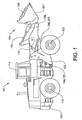
- Figure 1 shows a frame-steered work machine constituting a wheel loader 101.
- the body of the wheel loader 101 comprises a front body section 102 and a rear body section 103, which sections each has an axle 112,113 for driving a pair of wheels.
- the rear body section 103 comprises a cab 114.
- the body sections 102, 103 are connected to each other in such a way that they can pivot in relation to each other around a vertical axis by means of two first actuators in the form of hydraulic cylinders 104, 105 arranged between the two sections.
- the hydraulic cylinders 104,105 are thus arranged one on each side of a horizontal centerline of the vehicle in a vehicle traveling direction in order to turn the wheel loader 101.
- the wheel loader 101 comprises an equipment 111 for handling an external load, such as objects or material.
- the equipment 111 comprises a load-arm unit 106 and an implement 107 in the form of a bucket fitted on the load-arm unit.
- a first end of the load-arm unit 106 is pivotally connected to the front vehicle section 102.
- the bucket 107 is pivotally connected to a second end of the load-arm unit 106.
- the load-arm unit 106 can be raised and lowered relative to the front section 102 of the vehicle by means of two second actuators in the form of two hydraulic cylinders 108, 109, each of which is connected at one end to the front vehicle section 102 and at the other end to the load-arm unit 106.
- the bucket 107 can be tilted relative to the load-arm unit 106 by means of a third actuator in the form of a hydraulic cylinder 110, which is connected at one end to the front vehicle section 102 and at the other end to the bucket 107 via a link-arm system 115.
- FIG 2 shows a first embodiment of a wheel hub unit 201 in a diagrammatic, partly cut side view.
- the wheel hub unit 201 is arranged at one end of an axle case 203 of a wheel axle 205.
- a drive shaft 207 extends inside the axle case 203 in a transverse direction of the work machine.
- the drive shaft 207 is, at one 209 of its ends, provided with a hub reduction gear 211 in the form of a planetary gear transmission.
- the drive shaft 207 is operationally connected to a central gear (not shown) which in turn is driven by the power unit of the vehicle via a gearbox and a drive shaft extending in a longitudinal direction of the work machine.
- the planetary gear transmission 211 comprises a sun gear 213, which is rotationally rigidly connected to the drive shaft 207. Thus, the sun gear 213 forms an input to the reduction gear.
- the planetary gear transmission 211 further comprises a number of circumferentially spaced planet gears 215 in driving interconnection with the sun gear and with a ring gear 217 via teeth.
- the planetary gear transmission 211 is of a type with a stationary ring gear.
- each of the planet gears 215 is journalled on an axially extending shaft pivot 219.
- the number of planet gears 215 can be one, two, three, four or more.
- the planet carrier 221 forms an output from the reduction gear.
- a brake 223 consisting of a wet brake is adapted to brake the drive shaft 207.
- the brake 223 is arranged between the reduction gear 211 and the central gear (not shown) in the axle.
- the brake comprises a single brake rotor 225.
- the sun gear 213 has guide surfaces, in the form of a number of parallel ridges, or teeth, for engagement with and guidance in the axial direction of the brake rotor 225 when the brake 223 is activated.
- the connection consists of a spline joint 250.
- the brake rotor 225 is connected to the sun gear 213 and therefore to the drive shaft 207 in a rotationally fixed manner and is displaceable in the axial direction on said spline joint 250.
- the single brake rotor 225 is arranged between a pair of brake pads 237,239.
- the brake further comprises a hydraulically operated device 240 for actuating the brake by clamping the brake rotor 225.
- the brake device 240 comprises a brake piston 241 for applying the brake by pressing the brake rotor between the brake pads 237,239 and thus increasing the friction force between them.
- one of the brake pads 239 is moveable by means of the brake piston 241 and the other brake pad 237 on an opposite side of the brake rotor relative to the brake piston forms a pressure surface, or stay, against which the brake rotor is brought when the brake is applied.
- the drive shaft 207 is braked directly.
- the drive shaft 207 usually has a speed which is approximately six times higher than that of the wheel.
- a wheel hub 242 is connected firmly to the planet carrier 221. More specifically, the wheel hub 242 is rotationally rigidly connected to the planet carrier 221 via a splined connection 246. The wheel is fastened by a conventional fastening device on the hub, usually a bolt joint 244.
- the brake rotor 225 is shown in more detail in figures 3-4 .
- the brake rotor 225 comprises a pair of brake force transmitting discs 227,229 and a damping layer 231 positioned between the discs 227,229 and secured to each of the discs.
- the brake force transmitting discs 227,229 are preferably of metallic material.
- the damping layer is configured for absorbing energy in order to provide the brake with a soft actuation.
- the damping layer comprises a cork material.
- the damping layer may comprise other materials, such as organic material and/or polymeric material.
- Each of the brake force transmitting discs 227,229 is configured for a rotationally rigid connection to a the drive shaft 207.
- each of the brake force transmitting discs 227,229 comprises a central hole 248 with a cross sectional pattern complimentary to the outer pattern of the sun gear 213 for engagement therewith.
- the brake force transmitting discs 227,229 are connected to the drive shaft 207 via the splined connection 250, see figure 2 .
- the brake rotor 225 comprises a layer 233,235 of friction material on an outer side of each of the brake force transmitting discs 227,229.
- the brake pads 237,239 are disposed adjacent each friction layer 233,235 such that a smooth surface of the pads is forced against the friction surfaces of the brake rotor.
- the brake rotor 225 comprises a plurality of circumferentially spaced elongated openings 303 extending in a radial direction of the brake rotor.
- the opening configuration is configured for providing the brake rotor with a pumping effect for transporting a coolant during rotation in order to cool the brake rotor.
- the elongated openings 303 extend through the brake rotor in an axial direction and are open radially outwards.
- the friction layer 233 is provided with a groove pattern 305 adapted to transport coolant during operation. More specifically, the pattern 305 comprises a channel configuration comprises a plurality of straight channels 307 extending over the friction layer.
- the straight channels have a substantially radial direction. More specifically, the straight channels 307 are arranged in parallel with each other in each sector of the brake rotor 225 between two adjacent openings 303.
- the channel configuration contributes to said pumping effect.
- the invention is not limited to a brake with a single brake rotor.
- the brake may be provided with a plurality of brake rotors of the design described above.
Abstract
Description
- The present invention relates to a brake for a work machine, wherein the brake comprises a brake rotor, a hydraulically operated device for actuating the brake by clamping the brake rotor, and means for damping jerks resulting from a sudden brake actuation. The invention further relates to a wheel hub unit comprising the brake and a work machine comprising the wheel hub unit.
- The invention can be applied in vehicles or work machines which are intended to be driven on a relatively flat surface, such as a road, and/or on uneven ground off road. The invention is especially applicable for a relatively slow moving work machine, such as a wheel loader. By the term "relatively slow moving" is meant a vehicle/work machine with a maximum speed of about 50 km/h.
- A wheel loader must be equipped with brakes that are suited for the varying characteristics of the machine. In one extreme case, a fully loaded machine must be powerfully retarded and in another extreme case the same machine without any load must be gently braked. In order to enable the driver of the machine to handle the machine, the retardation must feel controllable and manageable under all conditions.
- According to a known solution, wet brakes are arranged at each wheel. More specifically, a reduction gear in the form of a planetary gear is operatively connected between an end of a drive shaft extending from a central gear (differential gear) in an axle and a wheel hub. The planetary gear is adapted for a downshift of rotational speed from the drive shaft to the wheel hub. The wet brake is arranged for braking the drive shaft. Especially, a brake rotor is rotationally rigidly connected to the drive shaft. A moveable piston is operatively connected to brake pads for clamping a brake rotor between the brake pads for brake actuation. The piston is moved under the pressure of a hydraulic oil.
- When the brake is actuated (initiated via depression of a brake pedal) it takes a certain time to move the brake piston from an initial position to the position when the brake pads are in contact with the brake rotor. Once the brake piston has reached the latter position, the pressurization of the hydraulic oil against the brake piston commences, which leads to a powerful excess pressure surge in the form of a pressure pulse in the hydraulic oil. This excess pressure surge gives rise to a brake shock (a powerful retardation of the machine), which the driver experiences as a jerk. Such a jerk results in that the driver is exposed to vibrations. The excess pressure surge also results in that the components of the brake being exposed to heavy stresses, which among other things generates noise. The noise is experienced by the driver and persons near the machine as an irritation.
-
US-A-5 035 305 discloses a brake having cushioning means to dampen reaction forces between the brake assembly components. - According to a known solution to said problem of jerks in the actuation phase of the brake, the hydraulic circuit is provided with damping means in the form of an accumulator for accumulating the excess energy in the hydraulic oil.
- One object of the invention is to provide a hydraulically operated wet brake which is adapted to at least reduce the jerks resulting from brake actuation and which creates conditions for a more cost-efficient brake system. Further, the brake should provide good controllability.
- This object is achieved by means of the brake according to claim 1. Thus, the object is achieved in that the brake rotor comprises a pair of brake force transmitting discs and that the damping means is formed by a damping layer positioned between the brake force transmitting discs and secured to each of the discs.
- The brake rotor design reduces the sensitivity of the brake at the initiation in that the damping layer is adapted to absorb energy. In other words, the damping layer functions as a cushioning means.
- A secondary effect is that the noise from the actuation of the brake is eliminated.
- The brake force transmitting discs are configured for a rotationally rigid connection with a drive member (preferably a drive shaft). Due to the fact that the damping layer is interposed between the discs, the brake function is preserved even if the damping layer and/or the attachment of the damping layer to the metallic discs is damaged.
- Accordingly, the inventive design of the brake creates conditions for eliminating the accumulator in the hydraulic system according to prior art.
- According to a preferred embodiment of the invention, the damping layer comprises cork material.
- Further preferred embodiments and advantages of these emerge from the description below and from the claims.
- The invention will be described in greater detail below with reference to the embodiments shown in the accompanying drawings, in which
- FIG. 1
- shows side view of a wheel loader,
- FIG. 2
- shows a diagrammatic, partly cut side view of a wheel hub unit of the wheel loader according to a first embodiment,
- FIG. 3
- shows a cross sectional view of a brake rotor in a brake provided in the wheel hub unit in
figure 2 , and - FIG. 4
- is a side view of the brake rotor in
figure 3 . -
Figure 1 shows a frame-steered work machine constituting awheel loader 101. The body of thewheel loader 101 comprises afront body section 102 and arear body section 103, which sections each has an axle 112,113 for driving a pair of wheels. Therear body section 103 comprises acab 114. Thebody sections wheel loader 101. - The
wheel loader 101 comprises anequipment 111 for handling an external load, such as objects or material. Theequipment 111 comprises a load-arm unit 106 and animplement 107 in the form of a bucket fitted on the load-arm unit. A first end of the load-arm unit 106 is pivotally connected to thefront vehicle section 102. Thebucket 107 is pivotally connected to a second end of the load-arm unit 106. - The load-
arm unit 106 can be raised and lowered relative to thefront section 102 of the vehicle by means of two second actuators in the form of two hydraulic cylinders 108, 109, each of which is connected at one end to thefront vehicle section 102 and at the other end to the load-arm unit 106. Thebucket 107 can be tilted relative to the load-arm unit 106 by means of a third actuator in the form of ahydraulic cylinder 110, which is connected at one end to thefront vehicle section 102 and at the other end to thebucket 107 via a link-arm system 115. -
Figure 2 shows a first embodiment of awheel hub unit 201 in a diagrammatic, partly cut side view. Thewheel hub unit 201 is arranged at one end of an axle case 203 of awheel axle 205. A drive shaft 207 extends inside the axle case 203 in a transverse direction of the work machine. The drive shaft 207 is, at one 209 of its ends, provided with ahub reduction gear 211 in the form of a planetary gear transmission. At its other end, the drive shaft 207 is operationally connected to a central gear (not shown) which in turn is driven by the power unit of the vehicle via a gearbox and a drive shaft extending in a longitudinal direction of the work machine. - The
planetary gear transmission 211 comprises asun gear 213, which is rotationally rigidly connected to the drive shaft 207. Thus, thesun gear 213 forms an input to the reduction gear. Theplanetary gear transmission 211 further comprises a number of circumferentially spaced planet gears 215 in driving interconnection with the sun gear and with aring gear 217 via teeth. Theplanetary gear transmission 211 is of a type with a stationary ring gear. - A
planet carrier 221, also known as a planet gear holder, is adapted so as to hold the planet gears 215. To be precise, each of the planet gears 215 is journalled on an axially extendingshaft pivot 219. The number of planet gears 215 can be one, two, three, four or more. Theplanet carrier 221 forms an output from the reduction gear. - A
brake 223 consisting of a wet brake is adapted to brake the drive shaft 207. Thus, thebrake 223 is arranged between thereduction gear 211 and the central gear (not shown) in the axle. The brake comprises asingle brake rotor 225. Thesun gear 213 has guide surfaces, in the form of a number of parallel ridges, or teeth, for engagement with and guidance in the axial direction of thebrake rotor 225 when thebrake 223 is activated. The connection consists of a spline joint 250. Thus, thebrake rotor 225 is connected to thesun gear 213 and therefore to the drive shaft 207 in a rotationally fixed manner and is displaceable in the axial direction on said spline joint 250. - The
single brake rotor 225 is arranged between a pair of brake pads 237,239. The brake further comprises a hydraulically operateddevice 240 for actuating the brake by clamping thebrake rotor 225. Thebrake device 240 comprises abrake piston 241 for applying the brake by pressing the brake rotor between the brake pads 237,239 and thus increasing the friction force between them. Thus, one of thebrake pads 239 is moveable by means of thebrake piston 241 and theother brake pad 237 on an opposite side of the brake rotor relative to the brake piston forms a pressure surface, or stay, against which the brake rotor is brought when the brake is applied. - By means of this type of brake, the drive shaft 207 is braked directly. The drive shaft 207 usually has a speed which is approximately six times higher than that of the wheel.
- A
wheel hub 242 is connected firmly to theplanet carrier 221. More specifically, thewheel hub 242 is rotationally rigidly connected to theplanet carrier 221 via asplined connection 246. The wheel is fastened by a conventional fastening device on the hub, usually abolt joint 244. - The
brake rotor 225 is shown in more detail infigures 3-4 . Thebrake rotor 225 comprises a pair of brake force transmitting discs 227,229 and a dampinglayer 231 positioned between the discs 227,229 and secured to each of the discs. The brake force transmitting discs 227,229 are preferably of metallic material. The damping layer is configured for absorbing energy in order to provide the brake with a soft actuation. Preferably, the damping layer comprises a cork material. However, according to an alternative, complement, the damping layer may comprise other materials, such as organic material and/or polymeric material. Each of the brake force transmitting discs 227,229 is configured for a rotationally rigid connection to a the drive shaft 207. More specifically, each of the brake force transmitting discs 227,229 comprises acentral hole 248 with a cross sectional pattern complimentary to the outer pattern of thesun gear 213 for engagement therewith. The brake force transmitting discs 227,229 are connected to the drive shaft 207 via thesplined connection 250, seefigure 2 . - Further, the
brake rotor 225 comprises a layer 233,235 of friction material on an outer side of each of the brake force transmitting discs 227,229. Thus, the brake pads 237,239 are disposed adjacent each friction layer 233,235 such that a smooth surface of the pads is forced against the friction surfaces of the brake rotor. - Turning now to
figure 4 , thebrake rotor 225 comprises a plurality of circumferentially spacedelongated openings 303 extending in a radial direction of the brake rotor. The opening configuration is configured for providing the brake rotor with a pumping effect for transporting a coolant during rotation in order to cool the brake rotor. Theelongated openings 303 extend through the brake rotor in an axial direction and are open radially outwards. Thefriction layer 233 is provided with agroove pattern 305 adapted to transport coolant during operation. More specifically, thepattern 305 comprises a channel configuration comprises a plurality ofstraight channels 307 extending over the friction layer. The straight channels have a substantially radial direction. More specifically, thestraight channels 307 are arranged in parallel with each other in each sector of thebrake rotor 225 between twoadjacent openings 303. The channel configuration contributes to said pumping effect. - The invention is not to be regarded as being limited to the illustrative embodiments described above, but a number of further variants and modifications are conceivable within the scope of the patent claims which follow. For example, the application may differ, or the power unit of the vehicle may be arranged so as to drive the drive shaft 207 directly, that is to say without an intermediate drive shaft and central gear.
- Further, the invention is not limited to a brake with a single brake rotor. Thus, the brake may be provided with a plurality of brake rotors of the design described above.
Claims (11)
- A wet brake (223) for a work machine (101), wherein the brake (223) comprises a brake rotor (225), a hydraulically operated device (240) for actuating the brake by clamping the brake rotor (225), and means for damping jerks resulting from a sudden brake actuation, characterized in that the brake rotor (225) comprises a pair of brake force transmitting discs (227,229) and that the damping means is formed by a damping layer (231) positioned between the discs and secured to each of the discs.
- A wet brake according to claim 1, characterized in that the damping layer (231) is configured for absorbing energy.
- A wet brake according to claim 1 or 2, characterized in that the damping layer (231) comprises cork material.
- A wet brake according to any preceding claim, characterized in that each of the brake force transmitting discs (227,229) is configured for a rotationally rigid connection to a drive member (207).
- A wet brake according to any preceding claim, characterized in that the brake rotor (225) comprises a layer (233,235) of friction material on an outer side of each of the brake force transmitting discs (227,229).
- A wet brake according to any preceding claim, characterized in that the brake comprises a single brake rotor (225) arranged between a pair of brake pads (237,239).
- A wet brake according to claim 6, characterized in that the brake actuation device (240) comprises a moveable piston (241) operatively connected to the brake pads (237,239) for clamping the brake rotor between the brake pads for brake actuation.
- A wheel hub unit (201) for a work machine comprising a drive shaft adapted to transmit power to a wheel hub characterized in that the wheel hub unit (201) comprises the wet brake (223) according to any preceding claim, and that the brake rotor (225) is rotationally rigidly connected to the drive shaft.
- A wheel hub unit according to claim 8 characterized in that the wheel hub unit comprises a reduction gear (211) operatively connected to an end of the drive shaft (207) and to the wheel hub and that the reduction gear is adapted for a downshift of rotational speed from the drive shaft to the wheel hub.
- A wheel hub unit according to claim 9 characterized in that the reduction gear (211) comprises a planetary gear.
- A work machine characterized in that it comprises a wheel hub unit according to any one of claims 8-10.
Applications Claiming Priority (1)
| Application Number | Priority Date | Filing Date | Title |
|---|---|---|---|
| PCT/SE2008/000253 WO2009126067A1 (en) | 2008-04-08 | 2008-04-08 | A brake for a work machine, a wheel hub unit and a work machine |
Publications (3)
| Publication Number | Publication Date |
|---|---|
| EP2274533A1 EP2274533A1 (en) | 2011-01-19 |
| EP2274533A4 EP2274533A4 (en) | 2011-09-07 |
| EP2274533B1 true EP2274533B1 (en) | 2012-08-08 |
Family
ID=41162071
Family Applications (1)
| Application Number | Title | Priority Date | Filing Date |
|---|---|---|---|
| EP08724168A Not-in-force EP2274533B1 (en) | 2008-04-08 | 2008-04-08 | A brake for a work machine, a wheel hub unit and a work machine |
Country Status (4)
| Country | Link |
|---|---|
| US (1) | US20110005873A1 (en) |
| EP (1) | EP2274533B1 (en) |
| CN (1) | CN101983295B (en) |
| WO (1) | WO2009126067A1 (en) |
Families Citing this family (2)
| Publication number | Priority date | Publication date | Assignee | Title |
|---|---|---|---|---|
| DE102013226333A1 (en) * | 2013-12-18 | 2015-06-18 | Volkswagen Aktiengesellschaft | Brake disk ring with cooling channels arranged therein |
| DE102019000312A1 (en) | 2018-02-02 | 2019-08-08 | Sew-Eurodrive Gmbh & Co Kg | Carrier disk assembly for brake assembly and electromagnetically actuated brake assembly with carrier disk assembly |
Family Cites Families (25)
| Publication number | Priority date | Publication date | Assignee | Title |
|---|---|---|---|---|
| US2163884A (en) * | 1936-07-06 | 1939-06-27 | Bendix Prod Corp | Brake |
| US3231058A (en) * | 1962-02-19 | 1966-01-25 | Raybestos Manhattan Inc | Friction device |
| GB1235168A (en) * | 1967-09-27 | 1971-06-09 | Frankl & Kirchner | Improvements relating to electromagnetic clutches or brakes |
| US4072219A (en) * | 1974-12-07 | 1978-02-07 | Itt Industries, Incorporated | Multi-part disc brake |
| US4022298A (en) * | 1976-03-29 | 1977-05-10 | D.A.B. Industries, Inc. | Wet disc brake |
| US4529079A (en) * | 1980-01-16 | 1985-07-16 | Borg-Warner Corporation | Cushion-bonded driven disc assembly and method of construction |
| JPS5872735A (en) * | 1981-10-22 | 1983-04-30 | Akebono Brake Ind Co Ltd | Disc brake rotor |
| JPS58149431A (en) * | 1982-02-26 | 1983-09-05 | Mitsubishi Electric Corp | Movable plate of electromagnetic clutch brake |
| US4585096A (en) * | 1984-08-03 | 1986-04-29 | The B. F. Goodrich Company | Brake apparatus |
| US5035305A (en) * | 1989-10-02 | 1991-07-30 | Caterpillar Inc. | Cushioned brake assembly |
| US5035205A (en) * | 1990-02-23 | 1991-07-30 | Philip Schiller | Collapsible disposable cat litter box |
| SE506828C2 (en) * | 1996-06-13 | 1998-02-16 | Volvo Wheel Loaders Ab | Mechanically adjustable wear indicator |
| US5878843A (en) * | 1997-09-24 | 1999-03-09 | Hayes Lemmerz International, Inc. | Laminated brake rotor |
| JPH11101266A (en) * | 1997-09-30 | 1999-04-13 | Exedy Corp | Friction coupling member and clutch disc assembly |
| EP0978665B1 (en) * | 1998-08-05 | 2004-06-09 | Freni Brembo S.p.A. | Device for indicating lining wear in floating caliper disc brakes |
| US6241055B1 (en) * | 1998-09-11 | 2001-06-05 | Hayes Lemmerz International, Inc. | Rotor with viscoelastic vibration reducing element and method of making the same |
| AU2001218432A1 (en) * | 2000-08-01 | 2002-02-13 | Safe Effect Technologies International Limited | Wet brake system |
| US6702076B2 (en) * | 2001-01-16 | 2004-03-09 | Michael T. Koleda | Shaft vibration damping system |
| US6752248B2 (en) * | 2001-09-04 | 2004-06-22 | Honeywell International Inc. | Multi-disc brake structural asymmetry |
| US8245758B2 (en) * | 2006-10-30 | 2012-08-21 | GM Global Technology Operations LLC | Coulomb damped disc brake rotor and method of manufacturing |
| ATE390576T1 (en) * | 2004-12-14 | 2008-04-15 | Volvo Constr Equip Holding Se | ARRANGEMENT FOR REDUCING A ROTATIONAL SPEED OF A ROTATING LIMB |
| DE102005006298A1 (en) * | 2005-02-11 | 2006-08-24 | Audi Ag | Multi-disc brake for vehicles, in particular double disc brake for motor vehicles |
| WO2007126348A1 (en) * | 2006-04-28 | 2007-11-08 | Volvo Construction Equipment Ab | A wheel brake for a vehicle and a vehicle comprising the wheel brake |
| US7938378B2 (en) * | 2007-08-01 | 2011-05-10 | GM Global Technology Operations LLC | Damped product with insert and method of making the same |
| US8118079B2 (en) * | 2007-08-17 | 2012-02-21 | GM Global Technology Operations LLC | Casting noise-damped, vented brake rotors with embedded inserts |
-
2008
- 2008-04-08 CN CN2008801284751A patent/CN101983295B/en not_active Expired - Fee Related
- 2008-04-08 US US12/922,701 patent/US20110005873A1/en not_active Abandoned
- 2008-04-08 EP EP08724168A patent/EP2274533B1/en not_active Not-in-force
- 2008-04-08 WO PCT/SE2008/000253 patent/WO2009126067A1/en active Application Filing
Also Published As
| Publication number | Publication date |
|---|---|
| CN101983295B (en) | 2013-05-22 |
| WO2009126067A1 (en) | 2009-10-15 |
| EP2274533A4 (en) | 2011-09-07 |
| EP2274533A1 (en) | 2011-01-19 |
| US20110005873A1 (en) | 2011-01-13 |
| CN101983295A (en) | 2011-03-02 |
Similar Documents
| Publication | Publication Date | Title |
|---|---|---|
| EP1354747B1 (en) | Vehicle, dumper or wheel loader or excavator comprising a planetary transmission | |
| US7485061B2 (en) | Drive train of hybrid vehicle | |
| US6135259A (en) | Hub drive | |
| KR100425277B1 (en) | Wheel transmission | |
| US11358579B2 (en) | Electrohydraulic brake actuator | |
| CN114585835B (en) | Transmission assembly | |
| EP2274533B1 (en) | A brake for a work machine, a wheel hub unit and a work machine | |
| EP1910121B1 (en) | Planet transmission, drive device comprising the planet transmission and vehicle comprising the drive device | |
| US4407399A (en) | Two-speed transmission with hydraulic actuation of the shifting operations under load | |
| CN1813142B (en) | Brake assembly, particularly for a hydraulic wheel drive | |
| EP1899619B1 (en) | Planetary transmission, drive device and work vehicle | |
| US6536560B1 (en) | Single braking assembly for a drive axle | |
| KR102605780B1 (en) | Power transmission device for vehicle | |
| US11807199B2 (en) | Portal braking system | |
| JP6478865B2 (en) | Reverse load prevention mechanism for vehicle transmission | |
| KR100568033B1 (en) | vehicle Multi Shifting Transwheel | |
| CN114435123A (en) | Electric vehicle wheel end assembly | |
| RU2462371C2 (en) | Off-road car transmission | |
| AU762590B2 (en) | Planetary transmission for a vehicle | |
| JPH11303990A (en) | Brake device of crawler vehicle |
Legal Events
| Date | Code | Title | Description |
|---|---|---|---|
| PUAI | Public reference made under article 153(3) epc to a published international application that has entered the european phase |
Free format text: ORIGINAL CODE: 0009012 |
|
| 17P | Request for examination filed |
Effective date: 20101108 |
|
| AK | Designated contracting states |
Kind code of ref document: A1 Designated state(s): AT BE BG CH CY CZ DE DK EE ES FI FR GB GR HR HU IE IS IT LI LT LU LV MC MT NL NO PL PT RO SE SI SK TR |
|
| AX | Request for extension of the european patent |
Extension state: AL BA MK RS |
|
| DAX | Request for extension of the european patent (deleted) | ||
| A4 | Supplementary search report drawn up and despatched |
Effective date: 20110810 |
|
| RIC1 | Information provided on ipc code assigned before grant |
Ipc: F16D 65/12 20060101AFI20110804BHEP |
|
| GRAP | Despatch of communication of intention to grant a patent |
Free format text: ORIGINAL CODE: EPIDOSNIGR1 |
|
| GRAS | Grant fee paid |
Free format text: ORIGINAL CODE: EPIDOSNIGR3 |
|
| GRAA | (expected) grant |
Free format text: ORIGINAL CODE: 0009210 |
|
| AK | Designated contracting states |
Kind code of ref document: B1 Designated state(s): AT BE BG CH CY CZ DE DK EE ES FI FR GB GR HR HU IE IS IT LI LT LU LV MC MT NL NO PL PT RO SE SI SK TR |
|
| REG | Reference to a national code |
Ref country code: GB Ref legal event code: FG4D |
|
| REG | Reference to a national code |
Ref country code: CH Ref legal event code: EP Ref country code: AT Ref legal event code: REF Ref document number: 569943 Country of ref document: AT Kind code of ref document: T Effective date: 20120815 |
|
| REG | Reference to a national code |
Ref country code: IE Ref legal event code: FG4D |
|
| REG | Reference to a national code |
Ref country code: DE Ref legal event code: R096 Ref document number: 602008017799 Country of ref document: DE Effective date: 20121004 |
|
| REG | Reference to a national code |
Ref country code: NL Ref legal event code: VDEP Effective date: 20120808 |
|
| REG | Reference to a national code |
Ref country code: AT Ref legal event code: MK05 Ref document number: 569943 Country of ref document: AT Kind code of ref document: T Effective date: 20120808 |
|
| REG | Reference to a national code |
Ref country code: LT Ref legal event code: MG4D Effective date: 20120808 |
|
| PG25 | Lapsed in a contracting state [announced via postgrant information from national office to epo] |
Ref country code: CY Free format text: LAPSE BECAUSE OF FAILURE TO SUBMIT A TRANSLATION OF THE DESCRIPTION OR TO PAY THE FEE WITHIN THE PRESCRIBED TIME-LIMIT Effective date: 20120808 Ref country code: AT Free format text: LAPSE BECAUSE OF FAILURE TO SUBMIT A TRANSLATION OF THE DESCRIPTION OR TO PAY THE FEE WITHIN THE PRESCRIBED TIME-LIMIT Effective date: 20120808 Ref country code: NO Free format text: LAPSE BECAUSE OF FAILURE TO SUBMIT A TRANSLATION OF THE DESCRIPTION OR TO PAY THE FEE WITHIN THE PRESCRIBED TIME-LIMIT Effective date: 20121108 Ref country code: IS Free format text: LAPSE BECAUSE OF FAILURE TO SUBMIT A TRANSLATION OF THE DESCRIPTION OR TO PAY THE FEE WITHIN THE PRESCRIBED TIME-LIMIT Effective date: 20121208 Ref country code: FI Free format text: LAPSE BECAUSE OF FAILURE TO SUBMIT A TRANSLATION OF THE DESCRIPTION OR TO PAY THE FEE WITHIN THE PRESCRIBED TIME-LIMIT Effective date: 20120808 Ref country code: HR Free format text: LAPSE BECAUSE OF FAILURE TO SUBMIT A TRANSLATION OF THE DESCRIPTION OR TO PAY THE FEE WITHIN THE PRESCRIBED TIME-LIMIT Effective date: 20120808 Ref country code: LT Free format text: LAPSE BECAUSE OF FAILURE TO SUBMIT A TRANSLATION OF THE DESCRIPTION OR TO PAY THE FEE WITHIN THE PRESCRIBED TIME-LIMIT Effective date: 20120808 |
|
| PG25 | Lapsed in a contracting state [announced via postgrant information from national office to epo] |
Ref country code: SI Free format text: LAPSE BECAUSE OF FAILURE TO SUBMIT A TRANSLATION OF THE DESCRIPTION OR TO PAY THE FEE WITHIN THE PRESCRIBED TIME-LIMIT Effective date: 20120808 Ref country code: BE Free format text: LAPSE BECAUSE OF FAILURE TO SUBMIT A TRANSLATION OF THE DESCRIPTION OR TO PAY THE FEE WITHIN THE PRESCRIBED TIME-LIMIT Effective date: 20120808 Ref country code: LV Free format text: LAPSE BECAUSE OF FAILURE TO SUBMIT A TRANSLATION OF THE DESCRIPTION OR TO PAY THE FEE WITHIN THE PRESCRIBED TIME-LIMIT Effective date: 20120808 Ref country code: PL Free format text: LAPSE BECAUSE OF FAILURE TO SUBMIT A TRANSLATION OF THE DESCRIPTION OR TO PAY THE FEE WITHIN THE PRESCRIBED TIME-LIMIT Effective date: 20120808 Ref country code: PT Free format text: LAPSE BECAUSE OF FAILURE TO SUBMIT A TRANSLATION OF THE DESCRIPTION OR TO PAY THE FEE WITHIN THE PRESCRIBED TIME-LIMIT Effective date: 20121210 Ref country code: GR Free format text: LAPSE BECAUSE OF FAILURE TO SUBMIT A TRANSLATION OF THE DESCRIPTION OR TO PAY THE FEE WITHIN THE PRESCRIBED TIME-LIMIT Effective date: 20121109 Ref country code: SE Free format text: LAPSE BECAUSE OF FAILURE TO SUBMIT A TRANSLATION OF THE DESCRIPTION OR TO PAY THE FEE WITHIN THE PRESCRIBED TIME-LIMIT Effective date: 20120808 |
|
| PG25 | Lapsed in a contracting state [announced via postgrant information from national office to epo] |
Ref country code: NL Free format text: LAPSE BECAUSE OF FAILURE TO SUBMIT A TRANSLATION OF THE DESCRIPTION OR TO PAY THE FEE WITHIN THE PRESCRIBED TIME-LIMIT Effective date: 20120808 |
|
| PG25 | Lapsed in a contracting state [announced via postgrant information from national office to epo] |
Ref country code: DK Free format text: LAPSE BECAUSE OF FAILURE TO SUBMIT A TRANSLATION OF THE DESCRIPTION OR TO PAY THE FEE WITHIN THE PRESCRIBED TIME-LIMIT Effective date: 20120808 Ref country code: ES Free format text: LAPSE BECAUSE OF FAILURE TO SUBMIT A TRANSLATION OF THE DESCRIPTION OR TO PAY THE FEE WITHIN THE PRESCRIBED TIME-LIMIT Effective date: 20121119 Ref country code: CZ Free format text: LAPSE BECAUSE OF FAILURE TO SUBMIT A TRANSLATION OF THE DESCRIPTION OR TO PAY THE FEE WITHIN THE PRESCRIBED TIME-LIMIT Effective date: 20120808 Ref country code: EE Free format text: LAPSE BECAUSE OF FAILURE TO SUBMIT A TRANSLATION OF THE DESCRIPTION OR TO PAY THE FEE WITHIN THE PRESCRIBED TIME-LIMIT Effective date: 20120808 Ref country code: RO Free format text: LAPSE BECAUSE OF FAILURE TO SUBMIT A TRANSLATION OF THE DESCRIPTION OR TO PAY THE FEE WITHIN THE PRESCRIBED TIME-LIMIT Effective date: 20120808 |
|
| PG25 | Lapsed in a contracting state [announced via postgrant information from national office to epo] |
Ref country code: SK Free format text: LAPSE BECAUSE OF FAILURE TO SUBMIT A TRANSLATION OF THE DESCRIPTION OR TO PAY THE FEE WITHIN THE PRESCRIBED TIME-LIMIT Effective date: 20120808 Ref country code: IT Free format text: LAPSE BECAUSE OF FAILURE TO SUBMIT A TRANSLATION OF THE DESCRIPTION OR TO PAY THE FEE WITHIN THE PRESCRIBED TIME-LIMIT Effective date: 20120808 |
|
| PLBE | No opposition filed within time limit |
Free format text: ORIGINAL CODE: 0009261 |
|
| STAA | Information on the status of an ep patent application or granted ep patent |
Free format text: STATUS: NO OPPOSITION FILED WITHIN TIME LIMIT |
|
| 26N | No opposition filed |
Effective date: 20130510 |
|
| PG25 | Lapsed in a contracting state [announced via postgrant information from national office to epo] |
Ref country code: BG Free format text: LAPSE BECAUSE OF FAILURE TO SUBMIT A TRANSLATION OF THE DESCRIPTION OR TO PAY THE FEE WITHIN THE PRESCRIBED TIME-LIMIT Effective date: 20121108 |
|
| REG | Reference to a national code |
Ref country code: DE Ref legal event code: R097 Ref document number: 602008017799 Country of ref document: DE Effective date: 20130510 |
|
| PG25 | Lapsed in a contracting state [announced via postgrant information from national office to epo] |
Ref country code: MC Free format text: LAPSE BECAUSE OF FAILURE TO SUBMIT A TRANSLATION OF THE DESCRIPTION OR TO PAY THE FEE WITHIN THE PRESCRIBED TIME-LIMIT Effective date: 20120808 |
|
| REG | Reference to a national code |
Ref country code: CH Ref legal event code: PL |
|
| REG | Reference to a national code |
Ref country code: IE Ref legal event code: MM4A |
|
| PG25 | Lapsed in a contracting state [announced via postgrant information from national office to epo] |
Ref country code: CH Free format text: LAPSE BECAUSE OF NON-PAYMENT OF DUE FEES Effective date: 20130430 Ref country code: LI Free format text: LAPSE BECAUSE OF NON-PAYMENT OF DUE FEES Effective date: 20130430 |
|
| REG | Reference to a national code |
Ref country code: FR Ref legal event code: ST Effective date: 20131231 |
|
| PG25 | Lapsed in a contracting state [announced via postgrant information from national office to epo] |
Ref country code: FR Free format text: LAPSE BECAUSE OF NON-PAYMENT OF DUE FEES Effective date: 20130430 |
|
| PG25 | Lapsed in a contracting state [announced via postgrant information from national office to epo] |
Ref country code: IE Free format text: LAPSE BECAUSE OF NON-PAYMENT OF DUE FEES Effective date: 20130408 |
|
| PG25 | Lapsed in a contracting state [announced via postgrant information from national office to epo] |
Ref country code: MT Free format text: LAPSE BECAUSE OF FAILURE TO SUBMIT A TRANSLATION OF THE DESCRIPTION OR TO PAY THE FEE WITHIN THE PRESCRIBED TIME-LIMIT Effective date: 20120808 |
|
| PG25 | Lapsed in a contracting state [announced via postgrant information from national office to epo] |
Ref country code: TR Free format text: LAPSE BECAUSE OF FAILURE TO SUBMIT A TRANSLATION OF THE DESCRIPTION OR TO PAY THE FEE WITHIN THE PRESCRIBED TIME-LIMIT Effective date: 20120808 |
|
| PG25 | Lapsed in a contracting state [announced via postgrant information from national office to epo] |
Ref country code: LU Free format text: LAPSE BECAUSE OF NON-PAYMENT OF DUE FEES Effective date: 20130408 Ref country code: HU Free format text: LAPSE BECAUSE OF FAILURE TO SUBMIT A TRANSLATION OF THE DESCRIPTION OR TO PAY THE FEE WITHIN THE PRESCRIBED TIME-LIMIT; INVALID AB INITIO Effective date: 20080408 |
|
| PGFP | Annual fee paid to national office [announced via postgrant information from national office to epo] |
Ref country code: GB Payment date: 20220419 Year of fee payment: 15 Ref country code: DE Payment date: 20220428 Year of fee payment: 15 |
|
| REG | Reference to a national code |
Ref country code: DE Ref legal event code: R119 Ref document number: 602008017799 Country of ref document: DE |
|
| GBPC | Gb: european patent ceased through non-payment of renewal fee |
Effective date: 20230408 |
|
| PG25 | Lapsed in a contracting state [announced via postgrant information from national office to epo] |
Ref country code: GB Free format text: LAPSE BECAUSE OF NON-PAYMENT OF DUE FEES Effective date: 20230408 |
|
| PG25 | Lapsed in a contracting state [announced via postgrant information from national office to epo] |
Ref country code: GB Free format text: LAPSE BECAUSE OF NON-PAYMENT OF DUE FEES Effective date: 20230408 Ref country code: DE Free format text: LAPSE BECAUSE OF NON-PAYMENT OF DUE FEES Effective date: 20231103 |