EP2274113B1 - Method and apparatus for controlled cooling - Google Patents
Method and apparatus for controlled cooling Download PDFInfo
- Publication number
- EP2274113B1 EP2274113B1 EP09730976.9A EP09730976A EP2274113B1 EP 2274113 B1 EP2274113 B1 EP 2274113B1 EP 09730976 A EP09730976 A EP 09730976A EP 2274113 B1 EP2274113 B1 EP 2274113B1
- Authority
- EP
- European Patent Office
- Prior art keywords
- cooling
- zone separation
- flow
- spray devices
- flow out
- Prior art date
- Legal status (The legal status is an assumption and is not a legal conclusion. Google has not performed a legal analysis and makes no representation as to the accuracy of the status listed.)
- Not-in-force
Links
- 238000001816 cooling Methods 0.000 title claims description 107
- 238000000034 method Methods 0.000 title claims description 11
- 238000000926 separation method Methods 0.000 claims description 86
- 239000007921 spray Substances 0.000 claims description 85
- 239000012809 cooling fluid Substances 0.000 claims description 14
- 239000002184 metal Substances 0.000 claims description 10
- 229910052751 metal Inorganic materials 0.000 claims description 10
- 150000002739 metals Chemical class 0.000 claims description 6
- 239000000498 cooling water Substances 0.000 description 25
- 239000012530 fluid Substances 0.000 description 9
- XLYOFNOQVPJJNP-UHFFFAOYSA-N water Substances O XLYOFNOQVPJJNP-UHFFFAOYSA-N 0.000 description 8
- 229910000831 Steel Inorganic materials 0.000 description 3
- 239000010959 steel Substances 0.000 description 3
- 238000011144 upstream manufacturing Methods 0.000 description 3
- 230000005484 gravity Effects 0.000 description 1
- 230000001939 inductive effect Effects 0.000 description 1
- 238000010791 quenching Methods 0.000 description 1
- 230000000171 quenching effect Effects 0.000 description 1
Images

Classifications
-
- B—PERFORMING OPERATIONS; TRANSPORTING
- B21—MECHANICAL METAL-WORKING WITHOUT ESSENTIALLY REMOVING MATERIAL; PUNCHING METAL
- B21B—ROLLING OF METAL
- B21B45/00—Devices for surface or other treatment of work, specially combined with or arranged in, or specially adapted for use in connection with, metal-rolling mills
- B21B45/02—Devices for surface or other treatment of work, specially combined with or arranged in, or specially adapted for use in connection with, metal-rolling mills for lubricating, cooling, or cleaning
- B21B45/0203—Cooling
- B21B45/0209—Cooling devices, e.g. using gaseous coolants
- B21B45/0215—Cooling devices, e.g. using gaseous coolants using liquid coolants, e.g. for sections, for tubes
- B21B45/0218—Cooling devices, e.g. using gaseous coolants using liquid coolants, e.g. for sections, for tubes for strips, sheets, or plates
-
- B—PERFORMING OPERATIONS; TRANSPORTING
- B05—SPRAYING OR ATOMISING IN GENERAL; APPLYING FLUENT MATERIALS TO SURFACES, IN GENERAL
- B05B—SPRAYING APPARATUS; ATOMISING APPARATUS; NOZZLES
- B05B1/00—Nozzles, spray heads or other outlets, with or without auxiliary devices such as valves, heating means
- B05B1/28—Nozzles, spray heads or other outlets, with or without auxiliary devices such as valves, heating means with integral means for shielding the discharged liquid or other fluent material, e.g. to limit area of spray; with integral means for catching drips or collecting surplus liquid or other fluent material
-
- B—PERFORMING OPERATIONS; TRANSPORTING
- B21—MECHANICAL METAL-WORKING WITHOUT ESSENTIALLY REMOVING MATERIAL; PUNCHING METAL
- B21B—ROLLING OF METAL
- B21B27/00—Rolls, roll alloys or roll fabrication; Lubricating, cooling or heating rolls while in use
-
- B—PERFORMING OPERATIONS; TRANSPORTING
- B21—MECHANICAL METAL-WORKING WITHOUT ESSENTIALLY REMOVING MATERIAL; PUNCHING METAL
- B21B—ROLLING OF METAL
- B21B27/00—Rolls, roll alloys or roll fabrication; Lubricating, cooling or heating rolls while in use
- B21B27/06—Lubricating, cooling or heating rolls
-
- B—PERFORMING OPERATIONS; TRANSPORTING
- B21—MECHANICAL METAL-WORKING WITHOUT ESSENTIALLY REMOVING MATERIAL; PUNCHING METAL
- B21B—ROLLING OF METAL
- B21B37/00—Control devices or methods specially adapted for metal-rolling mills or the work produced thereby
- B21B37/28—Control of flatness or profile during rolling of strip, sheets or plates
- B21B37/44—Control of flatness or profile during rolling of strip, sheets or plates using heating, lubricating or water-spray cooling of the product
-
- B—PERFORMING OPERATIONS; TRANSPORTING
- B21—MECHANICAL METAL-WORKING WITHOUT ESSENTIALLY REMOVING MATERIAL; PUNCHING METAL
- B21B—ROLLING OF METAL
- B21B37/00—Control devices or methods specially adapted for metal-rolling mills or the work produced thereby
- B21B37/74—Temperature control, e.g. by cooling or heating the rolls or the product
-
- B—PERFORMING OPERATIONS; TRANSPORTING
- B21—MECHANICAL METAL-WORKING WITHOUT ESSENTIALLY REMOVING MATERIAL; PUNCHING METAL
- B21B—ROLLING OF METAL
- B21B37/00—Control devices or methods specially adapted for metal-rolling mills or the work produced thereby
- B21B37/74—Temperature control, e.g. by cooling or heating the rolls or the product
- B21B37/76—Cooling control on the run-out table
-
- C—CHEMISTRY; METALLURGY
- C21—METALLURGY OF IRON
- C21D—MODIFYING THE PHYSICAL STRUCTURE OF FERROUS METALS; GENERAL DEVICES FOR HEAT TREATMENT OF FERROUS OR NON-FERROUS METALS OR ALLOYS; MAKING METAL MALLEABLE, e.g. BY DECARBURISATION OR TEMPERING
- C21D11/00—Process control or regulation for heat treatments
- C21D11/005—Process control or regulation for heat treatments for cooling
-
- C—CHEMISTRY; METALLURGY
- C21—METALLURGY OF IRON
- C21D—MODIFYING THE PHYSICAL STRUCTURE OF FERROUS METALS; GENERAL DEVICES FOR HEAT TREATMENT OF FERROUS OR NON-FERROUS METALS OR ALLOYS; MAKING METAL MALLEABLE, e.g. BY DECARBURISATION OR TEMPERING
- C21D9/00—Heat treatment, e.g. annealing, hardening, quenching or tempering, adapted for particular articles; Furnaces therefor
- C21D9/52—Heat treatment, e.g. annealing, hardening, quenching or tempering, adapted for particular articles; Furnaces therefor for wires; for strips ; for rods of unlimited length
- C21D9/54—Furnaces for treating strips or wire
- C21D9/56—Continuous furnaces for strip or wire
- C21D9/573—Continuous furnaces for strip or wire with cooling
- C21D9/5735—Details
-
- H—ELECTRICITY
- H04—ELECTRIC COMMUNICATION TECHNIQUE
- H04W—WIRELESS COMMUNICATION NETWORKS
- H04W72/00—Local resource management
- H04W72/50—Allocation or scheduling criteria for wireless resources
- H04W72/56—Allocation or scheduling criteria for wireless resources based on priority criteria
-
- C—CHEMISTRY; METALLURGY
- C21—METALLURGY OF IRON
- C21D—MODIFYING THE PHYSICAL STRUCTURE OF FERROUS METALS; GENERAL DEVICES FOR HEAT TREATMENT OF FERROUS OR NON-FERROUS METALS OR ALLOYS; MAKING METAL MALLEABLE, e.g. BY DECARBURISATION OR TEMPERING
- C21D1/00—General methods or devices for heat treatment, e.g. annealing, hardening, quenching or tempering
- C21D1/62—Quenching devices
- C21D1/667—Quenching devices for spray quenching
-
- H—ELECTRICITY
- H04—ELECTRIC COMMUNICATION TECHNIQUE
- H04W—WIRELESS COMMUNICATION NETWORKS
- H04W4/00—Services specially adapted for wireless communication networks; Facilities therefor
- H04W4/06—Selective distribution of broadcast services, e.g. multimedia broadcast multicast service [MBMS]; Services to user groups; One-way selective calling services
- H04W4/10—Push-to-Talk [PTT] or Push-On-Call services
-
- H—ELECTRICITY
- H04—ELECTRIC COMMUNICATION TECHNIQUE
- H04W—WIRELESS COMMUNICATION NETWORKS
- H04W76/00—Connection management
- H04W76/10—Connection setup
- H04W76/15—Setup of multiple wireless link connections
-
- H—ELECTRICITY
- H04—ELECTRIC COMMUNICATION TECHNIQUE
- H04W—WIRELESS COMMUNICATION NETWORKS
- H04W76/00—Connection management
- H04W76/40—Connection management for selective distribution or broadcast
- H04W76/45—Connection management for selective distribution or broadcast for Push-to-Talk [PTT] or Push-to-Talk over cellular [PoC] services
Definitions
- the controlled cooling of hot rolled steel is very important for achieving the desired microstructure and properties of the steel product.
- Modern plate and hot strip mills generally use powerful cooling systems for this purpose whereby the accurate control of the temperature and the cooling rate are very important.
- Water is usually used as the cooling fluid.
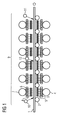
- FIG. 1 A simplified cross-section of this type of apparatus is illustrated in Figure 1 .
- a hot rolled metal plate or strip 1 which requires cooling is transported through the apparatus for controlled cooling on rollers 2.
- the apparatus for controlled cooling 9 consists of a number of top cooling headers 6 and a number of bottom cooling headers 3.
- Figure 1 shows only six top headers and six bottom headers but in practice a typical apparatus for controlled cooling has many more headers.
- the bottom cooling headers 3 spray cooling water jets 5 onto the underside of the plate and top cooling headers 6 spray cooling water jets 8 onto the top surface of the plate.
- the cooling water for the bottom cooling headers 3 is supplied through pipes 4 and the cooling water for the top cooling headers 6 is supplied through pipes 7.
- zone separation sprays are depicted by arrows starting from the zone separation spray devices. Without zone separation sprays the cooling water on the top surface of the plate or strip tends to flow both upstream and downstream, in relation to the direction of movement of the plate or strip, of the apparatus for controlled cooling and consequently the cooling of the top surface will start earlier and/or finish later compared to the bottom surface.
- the cooling water sprayed onto the bottom surface does not flow upstream or downstream partly because the water naturally falls away under gravity and partly because it is blocked by the rollers 2 on which the plate or strip is being transported.
- the direction of movement of the plate or strip is depicted by an arrow at the right end of the plate or strip 1.
- Plates with differing thicknesses and different metallurgical requirements have different cooling requirements and sometimes cooling over the full length of the apparatus for controlled cooling 9 is not required.
- an additional zone separation spray device 12 is used to prevent the cooling water from flowing downstream of the third top header.
- FIG. 1 only shows three zone separation spray devices, one at each end of the apparatus for controlled cooling and one in the centre for dividing the length of the apparatus for controlled cooling 9 into two separate zones.
- a typical apparatus for controlled cooling will have four or more zones and five or more zone separation spray devices.
- a zone separation spray device comprises one or multiple rows of nozzles. Multiple rows are often used so that the first row can stop most of the cooling water from passing through whilst subsequent rows stop any cooling water that gets through the first row.
- a significant problem with a prior art apparatus for controlled cooling as illustrated in Figure 1 is that if the zone separation sprays have sufficient impact pressure to constrain the cooling water when the apparatus for controlled cooling is operating at maximum cooling flow from the cooling headers then the fluid flow out of the zone separation spray devices can significantly affect the cooling when the apparatus for controlled cooling is operating at lower cooling flows from the cooling headers.
- An apparatus for multipurpose interrupted cooling process (MULPIC) as described in EP 0 178 281 A can achieve a 20:1 turndown ratio between maximum and minimum cooling flows from the cooling headers. In order to constrain the cooling water at maximum cooling flow the zone separation sprays are required to have large impact pressures and consequently large flows.
- the flow out of the zone separation spray devices When cooling is done with maximum cooling flow from the cooling headers the flow out of the zone separation spray devices is only a small proportion of the total flow, typically less than 10%. If when working at low cooling flows the same large impact pressure and large flow out of the zone separation sprays that are used during maximum cooling flow are employed, the flow out of the zone separation spray devices is a much higher proportion of the total flow, typically more than 50%.
- the cooling flow is the sum of cooling water flows applied by all the top cooling headers 6 in operation.
- the flow out of the zone separation spray devices is the sum of fluid flows applied by all the zone separation spray devices in operation.
- the total flow is the sum of the cooling flow and the flow out of the zone separation spray devices. The flow out of the zone separation spray devices contributes to the cooling.
- This object is solved by the provision of a method for operating an apparatus for the controlled cooling of hot rolled plate or strip shaped metals by means of a cooling fluid, the apparatus comprising a number of top cooling readers and at least two zone separation spray devices for constraining the cooling fluid on the top surface of the plate or strip to an area, which is characterized in that during cooling the flow out of the zone separation spray devices is adjusted as a function of the cooling flow applied.
- Cooling is done by application of a cooling fluid to the surfaces of the hot rolled plate or strip shaped metals.
- the cooling fluid is water.
- the cooling flow is the sum of flows of cooling fluid applied to the top surface by top cooling headers as shown in Figure 1 . It does not include the flow out of the zone separation spray devices.
- the zone separation spray devices apply fluid flows in the form of jets or streams on the plate or strip shaped metal to constrain the cooling fluid on the top surface of the plate or strip to a desired area. These fluid flows are called zone separation sprays.
- the fluid is usually but not necessarily the same as the cooling fluid.
- the flow out of the zone separation spray devices is not part of the cooling flow.
- Each of the zone separation spray devices can either be adjusted independently from any other zone separation spray device or alternatively there can be a common system for adjusting several or all of the zone separation spray devices together.
- the adjustment of the flow out of the zone separation spray devices can be done by any means for adjusting the flow of a fluid. Preferably, it is done by adjusting an adjustable valve and/or by changing the speed of a variable speed pump.
- the object of the invention is solved by provision of an apparatus for the controlled cooling of hot rolled plate or strip shaped metals by means of a cooling fluid comprising at least two zone separation spray devices for constraining the cooling fluid on the top surface of the plate or strip to an area, characterized in that it comprises at least one device for controlling the flow out of the zone separation spray devices as a function of the cooling flow applied.
- the device for controlling the flow out of the zone separation spray devices may comprise at least one adjustable valve, and/or at least one variable speed pump.
- FIG. 2 shows only a single nozzle 23 of a zone separation spray device but it will be clear that the principle is intended to apply to all the nozzles of a zone separation spray device in an apparatus for controlled cooling.
- an adjustable valve 14 is installed between the water supply line 13 and the zone separation spray nozzle 23.
- the water supply pressure is nominally constant although in practical systems there are small changes in this pressure due to the pump characteristic or the pressure relief valve characteristic.
- the pressure at the zone separation spray nozzle can be changed by opening or closing the adjustable valve 14.
- Closing the valve 14 creates a bigger pressure drop across the valve 14 and consequently the pressure in the zone separation spray nozzle is reduced and the flow out of the zone separation spray device comprising that nozzle 23 is reduced, because the flow out of the nozzle 23 is approximately proportional to the square root of the pressure.
- the flow out of the nozzle is depicted by an arrow.
- zone separation spray devices are operated at high mass flow, high speed, and high impact pressure, and when the cooling flow is lower the zone separation spray devices are operated at lower mass flow, lower speed, and lower impact pressure.
- the flow out of the zone separation spray devices for a given cooling flow is chosen so that it is just sufficient to constrain the cooling water within the relevant section of the apparatus for controlled cooling.
- An alternative embodiment can use a flow-meter instead of the pressure transducer 15.
- the pressure transducer 15 is not absolutely necessary and an alternative embodiment of the invention is illustrated in Figure 3 .
- the signal inducing opening or closing of the valve 14 is generated within the controller 16 by a function 19 which is either a simple lookup table or a calculation based on the magnitude of the cooling flow 17.
- a function 19 which is either a simple lookup table or a calculation based on the magnitude of the cooling flow 17.
- FIG. 4 Another alternative embodiment is illustrated in Figure 4 .
- a pump 20 delivering water from a water supply line 13 to the zone separation spray device is driven by a variable speed motor and drive system 21.
- the signal from the pressure transducer 15 goes into controller 16 where it is compared to a reference pressure signal 18. Any difference between these signals of measured pressure and reference pressure induces changing the operational speed of motor and drive system 21 by a reference signal 22.
- the reference pressure signal 18 is calculated according to the magnitude of the cooling flow 17 so that the flow out of the zone separation spray device is just sufficient to constrain the cooling water.
Landscapes
- Engineering & Computer Science (AREA)
- Mechanical Engineering (AREA)
- Chemical & Material Sciences (AREA)
- Physics & Mathematics (AREA)
- Thermal Sciences (AREA)
- Crystallography & Structural Chemistry (AREA)
- Materials Engineering (AREA)
- Metallurgy (AREA)
- Organic Chemistry (AREA)
- Signal Processing (AREA)
- Computer Networks & Wireless Communication (AREA)
- Heat Treatment Of Strip Materials And Filament Materials (AREA)
- Heat Treatments In General, Especially Conveying And Cooling (AREA)
- Telephonic Communication Services (AREA)
- Mobile Radio Communication Systems (AREA)
Description
- The invention relates to the general field of controlled cooling of hot rolled metal and specifically to the accelerated cooling and direct quenching of steel strips and plates.
- The controlled cooling of hot rolled steel is very important for achieving the desired microstructure and properties of the steel product. Modern plate and hot strip mills generally use powerful cooling systems for this purpose whereby the accurate control of the temperature and the cooling rate are very important. Water is usually used as the cooling fluid.
- One of the most successful designs for an apparatus for controlled cooling is a design with a number of top cooling headers and bottom cooling headers, through which cooling water jets are being sprayed onto the top surface and the underside of the hot rolled metal plate or strip, as described for example in
EP 0178281 A .
A simplified cross-section of this type of apparatus is illustrated inFigure 1 . A hot rolled metal plate or strip 1 which requires cooling is transported through the apparatus for controlled cooling on rollers 2. The apparatus for controlledcooling 9 consists of a number of top cooling headers 6 and a number of bottom cooling headers 3. For clarityFigure 1 shows only six top headers and six bottom headers but in practice a typical apparatus for controlled cooling has many more headers. The bottom cooling headers 3 spraycooling water jets 5 onto the underside of the plate and top cooling headers 6 spray cooling water jets 8 onto the top surface of the plate. The cooling water for the bottom cooling headers 3 is supplied throughpipes 4 and the cooling water for the top cooling headers 6 is supplied through pipes 7. - In order to achieve good flatness of the cooled plates or strips it is very important that the top and bottom cooling are applied at the same time and that the top and bottom cooling are equal. If one surface is cooled before the other then the plate will tend to bow and to form either a gutter or inverted gutter shape or develop another type of flatness problem. In order to ensure that the cooling of the top surface starts and stops at the same time as the cooling of the bottom surface it is common practice to use fluid flows in the form of jets or streams, which are called zone separation sprays and are applied from zone separation spray devices. The zone separation sprays constrain the cooling water on the top surface of the plate or strip to a desired area, in the above example to the area between zone
separation spray devices 10 and 11. The zone separation sprays are depicted by arrows starting from the zone separation spray devices. Without zone separation sprays the cooling water on the top surface of the plate or strip tends to flow both upstream and downstream, in relation to the direction of movement of the plate or strip, of the apparatus for controlled cooling and consequently the cooling of the top surface will start earlier and/or finish later compared to the bottom surface. The cooling water sprayed onto the bottom surface does not flow upstream or downstream partly because the water naturally falls away under gravity and partly because it is blocked by the rollers 2 on which the plate or strip is being transported. The direction of movement of the plate or strip is depicted by an arrow at the right end of the plate or strip 1. - Plates with differing thicknesses and different metallurgical requirements have different cooling requirements and sometimes cooling over the full length of the apparatus for controlled
cooling 9 is not required. In this case it is common practice to switch off some of the top and bottom headers so that a shorter length of the apparatus is used for cooling. For example in the simplified system illustrated inFigure 1 it would be possible to use only the first three top and bottom headers instead of all the top and bottom headers. In this case in order to prevent the cooling water on the top surface of the plate from flowing downstream after the third header an additional zone separation spray device 12 is used to prevent the cooling water from flowing downstream of the third top header. - For clarity
Figure 1 only shows three zone separation spray devices, one at each end of the apparatus for controlled cooling and one in the centre for dividing the length of the apparatus for controlledcooling 9 into two separate zones. In practice a typical apparatus for controlled cooling will have four or more zones and five or more zone separation spray devices. - The principle of operation of the zone separation sprays is that the zone
separation spray devices 10, 11 and 12 are arranged such that the jets of the zone separation sprays are angled in towards the apparatus for controlledcooling 9 and that they have sufficient impact pressure to prevent the cooling water from passing through the zone separation sprays so that the cooling water is forced to travel to the edge of the plate instead of flowing upstream or downstream.
The impact pressure is the product of the mass flow (kilogram per second, kg/s) times the speed (metres per second, m/s) divided by the area of impact (square metre, m2).
The cooling flow of cooling water from the cooling headers on a modern apparatus for controlled cooling can be up to 33 liters per second per square metre or more at maximum flow. Consequently the zone separation sprays require a high mass flow and a high speed to achieve sufficient impact pressure to prevent that large amount of cooling water from passing through. - A zone separation spray device comprises one or multiple rows of nozzles. Multiple rows are often used so that the first row can stop most of the cooling water from passing through whilst subsequent rows stop any cooling water that gets through the first row.
- A significant problem with a prior art apparatus for controlled cooling as illustrated in
Figure 1 is that if the zone separation sprays have sufficient impact pressure to constrain the cooling water when the apparatus for controlled cooling is operating at maximum cooling flow from the cooling headers then the fluid flow out of the zone separation spray devices can significantly affect the cooling when the apparatus for controlled cooling is operating at lower cooling flows from the cooling headers. An apparatus for multipurpose interrupted cooling process (MULPIC) as described inEP 0 178 281 A can achieve a 20:1 turndown ratio between maximum and minimum cooling flows from the cooling headers. In order to constrain the cooling water at maximum cooling flow the zone separation sprays are required to have large impact pressures and consequently large flows. - When cooling is done with maximum cooling flow from the cooling headers the flow out of the zone separation spray devices is only a small proportion of the total flow, typically less than 10%.
If when working at low cooling flows the same large impact pressure and large flow out of the zone separation sprays that are used during maximum cooling flow are employed, the flow out of the zone separation spray devices is a much higher proportion of the total flow, typically more than 50%.
The cooling flow is the sum of cooling water flows applied by all the top cooling headers 6 in operation. The flow out of the zone separation spray devices is the sum of fluid flows applied by all the zone separation spray devices in operation. The total flow is the sum of the cooling flow and the flow out of the zone separation spray devices. The flow out of the zone separation spray devices contributes to the cooling. - In the above example of a turndown ration between maximum and minimum cooling flow the proportion of the flow of the zone separation sprays will be twenty times higher at minimum cooling flow than at maximum cooling flow. By that large amount of fluid applied by the zone separation sprays in addition to the cooling flow the cooling process is affected negatively, since top and bottom cooling may become unequal due to large differences between the amounts of fluids which cool the top surface and the underside.
- It will be apparent that whilst the description above refers to a MULPIC type cooling system the principle applies to any cooling system which utilizes zone separation sprays to constrain the cooling water on the top surface of the plate or strip being cooled.
- It is the object of the present invention to provide a method and an apparatus for controlled cooling of hot rolled plate or strip shaped metals which diminishes affect of the cooling process by the contribution of the flow out of the zone separation spray devices to the total flow.
- This object is solved by the provision of a method for operating an apparatus for the controlled cooling of hot rolled plate or strip shaped metals by means of a cooling fluid, the apparatus comprising a number of top cooling readers and at least two zone separation spray devices for constraining the cooling fluid on the top surface of the plate or strip to an area, which is characterized in that during cooling the flow out of the zone separation spray devices is adjusted as a function of the cooling flow applied.
- Cooling is done by application of a cooling fluid to the surfaces of the hot rolled plate or strip shaped metals. Preferably, the cooling fluid is water. The cooling flow is the sum of flows of cooling fluid applied to the top surface by top cooling headers as shown in
Figure 1 . It does not include the flow out of the zone separation spray devices.
The zone separation spray devices apply fluid flows in the form of jets or streams on the plate or strip shaped metal to constrain the cooling fluid on the top surface of the plate or strip to a desired area. These fluid flows are called zone separation sprays. The fluid is usually but not necessarily the same as the cooling fluid. The flow out of the zone separation spray devices is not part of the cooling flow. - By adjusting the flow out of the zone separation spray devices as a function of the cooling flow applied it can be ensured that the proportion of the flow out of the zone separation spray devices is a small proportion of the total flow at high cooling flow operation as well as at low cooling flow operation. The higher or lower the cooling flow, the higher or lower the flow out of the zone separation spray devices is adjusted, thereby always simultaneously ensuring that the impact pressure of the zone separation sprays is high enough to prevent cooling fluid from passing through and that its proportion of the total flow is small enough to not affect the cooling process significantly. The proportion of the total flow may be up to 20 %, preferably up to 10 %.
- Each of the zone separation spray devices can either be adjusted independently from any other zone separation spray device or alternatively there can be a common system for adjusting several or all of the zone separation spray devices together.
- The adjustment of the flow out of the zone separation spray devices can be done by any means for adjusting the flow of a fluid. Preferably, it is done by adjusting an adjustable valve and/or by changing the speed of a variable speed pump.
- To accurately adjust the flow out of the zone separation spray devices it is monitored, preferably by measuring its pressure.
- Furthermore, the object of the invention is solved by provision of an apparatus for the controlled cooling of hot rolled plate or strip shaped metals by means of a cooling fluid comprising at least two zone separation spray devices for constraining the cooling fluid on the top surface of the plate or strip to an area, characterized in that it comprises at least one device for controlling the flow out of the zone separation spray devices as a function of the cooling flow applied.
- There can be one device for controlling the flow out of several or all the zone separation spray devices together. Alternatively for each one of the zone separation spray devices there can be one device for controlling the flow in another embodiment of the invention. The device for controlling the flow out of the zone separation spray devices may comprise at least one adjustable valve, and/or at least one variable speed pump.
- For controlling the flow out of the zone separation devices the device for controlling the flow out of the zone separation spray devices may comprise at least one pressure transducer for measuring the pressure of the flow and/or at least one flow meter for measuring the flow.
- Schematic representations of the prior art and of exemplary embodiments of the invention are described in schematic
Figures 1 to 4 . -
Figure 1 shows a simplified cross section of an apparatus for controlled cooling according to the state of the art. -
Figure 2 shows a schematic illustration of a single nozzle of an embodiment of a zone separation spray device with an adjustable valve and a pressure transducer. -
Figure 3 shows a schematic illustration of a single nozzle of an embodiment of a zone separation spray device with an adjustable valve. -
Figure 4 shows a schematic illustration of a single nozzle of an embodiment of a zone separation spray device with a variable speed pump and a pressure transducer. - For simplicity
Figure 2 shows only asingle nozzle 23 of a zone separation spray device but it will be clear that the principle is intended to apply to all the nozzles of a zone separation spray device in an apparatus for controlled cooling. InFigure 2 anadjustable valve 14 is installed between thewater supply line 13 and the zoneseparation spray nozzle 23. The water supply pressure is nominally constant although in practical systems there are small changes in this pressure due to the pump characteristic or the pressure relief valve characteristic. The pressure at the zone separation spray nozzle can be changed by opening or closing theadjustable valve 14. Closing thevalve 14 creates a bigger pressure drop across thevalve 14 and consequently the pressure in the zone separation spray nozzle is reduced and the flow out of the zone separation spray device comprising thatnozzle 23 is reduced, because the flow out of thenozzle 23 is approximately proportional to the square root of the pressure. The flow out of the nozzle is depicted by an arrow. - In the exemplary embodiment illustrated in
Figure 2 apressure transducer 15 is used to monitor the pressure in the zone separation spray nozzle. The signal from thepressure transducer 15 goes intocontroller 16 where it is compared to areference pressure signal 18. Any difference between these signals of measured pressure and reference pressure induces opening or closing of thevalve 14 so as to reduce the difference. Hence thecontroller 16 is a device for controlling the flow out of zone separation spray devices. Thereference pressure signal 18 is calculated based on the magnitude of the coolingflow 17 applied and the known pressure versus flow characteristic of the zone separation spray nozzles. By these means the flow out of zone separation spray devices is adjusted according to the cooling flow, i.e. as a function of the cooling flow, so that when the cooling flow is large the zone separation spray devices are operated at high mass flow, high speed, and high impact pressure, and when the cooling flow is lower the zone separation spray devices are operated at lower mass flow, lower speed, and lower impact pressure. The flow out of the zone separation spray devices for a given cooling flow is chosen so that it is just sufficient to constrain the cooling water within the relevant section of the apparatus for controlled cooling. - An alternative embodiment can use a flow-meter instead of the
pressure transducer 15. - The
pressure transducer 15 is not absolutely necessary and an alternative embodiment of the invention is illustrated inFigure 3 . In this embodiment the signal inducing opening or closing of thevalve 14 is generated within thecontroller 16 by afunction 19 which is either a simple lookup table or a calculation based on the magnitude of the coolingflow 17. During the commissioning of the apparatus for controlled cooling the setting ofvalve 14 for a given cooling flow is adjusted manually so that it is just sufficient to constrain the cooling water and then the manual settings are stored infunction 19 as either a lookup table or a simple formula. - Another alternative embodiment is illustrated in
Figure 4 . In this embodiment apump 20 delivering water from awater supply line 13 to the zone separation spray device is driven by a variable speed motor anddrive system 21. The signal from thepressure transducer 15 goes intocontroller 16 where it is compared to areference pressure signal 18. Any difference between these signals of measured pressure and reference pressure induces changing the operational speed of motor anddrive system 21 by areference signal 22. Thereference pressure signal 18 is calculated according to the magnitude of the coolingflow 17 so that the flow out of the zone separation spray device is just sufficient to constrain the cooling water. -
1 plate or strip 2 roller 3 bottom cooling header 4 pipe 5 cooling water jet 6 top cooling header 7 pipe 8 cooling water jet 9 apparatus for controlled cooling 10 zone separation spray device 11 zone separation spray device 12 zone separation spray device 13 water supply line 14 valve 15 pressure transducer 16 controller 17 magnitude of the cooling flow 18 reference pressure signal 19 function 20 pump 21 motor and drive system 22 reference signal 23 nozzle
Claims (9)
- Method for operating an apparatus for the controlled cooling of hot rolled plate or strip shaped metals by means of a cooling fluid, the apparatus comprising a number of top cooling headers (6) and at least two zone separation spray devices (10, 11, 12) for constraining the cooling fluid on the top surface of the plate or strip to an area, characterized in that during cooling the flow out of the zone separation spray devices (10, 11, 12) is adjusted as a function of the cooling flow applied.
- Method according to claim 1, characterized in that the flow out of the zone separation spray devices (10, 11, 12) is adjusted by adjusting an adjustable valve (14).
- Method according to claim 1 or 2, characterized in that the flow out of the zone separation spray devices (10, 11, 12) is adjusted by changing the speed of a variable speed pump (20).
- Method according to any one of the preceding claims, characterized in that the flow out of the zone separation spray devices (10, 11, 12) is monitored by measuring its pressure.
- Apparatus for the controlled cooling (9) of hot rolled plate or strip (1) shaped metals by means of a cooling fluid, the apparatus comprising a number of top cooling headers (6) and at least two zone separation spray devices (10, 11, 12), for constraining the cooling device on the top surface of the plate or strip to an area, characterized in that it comprises at least one device for controlling the flow out of the zone separation spray devices as a function of the cooling flow applied.
- Apparatus according to claim 5, characterized in that the device for controlling the flow out of the zone separation spray devices (10, 11, 12) comprises at least one adjustable valve (14).
- Apparatus according to claim 5 or 6, characterized in that the device for controlling the flow out of the zone separation spray devices (10, 11, 12) comprises at least one variable speed pump (20).
- Apparatus according to any one of claims 5 to 7, characterized in that the device for controlling the flow out of the zone separation spray devices comprises at least one pressure transducer (15) for measuring the pressure of the flow out of the zone separation devices (10, 11, 12).
- Apparatus according to any one of claims 5 to 8, characterized in that the device for controlling the flow out of the zone separation spray devices comprises at least one flow meter for measuring the flow out of the zone separation devices (10, 11, 12).
Priority Applications (2)
| Application Number | Priority Date | Filing Date | Title |
|---|---|---|---|
| PL09730976T PL2274113T3 (en) | 2008-04-07 | 2009-03-19 | Method and apparatus for controlled cooling |
| EP09730976.9A EP2274113B1 (en) | 2008-04-07 | 2009-03-19 | Method and apparatus for controlled cooling |
Applications Claiming Priority (3)
| Application Number | Priority Date | Filing Date | Title |
|---|---|---|---|
| EP08251349A EP2108465A1 (en) | 2008-04-07 | 2008-04-07 | Method and apparatus for controlled cooling |
| PCT/EP2009/053248 WO2009124830A1 (en) | 2008-04-07 | 2009-03-19 | Method and apparatus for controlled cooling |
| EP09730976.9A EP2274113B1 (en) | 2008-04-07 | 2009-03-19 | Method and apparatus for controlled cooling |
Publications (2)
| Publication Number | Publication Date |
|---|---|
| EP2274113A1 EP2274113A1 (en) | 2011-01-19 |
| EP2274113B1 true EP2274113B1 (en) | 2013-05-01 |
Family
ID=39511015
Family Applications (2)
| Application Number | Title | Priority Date | Filing Date |
|---|---|---|---|
| EP08251349A Ceased EP2108465A1 (en) | 2008-04-07 | 2008-04-07 | Method and apparatus for controlled cooling |
| EP09730976.9A Not-in-force EP2274113B1 (en) | 2008-04-07 | 2009-03-19 | Method and apparatus for controlled cooling |
Family Applications Before (1)
| Application Number | Title | Priority Date | Filing Date |
|---|---|---|---|
| EP08251349A Ceased EP2108465A1 (en) | 2008-04-07 | 2008-04-07 | Method and apparatus for controlled cooling |
Country Status (11)
| Country | Link |
|---|---|
| US (2) | US8412253B2 (en) |
| EP (2) | EP2108465A1 (en) |
| JP (1) | JP2011516274A (en) |
| KR (1) | KR101686012B1 (en) |
| CN (1) | CN101983108B (en) |
| BR (1) | BRPI0910981A2 (en) |
| DK (1) | DK2274113T3 (en) |
| ES (1) | ES2422734T3 (en) |
| PL (1) | PL2274113T3 (en) |
| RU (1) | RU2490082C2 (en) |
| WO (1) | WO2009124830A1 (en) |
Cited By (1)
| Publication number | Priority date | Publication date | Assignee | Title |
|---|---|---|---|---|
| DE102020205252A1 (en) | 2020-04-24 | 2021-10-28 | Kocks Technik Gmbh & Co Kg | Long product cooling device and method for long product cooling using the same |
Families Citing this family (9)
| Publication number | Priority date | Publication date | Assignee | Title |
|---|---|---|---|---|
| WO2009126072A1 (en) * | 2008-04-08 | 2009-10-15 | Telefonaktiebolaget L M Ericsson (Publ) | A poc server and a mobile terminal comprising a poc client for providing poc communication services |
| US9008297B2 (en) * | 2008-10-22 | 2015-04-14 | At&T Intellectual Property I, L.P. | Methods, computer program products, and systems for providing called party initiated priority marking |
| EP2644719A1 (en) * | 2012-03-28 | 2013-10-02 | Siemens Aktiengesellschaft | Cooling control |
| KR101393086B1 (en) * | 2012-12-27 | 2014-05-12 | 주식회사 포스코 | Electricity generating apparatus using cooling water of hot rolling system |
| EP2767352A1 (en) * | 2013-02-14 | 2014-08-20 | Siemens VAI Metals Technologies GmbH | Cooling of a metal strip with position-regulated valve device |
| US9693207B2 (en) | 2015-02-26 | 2017-06-27 | Sony Corporation | Unified notification and response system |
| KR101943989B1 (en) | 2015-06-05 | 2019-01-30 | 삼성전자주식회사 | Method, server and terminal for transmitting and receiving data |
| DE102017206540A1 (en) * | 2017-04-18 | 2018-10-18 | Sms Group Gmbh | Apparatus and method for cooling metal strips or sheets |
| EP3599037A1 (en) | 2018-07-25 | 2020-01-29 | Primetals Technologies Germany GmbH | Cooling section with adjustment of the cooling agent flow by means of pumping |
Family Cites Families (26)
| Publication number | Priority date | Publication date | Assignee | Title |
|---|---|---|---|---|
| US3880358A (en) * | 1973-08-15 | 1975-04-29 | Edward J Schaming | Coolant distribution and control system for metal rolling mills and the like |
| US4149703A (en) * | 1978-01-31 | 1979-04-17 | Drever Company | Apparatus for quenching a heated metal plate |
| US4691549A (en) * | 1981-12-24 | 1987-09-08 | United Engineering Rolling Mills, Inc. | Apparatus for removing liquid from a strip in a rolling mill and method thereof |
| BE900784A (en) | 1984-10-09 | 1985-04-09 | Centre Rech Metallurgique | DEVICE FOR COOLING A MOVING METAL PRODUCT AND INSTALLATION COMPRISING THE APPLICATION. |
| SU1400689A1 (en) * | 1986-03-17 | 1988-06-07 | Всесоюзный Научно-Исследовательский И Проектный Институт По Очистке Технологических Газов,Сточных Вод И Использованию Вторичных Энергоресурсов Предприятий Черной Металлургии | Arrangement for adjusting the cooling of moving strip steel rolled stock |
| JPH06249B2 (en) * | 1989-12-13 | 1994-01-05 | 新日本製鐵株式会社 | Rapid cooling method for hot rolled material |
| US5262071A (en) * | 1992-01-06 | 1993-11-16 | W. R. Grace & Co.-Conn. | Metalworking fluid management system |
| EP0627965B1 (en) * | 1992-02-24 | 1998-12-02 | Alcan International Limited | Process for applying and removing liquid coolant to control temperature of continuously moving metal strip |
| CN2261898Y (en) * | 1996-07-05 | 1997-09-10 | 鞍山钢铁公司 | Plate control cooling device |
| FR2757933B1 (en) * | 1996-12-27 | 1999-01-22 | Commissariat Energie Atomique | DEVICE FOR DYNAMICALLY SEPARATING TWO ZONES BY AT LEAST ONE BUFFER ZONE AND TWO CURTAINS OF CLEAN AIR |
| JPH11197734A (en) * | 1998-01-21 | 1999-07-27 | Sumitomo Metal Ind Ltd | Method and apparatus for spraying hot-rolled steel sheet |
| AU4596899A (en) * | 1998-07-10 | 2000-02-01 | Ipsco Inc. | Method and apparatus for producing martensite- or bainite-rich steel using steckel mill and controlled cooling |
| FR2789757B1 (en) * | 1999-02-16 | 2001-05-11 | Selas Sa | DEVICE FOR EXCHANGING HEAT WITH A FLAT PRODUCT |
| DE19943403A1 (en) * | 1999-09-10 | 2001-03-22 | Siemens Ag | Method and device for cooling a hot-rolled steel strip emerging from a roll stand |
| DE19963185A1 (en) * | 1999-12-27 | 2001-07-12 | Siemens Ag | Method and device for cooling a hot-rolled metal strip emerging from a roll stand |
| DE19963186B4 (en) * | 1999-12-27 | 2005-04-14 | Siemens Ag | Method for controlling and / or regulating the cooling section of a hot strip mill for rolling metal strip and associated device |
| DE10130445A1 (en) * | 2001-06-23 | 2003-01-02 | Sms Demag Ag | Method and arrangement of nozzles for variable width lubrication of a roll stand |
| DE10131369A1 (en) * | 2001-06-28 | 2003-01-09 | Sms Demag Ag | Method and device for cooling and lubricating rolls of a roll stand |
| US20050016242A1 (en) * | 2001-08-03 | 2005-01-27 | Ryurou Kurahashi | Continous hot-rolling facility |
| US6659728B2 (en) * | 2001-11-09 | 2003-12-09 | Viking Pump, Inc. | Liquid dispensing pump system |
| JP4214134B2 (en) * | 2004-06-23 | 2009-01-28 | 新日本製鐵株式会社 | Thick steel plate cooling device |
| US20060102620A1 (en) * | 2004-11-12 | 2006-05-18 | Ntn Corporation | Heat treat process |
| KR101244110B1 (en) * | 2005-08-01 | 2013-03-18 | 에브너 인두스트리오펜바우 게엠베하 | Device for cooling a metal strip |
| DE102005049077B4 (en) * | 2005-10-13 | 2009-02-12 | Infineon Technologies Ag | Method for transmitting media data, communication network unit and computer program element |
| DE102006032088A1 (en) * | 2006-07-11 | 2008-01-17 | Infineon Technologies Ag | Communication terminal, method for sending communication data, conference server equipment and method for forwarding communication data |
| WO2008013318A1 (en) * | 2006-07-27 | 2008-01-31 | Jfe Steel Corporation | Cooler and cooling method of hot rolled steel band |
-
2008
- 2008-04-07 EP EP08251349A patent/EP2108465A1/en not_active Ceased
- 2008-04-08 US US12/936,440 patent/US8412253B2/en not_active Expired - Fee Related
-
2009
- 2009-03-19 BR BRPI0910981A patent/BRPI0910981A2/en not_active IP Right Cessation
- 2009-03-19 RU RU2010145143/02A patent/RU2490082C2/en not_active IP Right Cessation
- 2009-03-19 JP JP2011503395A patent/JP2011516274A/en active Pending
- 2009-03-19 PL PL09730976T patent/PL2274113T3/en unknown
- 2009-03-19 EP EP09730976.9A patent/EP2274113B1/en not_active Not-in-force
- 2009-03-19 DK DK09730976.9T patent/DK2274113T3/en active
- 2009-03-19 ES ES09730976T patent/ES2422734T3/en active Active
- 2009-03-19 US US12/936,410 patent/US20110107776A1/en not_active Abandoned
- 2009-03-19 WO PCT/EP2009/053248 patent/WO2009124830A1/en not_active Ceased
- 2009-03-19 CN CN200980111899.1A patent/CN101983108B/en not_active Expired - Fee Related
- 2009-03-19 KR KR1020107024912A patent/KR101686012B1/en not_active Expired - Fee Related
Cited By (2)
| Publication number | Priority date | Publication date | Assignee | Title |
|---|---|---|---|---|
| DE102020205252A1 (en) | 2020-04-24 | 2021-10-28 | Kocks Technik Gmbh & Co Kg | Long product cooling device and method for long product cooling using the same |
| US12385105B2 (en) | 2020-04-24 | 2025-08-12 | Kocks Technik Gmbh & Co Kg | Apparatus for cooling long products and method of cooling a long product using the same |
Also Published As
| Publication number | Publication date |
|---|---|
| BRPI0910981A2 (en) | 2016-01-05 |
| KR20110005840A (en) | 2011-01-19 |
| RU2010145143A (en) | 2012-05-20 |
| CN101983108B (en) | 2016-01-06 |
| RU2490082C2 (en) | 2013-08-20 |
| WO2009124830A1 (en) | 2009-10-15 |
| DK2274113T3 (en) | 2013-05-21 |
| US20110034203A1 (en) | 2011-02-10 |
| US20110107776A1 (en) | 2011-05-12 |
| PL2274113T3 (en) | 2014-01-31 |
| JP2011516274A (en) | 2011-05-26 |
| US8412253B2 (en) | 2013-04-02 |
| KR101686012B1 (en) | 2016-12-22 |
| ES2422734T3 (en) | 2013-09-13 |
| EP2274113A1 (en) | 2011-01-19 |
| EP2108465A1 (en) | 2009-10-14 |
| CN101983108A (en) | 2011-03-02 |
Similar Documents
| Publication | Publication Date | Title |
|---|---|---|
| EP2108465A1 (en) | Method and apparatus for controlled cooling | |
| EP2415536B1 (en) | Cooling device for hot rolled steel sheet | |
| RU2386505C1 (en) | Method for cooldown of steel plate | |
| JP6355828B2 (en) | Hybrid cooling and rolling of oil and water | |
| WO2008053947A1 (en) | Method of cooling hot-rolled steel strip | |
| TWI731415B (en) | Cooling device for hot-rolled steel sheet and cooling method for hot-rolled steel sheet | |
| WO2014103164A1 (en) | Cooling method and cooling device for hot-rolled steel strip | |
| EP1992426B1 (en) | Cooling apparatus for hot rolled steel band and method of cooling the steel band | |
| US8318080B2 (en) | Device and method for cooling hot strip | |
| CA2894480C (en) | Device and method for cooling rolled stock | |
| US11484926B2 (en) | Cooling bar and cooling process with variable cooling rate for steel sheets | |
| EP2979769A1 (en) | Thick steel plate manufacturing method and manufacturing device | |
| JP2009220158A (en) | Apparatus and method for cooling steel | |
| KR101159907B1 (en) | Apparatus for controlling temperature of finishing mill and method thereof | |
| EP2726225B1 (en) | Device and method for the removal of scale from a metal product | |
| JP4337157B2 (en) | Steel plate cooling method and apparatus | |
| JP4661226B2 (en) | Steel plate cooling method and cooling device | |
| JP2009144189A (en) | Steel plate cooling method and apparatus | |
| CN121038910A (en) | Reversible roughing mills and related processes for aluminum or aluminum alloy products |
Legal Events
| Date | Code | Title | Description |
|---|---|---|---|
| PUAI | Public reference made under article 153(3) epc to a published international application that has entered the european phase |
Free format text: ORIGINAL CODE: 0009012 |
|
| 17P | Request for examination filed |
Effective date: 20100917 |
|
| AK | Designated contracting states |
Kind code of ref document: A1 Designated state(s): AT BE BG CH CY CZ DE DK EE ES FI FR GB GR HR HU IE IS IT LI LT LU LV MC MK MT NL NO PL PT RO SE SI SK TR |
|
| AX | Request for extension of the european patent |
Extension state: AL BA RS |
|
| DAX | Request for extension of the european patent (deleted) | ||
| GRAP | Despatch of communication of intention to grant a patent |
Free format text: ORIGINAL CODE: EPIDOSNIGR1 |
|
| GRAS | Grant fee paid |
Free format text: ORIGINAL CODE: EPIDOSNIGR3 |
|
| GRAA | (expected) grant |
Free format text: ORIGINAL CODE: 0009210 |
|
| AK | Designated contracting states |
Kind code of ref document: B1 Designated state(s): AT BE BG CH CY CZ DE DK EE ES FI FR GB GR HR HU IE IS IT LI LT LU LV MC MK MT NL NO PL PT RO SE SI SK TR |
|
| REG | Reference to a national code |
Ref country code: GB Ref legal event code: FG4D |
|
| REG | Reference to a national code |
Ref country code: AT Ref legal event code: REF Ref document number: 609563 Country of ref document: AT Kind code of ref document: T Effective date: 20130515 Ref country code: CH Ref legal event code: EP |
|
| REG | Reference to a national code |
Ref country code: DK Ref legal event code: T3 |
|
| REG | Reference to a national code |
Ref country code: IE Ref legal event code: FG4D |
|
| REG | Reference to a national code |
Ref country code: SE Ref legal event code: TRGR |
|
| REG | Reference to a national code |
Ref country code: DE Ref legal event code: R096 Ref document number: 602009015416 Country of ref document: DE Effective date: 20130627 |
|
| REG | Reference to a national code |
Ref country code: RO Ref legal event code: EPE |
|
| REG | Reference to a national code |
Ref country code: GB Ref legal event code: 732E Free format text: REGISTERED BETWEEN 20130627 AND 20130703 |
|
| RAP2 | Party data changed (patent owner data changed or rights of a patent transferred) |
Owner name: SIEMENS PLC. |
|
| REG | Reference to a national code |
Ref country code: FR Ref legal event code: TP Owner name: SIEMENS PLC, GB Effective date: 20130806 |
|
| REG | Reference to a national code |
Ref country code: ES Ref legal event code: FG2A Ref document number: 2422734 Country of ref document: ES Kind code of ref document: T3 Effective date: 20130913 |
|
| REG | Reference to a national code |
Ref country code: DE Ref legal event code: R081 Ref document number: 602009015416 Country of ref document: DE Owner name: SIEMENS PLC., GB Free format text: FORMER OWNER: SIEMENS VAI METALS TECHNOLOGIES LTD., SHEFFIELD, GB Effective date: 20130729 Ref country code: DE Ref legal event code: R081 Ref document number: 602009015416 Country of ref document: DE Owner name: SIEMENS PLC., FRIMLEY, GB Free format text: FORMER OWNER: SIEMENS VAI METALS TECHNOLOGIES LTD., SHEFFIELD, YORKSHIRE, GB Effective date: 20130729 Ref country code: DE Ref legal event code: R081 Ref document number: 602009015416 Country of ref document: DE Owner name: PRIMETALS TECHNOLOGIES, LTD., GB Free format text: FORMER OWNER: SIEMENS VAI METALS TECHNOLOGIES LTD., SHEFFIELD, YORKSHIRE, GB Effective date: 20130729 |
|
| REG | Reference to a national code |
Ref country code: NL Ref legal event code: VDEP Effective date: 20130501 |
|
| REG | Reference to a national code |
Ref country code: LT Ref legal event code: MG4D |
|
| PG25 | Lapsed in a contracting state [announced via postgrant information from national office to epo] |
Ref country code: NO Free format text: LAPSE BECAUSE OF FAILURE TO SUBMIT A TRANSLATION OF THE DESCRIPTION OR TO PAY THE FEE WITHIN THE PRESCRIBED TIME-LIMIT Effective date: 20130801 Ref country code: GR Free format text: LAPSE BECAUSE OF FAILURE TO SUBMIT A TRANSLATION OF THE DESCRIPTION OR TO PAY THE FEE WITHIN THE PRESCRIBED TIME-LIMIT Effective date: 20130802 Ref country code: SI Free format text: LAPSE BECAUSE OF FAILURE TO SUBMIT A TRANSLATION OF THE DESCRIPTION OR TO PAY THE FEE WITHIN THE PRESCRIBED TIME-LIMIT Effective date: 20130501 Ref country code: IS Free format text: LAPSE BECAUSE OF FAILURE TO SUBMIT A TRANSLATION OF THE DESCRIPTION OR TO PAY THE FEE WITHIN THE PRESCRIBED TIME-LIMIT Effective date: 20130901 Ref country code: LT Free format text: LAPSE BECAUSE OF FAILURE TO SUBMIT A TRANSLATION OF THE DESCRIPTION OR TO PAY THE FEE WITHIN THE PRESCRIBED TIME-LIMIT Effective date: 20130501 Ref country code: PT Free format text: LAPSE BECAUSE OF FAILURE TO SUBMIT A TRANSLATION OF THE DESCRIPTION OR TO PAY THE FEE WITHIN THE PRESCRIBED TIME-LIMIT Effective date: 20130902 |
|
| PG25 | Lapsed in a contracting state [announced via postgrant information from national office to epo] |
Ref country code: BG Free format text: LAPSE BECAUSE OF FAILURE TO SUBMIT A TRANSLATION OF THE DESCRIPTION OR TO PAY THE FEE WITHIN THE PRESCRIBED TIME-LIMIT Effective date: 20130801 Ref country code: CY Free format text: LAPSE BECAUSE OF FAILURE TO SUBMIT A TRANSLATION OF THE DESCRIPTION OR TO PAY THE FEE WITHIN THE PRESCRIBED TIME-LIMIT Effective date: 20130501 Ref country code: HR Free format text: LAPSE BECAUSE OF FAILURE TO SUBMIT A TRANSLATION OF THE DESCRIPTION OR TO PAY THE FEE WITHIN THE PRESCRIBED TIME-LIMIT Effective date: 20130501 |
|
| PG25 | Lapsed in a contracting state [announced via postgrant information from national office to epo] |
Ref country code: LV Free format text: LAPSE BECAUSE OF FAILURE TO SUBMIT A TRANSLATION OF THE DESCRIPTION OR TO PAY THE FEE WITHIN THE PRESCRIBED TIME-LIMIT Effective date: 20130501 |
|
| PG25 | Lapsed in a contracting state [announced via postgrant information from national office to epo] |
Ref country code: EE Free format text: LAPSE BECAUSE OF FAILURE TO SUBMIT A TRANSLATION OF THE DESCRIPTION OR TO PAY THE FEE WITHIN THE PRESCRIBED TIME-LIMIT Effective date: 20130501 Ref country code: SK Free format text: LAPSE BECAUSE OF FAILURE TO SUBMIT A TRANSLATION OF THE DESCRIPTION OR TO PAY THE FEE WITHIN THE PRESCRIBED TIME-LIMIT Effective date: 20130501 |
|
| REG | Reference to a national code |
Ref country code: PL Ref legal event code: T3 |
|
| PG25 | Lapsed in a contracting state [announced via postgrant information from national office to epo] |
Ref country code: NL Free format text: LAPSE BECAUSE OF FAILURE TO SUBMIT A TRANSLATION OF THE DESCRIPTION OR TO PAY THE FEE WITHIN THE PRESCRIBED TIME-LIMIT Effective date: 20130501 |
|
| PLBE | No opposition filed within time limit |
Free format text: ORIGINAL CODE: 0009261 |
|
| STAA | Information on the status of an ep patent application or granted ep patent |
Free format text: STATUS: NO OPPOSITION FILED WITHIN TIME LIMIT |
|
| 26N | No opposition filed |
Effective date: 20140204 |
|
| REG | Reference to a national code |
Ref country code: DE Ref legal event code: R097 Ref document number: 602009015416 Country of ref document: DE Effective date: 20140204 |
|
| PG25 | Lapsed in a contracting state [announced via postgrant information from national office to epo] |
Ref country code: LU Free format text: LAPSE BECAUSE OF FAILURE TO SUBMIT A TRANSLATION OF THE DESCRIPTION OR TO PAY THE FEE WITHIN THE PRESCRIBED TIME-LIMIT Effective date: 20140319 |
|
| REG | Reference to a national code |
Ref country code: CH Ref legal event code: PL |
|
| REG | Reference to a national code |
Ref country code: IE Ref legal event code: MM4A |
|
| PG25 | Lapsed in a contracting state [announced via postgrant information from national office to epo] |
Ref country code: LI Free format text: LAPSE BECAUSE OF NON-PAYMENT OF DUE FEES Effective date: 20140331 Ref country code: IE Free format text: LAPSE BECAUSE OF NON-PAYMENT OF DUE FEES Effective date: 20140319 Ref country code: CH Free format text: LAPSE BECAUSE OF NON-PAYMENT OF DUE FEES Effective date: 20140331 |
|
| REG | Reference to a national code |
Ref country code: AT Ref legal event code: PC Ref document number: 609563 Country of ref document: AT Kind code of ref document: T Owner name: SIEMENS PLC, GB Effective date: 20150417 |
|
| REG | Reference to a national code |
Ref country code: GB Ref legal event code: 732E Free format text: REGISTERED BETWEEN 20150521 AND 20150527 |
|
| PG25 | Lapsed in a contracting state [announced via postgrant information from national office to epo] |
Ref country code: MT Free format text: LAPSE BECAUSE OF FAILURE TO SUBMIT A TRANSLATION OF THE DESCRIPTION OR TO PAY THE FEE WITHIN THE PRESCRIBED TIME-LIMIT Effective date: 20130501 |
|
| REG | Reference to a national code |
Ref country code: FR Ref legal event code: PLFP Year of fee payment: 8 |
|
| PG25 | Lapsed in a contracting state [announced via postgrant information from national office to epo] |
Ref country code: MC Free format text: LAPSE BECAUSE OF FAILURE TO SUBMIT A TRANSLATION OF THE DESCRIPTION OR TO PAY THE FEE WITHIN THE PRESCRIBED TIME-LIMIT Effective date: 20130501 |
|
| PG25 | Lapsed in a contracting state [announced via postgrant information from national office to epo] |
Ref country code: HU Free format text: LAPSE BECAUSE OF FAILURE TO SUBMIT A TRANSLATION OF THE DESCRIPTION OR TO PAY THE FEE WITHIN THE PRESCRIBED TIME-LIMIT; INVALID AB INITIO Effective date: 20090319 |
|
| REG | Reference to a national code |
Ref country code: DE Ref legal event code: R082 Ref document number: 602009015416 Country of ref document: DE Representative=s name: KINNSTAETTER, KLAUS, DIPL.-PHYS.UNIV., DE |
|
| REG | Reference to a national code |
Ref country code: DE Ref legal event code: R082 Ref document number: 602009015416 Country of ref document: DE Representative=s name: KINNSTAETTER, KLAUS, DIPL.-PHYS.UNIV., DE Ref country code: DE Ref legal event code: R081 Ref document number: 602009015416 Country of ref document: DE Owner name: PRIMETALS TECHNOLOGIES, LTD., GB Free format text: FORMER OWNER: SIEMENS PLC., FRIMLEY, CAMBERLY, GB |
|
| REG | Reference to a national code |
Ref country code: ES Ref legal event code: PC2A Owner name: PRIMETALS TECHNOLOGIES, LIMITED Effective date: 20170210 |
|
| REG | Reference to a national code |
Ref country code: FR Ref legal event code: PLFP Year of fee payment: 9 |
|
| PGFP | Annual fee paid to national office [announced via postgrant information from national office to epo] |
Ref country code: SE Payment date: 20170321 Year of fee payment: 9 Ref country code: DE Payment date: 20170322 Year of fee payment: 9 Ref country code: FI Payment date: 20170313 Year of fee payment: 9 Ref country code: FR Payment date: 20170322 Year of fee payment: 9 Ref country code: RO Payment date: 20170228 Year of fee payment: 9 |
|
| PGFP | Annual fee paid to national office [announced via postgrant information from national office to epo] |
Ref country code: PL Payment date: 20170222 Year of fee payment: 9 Ref country code: GB Payment date: 20170322 Year of fee payment: 9 Ref country code: CZ Payment date: 20170317 Year of fee payment: 9 Ref country code: BE Payment date: 20170321 Year of fee payment: 9 Ref country code: AT Payment date: 20170322 Year of fee payment: 9 Ref country code: DK Payment date: 20170321 Year of fee payment: 9 |
|
| PGFP | Annual fee paid to national office [announced via postgrant information from national office to epo] |
Ref country code: ES Payment date: 20170315 Year of fee payment: 9 Ref country code: TR Payment date: 20170221 Year of fee payment: 9 |
|
| REG | Reference to a national code |
Ref country code: FR Ref legal event code: TP Owner name: PRIMETALS TECHNOLOGIES, LIMITED, GB Effective date: 20170630 |
|
| PGFP | Annual fee paid to national office [announced via postgrant information from national office to epo] |
Ref country code: IT Payment date: 20170323 Year of fee payment: 9 |
|
| REG | Reference to a national code |
Ref country code: AT Ref legal event code: PC Ref document number: 609563 Country of ref document: AT Kind code of ref document: T Owner name: PRIMETALS TECHNOLOGIES, LIMITED, GB Effective date: 20171207 |
|
| PG25 | Lapsed in a contracting state [announced via postgrant information from national office to epo] |
Ref country code: MK Free format text: LAPSE BECAUSE OF FAILURE TO SUBMIT A TRANSLATION OF THE DESCRIPTION OR TO PAY THE FEE WITHIN THE PRESCRIBED TIME-LIMIT Effective date: 20130501 |
|
| REG | Reference to a national code |
Ref country code: DE Ref legal event code: R119 Ref document number: 602009015416 Country of ref document: DE |
|
| REG | Reference to a national code |
Ref country code: DK Ref legal event code: EBP Effective date: 20180331 |
|
| PG25 | Lapsed in a contracting state [announced via postgrant information from national office to epo] |
Ref country code: FI Free format text: LAPSE BECAUSE OF NON-PAYMENT OF DUE FEES Effective date: 20180319 Ref country code: RO Free format text: LAPSE BECAUSE OF NON-PAYMENT OF DUE FEES Effective date: 20180319 Ref country code: SE Free format text: LAPSE BECAUSE OF NON-PAYMENT OF DUE FEES Effective date: 20180320 |
|
| REG | Reference to a national code |
Ref country code: AT Ref legal event code: MM01 Ref document number: 609563 Country of ref document: AT Kind code of ref document: T Effective date: 20180319 |
|
| GBPC | Gb: european patent ceased through non-payment of renewal fee |
Effective date: 20180319 |
|
| PG25 | Lapsed in a contracting state [announced via postgrant information from national office to epo] |
Ref country code: CZ Free format text: LAPSE BECAUSE OF NON-PAYMENT OF DUE FEES Effective date: 20180319 |
|
| REG | Reference to a national code |
Ref country code: BE Ref legal event code: MM Effective date: 20180331 Ref country code: BE Ref legal event code: PD Owner name: PRIMETALS TECHNOLOGIES, LIMITED; GB Free format text: DETAILS ASSIGNMENT: CHANGE OF OWNER(S), AFFECTATION / CESSION; FORMER OWNER NAME: SIEMENS PLC. Effective date: 20161214 |
|
| PG25 | Lapsed in a contracting state [announced via postgrant information from national office to epo] |
Ref country code: AT Free format text: LAPSE BECAUSE OF NON-PAYMENT OF DUE FEES Effective date: 20180319 Ref country code: DE Free format text: LAPSE BECAUSE OF NON-PAYMENT OF DUE FEES Effective date: 20181002 |
|
| PG25 | Lapsed in a contracting state [announced via postgrant information from national office to epo] |
Ref country code: BE Free format text: LAPSE BECAUSE OF NON-PAYMENT OF DUE FEES Effective date: 20180331 Ref country code: GB Free format text: LAPSE BECAUSE OF NON-PAYMENT OF DUE FEES Effective date: 20180319 Ref country code: IT Free format text: LAPSE BECAUSE OF NON-PAYMENT OF DUE FEES Effective date: 20180319 |
|
| PG25 | Lapsed in a contracting state [announced via postgrant information from national office to epo] |
Ref country code: FR Free format text: LAPSE BECAUSE OF NON-PAYMENT OF DUE FEES Effective date: 20180331 |
|
| PG25 | Lapsed in a contracting state [announced via postgrant information from national office to epo] |
Ref country code: DK Free format text: LAPSE BECAUSE OF NON-PAYMENT OF DUE FEES Effective date: 20180331 |
|
| REG | Reference to a national code |
Ref country code: ES Ref legal event code: FD2A Effective date: 20190911 |
|
| PG25 | Lapsed in a contracting state [announced via postgrant information from national office to epo] |
Ref country code: ES Free format text: LAPSE BECAUSE OF NON-PAYMENT OF DUE FEES Effective date: 20180320 |
|
| PG25 | Lapsed in a contracting state [announced via postgrant information from national office to epo] |
Ref country code: PL Free format text: LAPSE BECAUSE OF NON-PAYMENT OF DUE FEES Effective date: 20180319 |
|
| PG25 | Lapsed in a contracting state [announced via postgrant information from national office to epo] |
Ref country code: TR Free format text: LAPSE BECAUSE OF NON-PAYMENT OF DUE FEES Effective date: 20180319 |