EP2274069B1 - A kitchen hood assembly with a combination cleaning and fire suppression system - Google Patents
A kitchen hood assembly with a combination cleaning and fire suppression system Download PDFInfo
- Publication number
- EP2274069B1 EP2274069B1 EP09739284.9A EP09739284A EP2274069B1 EP 2274069 B1 EP2274069 B1 EP 2274069B1 EP 09739284 A EP09739284 A EP 09739284A EP 2274069 B1 EP2274069 B1 EP 2274069B1
- Authority
- EP
- European Patent Office
- Prior art keywords
- hood
- riser
- cleaning
- spray bar
- fire
- Prior art date
- Legal status (The legal status is an assumption and is not a legal conclusion. Google has not performed a legal analysis and makes no representation as to the accuracy of the status listed.)
- Active
Links
Images





Classifications
-
- F—MECHANICAL ENGINEERING; LIGHTING; HEATING; WEAPONS; BLASTING
- F24—HEATING; RANGES; VENTILATING
- F24C—DOMESTIC STOVES OR RANGES ; DETAILS OF DOMESTIC STOVES OR RANGES, OF GENERAL APPLICATION
- F24C15/00—Details
- F24C15/20—Removing cooking fumes
- F24C15/2057—Removing cooking fumes using a cleaning liquid
-
- A—HUMAN NECESSITIES
- A62—LIFE-SAVING; FIRE-FIGHTING
- A62C—FIRE-FIGHTING
- A62C3/00—Fire prevention, containment or extinguishing specially adapted for particular objects or places
- A62C3/006—Fire prevention, containment or extinguishing specially adapted for particular objects or places for kitchens or stoves
Definitions
- the present invention relates to cleaning and suppressing fires in kitchen hood assemblies.
- a kitchen hood assembly includes a combination cleaning and fire suppression system. That is, the hood assembly is operative in one mode to inject water or an aqueous solution into the hood structure to clean the same. In a second mode of operation, in response to a fire being detected in or adjacent to the hood, the same system injects water or an aqueous solution into the hood to suppress a fire.
- the kitchen hood assembly comprises a combination hood cleaning and fire suppression system.
- This hood assembly includes a hood structure and a riser connected to the hood structure and extending therefrom.
- An exhaust blower is provided for forcing an exhaust stream of air into and through the riser.
- the combination hood cleaning and fire suppression system incorporated into the hood structure is adapted in a cleaning mode to spray water and a surfactant within the kitchen hood to clean the same, and in a fire suppression mode in response to a signal from a fire sensor, spray water and a surfactant into the kitchen hood to know down and suppress the fire.
- the present invention includes a kitchen hood assembly having a combination hood cleaning and fire suppression system according to claim 1. It comprises:
- the invention concerns a method of cleaning a kitchen hood and suppressing fires in and about the hood according to claim 9. It comprises:
- kitchen hood assembly 10 comprises a housing 12 generally defining the outer structure. Disposed within hood assembly 10 is a combination cleaning and fire suppression system 20 comprising a spray bar 22 and a control system 26 as shown in Figures 2 , 3 , and 4 .
- housing 12 encloses a vapor entrainment area 14 comprising a portion of the interior of the housing as illustrated in Figure 1 .
- kitchen hood assembly 10 is mounted such that it is spaced above a cooking surface or similar device in order that vapors produced in cooking are entrained upwards into vapor entrainment area 14.
- Kitchen hood assembly 10 includes a grease confinement area 16 that is separated from vapor entrainment area 14 by an inclined panel 15 as shown particularly in Figures 2 and 4A .
- Mounted within panel 15 is a filter 15A through which the entrained vapors may flow into grease confinement area 16.
- riser 18 Mounted to an upper portion of hood assembly 10 and in fluid communication with grease confinement area 16 is a riser or duct 18 extending away from the hood assembly.
- Riser 18 includes an interior 18A to receive vapors from grease confinement area 16 and conduct the vapors away from hood assembly 10.
- An exhaust blower is disposed in fluid communication with riser 18. The exhaust blower maintains a draft through riser 18 to facilitate entraining vapor in vapor entrainment area 14 and directing the vapors through filter 15A into grease confinement area 16 and subsequently through riser 18 to be exhausted away from hood assembly 10.
- Spray bar 22 extends generally transversely across an upper portion of the grease confinement area 16. See Figures 2 and 3 .
- Spray bar 22 includes a series of spaced-apart nozzles 22A and at least one riser nozzle 22B.
- Nozzles 22A are typically angled to direct spray to the inner surfaces of the grease confinement area 16. Nozzles 22A may, however, be directed at various angles and all nozzles need not be directed in the same direction.
- Each nozzle 22A has a spray pattern, spacing, and direction such that a spray of an appropriately pressurized aqueous liquid, such as water and a surfactant, from the nozzles impinges on the interior surfaces of grease confinement area 16 to remove contaminants, including grease and generally clean the hood in this area.
- At least one nozzle 22B is positioned to align with the center of the horizontal cross-section of riser 18. See Figures 2 , 3 , and 4A .
- Nozzle 22B is directed generally upward such that a spray of an appropriately pressurized liquid from the nozzle is directed into the center of riser 18.
- spray bar 22 includes a series of pipe segments 23 connected together by a series of tees 22E as illustrated particularly in Figure 3 .
- Nozzles 22A and 22B are associated with the tees 22E.
- the riser nozzle 22B is generally oriented in position to direct an aqueous liquid into the riser 18.
- Spray bar 22 in the embodiment illustrated in Figure 3 is offset with respect to the center of riser 18.
- an arm 27 that extends between the tee 22E and the nozzle 22B.
- control system 26 includes a manifold 21 ( Figure 6 ) for connecting spray bar 22 to a source of water, a surfactant controller 26B, and a surfactant reservoir 26C.
- Manifold 21 is constructed generally of pipe and fittings by common methods.
- the configuration of manifold 21, in one embodiment, includes a pair of vertically-oriented tubular inlet legs 21A, 21B and a vertical tubular outlet leg 21C ( Figure 6 ).
- the vertically-oriented legs 21A, 21B, 21C are connected and in fluid communication with a horizontal connector 21D. Water from two sources may thus be provided to manifold 21.
- heated water may be directed into inlet 21E of leg 21A and unheated water may be directed into inlet 21F of leg 21B.
- the heated and unheated water is directed through manual shut-off valves 21G (one in each of legs 21A, 21B) and electronic solenoid valves 21H (one in each of legs 21A, 21B) into connector 21D from whence the mixed heated and unheated water is directed into leg 21C and into spray bar 22.
- spray bar 22 is in fluid communication with leg 21C by an upper connector 21M.
- each leg 21A, 21B includes a manual shutoff valve 21G and an electric solenoid valve 21H.
- Leg 21C includes a temperature sensor 21K.
- Control system 26 may include the capacity to respond to a desired temperature set point and adjust the flow of heated and unheated water to obtain and maintain the temperature of the water flowing in leg 21C at a certain temperature or within a temperature range.
- Control system 26 also includes a surfactant injection apparatus to inject surfactant into the water directed to spray bar 22.
- the apparatus includes a surfactant pump system 26B and a surfactant reservoir 26C.
- the pump inlet is fluidly connected to reservoir 26C by tube 29A, and the pump outlet is connected to connector 21M by tube 29B. It is appreciated that a check valve may be interposed between the connection of tube 29B to connector 21M and surfactant pump system 26B to prevent backflow through the surfactant pump system.
- Control system 26 further includes commonly known circuitry and logic for activating system 20 by admitting supply water into the system for a set or desired time period. During the time period that water is being injected into cleaning and fire suppression system 20, control system 26 controls the amount of surfactant injected by surfactant pump 26B.
- the cleaning and fire suppression system 20 further includes a fire sensor 30 that is mounted on riser 18, or in an area in the hood, such that the sensor is operative to be activated by a fire in interior 18A of the riser 18 or grease confinement area 16.
- fire sensor 30 includes an active sensing element extending at least partially into interior 18A.
- Fire sensor 30 may be of various extant designs that provide an electrical signal that may be used to initiate operation of combination cleaning and fire suppression system 20 in the event of a fire being detected as will be discussed here below.
- a control schematic for control system 26 that enables both hood cleaning and fire suppression is illustrated in Figure 7 .
- Components that make-up the controls may, in one embodiment, be housed within control system cabinet 26A ( Figure 2 ).
- the elements include an uninterruptible power supply or battery back up device that is operable to automatically maintain power to the system during a power outage. Electrical power from AC supply 1 is supplied to a DC power supply which in turn provides DC electrical power for control system 26.
- the hood exhaust blower is powered by an AC motor and is controlled by a manual shut-off switch 11.
- the control elements require DC electrical power that may be provided by the DC power supply and battery back-up device.
- the battery back-up device includes the capability to sense the state of AC supply 1, that capability indicated by dashed line 2.
- Exhaust blower shut-off switch 11 which generally is a manually actuated on-off switch, is coupled to a wash switch 12 such that closing switch 11 opens switch 12, and opening switch 11 closes switch 12.
- the coupling of switches 11 and 12 may be of various known forms including a mechanical linkage and electrical relays. With switches 11 and 12 thus coupled, when the exhaust blower is operating, cleaning with cleaning and fire suppression system 20 is not normally energized. This is the normal operation of hood 10 in which, for example, cooking of foods is occurring under or near the hood.
- the exhaust blower may be de-energized by manually opening switch 11 as would, for example, be the case at the end of a cooking period.
- switch 11 When switch 11 is opened, switch 12 closes and energizes water valves 21H to admit water into manifold 21 and surfactant pump system 26B to provide surfactant such that cleaning and fire suppression system 20 performs a cleaning cycle for range hood assembly 10.
- a timer switch is provided in series with switch 12 and is operable to de-energize water valves 21H and surfactant pump 26B upon completing a desired or set cleaning period.
- the power supply is DC. However, it is appreciated that AC power could be used to power the control system 26 shown in Figure 7 . Various components of the system would be changed to make them AC compatible. Further, a back-up power source, such as an AC generator, could be used.
- Fire sensor 30 is coupled to a fire switch 13, the coupling symbolically indicated in Figure 7 by dashed line 4.
- fire sensor 30 closes fire switch 13 to energize water valves 21H and surfactant pump 26B.
- Line 5 connects to switch 13 and effectively interconnects the DC power supply and battery back-up to the water valves 21H and surfactant pump system 26B. This connection by-passes switch 12 and the timer switch. Whether the exhaust blower is energized or not, should a fire be sensed by fire sensor 30, fire switch 13 closes and energizes valves 21H and pump system 26B for fire suppression. Thus energized, water and surfactant is sprayed into hood assembly 10, including into riser 18, to suppress the fire.
- a manual reset feature of common design may be provided to de-energize cleaning and fire suppression system 20 when the fire is suppressed.
- switch 13 may be configured to open and de-energize valves 21H and surfactant pump system 26B.
- cleaning and fire suppression system 20 functions similarly during cleaning and fire suppression. Once energized, whether by manual shut-off of hood assembly 10 or by a fire being sensed by fire sensor 30, system 20 functions the same way using the same aqueous liquid.
- cleaning and fire suppression system 20 may be supplied with water having a temperature between about 60 °C (140 °F) and about 77 °C (170 °F).
- water pressure may be maintained at about 0,2 MPa (30 psi).
- Nozzles 22A can provide a flow of about 0,159 m 3 /h (0,7 gpm) 0,2 MPa (30 psi).
- Riser nozzle 22B may be rated to provide 0,454 m 3 /h (2,4 gpm) 0,2 MPa (30 psi).
- nozzles 22A are equivalent to Macola Model No. 2591 or 2592 and nozzles 22B are equivalent to Macola Model No. 2593.
- Spray bar 22 comprises 19,05 mm (3/4 ") pipe nipples 23 and 24, tees 22E, and elbows.
- Riser nipple 27 comprises 6,35 mm (1/4 ") tubing or pipe and commonly available fittings to connect to spray bar 22.
- pipe nipples 23 are about 305 mm (12 ") long and provide for nozzles 22A to be spaced apart about 330,2 mm (13 ”) and preferably spaced at between 317,5 and 342,9 mm (12 1/2" and 13 1/2"). It is appreciated that all of these sizes discussed above can vary and will probably vary depending upon application.
- Fire suppression sensor 30 should be of a design capable of sensing the presence of fire typical of range hood systems.
- Hood drain 28 is typically formed of brass pipe and fittings. In one embodiment, 38,1 mm (1 1/2") pipe is used in forming hood drain 28, and the hood drain extends at least 1,83 m (72") away from hood assembly 10.
- control system 26 provides for surfactant to be injected for 1 second for every minute of operation.
- the surfactant is effective in the fire suppression mode to knockdown the fire.
- the amount of surfactant administered during a fire and the time period for injecting a surfactant can vary. However, in a preferred design and process, surfactant is continuously injected into the water stream in a fire situation.
- the new kitchen hood assembly of the present invention utilizes substantially the same structure and system for both cleaning the hood assembly and for fire prevention. Also, it should be pointed out that the kitchen hood assembly disclosed herein and the fire proof prevention system is fully certified to Standard UL300.
Landscapes
- Engineering & Computer Science (AREA)
- Chemical & Material Sciences (AREA)
- Combustion & Propulsion (AREA)
- Mechanical Engineering (AREA)
- General Engineering & Computer Science (AREA)
- Health & Medical Sciences (AREA)
- Public Health (AREA)
- Business, Economics & Management (AREA)
- Emergency Management (AREA)
- Ventilation (AREA)
- Buildings Adapted To Withstand Abnormal External Influences (AREA)
- Special Wing (AREA)
Description
- The present invention relates to cleaning and suppressing fires in kitchen hood assemblies.
- Commercial kitchen hood assemblies, cleaning systems for commercial kitchen hoods, and fire suppression systems for suppressing fires in commercial kitchen hoods are known. See, for example,
U.S. 2007/209655 (the '655 publication);FR 2865419 U.S. 4,085,735 (the '735 patent). In the case of the '655 publication and the '419 patent, the fire suppression systems disclosed therein are completely separate from the system that is used to clean the kitchen hood assembly. The fact that these systems are not integrated gives rise to duplicate hardware and control systems. The '735 patent discloses an air ventilation and washing system for extracting noxious and impure air that is found in and around cooking surfacers in a kitchen. In addition, inU.S. 4,186,727 , there is disclosed an air ventilation and washing system for removing grease laden air that is produced in a kitchen, as well as a washing system for cleaning accumulation of grease within the system. Finally,U.S. 3,805,685 discloses a ventilation and grease extraction system that is adapted to extract grease and grease vapors from in and around kitchen surfaces of a commercial kitchen. - A kitchen hood assembly is provided and includes a combination cleaning and fire suppression system. That is, the hood assembly is operative in one mode to inject water or an aqueous solution into the hood structure to clean the same. In a second mode of operation, in response to a fire being detected in or adjacent to the hood, the same system injects water or an aqueous solution into the hood to suppress a fire.
- In one embodiment, the kitchen hood assembly comprises a combination hood cleaning and fire suppression system. This hood assembly includes a hood structure and a riser connected to the hood structure and extending therefrom. An exhaust blower is provided for forcing an exhaust stream of air into and through the riser. The combination hood cleaning and fire suppression system incorporated into the hood structure is adapted in a cleaning mode to spray water and a surfactant within the kitchen hood to clean the same, and in a fire suppression mode in response to a signal from a fire sensor, spray water and a surfactant into the kitchen hood to know down and suppress the fire.
- In another embodiment, the present invention includes a kitchen hood assembly having a combination hood cleaning and fire suppression system according to claim 1. It comprises:
- a. a hood structure for mounting above a cooking surface;
- b. a grease filter disposed in the hood structure and extending transversely across the hood structure, the grease filter mounted in an inclined panel;
- c. a riser connected to the hood structure and having an interior for receiving an exhaust stream and conducting the exhaust stream away from the hood structure;
- d. the riser extending upwardly from a top portion of the hood structure, and wherein the riser is in fluid communication with a grease confinement area, the grease confinement area separated from a vapor entrainment area by the inclined panel;
- e. an exhaust blower for forcing the exhaust stream into and through the riser; characterized by:
- f. a combination hood cleaning and fire suppression system incorporated into the hood structure, including:
- i) an inlet manifold for connecting to at least one water source to provide water to the manifold;
- ii) a spray bar fluidly coupled to the inlet manifold and extending within the hood structure;
- iii) said spray bar including an elongated conduit extending transversely through the hood structure and below the riser;
- iv) the spray bar being spaced from the grease filter and located in the open transverse space of the hood structure between the grease filter and the back panel of the hood structure, and wherein the spray bar extends through a substantial width of the open transverse space between the grease filter and the back panel;
- v) a surfactant injector operatively connected to the hood cleaning and fire suppression system for injecting surfactant into the water received in the spray bar;
- vi) a series of nozzles spaced from the grease filter and laterally spaced in the transverse open space formed by the grease filter and the back panel, the series of nozzles being in fluid communication with the spray bar such that a liquid cleaning or fire suppression solution directed into the spray bar is sprayed into the transverse open space by the series of nozzles;
- vii) wherein at least one of the series of nozzles includes a riser nozzle that is directed upwardly towards the interior of the riser such that the riser nozzle is operative to spray the cleaning or fire suppression solution upwardly into the interior of the riser;
- viii) a fire sensor disposed adjacent the riser;
- ix) a control system that in one mode of operation actuates the hood cleaning and fire suppression system for cleaning the kitchen hood and in another mode of operation, in response to a signal from the fire sensor, actuates the hood cleaning and fire suppression system to suppress a fire; and
- x) wherein the control system includes a clean switch that is activated by shutting the blower off and that is adapted to actuate the hood cleaning and fire suppression system to clean the hood structure in response to shutting the blower off.
- In another embodiment, the invention concerns a method of cleaning a kitchen hood and suppressing fires in and about the hood according to claim 9. It comprises:
- a. forming an aqueous liquid by mixing hot and cold water to form a water mixture and maintaining the temperature of the water mixture at approximately 60°C (140°F) to approximately 76°C (170°F) and directing the water mixture into a spray bar disposed in the kitchen hood and injecting a surfactant into the mixture of water and pressurizing the aqueous liquid in the spray bar;
- b. in a cleaning mode supplying the aqueous liquid to the spray bar disposed in the kitchen hood, distributing the aqueous liquid within the hood and cleaning the hood, and draining the aqueous liquid from the hood;
- c. wherein the method includes shutting off an exhaust blower associated with the hood and in response to shutting off the exhaust blower initiating the cleaning mode and supplying the aqueous liquid to the spray bar for cleaning the hood, wherein shutting off the exhaust blower actuates a clean switch that in turn initiates the cleaning mode; and
- d. in fire suppression mode, in response to a signal from a fire sensor, supplying the aqueous liquid to the same spray bar disposed in the kitchen hood, distributing the aqueous liquid within the hood, suppressing a fire in or about the hood, and draining the aqueous liquid from the hood,
- wherein the hood includes a transverse rear compartment bounded in part at least by a grease filter, a back panel, and a portion of the top of the hood, and wherein there is a riser extending upwardly from the top of the hood and communicatively connected to the rear compartment such that an exhaust stream is constrained to move through the grease filter, through the rear compartment, and into and trough the riser;
- wherein the method includes in both the cleaning mode and the fire suppression mode, directing an aqueous solution through the spray bar that is spaced from the grease filter and extends transversely through the rear compartment and spraying the aqueous solution from a series of laterally spaced nozzles supported by the spray bar and spaced throughout the rear compartment;
- wherein the spray bar is transversely disposed below the riser, and the method includes spraying the aqueous solution from a riser nozzle supported on the spray bar at a point below the riser, and wherein the riser nozzle is directed generally upwardly towards the riser such that aqueous solution sprayed from the riser nozzle is directed upwardly into an interior area of the riser; and
- wherein the method is applied to the kitchen hood assembly of claim 1.
- Other objects and advantages of the present invention will become apparent and obvious from a study of the following description and the accompanying drawings.
-
-
Figure 1 is a perspective view of the kitchen hood assembly with the combination cleaning and fire suppression system. -
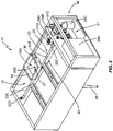
Figure 2 is a perspective of the kitchen hood assembly with a top portion thereof removed to better illustrate the combination cleaning and fire suppression system. -
Figure 3 is a top plan view of the kitchen hood with a top portion removed to better illustrate internal components of the hood. -
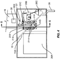
Figure 4 is a side sectional view of the kitchen hood assembly taken through the line 4-4 ofFigure 3 . -
Figure 4A is a side sectional view of the kitchen hood assembly taken through theline 4A-4A ofFigure 3 . -
Figure 5 is a front sectional view of the kitchen hood assembly with the combination cleaning and fire suppression system. -
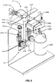
Figure 6 is a fragmentary perspective view of the kitchen hood assembly showing the control system. -
Figure 7 is a schematic illustration of the control system. - With further reference to the drawings, the kitchen hood assembly of the present invention is shown therein and indicated generally by the
numeral 10. As illustrated inFigure 1 ,kitchen hood assembly 10 comprises ahousing 12 generally defining the outer structure. Disposed withinhood assembly 10 is a combination cleaning andfire suppression system 20 comprising aspray bar 22 and acontrol system 26 as shown inFigures 2 ,3 , and4 . - Turning now to a more detailed description of
kitchen hood assembly 10,housing 12 encloses avapor entrainment area 14 comprising a portion of the interior of the housing as illustrated inFigure 1 . In a typical application,kitchen hood assembly 10 is mounted such that it is spaced above a cooking surface or similar device in order that vapors produced in cooking are entrained upwards intovapor entrainment area 14.Kitchen hood assembly 10 includes agrease confinement area 16 that is separated fromvapor entrainment area 14 by aninclined panel 15 as shown particularly inFigures 2 and4A . Mounted withinpanel 15 is afilter 15A through which the entrained vapors may flow intogrease confinement area 16. Mounted to an upper portion ofhood assembly 10 and in fluid communication withgrease confinement area 16 is a riser orduct 18 extending away from the hood assembly.Riser 18 includes an interior 18A to receive vapors fromgrease confinement area 16 and conduct the vapors away fromhood assembly 10. An exhaust blower is disposed in fluid communication withriser 18. The exhaust blower maintains a draft throughriser 18 to facilitate entraining vapor invapor entrainment area 14 and directing the vapors throughfilter 15A intogrease confinement area 16 and subsequently throughriser 18 to be exhausted away fromhood assembly 10. - Disposed within
grease confinement area 16 is a portion of the combination cleaning andfire suppression system 20.Spray bar 22 extends generally transversely across an upper portion of thegrease confinement area 16. SeeFigures 2 and3 .Spray bar 22 includes a series of spaced-apartnozzles 22A and at least oneriser nozzle 22B. Nozzles 22A are typically angled to direct spray to the inner surfaces of thegrease confinement area 16.Nozzles 22A may, however, be directed at various angles and all nozzles need not be directed in the same direction. Eachnozzle 22A has a spray pattern, spacing, and direction such that a spray of an appropriately pressurized aqueous liquid, such as water and a surfactant, from the nozzles impinges on the interior surfaces ofgrease confinement area 16 to remove contaminants, including grease and generally clean the hood in this area. At least onenozzle 22B is positioned to align with the center of the horizontal cross-section ofriser 18. SeeFigures 2 ,3 , and4A .Nozzle 22B is directed generally upward such that a spray of an appropriately pressurized liquid from the nozzle is directed into the center ofriser 18. - In one embodiment,
spray bar 22 includes a series ofpipe segments 23 connected together by a series oftees 22E as illustrated particularly inFigure 3 .Nozzles tees 22E. Note that theriser nozzle 22B is generally oriented in position to direct an aqueous liquid into theriser 18.Spray bar 22 in the embodiment illustrated inFigure 3 is offset with respect to the center ofriser 18. In order to positionnozzle 22B generally centrally with respect to theriser 18, there is provided anarm 27 that extends between thetee 22E and thenozzle 22B. - Turning now to control system 26 (
Fig. 6 ), the control system includes a manifold 21 (Figure 6 ) for connectingspray bar 22 to a source of water, asurfactant controller 26B, and asurfactant reservoir 26C.Manifold 21 is constructed generally of pipe and fittings by common methods. The configuration ofmanifold 21, in one embodiment, includes a pair of vertically-orientedtubular inlet legs 21A, 21B and a verticaltubular outlet leg 21C (Figure 6 ). The vertically-orientedlegs horizontal connector 21D. Water from two sources may thus be provided tomanifold 21. For example, heated water may be directed intoinlet 21E ofleg 21A and unheated water may be directed intoinlet 21F of leg 21B. The heated and unheated water is directed through manual shut-offvalves 21G (one in each oflegs 21A, 21B) andelectronic solenoid valves 21H (one in each oflegs 21A, 21B) intoconnector 21D from whence the mixed heated and unheated water is directed intoleg 21C and intospray bar 22. It is noted thatspray bar 22 is in fluid communication withleg 21C by anupper connector 21M. - As noted above, each
leg 21A, 21B includes amanual shutoff valve 21G and anelectric solenoid valve 21H.Leg 21C includes atemperature sensor 21K.Control system 26 may include the capacity to respond to a desired temperature set point and adjust the flow of heated and unheated water to obtain and maintain the temperature of the water flowing inleg 21C at a certain temperature or within a temperature range. -
Control system 26 also includes a surfactant injection apparatus to inject surfactant into the water directed tospray bar 22. In one embodiment, the apparatus includes asurfactant pump system 26B and asurfactant reservoir 26C. The pump inlet is fluidly connected toreservoir 26C bytube 29A, and the pump outlet is connected toconnector 21M bytube 29B. It is appreciated that a check valve may be interposed between the connection oftube 29B toconnector 21M andsurfactant pump system 26B to prevent backflow through the surfactant pump system. -
Control system 26 further includes commonly known circuitry and logic for activatingsystem 20 by admitting supply water into the system for a set or desired time period. During the time period that water is being injected into cleaning andfire suppression system 20,control system 26 controls the amount of surfactant injected bysurfactant pump 26B. - The cleaning and
fire suppression system 20 further includes afire sensor 30 that is mounted onriser 18, or in an area in the hood, such that the sensor is operative to be activated by a fire in interior 18A of theriser 18 orgrease confinement area 16. In one embodiment,fire sensor 30 includes an active sensing element extending at least partially into interior 18A.Fire sensor 30 may be of various extant designs that provide an electrical signal that may be used to initiate operation of combination cleaning andfire suppression system 20 in the event of a fire being detected as will be discussed here below. - A control schematic for
control system 26 that enables both hood cleaning and fire suppression is illustrated inFigure 7 . Components that make-up the controls may, in one embodiment, be housed withincontrol system cabinet 26A (Figure 2 ). The elements include an uninterruptible power supply or battery back up device that is operable to automatically maintain power to the system during a power outage. Electrical power from AC supply 1 is supplied to a DC power supply which in turn provides DC electrical power forcontrol system 26. Typically, the hood exhaust blower is powered by an AC motor and is controlled by a manual shut-off switch 11. Also typically, the control elements require DC electrical power that may be provided by the DC power supply and battery back-up device. The battery back-up device includes the capability to sense the state of AC supply 1, that capability indicated by dashed line 2. When a power outage is detected, the battery back-up supplies vialine 3 the DC power to maintain operation of cleaning andfire suppression system 20 during the power outage. Exhaust blower shut-off switch 11, which generally is a manually actuated on-off switch, is coupled to awash switch 12 such that closingswitch 11 opens switch 12, and openingswitch 11 closes switch 12. The coupling ofswitches switches fire suppression system 20 is not normally energized. This is the normal operation ofhood 10 in which, for example, cooking of foods is occurring under or near the hood. The exhaust blower may be de-energized by manually openingswitch 11 as would, for example, be the case at the end of a cooking period. Whenswitch 11 is opened,switch 12 closes and energizeswater valves 21H to admit water intomanifold 21 andsurfactant pump system 26B to provide surfactant such that cleaning andfire suppression system 20 performs a cleaning cycle forrange hood assembly 10. In one embodiment, a timer switch is provided in series withswitch 12 and is operable to de-energizewater valves 21H andsurfactant pump 26B upon completing a desired or set cleaning period. In the example just discussed, the power supply is DC. However, it is appreciated that AC power could be used to power thecontrol system 26 shown inFigure 7 . Various components of the system would be changed to make them AC compatible. Further, a back-up power source, such as an AC generator, could be used. -
Fire sensor 30 is coupled to afire switch 13, the coupling symbolically indicated inFigure 7 by dashedline 4. When a fire inrange hood 10 occurs,fire sensor 30 closesfire switch 13 to energizewater valves 21H andsurfactant pump 26B.Line 5 connects to switch 13 and effectively interconnects the DC power supply and battery back-up to thewater valves 21H andsurfactant pump system 26B. This connection by-passes switch 12 and the timer switch. Whether the exhaust blower is energized or not, should a fire be sensed byfire sensor 30,fire switch 13 closes and energizesvalves 21H andpump system 26B for fire suppression. Thus energized, water and surfactant is sprayed intohood assembly 10, including intoriser 18, to suppress the fire. A manual reset feature of common design may be provided to de-energize cleaning andfire suppression system 20 when the fire is suppressed. Alternatively, when the level of fire suppression is such thatfire sensor 30 no longer senses a fire, switch 13 may be configured to open and de-energizevalves 21H andsurfactant pump system 26B. - It is appreciated that cleaning and
fire suppression system 20 functions similarly during cleaning and fire suppression. Once energized, whether by manual shut-off ofhood assembly 10 or by a fire being sensed byfire sensor 30,system 20 functions the same way using the same aqueous liquid. - To be effective in cleaning
hood assembly 10, cleaning andfire suppression system 20 may be supplied with water having a temperature between about 60 °C (140 °F) and about 77 °C (170 °F). To be effective in cleaning and fire suppression, water pressure may be maintained at about 0,2 MPa (30 psi).Nozzles 22A can provide a flow of about 0,159 m3/h (0,7 gpm) 0,2 MPa (30 psi).Riser nozzle 22B may be rated to provide 0,454 m3/h (2,4 gpm) 0,2 MPa (30 psi). In a typical application,nozzles 22A are equivalent to Macola Model No. 2591 or 2592 andnozzles 22B are equivalent to Macola Model No. 2593. All plumbing is brass pipe or tube.Spray bar 22 comprises 19,05 mm (3/4 ")pipe nipples tees 22E, and elbows.Riser nipple 27 comprises 6,35 mm (1/4 ") tubing or pipe and commonly available fittings to connect to spraybar 22. In a typical application,pipe nipples 23 are about 305 mm (12 ") long and provide fornozzles 22A to be spaced apart about 330,2 mm (13 ") and preferably spaced at between 317,5 and 342,9 mm (12 1/2" and 13 1/2"). It is appreciated that all of these sizes discussed above can vary and will probably vary depending upon application.Fire suppression sensor 30 should be of a design capable of sensing the presence of fire typical of range hood systems. Fire sensors are well known in the art and are commercially available.Hood drain 28 is typically formed of brass pipe and fittings. In one embodiment, 38,1 mm (1 1/2") pipe is used in forminghood drain 28, and the hood drain extends at least 1,83 m (72") away fromhood assembly 10. - Commonly available surfactants may be used and function also as detergents. Generally, during cleaning or fire suppression,
control system 26 provides for surfactant to be injected for 1 second for every minute of operation. The surfactant is effective in the fire suppression mode to knockdown the fire. The amount of surfactant administered during a fire and the time period for injecting a surfactant can vary. However, in a preferred design and process, surfactant is continuously injected into the water stream in a fire situation. - There are many advantages to the new kitchen hood assembly of the present invention. One principal advantage is that the kitchen hood assembly utilizes substantially the same structure and system for both cleaning the hood assembly and for fire prevention. Also, it should be pointed out that the kitchen hood assembly disclosed herein and the fire proof prevention system is fully certified to Standard UL300.
- The present invention may, of course, be carried out in other specific ways than those herein set forth without departing from the scope of the appended claims . The present embodiments are therefore to be construed in all aspects as illustrative and not restrictive.
Claims (10)
- A kitchen hood assembly (10) having a combination hood cleaning and fire suppression system (20), comprising:a. a hood structure (12) for mounting above a cooking surface;b. a grease filter (15A) disposed in the hood structure (12) and extending transversely across the hood structure, the grease filter mounted in an inclined panel (15A);c. a riser (18) connected to the hood structure and having an interior (18A) for receiving an exhaust stream and conducting the exhaust stream away from the hood structure;d. the riser (18) extending upwardly from a top portion of the hood structure, and wherein the riser is in fluid communication with a grease confinement area (16), the grease confinement area separated from a vapor entrainment area (14) by the inclined panel (15A);e. an exhaust blower for forcing the exhaust stream into and through the riser (18); characterized by:f. a combination hood cleaning and fire suppression system (20) incorporated into the hood structure (12), including:i) an inlet manifold (21A, 21B) for connecting to at least one water source to provide water to the manifold;ii) a spray bar (22) fluidly coupled to the inlet manifold and extending within the hood structure;iii) said spray bar (22) including an elongated conduit (23) extending transversely through the hood structure and below the riser (18);iv) the spray bar (22) being spaced from the grease filter (15A) and located in the open transverse space of the hood structure (12) between the grease filter and the back panel (15) of the hood structure, and wherein the spray bar extends through a substantial width of the open transverse space between the grease filter and the back panel;v) a surfactant injector (26) operatively connected to the hood cleaning and fire suppression system (20) for injecting surfactant into the water received in the spray bar;vi) a series of nozzles (22A) spaced from the grease filter (15A) and laterally spaced in the transverse open space formed by the grease filter and the back panel (15), the series of nozzles being in fluid communication with the spray bar such that a liquid cleaning or fire suppression solution directed into the spray bar is sprayed into the transverse open space by the series of nozzles;vii) wherein at least one of the series of nozzles includes a riser nozzle (22B) that is directed upwardly towards the interior of the riser (18) such that the riser nozzle is operative to spray the cleaning or fire suppression solution upwardly into the interior of the riser;viii) a fire sensor (30) disposed adjacent the riser (18);ix) a control system (26) that in one mode of operation actuates the hood cleaning and fire suppression system (20) for cleaning the kitchen hood and in another mode of operation, in response to a signal from the fire sensor (30), actuates the hood cleaning and fire suppression system (20) to suppress a fire; andx) wherein the control system includes a clean switch (11, 12) that is activated by shutting the blower off and that is adapted to actuate the hood cleaning and fire suppression system to clean the hood structure in response to shutting the blower off.
- The kitchen hood assembly of claim 1 wherein the spray bar (22) comprises an elongated tubular structure having an inlet on a first end portion for connecting to the manifold (22C), and a series of spaced-apart openings for coupling to the nozzles.
- The kitchen hood assembly of claim 2 wherein the spray bar (22) includes an outlet (22D) on a second end portion for connecting the spray bar to another spray bar disposed in an adjacent kitchen hood assembly.
- The kitchen hood assembly of claim 1 including a hood drain (28) for conducting an aqueous liquid from the kitchen hood assembly.
- The kitchen hood assembly of claim 1 wherein the control system (26) includes a fire switch (13) that is activated by the signal from the fire sensor (30) to actuate the hood cleaning and fire suppression system to suppress a fire (20).
- The kitchen hood assembly of claim 1 wherein the control system (26) comprises a battery backup system for utilization during a power outage to provide electrical power to operate the hood cleaning and fire suppression system (20).
- The kitchen hood assembly of claim 1:a. wherein the open transverse space defined between the back panel of the kitchen hood structure and the grease filter (15A) comprises a grease confinement space;b. wherein the exhaust riser (18) includes a horizontal cross section (18A) having a center;c. wherein the elongated conduit comprises an elongated main conduit mounted in the grease confinement space (16) and extending through the grease confinement space;d. wherein the elongated main conduit is horizontally offset from the center of the horizontal cross section (18A) of the exhaust riser (18);e. wherein there is a series of nozzles (22A) spaced along the elongated main conduit with each nozzle being mounted on the elongated main conduit and in fluid communication with the elongated main conduit such that when a fluid is directed into the elongated main conduit at least a portion of the fluid is sprayed through the nozzles into the grease confinement space (16);f. wherein there is provided a horizontally directed conduit secured to and supported by the elongated main conduit and which extends generally horizontally from the elongated main conduit and through a portion of the grease confinement area;g. wherein the riser nozzle (22B) is mounted on the horizontally directed conduit (22) and is in fluid communication with the elongated main conduit;h. wherein the elongated main conduit, horizontally directed conduit and riser nozzle are oriented such that the riser nozzle (22B) is directed towards the exhaust riser (18) such that at least a portion of the fluid directed through the elongated main conduit is directed through the horizontally directed conduit and through the riser nozzle and upwardly into the exhaust riser; andi. wherein in both modes of operation fluid is directed through the elongated main conduit, through the horizontally directed conduit, and out the nozzles disposed on the elongated main conduit and out the riser nozzle.
- The kitchen hood assembly of claim 7 wherein the horizontally directed conduit is secured to the main conduit such that the horizontally directed conduit may be angled in a general horizontal plane for orienting the riser nozzle (22B) generally centrally with respect to the exhaust riser (18).
- A method of cleaning a kitchen hood and suppressing fires in and about the hood, comprising:a. forming an aqueous liquid by mixing hot and cold water to form a water mixture and maintaining the temperature of the water mixture at approximately 60°C (140°F) to approximately 76°C (170°F) and directing the water mixture into a spray bar (22) disposed in the kitchen hood and injecting a surfactant into the mixture of water and pressurizing the aqueous liquid in the spray bar;b. in a cleaning mode supplying the aqueous liquid to the spray bar (22) disposed in the kitchen hood (12), distributing the aqueous liquid within the hood and cleaning the hood, and draining the aqueous liquid from the hood;c. wherein the method includes shutting off an exhaust blower associated with the hood and in response to shutting off the exhaust blower initiating the cleaning mode and supplying the aqueous liquid to the spray bar for cleaning the hood, wherein shutting off the exhaust blower actuates a clean switch (11, 12) that in turn initiates the cleaning mode; andd. in fire suppression mode, in response to a signal from a fire sensor (30), supplying the aqueous liquid to the same spray bar (22) disposed in the kitchen hood, distributing the aqueous liquid within the hood, suppressing a fire in or about the hood, and draining the aqueous liquid from the hood,wherein the hood includes a transverse rear compartment (16) bounded in part at least by a grease filter (15A), a back panel, and a portion of the top of the hood, and wherein there is a riser (18) extending upwardly from the top of the hood and communicatively connected to the rear compartment such that an exhaust stream is constrained to move through the grease filter, through the rear compartment, and into and trough the riser;wherein the method includes in both the cleaning mode and the fire suppression mode, directing an aqueous solution through the spray bar that is spaced from the grease filter and extends transversely through the rear compartment and spraying the aqueous solution from a series of laterally spaced nozzles supported by the spray bar and spaced throughout the rear compartment;wherein the spray bar is transversely disposed below the riser, and the method includes spraying the aqueous solution from a riser nozzle supported on the spray bar at a point below the riser, and wherein the riser nozzle is directed generally upwardly towards the riser such that aqueous solution sprayed from the riser nozzle is directed upwardly into an interior area of the riser; andwherein the method is applied to the kitchen hood assembly of claim 1.
- The method of claim 9 including cleaning the transverse rear compartment bounded in part by the grease filter and the back panel by a spraying cleaning solution from the spray bar into substantially the entire open space within the rear compartment, and at the same time, spraying cleaning solution from the riser nozzle upwardly into the riser.
Applications Claiming Priority (2)
| Application Number | Priority Date | Filing Date | Title |
|---|---|---|---|
| US12/114,382 US7963282B2 (en) | 2008-05-02 | 2008-05-02 | Kitchen hood assembly with a combination cleaning and fire suppression system |
| PCT/US2009/032401 WO2009134481A1 (en) | 2008-05-02 | 2009-01-29 | A kitchen hood assembly with a combination cleaning and fire suppression system |
Publications (3)
| Publication Number | Publication Date |
|---|---|
| EP2274069A1 EP2274069A1 (en) | 2011-01-19 |
| EP2274069A4 EP2274069A4 (en) | 2014-01-08 |
| EP2274069B1 true EP2274069B1 (en) | 2022-07-20 |
Family
ID=41255340
Family Applications (1)
| Application Number | Title | Priority Date | Filing Date |
|---|---|---|---|
| EP09739284.9A Active EP2274069B1 (en) | 2008-05-02 | 2009-01-29 | A kitchen hood assembly with a combination cleaning and fire suppression system |
Country Status (6)
| Country | Link |
|---|---|
| US (1) | US7963282B2 (en) |
| EP (1) | EP2274069B1 (en) |
| AU (1) | AU2009241721B2 (en) |
| CA (1) | CA2723392C (en) |
| ES (1) | ES2925728T3 (en) |
| WO (1) | WO2009134481A1 (en) |
Families Citing this family (31)
| Publication number | Priority date | Publication date | Assignee | Title |
|---|---|---|---|---|
| US8746231B2 (en) | 2006-03-10 | 2014-06-10 | Kbs Automist, Llc | Range exhaust cleaning system and method |
| US7832391B2 (en) | 2006-03-10 | 2010-11-16 | Kellogg, Bruns & Smeija, LLC | Range exhaust cleaning system |
| GB0821388D0 (en) * | 2008-11-21 | 2008-12-31 | Plumis Ltd | Spray Head |
| US20110017479A1 (en) * | 2009-07-22 | 2011-01-27 | Kariya Koushi | Method of extinguishing a fire and the extinguisher |
| US8944277B2 (en) * | 2010-04-19 | 2015-02-03 | Cheese & Whey Systems, Inc. | Food processing vat with a clean-in-place vent |
| US20120055275A1 (en) * | 2010-09-02 | 2012-03-08 | Streivor Air Systems, Inc. | System and Method for Smart Operation of an Exhaust Hood Using a Protected Monitoring Device |
| USD684676S1 (en) * | 2012-01-10 | 2013-06-18 | Bsh Home Appliances Corporation | Kitchen ventilator |
| US9109805B2 (en) | 2012-01-19 | 2015-08-18 | General Electric Company | Range hood with temperature detection and notification |
| CN102913969B (en) * | 2012-09-27 | 2015-06-24 | 杭州九龙厨具制造有限公司 | Kitchen purging system and fire extinguishing method thereof |
| KR102080022B1 (en) * | 2013-03-15 | 2020-04-16 | 오와이 할튼 그룹 엘티디. | Water spray fume cleansing with demand-based operation |
| GB2517916A (en) * | 2013-09-04 | 2015-03-11 | Sprue Safety Products Ltd | Heat detector |
| US9631471B2 (en) | 2013-12-11 | 2017-04-25 | Step Energy Services Llc | Proppant blender |
| CN103939965A (en) * | 2014-04-02 | 2014-07-23 | 韩倩琰 | Method for preventing lampblack of range hood from scaling because of oxidation |
| WO2016134188A1 (en) * | 2015-02-18 | 2016-08-25 | Tyco Fire Products Lp | Fire protection systems and methods for ventilation hoods |
| WO2017031044A1 (en) * | 2015-08-14 | 2017-02-23 | Tyco Fire Products Lp | Filter clogging monitoring systems and methods |
| DE102016109136A1 (en) * | 2016-05-18 | 2017-11-23 | Eisfink Max Maier Gmbh & Co. Kg | Front cooking station |
| CN106352381B (en) * | 2016-10-12 | 2018-12-14 | 华帝股份有限公司 | A high clear cleaning system of leak protection water for range hood |
| JP6846965B2 (en) * | 2017-03-22 | 2021-03-24 | 大阪瓦斯株式会社 | Range food |
| EP3437717A1 (en) * | 2017-08-01 | 2019-02-06 | Alfa Laval Corporate AB | A scrubber for cleaning of a gas |
| US10953254B2 (en) | 2017-12-05 | 2021-03-23 | Captive-Aire Systems, Inc. | System and method for monitoring and controlling fire suppression systems in commercial kitchens |
| US11156368B2 (en) * | 2018-04-19 | 2021-10-26 | Steivor, Inc. | Range exhaust hood cleaning system |
| CN109465224A (en) * | 2018-11-19 | 2019-03-15 | 佛山市顺德区美的洗涤电器制造有限公司 | Range hood |
| CN110755959A (en) * | 2019-11-12 | 2020-02-07 | 佛山科学技术学院 | A device for treating oil and fume pollution on the roof |
| CN110906410A (en) * | 2019-12-20 | 2020-03-24 | 北京华祺洋消防安全有限公司 | Cleaning process for kitchen fume exhaust pipeline |
| CN111336569A (en) * | 2020-04-15 | 2020-06-26 | 佛山市顺德区美的洗涤电器制造有限公司 | Fume exhaust fan |
| US11897004B2 (en) | 2020-07-07 | 2024-02-13 | Restaurant Technologies, Inc. | System and method to clean a range exhaust |
| PL4046692T3 (en) * | 2020-12-25 | 2024-09-09 | Contemporary Amperex Technology Co., Limited | Firefighting switch device and firefighting system |
| CN113375206B (en) * | 2021-07-12 | 2024-06-25 | 珠海格力电器股份有限公司 | Range hood and control method thereof |
| US12453988B2 (en) | 2023-01-13 | 2025-10-28 | Restaurant Technologies, Inc. | System and method to clean a range exhaust |
| CN116351749B (en) * | 2023-04-07 | 2024-05-24 | 合肥固泰自动化有限公司 | Automatic loading vehicle contour detection device capable of automatically removing dust |
| US12478813B1 (en) * | 2025-05-31 | 2025-11-25 | Kiran Kumar Patel | Automated kitchen hood fire trap |
Citations (2)
| Publication number | Priority date | Publication date | Assignee | Title |
|---|---|---|---|---|
| US3805685A (en) * | 1973-01-15 | 1974-04-23 | Fischer Ind Inc | Method and apparatus for cleaning grease filters in a ventilating system |
| US4186727A (en) * | 1976-01-26 | 1980-02-05 | National Food Service Equipment Fabricators, Inc. | Air ventilation and washing system |
Family Cites Families (28)
| Publication number | Priority date | Publication date | Assignee | Title |
|---|---|---|---|---|
| US3055285A (en) * | 1959-11-03 | 1962-09-25 | Gaylord Ind | Kitchen ventilating system |
| US3207058A (en) * | 1962-09-21 | 1965-09-21 | Asa K Gaylord | Kitchen ventilating system |
| US3448808A (en) * | 1967-03-21 | 1969-06-10 | Kidde & Co Walter | Fire extinguishing system and control apparatus |
| US3463233A (en) * | 1967-05-15 | 1969-08-26 | Norris Industries | Method of extinguishing deep fat fires |
| US3490206A (en) * | 1967-10-02 | 1970-01-20 | Cockle Ventilator Co Inc | Grease extractor for kitchen ventilating systems |
| US3494108A (en) * | 1968-03-14 | 1970-02-10 | Edward L Moragne | Air cleaner |
| US3564989A (en) * | 1968-04-03 | 1971-02-23 | Bernard J Williams | Fire prevention system |
| US3815625A (en) * | 1972-02-14 | 1974-06-11 | G Weise | Cleaning receptacle for restaurant exhaust hoods |
| US4085735A (en) * | 1976-01-26 | 1978-04-25 | National Food Service Equipment Fabricators, Inc. | Air ventilation and washing system |
| US4066064A (en) * | 1976-04-08 | 1978-01-03 | Mcgraw-Edison Company | Kitchen ventilator damper actuator and control |
| US4050446A (en) * | 1976-08-04 | 1977-09-27 | Giuffre Anthony A | Environmental hood and duct structure for griddles |
| US4363642A (en) | 1977-03-25 | 1982-12-14 | Hardee's Food Systems, Inc. | Control of range hood emissions |
| US4231769A (en) * | 1978-02-21 | 1980-11-04 | Ahlrich Willard K | Filtered ventilating system |
| US4784114A (en) * | 1982-05-05 | 1988-11-15 | Richard F. Muckler | Kitchen ventilating system |
| US5042457A (en) * | 1990-03-26 | 1991-08-27 | Gallagher Arlen W | Grease extraction ventilator apparatus |
| CA2169702C (en) | 1996-02-16 | 2001-02-13 | Christian Guay | Exhaust hood apparatus |
| JP3268229B2 (en) | 1996-06-01 | 2002-03-25 | 株式会社トーテクジャパン | Exhaust gas purification device |
| US6274375B1 (en) | 1996-07-11 | 2001-08-14 | Allied Directives, Llc | System and method for vent hood cleaning and comprehensive bioremediation of kitchen grease |
| US5662097A (en) * | 1996-11-13 | 1997-09-02 | Panos; Mihail | Stove hood with fluid filter cleaning means |
| JPH10309419A (en) * | 1997-04-23 | 1998-11-24 | Innu Science Canada Inc | Method and apparatus for combined removal and biodegradation of oil and fat substance from ventilation fan in kitchen |
| US6079502A (en) * | 1998-11-06 | 2000-06-27 | Lucent Technologies Inc. | Process station fire suppression system |
| US6170480B1 (en) * | 1999-01-22 | 2001-01-09 | Melink Corporation | Commercial kitchen exhaust system |
| US6817356B2 (en) * | 2003-04-18 | 2004-11-16 | Arlen W. Gallagher | Method and apparatus for removal of grease, smoke and odor from exhaust systems |
| US20050178378A1 (en) * | 2004-01-05 | 2005-08-18 | John Marshall | Kitchen ventilation degreasing system |
| FR2865419B1 (en) * | 2004-01-22 | 2006-06-23 | Gabriel Sylvestre | METHOD FOR PERMANENTLY AUTOMATIC CLEANING AND DEGREASING INSITU OF HOOD FILTERS AND VICIE COOLING AIR EXTRACTION FILTER CEILINGS AND FILTER HOUSES AND CEILINGS |
| US7832391B2 (en) | 2006-03-10 | 2010-11-16 | Kellogg, Bruns & Smeija, LLC | Range exhaust cleaning system |
| GB0618633D0 (en) | 2006-09-21 | 2006-11-01 | Sideland Engineering Ltd | Air filtration systems |
| US20080135041A1 (en) * | 2006-12-12 | 2008-06-12 | Illinois Tool Works Inc. | Kitchen ventilator system |
-
2008
- 2008-05-02 US US12/114,382 patent/US7963282B2/en active Active
-
2009
- 2009-01-29 AU AU2009241721A patent/AU2009241721B2/en active Active
- 2009-01-29 EP EP09739284.9A patent/EP2274069B1/en active Active
- 2009-01-29 CA CA2723392A patent/CA2723392C/en active Active
- 2009-01-29 ES ES09739284T patent/ES2925728T3/en active Active
- 2009-01-29 WO PCT/US2009/032401 patent/WO2009134481A1/en not_active Ceased
Patent Citations (2)
| Publication number | Priority date | Publication date | Assignee | Title |
|---|---|---|---|---|
| US3805685A (en) * | 1973-01-15 | 1974-04-23 | Fischer Ind Inc | Method and apparatus for cleaning grease filters in a ventilating system |
| US4186727A (en) * | 1976-01-26 | 1980-02-05 | National Food Service Equipment Fabricators, Inc. | Air ventilation and washing system |
Also Published As
| Publication number | Publication date |
|---|---|
| EP2274069A4 (en) | 2014-01-08 |
| WO2009134481A1 (en) | 2009-11-05 |
| CA2723392A1 (en) | 2009-11-05 |
| US20090272372A1 (en) | 2009-11-05 |
| ES2925728T3 (en) | 2022-10-19 |
| US7963282B2 (en) | 2011-06-21 |
| AU2009241721A1 (en) | 2009-11-05 |
| EP2274069A1 (en) | 2011-01-19 |
| CA2723392C (en) | 2016-08-16 |
| AU2009241721B2 (en) | 2015-01-15 |
Similar Documents
| Publication | Publication Date | Title |
|---|---|---|
| CA2723392C (en) | A kitchen hood assembly with a combination cleaning and fire suppression system | |
| US8610601B2 (en) | Kitchen hood assembly with fire suppression control system and built-in redundancy | |
| GB1588697A (en) | Apparatus for use in combination with a cooking range hood | |
| KR200467178Y1 (en) | Exhaustion Hood Cleaner And Exhaustion Hood Apparatus Using The Cleaner | |
| US12030096B2 (en) | Automatic washer for continuous positive airway pressure equipment | |
| KR20150131201A (en) | Water spray fume cleansing with demand-based operation | |
| CN105664191B (en) | Plant integrates disinfection apparatus with automobile | |
| JP2011058690A (en) | Air conditioner | |
| JP2004313933A (en) | Spraying washing machine | |
| JP2003250712A (en) | Bathtub-washing apparatus | |
| KR101990246B1 (en) | Steam cleaning apparatus having sterilization function | |
| CN101332075B (en) | Dishwasher | |
| CN212987325U (en) | Fume exhaust fan | |
| CN101778589B (en) | Dish washing machine | |
| CN216363122U (en) | Washing and drying combined pet cleaning machine | |
| KR940008403Y1 (en) | Dishwasher with hot water steam injection function | |
| CN212664438U (en) | Smoke exhaust fan capable of preventing condensed water | |
| CN224033875U (en) | Automatic cleaning equipment for lampblack | |
| CN106150693A (en) | A kind of three-element catalytic cleaning machine | |
| KR100702206B1 (en) | Drainage for dishwashers | |
| CN121987115A (en) | Dish washer and control method thereof | |
| KR200394111Y1 (en) | Fully automatic steam washing apparatus | |
| CN217745092U (en) | Automatic disinfection device for ice outlet of ice maker | |
| CN220911806U (en) | Drying system of tea table | |
| CN108394381A (en) | A kind of steam car washer |
Legal Events
| Date | Code | Title | Description |
|---|---|---|---|
| PUAI | Public reference made under article 153(3) epc to a published international application that has entered the european phase |
Free format text: ORIGINAL CODE: 0009012 |
|
| 17P | Request for examination filed |
Effective date: 20101118 |
|
| AK | Designated contracting states |
Kind code of ref document: A1 Designated state(s): AT BE BG CH CY CZ DE DK EE ES FI FR GB GR HR HU IE IS IT LI LT LU LV MC MK MT NL NO PL PT RO SE SI SK TR |
|
| AX | Request for extension of the european patent |
Extension state: AL BA RS |
|
| DAX | Request for extension of the european patent (deleted) | ||
| A4 | Supplementary search report drawn up and despatched |
Effective date: 20131209 |
|
| RIC1 | Information provided on ipc code assigned before grant |
Ipc: F24C 15/20 20060101ALI20131203BHEP Ipc: B01D 47/06 20060101AFI20131203BHEP |
|
| STAA | Information on the status of an ep patent application or granted ep patent |
Free format text: STATUS: EXAMINATION IS IN PROGRESS |
|
| 17Q | First examination report despatched |
Effective date: 20180712 |
|
| GRAP | Despatch of communication of intention to grant a patent |
Free format text: ORIGINAL CODE: EPIDOSNIGR1 |
|
| STAA | Information on the status of an ep patent application or granted ep patent |
Free format text: STATUS: GRANT OF PATENT IS INTENDED |
|
| INTG | Intention to grant announced |
Effective date: 20220208 |
|
| GRAS | Grant fee paid |
Free format text: ORIGINAL CODE: EPIDOSNIGR3 |
|
| GRAA | (expected) grant |
Free format text: ORIGINAL CODE: 0009210 |
|
| STAA | Information on the status of an ep patent application or granted ep patent |
Free format text: STATUS: THE PATENT HAS BEEN GRANTED |
|
| AK | Designated contracting states |
Kind code of ref document: B1 Designated state(s): AT BE BG CH CY CZ DE DK EE ES FI FR GB GR HR HU IE IS IT LI LT LU LV MC MK MT NL NO PL PT RO SE SI SK TR |
|
| REG | Reference to a national code |
Ref country code: GB Ref legal event code: FG4D |
|
| REG | Reference to a national code |
Ref country code: CH Ref legal event code: EP |
|
| REG | Reference to a national code |
Ref country code: DE Ref legal event code: R096 Ref document number: 602009064522 Country of ref document: DE |
|
| REG | Reference to a national code |
Ref country code: AT Ref legal event code: REF Ref document number: 1505173 Country of ref document: AT Kind code of ref document: T Effective date: 20220815 |
|
| REG | Reference to a national code |
Ref country code: IE Ref legal event code: FG4D |
|
| REG | Reference to a national code |
Ref country code: ES Ref legal event code: FG2A Ref document number: 2925728 Country of ref document: ES Kind code of ref document: T3 Effective date: 20221019 |
|
| REG | Reference to a national code |
Ref country code: LT Ref legal event code: MG9D |
|
| REG | Reference to a national code |
Ref country code: NL Ref legal event code: MP Effective date: 20220720 |
|
| PG25 | Lapsed in a contracting state [announced via postgrant information from national office to epo] |
Ref country code: SE Free format text: LAPSE BECAUSE OF FAILURE TO SUBMIT A TRANSLATION OF THE DESCRIPTION OR TO PAY THE FEE WITHIN THE PRESCRIBED TIME-LIMIT Effective date: 20220720 Ref country code: PT Free format text: LAPSE BECAUSE OF FAILURE TO SUBMIT A TRANSLATION OF THE DESCRIPTION OR TO PAY THE FEE WITHIN THE PRESCRIBED TIME-LIMIT Effective date: 20221121 Ref country code: NO Free format text: LAPSE BECAUSE OF FAILURE TO SUBMIT A TRANSLATION OF THE DESCRIPTION OR TO PAY THE FEE WITHIN THE PRESCRIBED TIME-LIMIT Effective date: 20221020 Ref country code: NL Free format text: LAPSE BECAUSE OF FAILURE TO SUBMIT A TRANSLATION OF THE DESCRIPTION OR TO PAY THE FEE WITHIN THE PRESCRIBED TIME-LIMIT Effective date: 20220720 Ref country code: LV Free format text: LAPSE BECAUSE OF FAILURE TO SUBMIT A TRANSLATION OF THE DESCRIPTION OR TO PAY THE FEE WITHIN THE PRESCRIBED TIME-LIMIT Effective date: 20220720 Ref country code: LT Free format text: LAPSE BECAUSE OF FAILURE TO SUBMIT A TRANSLATION OF THE DESCRIPTION OR TO PAY THE FEE WITHIN THE PRESCRIBED TIME-LIMIT Effective date: 20220720 Ref country code: FI Free format text: LAPSE BECAUSE OF FAILURE TO SUBMIT A TRANSLATION OF THE DESCRIPTION OR TO PAY THE FEE WITHIN THE PRESCRIBED TIME-LIMIT Effective date: 20220720 |
|
| REG | Reference to a national code |
Ref country code: AT Ref legal event code: MK05 Ref document number: 1505173 Country of ref document: AT Kind code of ref document: T Effective date: 20220720 |
|
| PG25 | Lapsed in a contracting state [announced via postgrant information from national office to epo] |
Ref country code: PL Free format text: LAPSE BECAUSE OF FAILURE TO SUBMIT A TRANSLATION OF THE DESCRIPTION OR TO PAY THE FEE WITHIN THE PRESCRIBED TIME-LIMIT Effective date: 20220720 Ref country code: IS Free format text: LAPSE BECAUSE OF FAILURE TO SUBMIT A TRANSLATION OF THE DESCRIPTION OR TO PAY THE FEE WITHIN THE PRESCRIBED TIME-LIMIT Effective date: 20221120 Ref country code: HR Free format text: LAPSE BECAUSE OF FAILURE TO SUBMIT A TRANSLATION OF THE DESCRIPTION OR TO PAY THE FEE WITHIN THE PRESCRIBED TIME-LIMIT Effective date: 20220720 Ref country code: GR Free format text: LAPSE BECAUSE OF FAILURE TO SUBMIT A TRANSLATION OF THE DESCRIPTION OR TO PAY THE FEE WITHIN THE PRESCRIBED TIME-LIMIT Effective date: 20221021 |
|
| REG | Reference to a national code |
Ref country code: DE Ref legal event code: R097 Ref document number: 602009064522 Country of ref document: DE |
|
| PG25 | Lapsed in a contracting state [announced via postgrant information from national office to epo] |
Ref country code: RO Free format text: LAPSE BECAUSE OF FAILURE TO SUBMIT A TRANSLATION OF THE DESCRIPTION OR TO PAY THE FEE WITHIN THE PRESCRIBED TIME-LIMIT Effective date: 20220720 Ref country code: DK Free format text: LAPSE BECAUSE OF FAILURE TO SUBMIT A TRANSLATION OF THE DESCRIPTION OR TO PAY THE FEE WITHIN THE PRESCRIBED TIME-LIMIT Effective date: 20220720 Ref country code: AT Free format text: LAPSE BECAUSE OF FAILURE TO SUBMIT A TRANSLATION OF THE DESCRIPTION OR TO PAY THE FEE WITHIN THE PRESCRIBED TIME-LIMIT Effective date: 20220720 |
|
| PLBE | No opposition filed within time limit |
Free format text: ORIGINAL CODE: 0009261 |
|
| STAA | Information on the status of an ep patent application or granted ep patent |
Free format text: STATUS: NO OPPOSITION FILED WITHIN TIME LIMIT |
|
| PG25 | Lapsed in a contracting state [announced via postgrant information from national office to epo] |
Ref country code: SK Free format text: LAPSE BECAUSE OF FAILURE TO SUBMIT A TRANSLATION OF THE DESCRIPTION OR TO PAY THE FEE WITHIN THE PRESCRIBED TIME-LIMIT Effective date: 20220720 Ref country code: EE Free format text: LAPSE BECAUSE OF FAILURE TO SUBMIT A TRANSLATION OF THE DESCRIPTION OR TO PAY THE FEE WITHIN THE PRESCRIBED TIME-LIMIT Effective date: 20220720 |
|
| 26N | No opposition filed |
Effective date: 20230421 |
|
| P01 | Opt-out of the competence of the unified patent court (upc) registered |
Effective date: 20230524 |
|
| PG25 | Lapsed in a contracting state [announced via postgrant information from national office to epo] |
Ref country code: SI Free format text: LAPSE BECAUSE OF FAILURE TO SUBMIT A TRANSLATION OF THE DESCRIPTION OR TO PAY THE FEE WITHIN THE PRESCRIBED TIME-LIMIT Effective date: 20220720 |
|
| REG | Reference to a national code |
Ref country code: CH Ref legal event code: PL |
|
| PG25 | Lapsed in a contracting state [announced via postgrant information from national office to epo] |
Ref country code: LU Free format text: LAPSE BECAUSE OF NON-PAYMENT OF DUE FEES Effective date: 20230129 |
|
| REG | Reference to a national code |
Ref country code: BE Ref legal event code: MM Effective date: 20230131 |
|
| PG25 | Lapsed in a contracting state [announced via postgrant information from national office to epo] |
Ref country code: LI Free format text: LAPSE BECAUSE OF NON-PAYMENT OF DUE FEES Effective date: 20230131 Ref country code: CH Free format text: LAPSE BECAUSE OF NON-PAYMENT OF DUE FEES Effective date: 20230131 |
|
| PG25 | Lapsed in a contracting state [announced via postgrant information from national office to epo] |
Ref country code: BE Free format text: LAPSE BECAUSE OF NON-PAYMENT OF DUE FEES Effective date: 20230131 |
|
| PG25 | Lapsed in a contracting state [announced via postgrant information from national office to epo] |
Ref country code: IE Free format text: LAPSE BECAUSE OF NON-PAYMENT OF DUE FEES Effective date: 20230129 |
|
| PG25 | Lapsed in a contracting state [announced via postgrant information from national office to epo] |
Ref country code: MC Free format text: LAPSE BECAUSE OF FAILURE TO SUBMIT A TRANSLATION OF THE DESCRIPTION OR TO PAY THE FEE WITHIN THE PRESCRIBED TIME-LIMIT Effective date: 20220720 |
|
| PG25 | Lapsed in a contracting state [announced via postgrant information from national office to epo] |
Ref country code: MC Free format text: LAPSE BECAUSE OF FAILURE TO SUBMIT A TRANSLATION OF THE DESCRIPTION OR TO PAY THE FEE WITHIN THE PRESCRIBED TIME-LIMIT Effective date: 20220720 |
|
| PG25 | Lapsed in a contracting state [announced via postgrant information from national office to epo] |
Ref country code: BG Free format text: LAPSE BECAUSE OF FAILURE TO SUBMIT A TRANSLATION OF THE DESCRIPTION OR TO PAY THE FEE WITHIN THE PRESCRIBED TIME-LIMIT Effective date: 20220720 |
|
| PG25 | Lapsed in a contracting state [announced via postgrant information from national office to epo] |
Ref country code: BG Free format text: LAPSE BECAUSE OF FAILURE TO SUBMIT A TRANSLATION OF THE DESCRIPTION OR TO PAY THE FEE WITHIN THE PRESCRIBED TIME-LIMIT Effective date: 20220720 |
|
| PG25 | Lapsed in a contracting state [announced via postgrant information from national office to epo] |
Ref country code: CY Free format text: LAPSE BECAUSE OF FAILURE TO SUBMIT A TRANSLATION OF THE DESCRIPTION OR TO PAY THE FEE WITHIN THE PRESCRIBED TIME-LIMIT; INVALID AB INITIO Effective date: 20090129 |
|
| PG25 | Lapsed in a contracting state [announced via postgrant information from national office to epo] |
Ref country code: HU Free format text: LAPSE BECAUSE OF FAILURE TO SUBMIT A TRANSLATION OF THE DESCRIPTION OR TO PAY THE FEE WITHIN THE PRESCRIBED TIME-LIMIT; INVALID AB INITIO Effective date: 20090129 |
|
| PG25 | Lapsed in a contracting state [announced via postgrant information from national office to epo] |
Ref country code: TR Free format text: LAPSE BECAUSE OF FAILURE TO SUBMIT A TRANSLATION OF THE DESCRIPTION OR TO PAY THE FEE WITHIN THE PRESCRIBED TIME-LIMIT Effective date: 20220720 |
|
| PGFP | Annual fee paid to national office [announced via postgrant information from national office to epo] |
Ref country code: GB Payment date: 20260129 Year of fee payment: 18 |
|
| PGFP | Annual fee paid to national office [announced via postgrant information from national office to epo] |
Ref country code: ES Payment date: 20260202 Year of fee payment: 18 |
|
| PGFP | Annual fee paid to national office [announced via postgrant information from national office to epo] |
Ref country code: DE Payment date: 20260126 Year of fee payment: 18 |
|
| PGFP | Annual fee paid to national office [announced via postgrant information from national office to epo] |
Ref country code: IT Payment date: 20260114 Year of fee payment: 18 |
|
| PGFP | Annual fee paid to national office [announced via postgrant information from national office to epo] |
Ref country code: FR Payment date: 20260128 Year of fee payment: 18 |
|
| PGFP | Annual fee paid to national office [announced via postgrant information from national office to epo] |
Ref country code: CZ Payment date: 20260127 Year of fee payment: 18 |