EP2274044B1 - Fluid transfer assemblies and related methods - Google Patents
Fluid transfer assemblies and related methods Download PDFInfo
- Publication number
- EP2274044B1 EP2274044B1 EP09722716.9A EP09722716A EP2274044B1 EP 2274044 B1 EP2274044 B1 EP 2274044B1 EP 09722716 A EP09722716 A EP 09722716A EP 2274044 B1 EP2274044 B1 EP 2274044B1
- Authority
- EP
- European Patent Office
- Prior art keywords
- connector
- polymeric
- conduit
- assembly
- passageway
- Prior art date
- Legal status (The legal status is an assumption and is not a legal conclusion. Google has not performed a legal analysis and makes no representation as to the accuracy of the status listed.)
- Active
Links
Images



Classifications
-
- A—HUMAN NECESSITIES
- A61—MEDICAL OR VETERINARY SCIENCE; HYGIENE
- A61M—DEVICES FOR INTRODUCING MEDIA INTO, OR ONTO, THE BODY; DEVICES FOR TRANSDUCING BODY MEDIA OR FOR TAKING MEDIA FROM THE BODY; DEVICES FOR PRODUCING OR ENDING SLEEP OR STUPOR
- A61M39/00—Tubes, tube connectors, tube couplings, valves, access sites or the like, specially adapted for medical use
- A61M39/10—Tube connectors or tube couplings
-
- A—HUMAN NECESSITIES
- A61—MEDICAL OR VETERINARY SCIENCE; HYGIENE
- A61M—DEVICES FOR INTRODUCING MEDIA INTO, OR ONTO, THE BODY; DEVICES FOR TRANSDUCING BODY MEDIA OR FOR TAKING MEDIA FROM THE BODY; DEVICES FOR PRODUCING OR ENDING SLEEP OR STUPOR
- A61M39/00—Tubes, tube connectors, tube couplings, valves, access sites or the like, specially adapted for medical use
- A61M39/08—Tubes; Storage means specially adapted therefor
-
- B—PERFORMING OPERATIONS; TRANSPORTING
- B29—WORKING OF PLASTICS; WORKING OF SUBSTANCES IN A PLASTIC STATE IN GENERAL
- B29C—SHAPING OR JOINING OF PLASTICS; SHAPING OF MATERIAL IN A PLASTIC STATE, NOT OTHERWISE PROVIDED FOR; AFTER-TREATMENT OF THE SHAPED PRODUCTS, e.g. REPAIRING
- B29C45/00—Injection moulding, i.e. forcing the required volume of moulding material through a nozzle into a closed mould; Apparatus therefor
- B29C45/14—Injection moulding, i.e. forcing the required volume of moulding material through a nozzle into a closed mould; Apparatus therefor incorporating preformed parts or layers, e.g. injection moulding around inserts or for coating articles
- B29C45/14598—Coating tubular articles
- B29C45/14614—Joining tubular articles
-
- F—MECHANICAL ENGINEERING; LIGHTING; HEATING; WEAPONS; BLASTING
- F16—ENGINEERING ELEMENTS AND UNITS; GENERAL MEASURES FOR PRODUCING AND MAINTAINING EFFECTIVE FUNCTIONING OF MACHINES OR INSTALLATIONS; THERMAL INSULATION IN GENERAL
- F16L—PIPES; JOINTS OR FITTINGS FOR PIPES; SUPPORTS FOR PIPES, CABLES OR PROTECTIVE TUBING; MEANS FOR THERMAL INSULATION IN GENERAL
- F16L47/00—Connecting arrangements or other fittings specially adapted to be made of plastics or to be used with pipes made of plastics
- F16L47/20—Connecting arrangements or other fittings specially adapted to be made of plastics or to be used with pipes made of plastics based principally on specific properties of plastics
-
- F—MECHANICAL ENGINEERING; LIGHTING; HEATING; WEAPONS; BLASTING
- F16—ENGINEERING ELEMENTS AND UNITS; GENERAL MEASURES FOR PRODUCING AND MAINTAINING EFFECTIVE FUNCTIONING OF MACHINES OR INSTALLATIONS; THERMAL INSULATION IN GENERAL
- F16L—PIPES; JOINTS OR FITTINGS FOR PIPES; SUPPORTS FOR PIPES, CABLES OR PROTECTIVE TUBING; MEANS FOR THERMAL INSULATION IN GENERAL
- F16L47/00—Connecting arrangements or other fittings specially adapted to be made of plastics or to be used with pipes made of plastics
- F16L47/26—Connecting arrangements or other fittings specially adapted to be made of plastics or to be used with pipes made of plastics for branching pipes; for joining pipes to walls; Adaptors therefor
- F16L47/32—Branch units, e.g. made in one piece, welded, riveted
-
- A—HUMAN NECESSITIES
- A61—MEDICAL OR VETERINARY SCIENCE; HYGIENE
- A61M—DEVICES FOR INTRODUCING MEDIA INTO, OR ONTO, THE BODY; DEVICES FOR TRANSDUCING BODY MEDIA OR FOR TAKING MEDIA FROM THE BODY; DEVICES FOR PRODUCING OR ENDING SLEEP OR STUPOR
- A61M2205/00—General characteristics of the apparatus
- A61M2205/60—General characteristics of the apparatus with identification means
- A61M2205/6063—Optical identification systems
- A61M2205/6081—Colour codes
-
- Y—GENERAL TAGGING OF NEW TECHNOLOGICAL DEVELOPMENTS; GENERAL TAGGING OF CROSS-SECTIONAL TECHNOLOGIES SPANNING OVER SEVERAL SECTIONS OF THE IPC; TECHNICAL SUBJECTS COVERED BY FORMER USPC CROSS-REFERENCE ART COLLECTIONS [XRACs] AND DIGESTS
- Y10—TECHNICAL SUBJECTS COVERED BY FORMER USPC
- Y10T—TECHNICAL SUBJECTS COVERED BY FORMER US CLASSIFICATION
- Y10T403/00—Joints and connections
- Y10T403/66—Interfitted members with external bridging piece
Definitions
- the invention relates to fluid transfer assemblies, related methods, and methods for transferring fluids.
- Flexible polymer tubing can be used as conduits or flow paths to transfer fluid from a source to a desired destination.
- other material is added to the fluid.
- the fluid, with or without added material(s) can also be transferred (e.g., diverted) to multiple destinations such that the destinations have different compositions.
- a drug from a source can be transferred to a first destination through a flexible tubing.
- other ingredient(s) can be delivered through other fluidly-connected tubing to combine with the drug, and the resulting combination can be delivered to the first destination.
- US 4 070 044 A relates to a pipe connection which comprises two pipe ends, one inserted inside of the other, and one consisting essentially of crosslinked polymer material, whereas the other consists essentially of crosslinked or non-crosslinked polymer material, the connection having a layer of polymer material press-fitted and crosslinked between the two pipe ends.
- US 4 783 099 A relates to a conduit system for the flow of a fluid medium therethrough wherein the system is made up of a plurality of elongated conduit segments connected by means of fittings, such as straight connectors, elbows, T's or the like.
- JP H09 323357 A relates to an assembly wherein polyethylene pipes are enabled to be connected together with a short polyethylene cylinder.
- US 4 420 176 A relates to an elastomeric joint for use with couplings, pipe, connectors and the like. The elastomeric joint is particularly adapted to provide ease of mounting of the pipe, particularly plastic pipe, between couplings embedded in the floors in the construction of buildings.
- Embodiments may include one or more of the following features.
- the invention features fluid transfer assemblies, related methods, and methods for transferring fluids (such those used in the medical industry or pharmaceutical industry).
- the assemblies and methods include a first connector attached to a conduit or a second connector by a polymeric member.
- the attached first connector and conduit or second connector are capable of providing a fluid transfer assembly that can be easily tailored and that has strong, fluid-tight connections.
- the invention features a method as defined in claim 1 of attaching a first polymeric connector having a first passageway and a second passageway fixed relative to the first passageway, and a first polymeric conduit having a third passageway, the method comprising attaching the first polymeric connector to the first polymeric conduit with a first polymeric member extending over at least portions of outer surfaces of the first connector and the first conduit, the first passageway being in fluid communication with the third passageway.
- FIG. 1 shows a fluid transfer assembly 20 in which a fluid (e.g., a drug in a carrier) from a source 22 is transferred to a destination 24 through a series of conduits 26 (such as flexible polymeric tubing) and connectors 28, 28', 28".
- conduits 26 such as flexible polymeric tubing
- Connectors 28, 28', 28" and conduits 26 are attached in fluid communication with each other by polymeric members 29 that, as shown, are in the shape of cylindrical collars.
- additional materials from sources 30, 32, 34 are added through other conduits 26 and connectors 28, 28', 28" to provide a desired final composition at destination 24.
- connectors 28, 28', 28" can have a variety of configurations including: a T-shaped configuration 28 having three ends ( FIGS. 2A and 2B ), a Y-shaped configuration 28'" having three ends ( FIG. 3 ), an L-shaped configuration 28' having two ends ( FIG. 4 ), and a cross-shaped configuration 28" ( FIG. 5 ) having four ends.
- the various configurations of connectors allow fluid transfer assembly 20 to be tailored, for example, to fit within a desired space and/or to yield the desired final composition at destination 24.
- Numerous configurations of fluid transfer assemblies can be formed by varying the number, type and location of connectors, conduits and material sources. For example, while assembly 20 includes only one destination 24, in other embodiments, the assembly includes multiple destinations that include different compositions and/or share the same composition.
- T-shaped connector 28 includes two passageways 38, 39 that are fixed orthogonally relative to each other;
- L-shaped or elbow-shaped connector 28' includes at least two passageways, depending on the radius of curvature of the bend in the connector;
- cross-shaped connector 28" includes two passageways that are fixed orthogonally relative to each other;
- Y-shaped connector 28'" includes three passageways that are fixed relative to each other.
- a flexible polymeric tube can have multiple passageways (e.g., when different portions of the tube are bent), but the passageways are not fixed relative to each other without a means of holding the portions in place.
- the diameter or average width of a passageway can be substantially constant or different.
- the passageways can have a circular cross section or a non-circular cross section (e.g., oval, elliptical, irregularly or regularly polygonal, symmetrical, asymmetrical).
- a connector further includes two or more end openings configured to be placed in fluid communication with an opening of a conduit or another connector.
- T-shaped connector 28 includes three end openings 40; L-shaped connector 28' includes two end openings 40; cross-shaped connector 28" includes four end openings 40; and Y-shaped connector 28'" includes three openings.
- a connector may also be used to join two conduits axially together, end-to-end.
- the end openings like the passageways, can have a circular cross section or a non-circular cross section (e.g., oval, elliptical, irregularly or regularly polygonal, symmetrical, asymmetrical).
- the diameter or average width of the end openings can be the same as or different from the diameter or average width of the passageway of a connector and/or a conduit attached to the connector.
- the assembly may be designed with no portion having an inner diameter that is less than that of the conduits used.
- Connectors can be formed, for example, by injection molding or cast molding.
- Connectors 28, 28', 28",28”', conduits 26 and polymeric members 29 can include (e.g., be formed of) a polymer or a combination of different polymers (e.g., copolymers, alloys, blends) used to transport the desired fluid(s), e.g., without adverse or unwanted reaction with the fluid(s).
- the compositions of connectors 28, 28', 28"', conduits 26 and polymeric members 29 can be the same or different. In some embodiments, the compositions are selected based on their bonding properties so as to provide a strong, fluid-tight attachment.
- polymers include thermoplastics, thermosets, elastomers, thermoplastic elastomers, and engineering thermoplastic elastomers.
- polymers include polyureas, polyvinyls, polyvinyl chlorides (e.g., Tygon®), polypropylene, high density polyethylene, polyacrylics, copolymers and block copolymers thereof, such as block copolymers of polyether and polyamide, e.g., Pebax®, GRILON®, GRILAMID® (EMS), VESTAMID® (Creanova), C-Flex® thermoplastic elastomer (Consolidated Polymer Technologies, Inc.), EPDM, epichlorohydrin, nitrile butadiene elastomers, epoxies, isocyanates, polycaprolactone, poly(dimethylsiloxane) containing polyurethanes and ureas, polysiloxanes, polybutylene terephthalate-polyethene glycol block copolymers (e.g., HYTREL®), polyurethanes, copolymers such as ABS
- nylons examples include aliphatic nylons (such as Nylon 11 (Elf Atochem), Nylon 6 (Allied Signal), Nylon 6/10 (BASF), Nylon 6/12 (Ashley Polymers) Nylon 12 and aromatic nylons (such as GRIVORY® (EMS)) and Nylon MXD-6. Other nylons and/or combinations of nylons can be used.
- Connectors and/or conduits may include identification markings or other indicia that may be printed or stamped onto the component.
- Tags such as bar code tags or RFID tags may also be included.
- connectors 28, 28', 28", 28"', conduits 26 and/or polymeric members 29 further include one or more additives incorporated into the polymer(s).
- one or more polymers can include one or more additives (such as nano-materials (e.g., nano-tubes, nano-clays, fibers) and liquid crystalline polymers) capable of enhancing the strength of the polymer(s).
- additives include coupling or compatibilizing agents, radio-opacifiers (e.g., bismuth oxychloride or barium sulfate), dispersants, stabilizers, plasticizers, surfactants, and/or pigments. Examples of additives are described in U.S. Patent Application Publication Nos. 2003/0093107 and 2005/0043712 .
- Polymeric member 29 can then be overmolded onto connector 28 and conduit 26 to form the assembly. More specifically, fluid material (prepolymer) for polymeric member 29 is then injected into the cavity such that the fluid material flows into gap 50, extends over outer end portions of connector 28 and conduit 26, and thermally bonds with the connector and the conduit. Having gap 50 and allowing polymeric member 29 to extend into the gap provide increased surface area (e.g., relative to having no gap) for bonding with the end walls of connector 28 and conduit 26, and a strong attachment among the connector, the conduit and the polymeric member. Polymeric member 29 does not extend into the passageways of connector 28 or conduit 26 such that there is there is a substantially smooth, seamless transition between the connector and the conduit.
- fluid material prepolymer
- the gap between the ends of the connector and the tubing is approximately 3 mm, and the polymeric member extends approximately 3 mm from the ends of the connector and the tubing for a total collar length of about 9 mm.
- the above injection molded process can be repeated to form the desired fluid transfer assembly.
- Connectors may also include inserts such as rods or pins that may be placed within the lumen of the connector and/or conduit when polymeric member 29 is to be molded.
- the insert may be removed from the assembly after the molding has been completed.
- An insert can limit the flow of liquid polymer so that it does not extend inside the inner diameter of the connector and/or conduit.
- a rod that has a diameter similar to the ID of the conduit and connector can help to form a smooth inner wall of constant diameter when a gap between the conduit and connector is filled. This smooth, constant diameter transition can result in better flow, more predictable mixing, and easier cleaning and disinfection.
- Constant ID conduits and connectors can also facilitate easier and more accurate calculations of fluid flow patterns throughout the system.
- the assembly of connector, conduit and polymeric member is capable of having a tensile strength and/or burst strength substantially equal (e.g., within approximately 10%) to that of the conduit itself.
- polymeric members in a specific assembly can be molded individually in a sequential process or can be molded together in a single step.
- polymeric members 29 can be molded one at a time or simultaneously.
- two or more connectors in a single assembly can be molded simultaneously using a single mold.
- connector 28 can be placed in a mold and each of the three conduits 26 can then be aligned with the corresponding passages on the connector.
- Appropriate inserts may be used.
- the mold can be designed so that a single injection can provide prepolymer to each of the three polymeric members 29 that are to be overmolded.
- each of the three polymeric members can be molded, providing for an increased rate of production.
- Molds may be designed to match the geometry of a specific assembly. Molds may also include inserts that can be optionally used to block flow of prepolymer to a specific site.
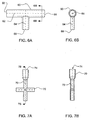
- FIGS. 6A and 6B show a T-shaped connector 60 having two passageways 62, 64 of different sizes, and end openings 66, 68 of different sizes.
- the different sizes allow differently-sized conduits and/or connectors to be attached to connector 60, and can provide different flow rates through connector 60.
- a connector can have more than two differently-sized passageways and/or end openings.
- FIGS. 7A and 7B show a cross-shaped connector 70 having a passageway 72 with a varying cross-sectional diameter or width.
- passageway 72 increases in diameter as it extends to end opening 74, for example, to attach to a larger sized conduit or connector.
- the change in diameter is smooth (e.g., without an abrupt step) to prevent material from accumulating in passageway 72.
- a passageway decreases in diameter or width as it extends to an end opening.
- a connector can have multiple passageways that vary in cross-sectional diameter or width.
- the conduits, connectors and polymeric members can be fabricated with materials having different colors, e.g., according to the desired color code.
- the different colors can facilitate assembly and inspection of the fluid transfer assembly, and confirmation that the assembly has been correctly configured, for example.
- fluid transfer assembly 20 is shown having connectors attached to conduits, in other embodiments, one or more connectors can be directly attached to one or more other connectors.
- Connectors having five or more (e.g., six, seven, eight, nine, ten or more) end openings can be formed; and/or connectors having four or more (e.g., five, six, seven, eight, nine, ten or more) passageways can be formed, according to fluid transfer assembly to be formed.
- the shape of a connector can be symmetrical or non-symmetrical.
- the connectors, conduits, and polymeric members can be the same or different, for example, in terms of size, chemical composition, shape, color, and configuration.
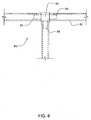
- Burst strength was tested using ASTM D-1599 "Standard Test Method for Resistance to Short-Time Hydraulic Pressure of Plastic Pipe, Tubing, and Fittings.” Results for burst tests using ASTM D1599 are provided for a) C-FLEX conduit alone (10" tubes); b) C-FLEX conduit and connectors in an overmolded T configuration with filled gaps as shown in FIG. 2B (Assembly A); and c) C-FLEX connectors and conduit joined by a standard internal T connector as shown in FIG. 8 (Assembly B). Although not shown in FIG. 8 , Assembly B was overmolded so that the entire assembly was encapsulated by a polymeric member beyond ends 83, 84 and 85 of internal T connector 82.
- Internal T connector 82 was of C-FLEX material having a Shorr A hardness of 95.
- the overmolded polymeric member was of C-FLEX, the same material from which the conduits and connectors were made. All testing was performed at 73 °F.
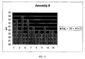
- Burst test results for the C-FLEX conduit alone are provided in graphical form in FIG. 9 . Seventeen samples were tested resulting in an Average Burst Pressure of 65 psi. Results for Assembly A are provided graphically in FIG. 10 and show an Average Burst Pressure of 62 psi. Results for Assembly B are provided graphically in FIG. 11 and show an Average Burst Pressure of 61 psi. Thus both Assembly A and Assembly B indicated a burst test pressure within 10% of the conduit absent any connector at all. A first burst strength is considered to be substantially equivalent to a second burst strength if it is within 10% of the value of the second burst strength. Assembly A, which had no internal T joining the three conduits together, provided a higher burst test pressure than did Assembly B. Assembly A, unlike Assembly B, had no regions with an inner diameter less than that of the conduits and/or connectors.
- Tensile strength was also evaluated for Assembly A and Assembly B.
- a modified version of ASTM D-412 was used in which opposed conduits on each assembly were gripped at a point 4 inches to either side of the connector and placed in a state of increasing tension until failure. The tension at which each sample failed was recorded. 24 samples of Assembly A and 25 samples of Assembly B were evaluated. Results for Assembly A show an average load at peak tension of 352 psi with a standard deviation of 16.7. Results for Assembly B show an average load at peak tension of 505.7 psi with a standard deviation of 27.0. Although the tension limits for Assembly A were below those for Assembly B, the values are still well above minimum limits for assemblies of this type.
Landscapes
- Engineering & Computer Science (AREA)
- Health & Medical Sciences (AREA)
- Heart & Thoracic Surgery (AREA)
- General Engineering & Computer Science (AREA)
- Mechanical Engineering (AREA)
- Public Health (AREA)
- Anesthesiology (AREA)
- Life Sciences & Earth Sciences (AREA)
- Animal Behavior & Ethology (AREA)
- General Health & Medical Sciences (AREA)
- Biomedical Technology (AREA)
- Veterinary Medicine (AREA)
- Hematology (AREA)
- Pulmonology (AREA)
- Manufacturing & Machinery (AREA)
- Rigid Pipes And Flexible Pipes (AREA)
- Infusion, Injection, And Reservoir Apparatuses (AREA)
- Physical Or Chemical Processes And Apparatus (AREA)
- Lining Or Joining Of Plastics Or The Like (AREA)
- Branch Pipes, Bends, And The Like (AREA)
Description
- The invention relates to fluid transfer assemblies, related methods, and methods for transferring fluids.
- Flexible polymer tubing can be used as conduits or flow paths to transfer fluid from a source to a desired destination. In some cases, as the fluid is transferred from the source to the destination, other material is added to the fluid. The fluid, with or without added material(s), can also be transferred (e.g., diverted) to multiple destinations such that the destinations have different compositions. As an example, in pharmaceutical manufacturing, a drug from a source can be transferred to a first destination through a flexible tubing. As the drug travels along the tubing, other ingredient(s) can be delivered through other fluidly-connected tubing to combine with the drug, and the resulting combination can be delivered to the first destination. The drug (with or without other ingredient(s)) can be delivered to other destinations by controlling the flow paths of the drug and the ingredient(s). The compositions in these other destinations may be different from or the same as the composition in the first destination.
US 4 070 044 A relates to a pipe connection which comprises two pipe ends, one inserted inside of the other, and one consisting essentially of crosslinked polymer material, whereas the other consists essentially of crosslinked or non-crosslinked polymer material, the connection having a layer of polymer material press-fitted and crosslinked between the two pipe ends.US 4 783 099 A relates to a conduit system for the flow of a fluid medium therethrough wherein the system is made up of a plurality of elongated conduit segments connected by means of fittings, such as straight connectors, elbows, T's or the like.JP H09 323357 A US 4 420 176 A relates to an elastomeric joint for use with couplings, pipe, connectors and the like. The elastomeric joint is particularly adapted to provide ease of mounting of the pipe, particularly plastic pipe, between couplings embedded in the floors in the construction of buildings. - The invention is as defined in the appended claims. Embodiments may include one or more of the following features.
- In one aspect, the invention features fluid transfer assemblies, related methods, and methods for transferring fluids (such those used in the medical industry or pharmaceutical industry). The assemblies and methods include a first connector attached to a conduit or a second connector by a polymeric member. The attached first connector and conduit or second connector are capable of providing a fluid transfer assembly that can be easily tailored and that has strong, fluid-tight connections.
- In another aspect, the invention features a method as defined in
claim 1 of attaching a first polymeric connector having a first passageway and a second passageway fixed relative to the first passageway, and a first polymeric conduit having a third passageway, the method comprising attaching the first polymeric connector to the first polymeric conduit with a first polymeric member extending over at least portions of outer surfaces of the first connector and the first conduit, the first passageway being in fluid communication with the third passageway. - In another aspect, an assembly as defined in
claim 7 is provided, the assembly comprising a first polymeric connector having a first passageway and a second passageway fixed relative to the first passageway, a first polymeric conduit having a third passageway in fluid communication with the first passageway, and a polymeric member extending over a gap between the first connector and the first conduit and at least portions of outer surfaces of the first connector and the first conduit. - Other aspects, features and advantages will be apparent from the description of the embodiments thereof and from the claims.
-
-
FIG. 1 is a schematic diagram of a fluid transfer assembly. -
FIG. 2A is a detailed view ofarea 2A inFIG. 1 ; andFIG. 2B is a cross-sectional view ofFIG. 2A . -
FIG. 3 is a side view of an embodiment of a connector connected to tubing. -
FIG. 4 is a side view of an embodiment of a connector connected to tubing. -
FIG. 5 is a side view of an embodiment of a connector connected to tubing. -
FIG. 6A is a side view of an embodiment of a connector; andFIG. 6B is an end view of the connector shown inFIG. 6A , taken alongline 6B-6B. -
FIG. 7A is a side view of an embodiment of a connector; andFIG. 7B is a cross-sectional view of the connector shown inFIG. 7A , taken alongline 7B-7B. -
FIG 8 is a side view of an embodiment of an assembly using an internal T connector. -
FIG 9 is a bar graph showing burst test results for tubing alone. -
FIG 10 is a bar graph showing burst test results for an embodiment of a connector connected to tubing. -
FIG 11 is a bar graph showing burst test results for another embodiment of a connector connected to tubing. -
FIG. 1 shows afluid transfer assembly 20 in which a fluid (e.g., a drug in a carrier) from asource 22 is transferred to adestination 24 through a series of conduits 26 (such as flexible polymeric tubing) andconnectors Connectors conduits 26 are attached in fluid communication with each other bypolymeric members 29 that, as shown, are in the shape of cylindrical collars. As the fluid travels throughassembly 20, additional materials fromsources other conduits 26 andconnectors destination 24. Referring also toFIGS. 2A, 2B ,3, 4 and 5 ,connectors shaped configuration 28 having three ends (FIGS. 2A and 2B ), a Y-shaped configuration 28'" having three ends (FIG. 3 ), an L-shaped configuration 28' having two ends (FIG. 4 ), and across-shaped configuration 28" (FIG. 5 ) having four ends. The various configurations of connectors allowfluid transfer assembly 20 to be tailored, for example, to fit within a desired space and/or to yield the desired final composition atdestination 24. Numerous configurations of fluid transfer assemblies can be formed by varying the number, type and location of connectors, conduits and material sources. For example, whileassembly 20 includes only onedestination 24, in other embodiments, the assembly includes multiple destinations that include different compositions and/or share the same composition. - Referring particularly to
FIG. 2B , connectors (as shown, T-shaped connector 28) are pre-formed polymeric pieces configured to place two or more passageways in fluid communication with each other. A passageway can be defined by a conduit or another connector. A connector includes apolymeric body 36 that defines afirst passageway 38 having a long axis L and at least oneother passageway 39 transversely fixed relative to the first passageway and having a long axis L'. As used herein, a passageway is a volume defined by portions whose long axes are substantially collinear. For example, T-shaped connector 28 includes twopassageways cross-shaped connector 28" includes two passageways that are fixed orthogonally relative to each other; and Y-shaped connector 28'" includes three passageways that are fixed relative to each other. In comparison, a flexible polymeric tube can have multiple passageways (e.g., when different portions of the tube are bent), but the passageways are not fixed relative to each other without a means of holding the portions in place. Along its long axis, the diameter or average width of a passageway can be substantially constant or different. The passageways can have a circular cross section or a non-circular cross section (e.g., oval, elliptical, irregularly or regularly polygonal, symmetrical, asymmetrical). - A connector further includes two or more end openings configured to be placed in fluid communication with an opening of a conduit or another connector. For example, T-shaped
connector 28 includes threeend openings 40; L-shaped connector 28' includes twoend openings 40;cross-shaped connector 28" includes fourend openings 40; and Y-shaped connector 28'" includes three openings. A connector may also be used to join two conduits axially together, end-to-end. The end openings, like the passageways, can have a circular cross section or a non-circular cross section (e.g., oval, elliptical, irregularly or regularly polygonal, symmetrical, asymmetrical). The diameter or average width of the end openings can be the same as or different from the diameter or average width of the passageway of a connector and/or a conduit attached to the connector. The assembly may be designed with no portion having an inner diameter that is less than that of the conduits used. Connectors can be formed, for example, by injection molding or cast molding. -
Conduits 26 can be any flexible body having a passageway that can be used to transport the desired fluid(s). An example of a conduit is an extruded flexible polymer tube having two end openings and one unfixed passageway between the openings. The size of conduit, such as its length and cross section, is not limited.Conduit 26 can include a single material or multiple materials (e.g., arranged in layers), as described inU.S. Patent Publication No. 2005/0043712 .Conduit 26 can have a circular cross section or a non-circular cross section (e.g., oval, elliptical, irregularly or regularly polygonal, symmetrical, asymmetrical). -
Connectors conduits 26 and polymeric members 29 (described below) can include (e.g., be formed of) a polymer or a combination of different polymers (e.g., copolymers, alloys, blends) used to transport the desired fluid(s), e.g., without adverse or unwanted reaction with the fluid(s). The compositions ofconnectors conduits 26 andpolymeric members 29 can be the same or different. In some embodiments, the compositions are selected based on their bonding properties so as to provide a strong, fluid-tight attachment. Examples of polymers include thermoplastics, thermosets, elastomers, thermoplastic elastomers, and engineering thermoplastic elastomers. Specific examples of polymers include polyureas, polyvinyls, polyvinyl chlorides (e.g., Tygon®), polypropylene, high density polyethylene, polyacrylics, copolymers and block copolymers thereof, such as block copolymers of polyether and polyamide, e.g., Pebax®, GRILON®, GRILAMID® (EMS), VESTAMID® (Creanova), C-Flex® thermoplastic elastomer (Consolidated Polymer Technologies, Inc.), EPDM, epichlorohydrin, nitrile butadiene elastomers, epoxies, isocyanates, polycaprolactone, poly(dimethylsiloxane) containing polyurethanes and ureas, polysiloxanes, polybutylene terephthalate-polyethene glycol block copolymers (e.g., HYTREL®), polyurethanes, copolymers such as ABS (acrylonitrile-butadiene-styrene), styrene-butylene-styrene, styrene-ethylene-butylene-styrene compounds having Shore A hardness of from approximately 5 to approximately 95, ABS/nylon, ABS/-polyvinyl chloride (PVC), ABS/polycarbonate, acrylonitrile copolymer, polyacrylamide, polyacrylate and polyacrylsulfone, polyesters such as polyethylene terephthalate (PET), polybutylene terephthalate (PBT), polyethylene naphthalate (PEN), liquid crystal polymer (LCP), polyester/polycaprolactone and polyester/polyadipate, polyethers including polyetheretherketone (PEEK), polyethersulfone (PES), polyetherimide (PEI), polyetherketone (PEK), polymethylpentene, polyphenylene ether, polyphenylene sulfide, styrene acrylonitrile (SAN), polyamides such as nylons, ethylene, propylene ethylene vinylacetate and ethylene vinyl alcohol (EVA), various ionomers, polyethylene type I-IV, polyolefins, polyurethane, polyvinyl chloride, and polysiloxanes (silicones), fluoropolymers such as polychlorotriethylene (CTFE), poly[ethylene-co-chlorotrifluoroethylene] (ECTFE) copolymer ethylene tetrafluoroethylene (ETFE), copolymer tetrafluoroethylene and hexafluoropropylene (FEP), perfluoroalkane (PFA) and poly[vinylidene fluoride] (PVDF), and mixtures thereof. Examples of nylons include aliphatic nylons (such as Nylon 11 (Elf Atochem), Nylon 6 (Allied Signal), Nylon 6/10 (BASF), Nylon 6/12 (Ashley Polymers) Nylon 12 and aromatic nylons (such as GRIVORY® (EMS)) and Nylon MXD-6. Other nylons and/or combinations of nylons can be used. - Connectors and/or conduits may include identification markings or other indicia that may be printed or stamped onto the component. Tags such as bar code tags or RFID tags may also be included.
- In some embodiments,
connectors conduits 26 and/orpolymeric members 29 further include one or more additives incorporated into the polymer(s). For example, one or more polymers can include one or more additives (such as nano-materials (e.g., nano-tubes, nano-clays, fibers) and liquid crystalline polymers) capable of enhancing the strength of the polymer(s). Other examples of additives include coupling or compatibilizing agents, radio-opacifiers (e.g., bismuth oxychloride or barium sulfate), dispersants, stabilizers, plasticizers, surfactants, and/or pigments. Examples of additives are described inU.S. Patent Application Publication Nos. 2003/0093107 and2005/0043712 . - Still referring to
FIG. 2B ,fluid transfer assembly 20 can be formed by attaching the connectors (as shown, connector 28) toconduits 26 usingpolymeric members 29 to provide a fluid-tight seal. In some embodiments,pre-formed connector 28 andconduit 26 are placed and aligned in an appropriately figured cavity suitable for injection molding. The end openings ofconnector 28 andconduit 26 can have the same cross-sectional configuration and size such that, when they are coaxially aligned, they provide a smooth and substantially seamless transition (see below). The entire inner surfaces ofconnector 28 andconduit 26, or only portions thereof, may be flush. In some embodiments,connector 28 andconduit 26 have the same inner width/diameter but different outer widths/diameters. In other embodiments,connector 28 andconduit 26 have different cross-sectional configuration and different inner and outer widths/diameters. An end ofconnector 28 and anend conduit 26 can be placed adjacent each other but not in contact so as to define agap 50. -
Polymeric member 29 can then be overmolded ontoconnector 28 andconduit 26 to form the assembly. More specifically, fluid material (prepolymer) forpolymeric member 29 is then injected into the cavity such that the fluid material flows intogap 50, extends over outer end portions ofconnector 28 andconduit 26, and thermally bonds with the connector and the conduit. Havinggap 50 and allowingpolymeric member 29 to extend into the gap provide increased surface area (e.g., relative to having no gap) for bonding with the end walls ofconnector 28 andconduit 26, and a strong attachment among the connector, the conduit and the polymeric member.Polymeric member 29 does not extend into the passageways ofconnector 28 orconduit 26 such that there is there is a substantially smooth, seamless transition between the connector and the conduit. Having a substantially seamless transition betweenconnector 28 and conduit 26 (e.g., without a protrusion extending radially inward fromgap 50 intopassageway 38, or a recess extending into the gap) prevents material from accumulating influid transfer assembly 20. In some embodiments, the protrusion or recess is less than approximately one mm. A seamless transition means that there is an absence of, or very few, visible craters, creases or seams at the transition and that the union is continuous and complete. As an example, to attach a ⅛ in I.D. x ¼ in O.D. connector made of C-Flex® to a ⅛ in I.D. x ¼ in O.D. flexible tubing made of C-Flex®, the gap between the ends of the connector and the tubing is approximately 3 mm, and the polymeric member extends approximately 3 mm from the ends of the connector and the tubing for a total collar length of about 9 mm. The above injection molded process can be repeated to form the desired fluid transfer assembly. - Connectors may also include inserts such as rods or pins that may be placed within the lumen of the connector and/or conduit when
polymeric member 29 is to be molded. The insert may be removed from the assembly after the molding has been completed. An insert can limit the flow of liquid polymer so that it does not extend inside the inner diameter of the connector and/or conduit. Thus, a rod that has a diameter similar to the ID of the conduit and connector can help to form a smooth inner wall of constant diameter when a gap between the conduit and connector is filled. This smooth, constant diameter transition can result in better flow, more predictable mixing, and easier cleaning and disinfection. Constant ID conduits and connectors can also facilitate easier and more accurate calculations of fluid flow patterns throughout the system. - After the fluid material for
polymeric member 29 solidifies, the assembly of connector, conduit and polymeric member is capable of having a tensile strength and/or burst strength substantially equal (e.g., within approximately 10%) to that of the conduit itself. - The polymeric members in a specific assembly can be molded individually in a sequential process or can be molded together in a single step. For example, referring to
FIG. 2B ,polymeric members 29 can be molded one at a time or simultaneously. - In the first instance, a mold can be designed to receive one branch of connector 28 (passageway 38) and one end of
conduit 26. Each component is axially aligned and spaced properly to provide a desired gap between the ends. An insert may be used to align the components and/or to limit intrusion of prepolymer into the gap.Polymeric member 29 is then overmolded in place. The mold is removed,connector 28 is rotated, and the process is repeated with a second branch (passageway 39) and asecond conduit 26. Finally, the process can be repeated with the third branch of the T. The same mold may be used for each polymeric member. - In the second instance, two or more connectors in a single assembly can be molded simultaneously using a single mold. For instance, if the T of
FIG. 2B is to be overmolded,connector 28 can be placed in a mold and each of the threeconduits 26 can then be aligned with the corresponding passages on the connector. Appropriate inserts may be used. The mold can be designed so that a single injection can provide prepolymer to each of the threepolymeric members 29 that are to be overmolded. Thus, in a single step, each of the three polymeric members can be molded, providing for an increased rate of production. Molds may be designed to match the geometry of a specific assembly. Molds may also include inserts that can be optionally used to block flow of prepolymer to a specific site. Therefore, a single mold can be used to produce two different assemblies such as the assembly ofFIG. 2B and the assembly ofFIG. 5 . The cross-shaped assembly ofFIG. 5 can be produced in a mold that injects prepolymer to each of the four connection sites. The same mold can be used to produce the T assembly ofFIG. 2B by using an insert or other blocking device to prevent the flow of prepolymer to the fourth site that is not present in the T assembly. - While a number of embodiments have been described, the invention is not so limited.
- For example,
FIGS. 6A and 6B show a T-shapedconnector 60 having twopassageways openings connector 60, and can provide different flow rates throughconnector 60. In other embodiments, a connector can have more than two differently-sized passageways and/or end openings. - As another example,
FIGS. 7A and 7B show across-shaped connector 70 having apassageway 72 with a varying cross-sectional diameter or width. As shown,passageway 72 increases in diameter as it extends to endopening 74, for example, to attach to a larger sized conduit or connector. The change in diameter is smooth (e.g., without an abrupt step) to prevent material from accumulating inpassageway 72. In other embodiments, a passageway decreases in diameter or width as it extends to an end opening. A connector can have multiple passageways that vary in cross-sectional diameter or width. - In some embodiments, the conduits, connectors and polymeric members can be fabricated with materials having different colors, e.g., according to the desired color code. The different colors can facilitate assembly and inspection of the fluid transfer assembly, and confirmation that the assembly has been correctly configured, for example.
- While
fluid transfer assembly 20 is shown having connectors attached to conduits, in other embodiments, one or more connectors can be directly attached to one or more other connectors. - Connectors having five or more (e.g., six, seven, eight, nine, ten or more) end openings can be formed; and/or connectors having four or more (e.g., five, six, seven, eight, nine, ten or more) passageways can be formed, according to fluid transfer assembly to be formed. The shape of a connector can be symmetrical or non-symmetrical.
- Within a fluid transfer assembly, the connectors, conduits, and polymeric members can be the same or different, for example, in terms of size, chemical composition, shape, color, and configuration.
- Burst strength was tested using ASTM D-1599 "Standard Test Method for Resistance to Short-Time Hydraulic Pressure of Plastic Pipe, Tubing, and Fittings." Results for burst tests using ASTM D1599 are provided for a) C-FLEX conduit alone (10" tubes); b) C-FLEX conduit and connectors in an overmolded T configuration with filled gaps as shown in
FIG. 2B (Assembly A); and c) C-FLEX connectors and conduit joined by a standard internal T connector as shown inFIG. 8 (Assembly B). Although not shown inFIG. 8 , Assembly B was overmolded so that the entire assembly was encapsulated by a polymeric member beyond ends 83, 84 and 85 ofinternal T connector 82.Internal T connector 82 was of C-FLEX material having a Shorr A hardness of 95. In both Assembly A and Assembly B the overmolded polymeric member was of C-FLEX, the same material from which the conduits and connectors were made. All testing was performed at 73 °F. - Burst test results for the C-FLEX conduit alone are provided in graphical form in
FIG. 9 . Seventeen samples were tested resulting in an Average Burst Pressure of 65 psi. Results for Assembly A are provided graphically inFIG. 10 and show an Average Burst Pressure of 62 psi. Results for Assembly B are provided graphically inFIG. 11 and show an Average Burst Pressure of 61 psi. Thus both Assembly A and Assembly B indicated a burst test pressure within 10% of the conduit absent any connector at all. A first burst strength is considered to be substantially equivalent to a second burst strength if it is within 10% of the value of the second burst strength. Assembly A, which had no internal T joining the three conduits together, provided a higher burst test pressure than did Assembly B. Assembly A, unlike Assembly B, had no regions with an inner diameter less than that of the conduits and/or connectors. - Tensile strength was also evaluated for Assembly A and Assembly B. A modified version of ASTM D-412 was used in which opposed conduits on each assembly were gripped at a point 4 inches to either side of the connector and placed in a state of increasing tension until failure. The tension at which each sample failed was recorded. 24 samples of Assembly A and 25 samples of Assembly B were evaluated. Results for Assembly A show an average load at peak tension of 352 psi with a standard deviation of 16.7. Results for Assembly B show an average load at peak tension of 505.7 psi with a standard deviation of 27.0. Although the tension limits for Assembly A were below those for Assembly B, the values are still well above minimum limits for assemblies of this type.
- As the tensile strength test was performed on tubing and connectors, an additional nine samples of Assembly A and nine samples of Assembly B were tested and the force (without regard to a specific area of the tubing) required for the assembly to fail was recorded. For Assembly A the average force at failure was 402.4 N with a standard deviation of 23.9. Eight of the Assembly A samples failed at the junction of the tube and the T connection while one failed in the middle of the T. For Assembly B, the average force at failure was 511.4 N with a standard deviation of 28.7. Four of these samples failed at the junction of the tubing and the connector, four failed at the tubing about 1 cm from the junction and one failed at the grip. Although Assembly A results were about 20% below those of Assembly B, the values were still well above threshold levels for fluid distribution systems of this type.
Claims (10)
- A method of attaching a first polymeric connector (28) having a first passageway (38) and a second passageway (39) fixed relative to the first passageway, and a first flexible polymeric conduit (26) having a third passageway, the method comprising:attaching the first polymeric connector (28) to the first flexible polymeric conduit (26) with a first polymeric member (29) extending over at least portions of outer surfaces of the first connector (28) and the first conduit (26), the first passageway (38) being in fluid communication with the third passageway,characterized in that the first polymeric member (29) extends into a gap (50) defined between ends of the first polymeric connector (28) and the first polymeric conduit (26),wherein:the polymeric member (29) does not extend into the passageways (38, 39) of the first polymeric connector (28) or the first flexible polymeric conduit (26) such that there is a substantially smooth, seamless transition between the first polymeric connector (28) and the first flexible polymeric conduit (26); andthe first flexible polymeric conduit (26) includes an elastomer, a thermoplastic elastomer, an engineering thermoplastic elastomer, or any combination thereof.
- The method of claim 1, wherein the first polymeric connector (28) and the first flexible polymeric conduit (26) have inner widths or diameters that are substantially the same.
- The method of claim 1, wherein at least portions of the first (38) and third passageways are substantially flush.
- The method of any of claims 1-3, wherein the first connector (28) comprises three or more end openings (40).
- The method of any of claims 1-4, comprising injection molding the first polymeric member (29).
- The method of any of claims 1-3, wherein the first polymeric connector (28), the first flexible polymeric conduit (26), and the first polymeric member (29) comprise one or more thermoplastic elastomers.
- An assembly, comprising:a first polymeric connector (28) having a first passageway (38) and a second passageway (38) fixed relative to the first passageway (38);a first flexible polymeric conduit (26) having a third passageway in fluid communication with the first passageway (38); anda polymeric member (29) extending into a gap (50) defined between ends of the first polymeric connector (28) and the first flexible polymeric conduit (26) and extending over the gap (50) between the first connector (28) and the first conduit (26) and at least portions of outer surfaces of the first connector (28) and the first conduit (26),wherein:the polymeric member (29) does not extend into the passageways (38, 39) of the first polymeric connector (28) or the first flexible polymeric conduit (26) such that there is a substantially smooth, seamless transition between the first polymeric connector (28) and the first flexible polymeric conduit (26); andthe first flexible polymeric conduit (26) includes an elastomer, a thermoplastic elastomer, an engineering thermoplastic elastomer, or any combination thereof.
- The assembly of claim 7, wherein the first polymeric connector (28) and the first flexible polymeric conduit (26) have inner widths or diameters that are substantially the same.
- The assembly of claim 7, wherein at least portions of the first (38) and third passageways are substantially flush.
- The assembly of claim 7, wherein the first connector (28) comprises three or more end openings (40).
Applications Claiming Priority (2)
| Application Number | Priority Date | Filing Date | Title |
|---|---|---|---|
| US3749008P | 2008-03-18 | 2008-03-18 | |
| PCT/US2009/001519 WO2009117059A2 (en) | 2008-03-18 | 2009-03-10 | Fluid transfer assemblies and related methods |
Publications (3)
| Publication Number | Publication Date |
|---|---|
| EP2274044A2 EP2274044A2 (en) | 2011-01-19 |
| EP2274044A4 EP2274044A4 (en) | 2014-07-09 |
| EP2274044B1 true EP2274044B1 (en) | 2016-11-16 |
Family
ID=41091438
Family Applications (1)
| Application Number | Title | Priority Date | Filing Date |
|---|---|---|---|
| EP09722716.9A Active EP2274044B1 (en) | 2008-03-18 | 2009-03-10 | Fluid transfer assemblies and related methods |
Country Status (7)
| Country | Link |
|---|---|
| US (1) | US9259563B2 (en) |
| EP (1) | EP2274044B1 (en) |
| JP (1) | JP2011515635A (en) |
| KR (1) | KR101292797B1 (en) |
| CN (1) | CN101977653B (en) |
| BR (1) | BRPI0910925B8 (en) |
| WO (1) | WO2009117059A2 (en) |
Families Citing this family (43)
| Publication number | Priority date | Publication date | Assignee | Title |
|---|---|---|---|---|
| ES2418357T3 (en) * | 2005-10-21 | 2013-08-13 | Dow Corning Corporation | Fluid transfer set |
| WO2012096969A1 (en) * | 2011-01-10 | 2012-07-19 | Colder Products Company | Biodegradable fluid delivery device |
| DK2723647T3 (en) | 2011-06-22 | 2018-07-23 | Sartorius Stedim North America Inc | Container closures and methods of use and manufacture thereof |
| US10773863B2 (en) | 2011-06-22 | 2020-09-15 | Sartorius Stedim North America Inc. | Vessel closures and methods for using and manufacturing same |
| US9376305B2 (en) | 2011-06-22 | 2016-06-28 | Allpure Technologies, Inc. | Fluid transfer interface |
| JP6147970B2 (en) * | 2011-09-12 | 2017-06-14 | カナフレックスコーポレーション株式会社 | Branch connection method |
| JPWO2013073540A1 (en) * | 2011-11-17 | 2015-04-02 | 日本電気株式会社 | Piping connection structure and piping connection method |
| US20130199530A1 (en) * | 2012-02-02 | 2013-08-08 | Gina Burger | Y connector/adapter allowing connection of two standard oxygen supply tank inlet tubes to feed to single standard size outlet tube |
| EP3077324A4 (en) | 2013-12-06 | 2017-08-02 | Allpure Technologies, Inc. | Fluid transfer interface |
| DE102014216329A1 (en) | 2014-08-18 | 2016-02-18 | Raumedic Ag | A method for producing a fluid-tight connection between at least two fluid-carrying silicone hose components and fluid guide assembly produced by this method |
| TW201619539A (en) * | 2014-11-21 | 2016-06-01 | 聖高拜塑膠製品公司 | Fluid transfer assembly |
| WO2016109805A1 (en) | 2014-12-31 | 2016-07-07 | Saint-Gobain Performance Plastics Corporation | Molded fluid transfer assemblies having increased working pressures and burst pressures |
| JP6956158B2 (en) * | 2015-09-29 | 2021-10-27 | ミライアル株式会社 | Plumbing |
| JPWO2017056203A1 (en) * | 2015-09-29 | 2018-07-12 | ミライアル株式会社 | Resin pipe fittings |
| US10738900B2 (en) * | 2015-10-01 | 2020-08-11 | Alphinity, Llc | Valve assembly with directional flow path |
| KR20180071352A (en) * | 2015-10-28 | 2018-06-27 | 미라이얼 가부시키가이샤 | Resin pipe joint, piping, and pipe manufacturing method |
| EP3595861B1 (en) | 2017-03-17 | 2022-08-17 | Saint-Gobain Performance Plastics Corporation | Method of making a fluid manifold |
| US9975753B1 (en) | 2017-04-26 | 2018-05-22 | Sartorius Stedim North America Inc. | Detachable fluid transfer device accessory and a fluid transfer assembly |
| US10649472B2 (en) | 2017-07-10 | 2020-05-12 | Tse Industries, Inc. | Tubing system |
| US11691866B2 (en) | 2017-11-14 | 2023-07-04 | Sartorius Stedim North America Inc. | System for simultaneous distribution of fluid to multiple vessels and method of using the same |
| EP3710361A4 (en) | 2017-11-14 | 2021-08-11 | Sartorius Stedim North America Inc. | FLUID TRANSFER KIT WITH A JUNCTION HAVING MULTIPLE FLUID WAYS |
| US12252391B2 (en) | 2017-11-14 | 2025-03-18 | Sartorius Stedim North America Inc. | System for simultaneous distribution of fluid to multiple vessels and method of using the same |
| US11319201B2 (en) | 2019-07-23 | 2022-05-03 | Sartorius Stedim North America Inc. | System for simultaneous filling of multiple containers |
| US11577953B2 (en) | 2017-11-14 | 2023-02-14 | Sartorius Stedim North America, Inc. | System for simultaneous distribution of fluid to multiple vessels and method of using the same |
| EP3608092B1 (en) | 2018-08-10 | 2023-06-28 | Crompton Technology Group Limited | Composite connector and method of manufacturing the same |
| EP3608093B1 (en) | 2018-08-10 | 2024-04-17 | Crompton Technology Group Limited | Composite connector and method of manufacturing the same |
| EP3608089B1 (en) | 2018-08-10 | 2022-10-12 | Crompton Technology Group Limited | Composite connector and method of manufacturing the same |
| EP3608095B1 (en) * | 2018-08-10 | 2026-05-06 | Crompton Technology Group Limited | Composite connectors and methods of manufacturing the same |
| EP3608091B1 (en) | 2018-08-10 | 2025-10-01 | Crompton Technology Group Limited | Composite connector and method of manufacturing the same |
| EP3608094B1 (en) | 2018-08-10 | 2024-09-25 | Crompton Technology Group Limited | Composite connector and method of manufacturing the same |
| CN114765964A (en) * | 2019-11-04 | 2022-07-19 | 帕克-汉尼芬公司 | Line mixer device, mixing method and method for manufacturing line mixer device |
| US12324895B2 (en) | 2019-11-08 | 2025-06-10 | Global Life Sciences Solutions Usa Llc | Sparger device for a bioprocessing system and method of manufacturing a sparger device |
| US20240093815A1 (en) * | 2020-11-10 | 2024-03-21 | Composite Fluid Transfer LLC | Universal high-pressure fittings for composite pipes |
| WO2022103508A1 (en) * | 2020-11-10 | 2022-05-19 | Composite Fluid Transfer LLC | Universal high-pressure fittings for composite pipes |
| WO2022235689A1 (en) * | 2021-05-05 | 2022-11-10 | Carefusion 303, Inc. | Overmolded connectors for tubing |
| US12239127B2 (en) | 2021-07-28 | 2025-03-04 | Sartorius Stedim North America Inc. | Thermal capacitors, systems, and methods for rapid freezing or heating of biological materials |
| EP4426961A4 (en) * | 2021-11-01 | 2025-08-06 | Entegris Inc | Overmolded connectors and methods for producing the same |
| DE102022200748A1 (en) | 2022-01-24 | 2023-07-27 | Raumedic Ag | Method for connecting two silicone hose sections and pharmaceutical media transfer method with such a connecting method and device for carrying out the method |
| DE102023205431A1 (en) | 2023-06-12 | 2024-12-12 | Raumedic Ag | Device for connecting two silicone hose sections in a pharmaceutical media transfer process |
| DE102023205432A1 (en) | 2023-06-12 | 2024-12-12 | Raumedic Ag | Method for connecting two hose sections, hose assembly connected using the method, method for closing a hose section and hose assembly manufactured using the closing method |
| DE102023205430A1 (en) | 2023-06-12 | 2024-12-12 | Raumedic Ag | Method for connecting two hose sections, hose assembly connected using the method, method for closing a hose section and hose assembly manufactured using the closing method |
| NL2035106B1 (en) * | 2023-06-15 | 2024-12-20 | Nx Filtration N V | Tubular connecting member for a membrane filtration system |
| DE102023206594A1 (en) | 2023-07-11 | 2025-01-16 | Raumedic Ag | Device for connecting two silicone hose sections in a pharmaceutical media transfer process |
Citations (1)
| Publication number | Priority date | Publication date | Assignee | Title |
|---|---|---|---|---|
| US4420176A (en) * | 1981-05-27 | 1983-12-13 | Cornwall Kenneth R | Elastomeric joint for use between rigid fittings and rigid pipe and method of use |
Family Cites Families (34)
| Publication number | Priority date | Publication date | Assignee | Title |
|---|---|---|---|---|
| US176A (en) * | 1837-04-20 | Samuel rust | ||
| US1365025A (en) | 1918-11-13 | 1921-01-11 | Elder John | Pipe-coupling |
| US2009068A (en) * | 1934-06-08 | 1935-07-23 | Harry W Porter | Underground conduit |
| US2739829A (en) * | 1950-08-05 | 1956-03-27 | American Viscose Corp | Plastic pipe joint |
| US2706134A (en) * | 1951-11-19 | 1955-04-12 | Ross B Wilson | Embedded sprinkler system |
| US3826521A (en) * | 1972-10-30 | 1974-07-30 | P Wilhelmsen | Glued replacement unit for repairing ruptured pipe |
| US4070044A (en) | 1976-01-22 | 1978-01-24 | Phillips Petroleum Company | Polymer pipe connection and method to make it |
| US4396046A (en) * | 1981-08-19 | 1983-08-02 | Amtel, Inc. | Buoy-to-yoke coupling system |
| NL8303190A (en) * | 1983-09-15 | 1985-04-01 | Wavin Bv | TUBE CONNECTION OF FIBER-REINFORCED PLASTIC TUBES. |
| USH176H (en) * | 1985-08-16 | 1986-12-02 | At&T Bell Laboratories | Slip tee pipe fitting |
| CA1219228A (en) | 1985-12-17 | 1987-03-17 | Oscar P. Muser | Fluid flow conduit systems |
| JP2547428B2 (en) * | 1987-11-25 | 1996-10-23 | 大東電材株式会社 | Method for manufacturing connection part of branch pipe guard with different diameter pipe |
| JPH048535A (en) | 1990-04-26 | 1992-01-13 | Asahi Organic Chem Ind Co Ltd | Joining of plastic pipes |
| JPH04290712A (en) * | 1991-03-20 | 1992-10-15 | Toyoda Gosei Co Ltd | Covering layer-molding method |
| JP2699222B2 (en) | 1991-04-18 | 1998-01-19 | 旭有機材工業株式会社 | Plastic tube fusion method |
| US5356587A (en) | 1991-10-14 | 1994-10-18 | Toyoda Gosei Co., Ltd. | Process for producing hose having connecting portion |
| JPH0596646A (en) | 1991-10-14 | 1993-04-20 | Toyoda Gosei Co Ltd | Manufacture of hose with junction |
| US5248172A (en) * | 1992-03-31 | 1993-09-28 | United States Of America As Represented By The Secretary Of The Army | Adjustable fluid transfer apparatus |
| JPH09229284A (en) | 1996-02-27 | 1997-09-05 | Kunimori Kagaku:Kk | Pipe fittings |
| JPH09323357A (en) * | 1996-06-06 | 1997-12-16 | Sekisui Chem Co Ltd | Method and apparatus for connecting thermoplastic resin pipes |
| JPH116595A (en) | 1997-06-19 | 1999-01-12 | Sekisui Chem Co Ltd | Pipe fittings |
| US6290265B1 (en) | 1997-08-11 | 2001-09-18 | Saint-Gobain Performance Plastics Corporation | Tubing and connector assembly and method and molding |
| CN2350964Y (en) * | 1998-11-23 | 1999-12-01 | 湖南省资兴矿务局设计研究院 | Seeping watering arrangement |
| US6270125B1 (en) * | 1999-10-06 | 2001-08-07 | Mercury Plastics, Inc. | Molded tubing assemblies |
| US6318761B1 (en) * | 1999-11-26 | 2001-11-20 | Duane D. Robertson | Replacement fitting for rigid, plastic pipes |
| JP4968496B2 (en) | 2001-07-25 | 2012-07-04 | 株式会社ニックス | Hot water fittings |
| EP1429833B1 (en) | 2001-09-28 | 2018-02-14 | Boston Scientific Limited | Catheter comprising nanocomposites |
| CN2557784Y (en) * | 2002-05-15 | 2003-06-25 | 河北省电焊机股份有限公司 | High-strength corrosion-resistant, wearing-resistant pipe line |
| US20030233074A1 (en) * | 2002-06-17 | 2003-12-18 | Shields Jack W. | IV access connectors for syringes with needles |
| JP2004100767A (en) | 2002-09-06 | 2004-04-02 | Flowell Corp | Joint structure of resin tube |
| US7166099B2 (en) | 2003-08-21 | 2007-01-23 | Boston Scientific Scimed, Inc. | Multilayer medical devices |
| US8210166B2 (en) * | 2003-12-16 | 2012-07-03 | Wolfe Tory Medical, Inc. | Vial multi-access adapter |
| US7708923B1 (en) | 2004-02-19 | 2010-05-04 | Saint-Gobain Performance Plastics Corporation | Process of molding a coupling for interconnecting tubes |
| KR20090010019A (en) | 2005-10-05 | 2009-01-28 | 아큐 레이트 피이티와이 리미티이드 | Flow Control Dosing Set |
-
2009
- 2009-03-10 KR KR1020107022424A patent/KR101292797B1/en not_active Expired - Fee Related
- 2009-03-10 WO PCT/US2009/001519 patent/WO2009117059A2/en not_active Ceased
- 2009-03-10 CN CN200980109430.4A patent/CN101977653B/en active Active
- 2009-03-10 EP EP09722716.9A patent/EP2274044B1/en active Active
- 2009-03-10 BR BRPI0910925A patent/BRPI0910925B8/en active IP Right Grant
- 2009-03-10 JP JP2011500786A patent/JP2011515635A/en active Pending
- 2009-03-18 US US12/406,590 patent/US9259563B2/en active Active
Patent Citations (1)
| Publication number | Priority date | Publication date | Assignee | Title |
|---|---|---|---|---|
| US4420176A (en) * | 1981-05-27 | 1983-12-13 | Cornwall Kenneth R | Elastomeric joint for use between rigid fittings and rigid pipe and method of use |
Also Published As
| Publication number | Publication date |
|---|---|
| BRPI0910925B8 (en) | 2021-06-22 |
| CN101977653B (en) | 2014-08-13 |
| EP2274044A4 (en) | 2014-07-09 |
| BRPI0910925B1 (en) | 2019-12-03 |
| US20090243284A1 (en) | 2009-10-01 |
| CN101977653A (en) | 2011-02-16 |
| US9259563B2 (en) | 2016-02-16 |
| WO2009117059A2 (en) | 2009-09-24 |
| BRPI0910925A8 (en) | 2019-01-29 |
| BRPI0910925A2 (en) | 2018-03-27 |
| EP2274044A2 (en) | 2011-01-19 |
| WO2009117059A3 (en) | 2009-11-12 |
| KR20100124314A (en) | 2010-11-26 |
| KR101292797B1 (en) | 2013-08-02 |
| JP2011515635A (en) | 2011-05-19 |
Similar Documents
| Publication | Publication Date | Title |
|---|---|---|
| US9259563B2 (en) | Fluid transfer assemblies and related methods | |
| JP6346613B2 (en) | Overmolded medical connector tubing and method | |
| EP2383502B1 (en) | Fluid transfer assembly | |
| CN107110412B (en) | Molded fluid delivery assemblies with increased working and burst pressures | |
| CA2753707C (en) | Coupling assembly for connection to a hose | |
| US20090021002A1 (en) | Fluid line coupling | |
| CN114734647A (en) | Compression collar for coupling pipe to fitting and method of use | |
| EP2678599B1 (en) | Fusion welding socket | |
| CN116293113A (en) | Fluid delivery coupling | |
| US20230140392A1 (en) | Overmolded connectors and methods of making the same | |
| CN107875506A (en) | Medical apparatus and infusion set | |
| HK1211880B (en) | Overmolded medical connector tubing and method |
Legal Events
| Date | Code | Title | Description |
|---|---|---|---|
| PUAI | Public reference made under article 153(3) epc to a published international application that has entered the european phase |
Free format text: ORIGINAL CODE: 0009012 |
|
| 17P | Request for examination filed |
Effective date: 20101011 |
|
| AK | Designated contracting states |
Kind code of ref document: A2 Designated state(s): AT BE BG CH CY CZ DE DK EE ES FI FR GB GR HR HU IE IS IT LI LT LU LV MC MK MT NL NO PL PT RO SE SI SK TR |
|
| AX | Request for extension of the european patent |
Extension state: AL BA RS |
|
| DAX | Request for extension of the european patent (deleted) | ||
| A4 | Supplementary search report drawn up and despatched |
Effective date: 20140605 |
|
| RIC1 | Information provided on ipc code assigned before grant |
Ipc: A61M 37/00 20060101ALI20140530BHEP Ipc: A61M 39/02 20060101ALI20140530BHEP Ipc: A61M 5/00 20060101ALI20140530BHEP Ipc: A61M 39/10 20060101AFI20140530BHEP |
|
| 17Q | First examination report despatched |
Effective date: 20150721 |
|
| GRAP | Despatch of communication of intention to grant a patent |
Free format text: ORIGINAL CODE: EPIDOSNIGR1 |
|
| INTG | Intention to grant announced |
Effective date: 20160603 |
|
| RIN1 | Information on inventor provided before grant (corrected) |
Inventor name: STADT, GERALD, L. Inventor name: KLINGEL, ROBERT, R., JR. |
|
| GRAS | Grant fee paid |
Free format text: ORIGINAL CODE: EPIDOSNIGR3 |
|
| RAP1 | Party data changed (applicant data changed or rights of an application transferred) |
Owner name: SAINT-GOBAIN PERFORMANCE PLASTICS CORPORATION |
|
| GRAA | (expected) grant |
Free format text: ORIGINAL CODE: 0009210 |
|
| AK | Designated contracting states |
Kind code of ref document: B1 Designated state(s): AT BE BG CH CY CZ DE DK EE ES FI FR GB GR HR HU IE IS IT LI LT LU LV MC MK MT NL NO PL PT RO SE SI SK TR |
|
| REG | Reference to a national code |
Ref country code: GB Ref legal event code: FG4D |
|
| REG | Reference to a national code |
Ref country code: CH Ref legal event code: EP |
|
| REG | Reference to a national code |
Ref country code: IE Ref legal event code: FG4D |
|
| REG | Reference to a national code |
Ref country code: AT Ref legal event code: REF Ref document number: 845342 Country of ref document: AT Kind code of ref document: T Effective date: 20161215 |
|
| REG | Reference to a national code |
Ref country code: DE Ref legal event code: R096 Ref document number: 602009042433 Country of ref document: DE |
|
| REG | Reference to a national code |
Ref country code: FR Ref legal event code: PLFP Year of fee payment: 9 |
|
| PG25 | Lapsed in a contracting state [announced via postgrant information from national office to epo] |
Ref country code: LV Free format text: LAPSE BECAUSE OF FAILURE TO SUBMIT A TRANSLATION OF THE DESCRIPTION OR TO PAY THE FEE WITHIN THE PRESCRIBED TIME-LIMIT Effective date: 20161116 |
|
| REG | Reference to a national code |
Ref country code: NL Ref legal event code: MP Effective date: 20161116 |
|
| REG | Reference to a national code |
Ref country code: LT Ref legal event code: MG4D |
|
| REG | Reference to a national code |
Ref country code: AT Ref legal event code: MK05 Ref document number: 845342 Country of ref document: AT Kind code of ref document: T Effective date: 20161116 |
|
| PG25 | Lapsed in a contracting state [announced via postgrant information from national office to epo] |
Ref country code: NL Free format text: LAPSE BECAUSE OF FAILURE TO SUBMIT A TRANSLATION OF THE DESCRIPTION OR TO PAY THE FEE WITHIN THE PRESCRIBED TIME-LIMIT Effective date: 20161116 Ref country code: NO Free format text: LAPSE BECAUSE OF FAILURE TO SUBMIT A TRANSLATION OF THE DESCRIPTION OR TO PAY THE FEE WITHIN THE PRESCRIBED TIME-LIMIT Effective date: 20170216 Ref country code: GR Free format text: LAPSE BECAUSE OF FAILURE TO SUBMIT A TRANSLATION OF THE DESCRIPTION OR TO PAY THE FEE WITHIN THE PRESCRIBED TIME-LIMIT Effective date: 20170217 Ref country code: LT Free format text: LAPSE BECAUSE OF FAILURE TO SUBMIT A TRANSLATION OF THE DESCRIPTION OR TO PAY THE FEE WITHIN THE PRESCRIBED TIME-LIMIT Effective date: 20161116 Ref country code: SE Free format text: LAPSE BECAUSE OF FAILURE TO SUBMIT A TRANSLATION OF THE DESCRIPTION OR TO PAY THE FEE WITHIN THE PRESCRIBED TIME-LIMIT Effective date: 20161116 |
|
| PG25 | Lapsed in a contracting state [announced via postgrant information from national office to epo] |
Ref country code: AT Free format text: LAPSE BECAUSE OF FAILURE TO SUBMIT A TRANSLATION OF THE DESCRIPTION OR TO PAY THE FEE WITHIN THE PRESCRIBED TIME-LIMIT Effective date: 20161116 Ref country code: PT Free format text: LAPSE BECAUSE OF FAILURE TO SUBMIT A TRANSLATION OF THE DESCRIPTION OR TO PAY THE FEE WITHIN THE PRESCRIBED TIME-LIMIT Effective date: 20170316 Ref country code: PL Free format text: LAPSE BECAUSE OF FAILURE TO SUBMIT A TRANSLATION OF THE DESCRIPTION OR TO PAY THE FEE WITHIN THE PRESCRIBED TIME-LIMIT Effective date: 20161116 Ref country code: ES Free format text: LAPSE BECAUSE OF FAILURE TO SUBMIT A TRANSLATION OF THE DESCRIPTION OR TO PAY THE FEE WITHIN THE PRESCRIBED TIME-LIMIT Effective date: 20161116 Ref country code: FI Free format text: LAPSE BECAUSE OF FAILURE TO SUBMIT A TRANSLATION OF THE DESCRIPTION OR TO PAY THE FEE WITHIN THE PRESCRIBED TIME-LIMIT Effective date: 20161116 Ref country code: HR Free format text: LAPSE BECAUSE OF FAILURE TO SUBMIT A TRANSLATION OF THE DESCRIPTION OR TO PAY THE FEE WITHIN THE PRESCRIBED TIME-LIMIT Effective date: 20161116 |
|
| PG25 | Lapsed in a contracting state [announced via postgrant information from national office to epo] |
Ref country code: CZ Free format text: LAPSE BECAUSE OF FAILURE TO SUBMIT A TRANSLATION OF THE DESCRIPTION OR TO PAY THE FEE WITHIN THE PRESCRIBED TIME-LIMIT Effective date: 20161116 Ref country code: RO Free format text: LAPSE BECAUSE OF FAILURE TO SUBMIT A TRANSLATION OF THE DESCRIPTION OR TO PAY THE FEE WITHIN THE PRESCRIBED TIME-LIMIT Effective date: 20161116 Ref country code: SK Free format text: LAPSE BECAUSE OF FAILURE TO SUBMIT A TRANSLATION OF THE DESCRIPTION OR TO PAY THE FEE WITHIN THE PRESCRIBED TIME-LIMIT Effective date: 20161116 Ref country code: DK Free format text: LAPSE BECAUSE OF FAILURE TO SUBMIT A TRANSLATION OF THE DESCRIPTION OR TO PAY THE FEE WITHIN THE PRESCRIBED TIME-LIMIT Effective date: 20161116 Ref country code: EE Free format text: LAPSE BECAUSE OF FAILURE TO SUBMIT A TRANSLATION OF THE DESCRIPTION OR TO PAY THE FEE WITHIN THE PRESCRIBED TIME-LIMIT Effective date: 20161116 |
|
| REG | Reference to a national code |
Ref country code: DE Ref legal event code: R097 Ref document number: 602009042433 Country of ref document: DE |
|
| PG25 | Lapsed in a contracting state [announced via postgrant information from national office to epo] |
Ref country code: IT Free format text: LAPSE BECAUSE OF FAILURE TO SUBMIT A TRANSLATION OF THE DESCRIPTION OR TO PAY THE FEE WITHIN THE PRESCRIBED TIME-LIMIT Effective date: 20161116 Ref country code: BG Free format text: LAPSE BECAUSE OF FAILURE TO SUBMIT A TRANSLATION OF THE DESCRIPTION OR TO PAY THE FEE WITHIN THE PRESCRIBED TIME-LIMIT Effective date: 20170216 Ref country code: BE Free format text: LAPSE BECAUSE OF FAILURE TO SUBMIT A TRANSLATION OF THE DESCRIPTION OR TO PAY THE FEE WITHIN THE PRESCRIBED TIME-LIMIT Effective date: 20161116 |
|
| PLBE | No opposition filed within time limit |
Free format text: ORIGINAL CODE: 0009261 |
|
| STAA | Information on the status of an ep patent application or granted ep patent |
Free format text: STATUS: NO OPPOSITION FILED WITHIN TIME LIMIT |
|
| 26N | No opposition filed |
Effective date: 20170817 |
|
| REG | Reference to a national code |
Ref country code: CH Ref legal event code: PL |
|
| GBPC | Gb: european patent ceased through non-payment of renewal fee |
Effective date: 20170310 |
|
| PG25 | Lapsed in a contracting state [announced via postgrant information from national office to epo] |
Ref country code: MC Free format text: LAPSE BECAUSE OF FAILURE TO SUBMIT A TRANSLATION OF THE DESCRIPTION OR TO PAY THE FEE WITHIN THE PRESCRIBED TIME-LIMIT Effective date: 20161116 Ref country code: SI Free format text: LAPSE BECAUSE OF FAILURE TO SUBMIT A TRANSLATION OF THE DESCRIPTION OR TO PAY THE FEE WITHIN THE PRESCRIBED TIME-LIMIT Effective date: 20161116 |
|
| REG | Reference to a national code |
Ref country code: IE Ref legal event code: MM4A |
|
| PG25 | Lapsed in a contracting state [announced via postgrant information from national office to epo] |
Ref country code: LU Free format text: LAPSE BECAUSE OF NON-PAYMENT OF DUE FEES Effective date: 20170310 |
|
| REG | Reference to a national code |
Ref country code: FR Ref legal event code: PLFP Year of fee payment: 10 |
|
| PG25 | Lapsed in a contracting state [announced via postgrant information from national office to epo] |
Ref country code: GB Free format text: LAPSE BECAUSE OF NON-PAYMENT OF DUE FEES Effective date: 20170310 Ref country code: IE Free format text: LAPSE BECAUSE OF NON-PAYMENT OF DUE FEES Effective date: 20170310 Ref country code: CH Free format text: LAPSE BECAUSE OF NON-PAYMENT OF DUE FEES Effective date: 20170331 Ref country code: LI Free format text: LAPSE BECAUSE OF NON-PAYMENT OF DUE FEES Effective date: 20170331 |
|
| PG25 | Lapsed in a contracting state [announced via postgrant information from national office to epo] |
Ref country code: MT Free format text: LAPSE BECAUSE OF NON-PAYMENT OF DUE FEES Effective date: 20170310 |
|
| PG25 | Lapsed in a contracting state [announced via postgrant information from national office to epo] |
Ref country code: HU Free format text: LAPSE BECAUSE OF FAILURE TO SUBMIT A TRANSLATION OF THE DESCRIPTION OR TO PAY THE FEE WITHIN THE PRESCRIBED TIME-LIMIT; INVALID AB INITIO Effective date: 20090310 |
|
| PG25 | Lapsed in a contracting state [announced via postgrant information from national office to epo] |
Ref country code: CY Free format text: LAPSE BECAUSE OF NON-PAYMENT OF DUE FEES Effective date: 20161116 |
|
| PG25 | Lapsed in a contracting state [announced via postgrant information from national office to epo] |
Ref country code: MK Free format text: LAPSE BECAUSE OF FAILURE TO SUBMIT A TRANSLATION OF THE DESCRIPTION OR TO PAY THE FEE WITHIN THE PRESCRIBED TIME-LIMIT Effective date: 20161116 |
|
| PG25 | Lapsed in a contracting state [announced via postgrant information from national office to epo] |
Ref country code: TR Free format text: LAPSE BECAUSE OF FAILURE TO SUBMIT A TRANSLATION OF THE DESCRIPTION OR TO PAY THE FEE WITHIN THE PRESCRIBED TIME-LIMIT Effective date: 20161116 |
|
| PG25 | Lapsed in a contracting state [announced via postgrant information from national office to epo] |
Ref country code: IS Free format text: LAPSE BECAUSE OF FAILURE TO SUBMIT A TRANSLATION OF THE DESCRIPTION OR TO PAY THE FEE WITHIN THE PRESCRIBED TIME-LIMIT Effective date: 20170316 |
|
| P01 | Opt-out of the competence of the unified patent court (upc) registered |
Effective date: 20230530 |
|
| PGFP | Annual fee paid to national office [announced via postgrant information from national office to epo] |
Ref country code: DE Payment date: 20260219 Year of fee payment: 18 |
|
| PGFP | Annual fee paid to national office [announced via postgrant information from national office to epo] |
Ref country code: FR Payment date: 20260220 Year of fee payment: 18 |