EP2273845B1 - Mobile phone apparatus with hiddenly suspended microphone - Google Patents
Mobile phone apparatus with hiddenly suspended microphone Download PDFInfo
- Publication number
- EP2273845B1 EP2273845B1 EP09730342.4A EP09730342A EP2273845B1 EP 2273845 B1 EP2273845 B1 EP 2273845B1 EP 09730342 A EP09730342 A EP 09730342A EP 2273845 B1 EP2273845 B1 EP 2273845B1
- Authority
- EP
- European Patent Office
- Prior art keywords
- cell phone
- microphone
- main body
- aforementioned
- jacket
- Prior art date
- Legal status (The legal status is an assumption and is not a legal conclusion. Google has not performed a legal analysis and makes no representation as to the accuracy of the status listed.)
- Not-in-force
Links
- 230000000694 effects Effects 0.000 claims description 4
- 239000012943 hotmelt Substances 0.000 claims description 3
- 239000003292 glue Substances 0.000 claims description 2
- 210000004027 cell Anatomy 0.000 description 76
- 238000004891 communication Methods 0.000 description 6
- 238000005516 engineering process Methods 0.000 description 5
- 239000000463 material Substances 0.000 description 5
- 238000000034 method Methods 0.000 description 5
- 230000006872 improvement Effects 0.000 description 3
- 238000002347 injection Methods 0.000 description 3
- 239000007924 injection Substances 0.000 description 3
- 238000000465 moulding Methods 0.000 description 3
- XEEYBQQBJWHFJM-UHFFFAOYSA-N Iron Chemical compound [Fe] XEEYBQQBJWHFJM-UHFFFAOYSA-N 0.000 description 2
- 230000005540 biological transmission Effects 0.000 description 2
- 239000004033 plastic Substances 0.000 description 2
- 229920001296 polysiloxane Polymers 0.000 description 2
- 238000003466 welding Methods 0.000 description 2
- 230000000903 blocking effect Effects 0.000 description 1
- 210000004556 brain Anatomy 0.000 description 1
- 210000004958 brain cell Anatomy 0.000 description 1
- 230000008878 coupling Effects 0.000 description 1
- 238000010168 coupling process Methods 0.000 description 1
- 238000005859 coupling reaction Methods 0.000 description 1
- 239000000428 dust Substances 0.000 description 1
- 229920001971 elastomer Polymers 0.000 description 1
- 230000036541 health Effects 0.000 description 1
- 229910052742 iron Inorganic materials 0.000 description 1
- WABPQHHGFIMREM-YPZZEJLDSA-N lead-205 Chemical compound [205Pb] WABPQHHGFIMREM-YPZZEJLDSA-N 0.000 description 1
- 238000004519 manufacturing process Methods 0.000 description 1
- 238000002844 melting Methods 0.000 description 1
- 230000008018 melting Effects 0.000 description 1
- 230000005855 radiation Effects 0.000 description 1
- 230000000717 retained effect Effects 0.000 description 1
- 239000005060 rubber Substances 0.000 description 1
- 238000007789 sealing Methods 0.000 description 1
- 230000008054 signal transmission Effects 0.000 description 1
- 230000003068 static effect Effects 0.000 description 1
- 239000000725 suspension Substances 0.000 description 1
Images


Classifications
-
- H—ELECTRICITY
- H04—ELECTRIC COMMUNICATION TECHNIQUE
- H04M—TELEPHONIC COMMUNICATION
- H04M1/00—Substation equipment, e.g. for use by subscribers
- H04M1/02—Constructional features of telephone sets
- H04M1/0202—Portable telephone sets, e.g. cordless phones, mobile phones or bar type handsets
- H04M1/0206—Portable telephones comprising a plurality of mechanically joined movable body parts, e.g. hinged housings
- H04M1/0208—Portable telephones comprising a plurality of mechanically joined movable body parts, e.g. hinged housings characterized by the relative motions of the body parts
- H04M1/0214—Foldable telephones, i.e. with body parts pivoting to an open position around an axis parallel to the plane they define in closed position
- H04M1/0216—Foldable in one direction, i.e. using a one degree of freedom hinge
- H04M1/0218—The hinge comprising input and/or output user interface means
-
- H—ELECTRICITY
- H04—ELECTRIC COMMUNICATION TECHNIQUE
- H04M—TELEPHONIC COMMUNICATION
- H04M1/00—Substation equipment, e.g. for use by subscribers
- H04M1/02—Constructional features of telephone sets
- H04M1/03—Constructional features of telephone transmitters or receivers, e.g. telephone hand-sets
-
- H—ELECTRICITY
- H04—ELECTRIC COMMUNICATION TECHNIQUE
- H04M—TELEPHONIC COMMUNICATION
- H04M1/00—Substation equipment, e.g. for use by subscribers
- H04M1/02—Constructional features of telephone sets
- H04M1/0202—Portable telephone sets, e.g. cordless phones, mobile phones or bar type handsets
- H04M1/0206—Portable telephones comprising a plurality of mechanically joined movable body parts, e.g. hinged housings
- H04M1/0208—Portable telephones comprising a plurality of mechanically joined movable body parts, e.g. hinged housings characterized by the relative motions of the body parts
- H04M1/0214—Foldable telephones, i.e. with body parts pivoting to an open position around an axis parallel to the plane they define in closed position
Definitions
- the present invention relates to a type of terminal apparatus for wireless communication and in particular, it relates to a cell phone device with an improved structure for a microphone.
- the microphone of the existing technology is located near a panel A of the cell phone and is very prone to be blocked by the user's face, thus causing the sound heard by the other party to become lower.
- the microphone is located close to a position B, it is prone to impact by an air stream caused by speaking, generating a whistling sound and the small hole is also likely blocked by a finger of someone with a large hand, thus causing the sound heard by the other party to become weaker.
- a cell phone with a microphone designed at a location such as the foregoing is not easy to use.
- the microphone when the microphone is located near a position C, for the cell phone manufacturer, in order to seek an ultra thin design or for health reasons (here, this refers to the impact of electromagnetic waves too close to brain cells), the manufacturer often installs the antenna inside or close to the microphone at the bottom of the cell phone instead of placing it on the top of the cell phone, as it is the customary practice.
- the microphone may affect the performance of the antenna when it is working.
- US 2006/128440 A1 discloses a mobile terminal having a pivoting design which includes an earpiece (receiver unit) and a separate, dedicated loudspeaker and loudspeaker port that may direct sound toward a user when the terminal is in the open position and ports the sound in a different direction when the terminal is in a closed position.
- EP 1 580 966 A2 discloses a microphone hole which is disposed to face a central part of a flip cover when the portable telephone is closed by movement of a hinge section with respect to a main body so that the first housing faces the hinge section and the second housing.
- the microphone hole may be located midway between gaps between a hinge section and a housing of the flip cover or may be located underneath one of these gaps, when the portable telephone is closed.
- US 2006/0293091 A1 discloses a communication device comprising: a cover; a printed circuit board; a microphone on the printed circuit board; an antenna located at least in part within the cover; and a RF shield can shaped to fit over the microphone about the PCB.
- the cover is shaped to enclose the PCB and the RF shield can. The cover provides pressure on the RF shield can to press inward on the microphone to fixedly attach it to the PCB.
- the problem to be solved is to improve the existing technology.
- the technical issue to be resolved by the present invention is to provide a type of cell phone device with a hidden suspended microphone so that the cell phone has a consistent, overall aesthetic look that also ensures good speech quality.
- the cell phone has a stable signal transmission and reception performance when the network does not have any advantages.
- a cell phone device with a hidden suspended microphone comprising a cell phone main body, on which a rotating component is arranged, wherein a microphone pickup hole is provided on the cell phone main body.
- a microphone component in a position corresponding to the microphone pickup hole used to pick up external sounds.
- the microphone pickup hole is arranged on the cell phone main body's inner wall at a place where the main body is engaged with the rotating component, and the microphone pickup hole is shielded by the rotating component.
- the rotating component is configured as a flip shaft and the cell phone device is a flip over cell phone. An activity clearance of between 0.3 and 1.0 mm is located between the flip shaft and the cell phone main body.
- the flip shaft comprises a protruding platform covering the microphone pickup hole.
- the cell phone device includes the aforementioned microphone component placed on a microphone jacket, wherein the microphone jacket is used to secure or fasten the aforementioned microphone component to the inner wall of the body of the aforementioned cell phone.
- the microphone jacket is secured to the inner wall of the body of the cell phone with a fastener.
- the microphone jacket is secured to the inner wall of the body of the cell phone by way of hot melt glue.
- the microphone jacket is secured to the inner wall of the body of the aforementioned cell phone by way of a screw.
- a cell phone device with a hidden suspended microphone is provided by the present invention. Since the suspended microphone component is installed on the inner wall of the aforementioned cell phone, the pickup hole of the aforementioned microphone is shielded by a rotating component, thus guaranteeing the overall aesthetic look of the cell phone, facilitating hand held operations of the user and guaranteeing good quality of a phone conversation. At the same time, its design keeps the pickup hole away from the antenna and facilitates production by the designer and manufacturer of the cell phone of a new style of green and ultra thin cell phone with good transmission and reception signals.
- the cell phone device with a hidden suspended microphone in the present invention has a major improvement in the structure of the placement of the microphone in the cell phone.
- Other parts of the cell phone are known in the existing technology and will not be described here.
- a microphone device in a position corresponding to the microphone pickup, comprising a microphone component and a microphone jacket.
- the aforementioned microphone jacket can be made of hard plastic materials such as PP, ABS and PC, etc., through a molding tool, and preferably can also be made of elastic rubbers such as PVC and silicone, etc., through a molding tool.
- the aforementioned microphone component 201 is slid into the aforementioned microphone jacket 204. They are both suspended and installed on the inner wall 202 of the main body of the cell phone.
- the aforementioned microphone pickup hole 301 that corresponds to them is located on the outer side 302 of the main body and can be designed into various shapes such as round, oval, a long circle, square and a star shape.
- the aforementioned microphone pickup hole can be shielded by the cell phone rotating component 401.
- the aforementioned cell phone rotating component 401 refers to a rotating shaft of the cell phone flip cover or rotating shaft parts of the cell phone video camera, cell phone flashlight or other functional components of a cell phone.
- a certain activity clearance 402 must be reserved for the aforementioned flip cover between its rotating shaft and the main body of the cell phone.
- the size and range of such a clearance 402 is generally between 0.3 and 1.0 mm. If it is too large, the overall aesthetic look of the cell phone will be affected; if it is too small, then the flip cover will not rotate flexibly. During a phone conversation, sound may reach the aforementioned microphone component via the aforementioned clearance and the microphone pickup hole.
- a protruding platform 403 can also be designed for the flip shaft part corresponding to the aforementioned microphone pickup hole or an eccentric design can also be used for the flip shaft part, so as to facilitate further sealing of the aforementioned microphone pickup hole, in order to prevent clogging of the aforementioned microphone pickup hole due to entry of debris and dust when affected by static and when the aforementioned flip over cell phone is placed in a pocket or exposed outdoors for a long time, thus affecting speech quality.
- the aforementioned microphone jacket can also fasten the aforementioned microphone component to the inner wall of the main body of the cell phone by coupling through the following methods:
- the aforementioned microphone jacket 204 is made of a silicone gel material and is shaped through hot molding.
- the aforementioned microphone component 201 can be put into the stepped through hole in the center of the aforementioned microphone jacket 204.
- the side of the aforementioned microphone component with welding spots is flush against the inner side of stepped through hole in the center of the aforementioned microphone jacket.
- An inner lead 205 may traverse the aforementioned stepped through hole.
- the aforementioned microphone jacket is installed inside the aforementioned cell phone main body.
- the aforementioned protruding fastener pushes the aforementioned microphone jacket tightly against the inner wall 202 of the aforementioned cell phone main body.
- the stepped surfaces of the aforementioned two fasteners 203 dependably fasten the aforementioned microphone jacket. They are located on the side of the microphone jacket of the microphone pickup hole, and can be lower than the outer surface of the aforementioned cell phone main body or partially level with the outer surface of the aforementioned cell phone main body. But if they are higher than the outer surface of the aforementioned cell phone main body, it may affect the rotating movement of the aforementioned flip cover.
- the aforementioned microphone jacket can be installed inside the aforementioned cell phone main body and the aforementioned round columns or round platforms can be ironed and melted with a tool such as an electric iron, etc.
- the aforementioned microphone jacket can be installed dependably inside the aforementioned cell phone main body.
- the microphone jacket is made of an ABS or PC material and is injection molded.
- the aforementioned microphone jacket can be installed inside the aforementioned cell phone main body and a screw driver can be used to screw a screw with a washer into the aforementioned screw pin.
- the aforementioned microphone jacket can be fastened dependably inside the inner wall of the aforementioned cell phone.
- the microphone jacket is made of an ABS or PC material and is injection molded.
- the aforementioned microphone jacket is made of a plastic material such as ABS or PC, etc. and is injection molded.
- An ultrasonic melting line is designed on its side that is flush against the aforementioned cell phone main body.
- the aforementioned microphone jacket can be installed inside the aforementioned cell phone main body and an ultrasonic apparatus and special positioning clamp can be used to dependably fasten the microphone jacket to the inside wall of the aforementioned cell phone main body.
- the cell phone device with a hidden suspended microphone described in the embodiments of the present invention installs its microphone component by using a suspension method. Its structure is simple and compact, thus taking up little space inside the cell phone.
- the rotating shaft of the cell phone is also used to shield the microphone, thus perfectly guaranteeing the overall effect and aesthetic look of the external design of the cell phone. At the same time, this prevents the user from unwittingly blocking the microphone pickup hole, thus causing the sound heard by the other party to become lower. More rarely, such a structural design far away from the cell phone antenna enables the designer to develop a cell phone product with more stable transmission and reception signals, a thinner main body and a lower radiation to the human brain.
Landscapes
- Engineering & Computer Science (AREA)
- Signal Processing (AREA)
- Human Computer Interaction (AREA)
- Telephone Set Structure (AREA)
Description
- The present invention relates to a type of terminal apparatus for wireless communication and in particular, it relates to a cell phone device with an improved structure for a microphone.
- With the progress and development in human electronics technology, mobile phones have become one indispensable type of terminal apparatus for wireless communication used for communication among people at any place and time. China is an example. When the China Mobile Network was initially set up in 1987, mobile phones changed the method of communication among people. In 1998, China only had a total of 10 million mobile users, and many urban and township residents still mainly relied on the fixed phones of China Telecom for communication. After 2001, China's economy developed rapidly and the number of mobile phone users increased significantly. According to data from the Ministry of Information Industry of China, early 2007 China already had 487.4 million cell phone users and the number is still developing and growing by leaps and bounds.
- Nowadays, there are many cell phones with a variety of styles and functions, ranging from the flat panel and flip over phones of the early days to the current sliding phones. Regardless of which style of cell phone is used, most of the microphones are retained on the exposed surface of the cell phone at least in the form of a small hole, thus affecting the overall aesthetic look of the cell phone.
- As shown in
Fig.1 , the microphone of the existing technology is located near a panel A of the cell phone and is very prone to be blocked by the user's face, thus causing the sound heard by the other party to become lower. When the microphone is located close to a position B, it is prone to impact by an air stream caused by speaking, generating a whistling sound and the small hole is also likely blocked by a finger of someone with a large hand, thus causing the sound heard by the other party to become weaker. A cell phone with a microphone designed at a location such as the foregoing is not easy to use. - Next, as shown in
Fig.1 , when the microphone is located near a position C, for the cell phone manufacturer, in order to seek an ultra thin design or for health reasons (here, this refers to the impact of electromagnetic waves too close to brain cells), the manufacturer often installs the antenna inside or close to the microphone at the bottom of the cell phone instead of placing it on the top of the cell phone, as it is the customary practice. Thus, the microphone may affect the performance of the antenna when it is working. -
US 2006/128440 A1 discloses a mobile terminal having a pivoting design which includes an earpiece (receiver unit) and a separate, dedicated loudspeaker and loudspeaker port that may direct sound toward a user when the terminal is in the open position and ports the sound in a different direction when the terminal is in a closed position. -
EP 1 580 966 A2 discloses a microphone hole which is disposed to face a central part of a flip cover when the portable telephone is closed by movement of a hinge section with respect to a main body so that the first housing faces the hinge section and the second housing. The microphone hole may be located midway between gaps between a hinge section and a housing of the flip cover or may be located underneath one of these gaps, when the portable telephone is closed. -
US 2006/0293091 A1 discloses a communication device comprising: a cover; a printed circuit board; a microphone on the printed circuit board; an antenna located at least in part within the cover; and a RF shield can shaped to fit over the microphone about the PCB. In the device, the cover is shaped to enclose the PCB and the RF shield can. The cover provides pressure on the RF shield can to press inward on the microphone to fixedly attach it to the PCB. - The problem to be solved is to improve the existing technology.
- This problem is solved according to the features of the independent claim(s). Further embodiments result from the depending claims.
- The technical issue to be resolved by the present invention is to provide a type of cell phone device with a hidden suspended microphone so that the cell phone has a consistent, overall aesthetic look that also ensures good speech quality. Thus, the cell phone has a stable signal transmission and reception performance when the network does not have any advantages.
- A cell phone device with a hidden suspended microphone is provided comprising a cell phone main body, on which a rotating component is arranged, wherein a microphone pickup hole is provided on the cell phone main body. Within the cell phone main body, there is a microphone component in a position corresponding to the microphone pickup hole used to pick up external sounds. The microphone pickup hole is arranged on the cell phone main body's inner wall at a place where the main body is engaged with the rotating component, and the microphone pickup hole is shielded by the rotating component. The rotating component is configured as a flip shaft and the cell phone device is a flip over cell phone. An activity clearance of between 0.3 and 1.0 mm is located between the flip shaft and the cell phone main body. The flip shaft comprises a protruding platform covering the microphone pickup hole.
- Pursuant to an embodiment, the cell phone device includes the aforementioned microphone component placed on a microphone jacket, wherein the microphone jacket is used to secure or fasten the aforementioned microphone component to the inner wall of the body of the aforementioned cell phone.
- In a further embodiment, the microphone jacket is secured to the inner wall of the body of the cell phone with a fastener.
- In a next embodiment, the microphone jacket is secured to the inner wall of the body of the cell phone by way of hot melt glue.
- Pursuant to yet another embodiment, the microphone jacket is secured to the inner wall of the body of the aforementioned cell phone by way of a screw.
- Hence, a cell phone device with a hidden suspended microphone is provided by the present invention. Since the suspended microphone component is installed on the inner wall of the aforementioned cell phone, the pickup hole of the aforementioned microphone is shielded by a rotating component, thus guaranteeing the overall aesthetic look of the cell phone, facilitating hand held operations of the user and guaranteeing good quality of a phone conversation. At the same time, its design keeps the pickup hole away from the antenna and facilitates production by the designer and manufacturer of the cell phone of a new style of green and ultra thin cell phone with good transmission and reception signals.
- Embodiments of the invention are shown and illustrated in the following figures:
- Fig.1
- is a schematic of the location of the cell phone microphone in the existing technology;
- Fig.2
- is a schematic of the structure of the location of the cell phone microphone in the present invention after its disassembly;
- Fig.3
- is a schematic of the structure of the location of the cell phone microphone in the present invention after removal of its flip cover; and
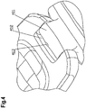
- Fig.4
- is a schematic of the structure of the location of the rotating shaft of the cell phone in the present invention when the flip cover is opened.
- In light of the drawings, the following is a more detailed description of embodiments of the present invention.
- The cell phone device with a hidden suspended microphone in the present invention has a major improvement in the structure of the placement of the microphone in the cell phone. Other parts of the cell phone are known in the existing technology and will not be described here.
- In the cell phone device with a hidden suspended microphone in the present invention, there is a microphone device in a position corresponding to the microphone pickup, comprising a microphone component and a microphone jacket. The aforementioned microphone jacket can be made of hard plastic materials such as PP, ABS and PC, etc., through a molding tool, and preferably can also be made of elastic rubbers such as PVC and silicone, etc., through a molding tool.
- As shown in
Fig.2 , theaforementioned microphone component 201 is slid into theaforementioned microphone jacket 204. They are both suspended and installed on theinner wall 202 of the main body of the cell phone. As shown inFig.3 , the aforementionedmicrophone pickup hole 301 that corresponds to them is located on theouter side 302 of the main body and can be designed into various shapes such as round, oval, a long circle, square and a star shape. As shown inFig.4 , the aforementioned microphone pickup hole can be shielded by the cellphone rotating component 401. - The aforementioned cell
phone rotating component 401 refers to a rotating shaft of the cell phone flip cover or rotating shaft parts of the cell phone video camera, cell phone flashlight or other functional components of a cell phone. - Take a flip over cell phone as an example, as shown in
Fig.4 . Due to the need for rotation movements, acertain activity clearance 402 must be reserved for the aforementioned flip cover between its rotating shaft and the main body of the cell phone. The size and range of such aclearance 402 is generally between 0.3 and 1.0 mm. If it is too large, the overall aesthetic look of the cell phone will be affected; if it is too small, then the flip cover will not rotate flexibly. During a phone conversation, sound may reach the aforementioned microphone component via the aforementioned clearance and the microphone pickup hole. - As shown in
Fig.4 , aprotruding platform 403 can also be designed for the flip shaft part corresponding to the aforementioned microphone pickup hole or an eccentric design can also be used for the flip shaft part, so as to facilitate further sealing of the aforementioned microphone pickup hole, in order to prevent clogging of the aforementioned microphone pickup hole due to entry of debris and dust when affected by static and when the aforementioned flip over cell phone is placed in a pocket or exposed outdoors for a long time, thus affecting speech quality. - Inside the main body of the cell phone corresponding to the aforementioned microphone pickup hole, the aforementioned microphone jacket can also fasten the aforementioned microphone component to the inner wall of the main body of the cell phone by coupling through the following methods:
- As shown in
Fig.2 , theaforementioned microphone jacket 204 is made of a silicone gel material and is shaped through hot molding. Theaforementioned microphone component 201 can be put into the stepped through hole in the center of theaforementioned microphone jacket 204. The side of the aforementioned microphone component with welding spots is flush against the inner side of stepped through hole in the center of the aforementioned microphone jacket. Aninner lead 205 may traverse the aforementioned stepped through hole. On each of the two sides of stepped through hole in the center of the aforementioned microphone jacket, there is a square throughhole 206, whose size and location match two protrudingfasteners 203 made on and corresponding to the inner wall of the aforementioned cell phone main body. The aforementioned microphone jacket is installed inside the aforementioned cell phone main body. The aforementioned protruding fastener pushes the aforementioned microphone jacket tightly against theinner wall 202 of the aforementioned cell phone main body. The stepped surfaces of the aforementioned twofasteners 203 dependably fasten the aforementioned microphone jacket. They are located on the side of the microphone jacket of the microphone pickup hole, and can be lower than the outer surface of the aforementioned cell phone main body or partially level with the outer surface of the aforementioned cell phone main body. But if they are higher than the outer surface of the aforementioned cell phone main body, it may affect the rotating movement of the aforementioned flip cover. - There is a round through hole on each of the two sides of the stepped through hole in the center of the aforementioned microphone jacket. Its size and location match two round columns or round platforms made on and corresponding to the inner wall of the aforementioned cell phone main body. The height of the aforementioned round columns or round platforms is higher than the end surfaces of the aforementioned round through holes by 0.2 to 2 mm. The aforementioned microphone jacket can be installed inside the aforementioned cell phone main body and the aforementioned round columns or round platforms can be ironed and melted with a tool such as an electric iron, etc. The aforementioned microphone jacket can be installed dependably inside the aforementioned cell phone main body. Preferably, the microphone jacket is made of an ABS or PC material and is injection molded.
- There is a round through hole on each of the two sides of the stepped through hole in the center of the aforementioned microphone jacket. Its size and location match two protruding screw pins made on and corresponding to the inner wall of the aforementioned cell phone main body. The height of the aforementioned screw pins is lower than the aforementioned end surfaces of the aforementioned round through holes by 0.2 to 0.5 mm. The aforementioned microphone jacket can be installed inside the aforementioned cell phone main body and a screw driver can be used to screw a screw with a washer into the aforementioned screw pin. The aforementioned microphone jacket can be fastened dependably inside the inner wall of the aforementioned cell phone. Preferably, the microphone jacket is made of an ABS or PC material and is injection molded.
- The aforementioned microphone jacket is made of a plastic material such as ABS or PC, etc. and is injection molded. An ultrasonic melting line is designed on its side that is flush against the aforementioned cell phone main body. The aforementioned microphone jacket can be installed inside the aforementioned cell phone main body and an ultrasonic apparatus and special positioning clamp can be used to dependably fasten the microphone jacket to the inside wall of the aforementioned cell phone main body.
- The cell phone device with a hidden suspended microphone described in the embodiments of the present invention installs its microphone component by using a suspension method. Its structure is simple and compact, thus taking up little space inside the cell phone. The rotating shaft of the cell phone is also used to shield the microphone, thus perfectly guaranteeing the overall effect and aesthetic look of the external design of the cell phone. At the same time, this prevents the user from unwittingly blocking the microphone pickup hole, thus causing the sound heard by the other party to become lower. More rarely, such a structural design far away from the cell phone antenna enables the designer to develop a cell phone product with more stable transmission and reception signals, a thinner main body and a lower radiation to the human brain.
- It should be understood that an ordinary technician in this field can make improvements or changes based on the above description, such as the location of the rotating shaft used to shield the microphone pickup hole on the left side or right side of the cell phone main body and designing the microphone pickup hole and microphone component on the rotating shaft of the cell phone. All such improvements and changes fall into the scope of protection of the claims of the present invention.
Claims (6)
- A cell phone device with a hidden suspended microphone component (201), comprising:- a cell phone main body;- a rotating component (401) is arranged on the cell phone main body, wherein the rotating component (401) is configured as a flip shaft and the cell phone device is a flip over cell phone;- a microphone pickup hole (301) is arranged on the cell phone main body;- within the cell phone main body, there is a microphone component (201) in a position corresponding to the microphone pickup hole (301) used to pick up external sounds;- the microphone pickup hole (301) is arranged on the cell phone main body's inner wall (202) at a place where the cell phone main body is engaged with the rotating component (401), and said microphone pickup hole (301) is shielded by said rotating component (401),characterized in that- an activity clearance (402) is located between the flip shaft (401) and the cell phone main body of between 0.3 and 1.0 mm and- the flip shaft (401) comprises a protruding platform (403) covering the microphone pickup hole (301).
- The cell phone device according to claim 1,- wherein the microphone component (201) is placed on a microphone jacket (204);- said microphone jacket (204) fastening the microphone component (201) to the inner wall (202) of the cell phone main body.
- The cell phone device according to claim 2, wherein the microphone jacket(204) is secured to the inner wall (202) of the cell phone main body with a fastener (203).
- The cell phone device according to claim 2, wherein the microphone jacket is secured to the inner wall of the cell phone main body by way of hot melt glue.
- The cell phone device according to claim 3, wherein the microphone jacket is secured to the inner wall of the cell phone main body by way of a screw.
- The cell phone device according to any of the preceding claims, wherein the rotating component (401) is configured as rotating shaft parts of a cell phone video camera, cell phone flash light or other functional component of the cell phone device.
Applications Claiming Priority (2)
| Application Number | Priority Date | Filing Date | Title |
|---|---|---|---|
| CN2008100664685A CN101257689B (en) | 2008-04-10 | 2008-04-10 | Microphone concealed suspended type mobile phone apparatus |
| PCT/CN2009/071199 WO2009124502A1 (en) | 2008-04-10 | 2009-04-09 | Mobile phone apparatus with hiddenly suspended microphone |
Publications (3)
| Publication Number | Publication Date |
|---|---|
| EP2273845A1 EP2273845A1 (en) | 2011-01-12 |
| EP2273845A4 EP2273845A4 (en) | 2012-09-12 |
| EP2273845B1 true EP2273845B1 (en) | 2018-07-11 |
Family
ID=39892092
Family Applications (1)
| Application Number | Title | Priority Date | Filing Date |
|---|---|---|---|
| EP09730342.4A Not-in-force EP2273845B1 (en) | 2008-04-10 | 2009-04-09 | Mobile phone apparatus with hiddenly suspended microphone |
Country Status (5)
| Country | Link |
|---|---|
| US (1) | US8649831B2 (en) |
| EP (1) | EP2273845B1 (en) |
| CN (1) | CN101257689B (en) |
| ES (1) | ES2688201T3 (en) |
| WO (1) | WO2009124502A1 (en) |
Families Citing this family (1)
| Publication number | Priority date | Publication date | Assignee | Title |
|---|---|---|---|---|
| CN101257689B (en) * | 2008-04-10 | 2011-03-30 | Tcl天一移动通信(深圳)有限公司 | Microphone concealed suspended type mobile phone apparatus |
Citations (2)
| Publication number | Priority date | Publication date | Assignee | Title |
|---|---|---|---|---|
| EP1580966A2 (en) * | 2004-03-26 | 2005-09-28 | Sharp Kabushiki Kaisha | Portable device |
| US20060293091A1 (en) * | 2005-06-28 | 2006-12-28 | Research In Motion Limited | Microphone coupler for a communication device |
Family Cites Families (8)
| Publication number | Priority date | Publication date | Assignee | Title |
|---|---|---|---|---|
| US5692046A (en) * | 1995-11-07 | 1997-11-25 | Motorola, Inc. | Foldable telephone handset having transformable hinge |
| US20020006809A1 (en) * | 2000-07-14 | 2002-01-17 | Tetsuya Kubo | Portable radio terminal device |
| EP1420567A3 (en) * | 2002-11-12 | 2005-03-09 | Samsung Electronics Co., Ltd. | Portable terminal capable of providing stereo sound |
| JP2004214946A (en) * | 2002-12-27 | 2004-07-29 | Casio Comput Co Ltd | Folding type portable information device |
| JP4314095B2 (en) * | 2003-10-30 | 2009-08-12 | 埼玉日本電気株式会社 | Mobile phone |
| JP4443192B2 (en) * | 2003-11-06 | 2010-03-31 | 京セラ株式会社 | Foldable mobile terminal |
| US7415290B2 (en) * | 2004-12-14 | 2008-08-19 | Sony Ericsson Mobile Communications Ab | Mobile terminal with loudspeaker sound redirection |
| CN101257689B (en) * | 2008-04-10 | 2011-03-30 | Tcl天一移动通信(深圳)有限公司 | Microphone concealed suspended type mobile phone apparatus |
-
2008
- 2008-04-10 CN CN2008100664685A patent/CN101257689B/en active Active
-
2009
- 2009-04-09 ES ES09730342.4T patent/ES2688201T3/en active Active
- 2009-04-09 EP EP09730342.4A patent/EP2273845B1/en not_active Not-in-force
- 2009-04-09 US US12/808,123 patent/US8649831B2/en active Active
- 2009-04-09 WO PCT/CN2009/071199 patent/WO2009124502A1/en active Application Filing
Patent Citations (2)
| Publication number | Priority date | Publication date | Assignee | Title |
|---|---|---|---|---|
| EP1580966A2 (en) * | 2004-03-26 | 2005-09-28 | Sharp Kabushiki Kaisha | Portable device |
| US20060293091A1 (en) * | 2005-06-28 | 2006-12-28 | Research In Motion Limited | Microphone coupler for a communication device |
Also Published As
| Publication number | Publication date |
|---|---|
| CN101257689B (en) | 2011-03-30 |
| EP2273845A1 (en) | 2011-01-12 |
| ES2688201T3 (en) | 2018-10-31 |
| EP2273845A4 (en) | 2012-09-12 |
| CN101257689A (en) | 2008-09-03 |
| US20100273541A1 (en) | 2010-10-28 |
| US8649831B2 (en) | 2014-02-11 |
| WO2009124502A1 (en) | 2009-10-15 |
Similar Documents
| Publication | Publication Date | Title |
|---|---|---|
| CN105511561B (en) | Display module | |
| CN1901559B (en) | Communication equipment | |
| KR20130104138A (en) | Waterproof case for portable terminal | |
| CN201349232Y (en) | Handset with a loudspeaker on an upturned cover and a loudspeaker sound cavity sealing structure | |
| AU2011203352B1 (en) | Silicon case | |
| KR100910197B1 (en) | Terminal and mobile terminal apparatus | |
| JPH1127357A (en) | Portable terminal having flip cover | |
| EP1352437B1 (en) | A device with a loudspeaker and an ear piece cover | |
| EP2273845B1 (en) | Mobile phone apparatus with hiddenly suspended microphone | |
| KR20140002785U (en) | Mobile phone protective cover reinforcement in the structure | |
| US7684560B2 (en) | Earset | |
| KR100838248B1 (en) | Extended antenna support for a wireless communications device | |
| US7454014B2 (en) | Device with a loudspeaker and an ear piece cover | |
| KR100310854B1 (en) | Fixing Structure For LCD Module In Wireless Telecommunication Terminal | |
| CN202679437U (en) | Box-type protective sleeve for touch-screen phone | |
| US20100323768A1 (en) | Microphone structure for cell phone | |
| CN213092091U (en) | Waterproof wrist camera of detachable | |
| KR200174762Y1 (en) | Camera lens mounting device of mobile phone | |
| KR20080002166U (en) | Case for mobile terminal | |
| KR20040042477A (en) | Cellular Phone With Stereo Sound Function | |
| CN220673803U (en) | Terminal equipment protective housing | |
| CN212969721U (en) | Local waterproof telephone card storehouse and install its cell-phone | |
| KR20130002185U (en) | A mobile phone case | |
| KR100821140B1 (en) | Multistage Mobile Communication Device | |
| KR200366236Y1 (en) | Portable radiotelephone with touch screen |
Legal Events
| Date | Code | Title | Description |
|---|---|---|---|
| PUAI | Public reference made under article 153(3) epc to a published international application that has entered the european phase |
Free format text: ORIGINAL CODE: 0009012 |
|
| 17P | Request for examination filed |
Effective date: 20101110 |
|
| AK | Designated contracting states |
Kind code of ref document: A1 Designated state(s): AT BE BG CH CY CZ DE DK EE ES FI FR GB GR HR HU IE IS IT LI LT LU LV MC MK MT NL NO PL PT RO SE SI SK TR |
|
| AX | Request for extension of the european patent |
Extension state: AL BA RS |
|
| DAX | Request for extension of the european patent (deleted) | ||
| REG | Reference to a national code |
Ref country code: HK Ref legal event code: DE Ref document number: 1155597 Country of ref document: HK |
|
| A4 | Supplementary search report drawn up and despatched |
Effective date: 20120813 |
|
| RIC1 | Information provided on ipc code assigned before grant |
Ipc: H04M 1/02 20060101ALI20120807BHEP Ipc: H04W 88/02 20090101AFI20120807BHEP Ipc: H04M 1/03 20060101ALI20120807BHEP |
|
| STAA | Information on the status of an ep patent application or granted ep patent |
Free format text: STATUS: EXAMINATION IS IN PROGRESS |
|
| 17Q | First examination report despatched |
Effective date: 20170831 |
|
| GRAP | Despatch of communication of intention to grant a patent |
Free format text: ORIGINAL CODE: EPIDOSNIGR1 |
|
| STAA | Information on the status of an ep patent application or granted ep patent |
Free format text: STATUS: GRANT OF PATENT IS INTENDED |
|
| INTG | Intention to grant announced |
Effective date: 20180201 |
|
| RAP1 | Party data changed (applicant data changed or rights of an application transferred) |
Owner name: TCL COMMUNICATION TECHNOLOGY HOLDINGS LTD. |
|
| GRAS | Grant fee paid |
Free format text: ORIGINAL CODE: EPIDOSNIGR3 |
|
| GRAA | (expected) grant |
Free format text: ORIGINAL CODE: 0009210 |
|
| STAA | Information on the status of an ep patent application or granted ep patent |
Free format text: STATUS: THE PATENT HAS BEEN GRANTED |
|
| AK | Designated contracting states |
Kind code of ref document: B1 Designated state(s): AT BE BG CH CY CZ DE DK EE ES FI FR GB GR HR HU IE IS IT LI LT LU LV MC MK MT NL NO PL PT RO SE SI SK TR |
|
| REG | Reference to a national code |
Ref country code: GB Ref legal event code: FG4D |
|
| REG | Reference to a national code |
Ref country code: CH Ref legal event code: EP |
|
| REG | Reference to a national code |
Ref country code: AT Ref legal event code: REF Ref document number: 1018303 Country of ref document: AT Kind code of ref document: T Effective date: 20180715 |
|
| REG | Reference to a national code |
Ref country code: IE Ref legal event code: FG4D |
|
| REG | Reference to a national code |
Ref country code: DE Ref legal event code: R096 Ref document number: 602009053183 Country of ref document: DE |
|
| REG | Reference to a national code |
Ref country code: ES Ref legal event code: FG2A Ref document number: 2688201 Country of ref document: ES Kind code of ref document: T3 Effective date: 20181031 |
|
| REG | Reference to a national code |
Ref country code: HK Ref legal event code: WD Ref document number: 1155597 Country of ref document: HK |
|
| REG | Reference to a national code |
Ref country code: NL Ref legal event code: MP Effective date: 20180711 |
|
| REG | Reference to a national code |
Ref country code: LT Ref legal event code: MG4D |
|
| REG | Reference to a national code |
Ref country code: AT Ref legal event code: MK05 Ref document number: 1018303 Country of ref document: AT Kind code of ref document: T Effective date: 20180711 |
|
| PG25 | Lapsed in a contracting state [announced via postgrant information from national office to epo] |
Ref country code: NL Free format text: LAPSE BECAUSE OF FAILURE TO SUBMIT A TRANSLATION OF THE DESCRIPTION OR TO PAY THE FEE WITHIN THE PRESCRIBED TIME-LIMIT Effective date: 20180711 |
|
| PG25 | Lapsed in a contracting state [announced via postgrant information from national office to epo] |
Ref country code: FI Free format text: LAPSE BECAUSE OF FAILURE TO SUBMIT A TRANSLATION OF THE DESCRIPTION OR TO PAY THE FEE WITHIN THE PRESCRIBED TIME-LIMIT Effective date: 20180711 Ref country code: IS Free format text: LAPSE BECAUSE OF FAILURE TO SUBMIT A TRANSLATION OF THE DESCRIPTION OR TO PAY THE FEE WITHIN THE PRESCRIBED TIME-LIMIT Effective date: 20181111 Ref country code: GR Free format text: LAPSE BECAUSE OF FAILURE TO SUBMIT A TRANSLATION OF THE DESCRIPTION OR TO PAY THE FEE WITHIN THE PRESCRIBED TIME-LIMIT Effective date: 20181012 Ref country code: BG Free format text: LAPSE BECAUSE OF FAILURE TO SUBMIT A TRANSLATION OF THE DESCRIPTION OR TO PAY THE FEE WITHIN THE PRESCRIBED TIME-LIMIT Effective date: 20181011 Ref country code: NO Free format text: LAPSE BECAUSE OF FAILURE TO SUBMIT A TRANSLATION OF THE DESCRIPTION OR TO PAY THE FEE WITHIN THE PRESCRIBED TIME-LIMIT Effective date: 20181011 Ref country code: AT Free format text: LAPSE BECAUSE OF FAILURE TO SUBMIT A TRANSLATION OF THE DESCRIPTION OR TO PAY THE FEE WITHIN THE PRESCRIBED TIME-LIMIT Effective date: 20180711 Ref country code: SE Free format text: LAPSE BECAUSE OF FAILURE TO SUBMIT A TRANSLATION OF THE DESCRIPTION OR TO PAY THE FEE WITHIN THE PRESCRIBED TIME-LIMIT Effective date: 20180711 Ref country code: LT Free format text: LAPSE BECAUSE OF FAILURE TO SUBMIT A TRANSLATION OF THE DESCRIPTION OR TO PAY THE FEE WITHIN THE PRESCRIBED TIME-LIMIT Effective date: 20180711 Ref country code: PL Free format text: LAPSE BECAUSE OF FAILURE TO SUBMIT A TRANSLATION OF THE DESCRIPTION OR TO PAY THE FEE WITHIN THE PRESCRIBED TIME-LIMIT Effective date: 20180711 |
|
| PG25 | Lapsed in a contracting state [announced via postgrant information from national office to epo] |
Ref country code: HR Free format text: LAPSE BECAUSE OF FAILURE TO SUBMIT A TRANSLATION OF THE DESCRIPTION OR TO PAY THE FEE WITHIN THE PRESCRIBED TIME-LIMIT Effective date: 20180711 Ref country code: LV Free format text: LAPSE BECAUSE OF FAILURE TO SUBMIT A TRANSLATION OF THE DESCRIPTION OR TO PAY THE FEE WITHIN THE PRESCRIBED TIME-LIMIT Effective date: 20180711 |
|
| REG | Reference to a national code |
Ref country code: DE Ref legal event code: R097 Ref document number: 602009053183 Country of ref document: DE |
|
| PG25 | Lapsed in a contracting state [announced via postgrant information from national office to epo] |
Ref country code: CZ Free format text: LAPSE BECAUSE OF FAILURE TO SUBMIT A TRANSLATION OF THE DESCRIPTION OR TO PAY THE FEE WITHIN THE PRESCRIBED TIME-LIMIT Effective date: 20180711 Ref country code: RO Free format text: LAPSE BECAUSE OF FAILURE TO SUBMIT A TRANSLATION OF THE DESCRIPTION OR TO PAY THE FEE WITHIN THE PRESCRIBED TIME-LIMIT Effective date: 20180711 Ref country code: EE Free format text: LAPSE BECAUSE OF FAILURE TO SUBMIT A TRANSLATION OF THE DESCRIPTION OR TO PAY THE FEE WITHIN THE PRESCRIBED TIME-LIMIT Effective date: 20180711 |
|
| PLBE | No opposition filed within time limit |
Free format text: ORIGINAL CODE: 0009261 |
|
| STAA | Information on the status of an ep patent application or granted ep patent |
Free format text: STATUS: NO OPPOSITION FILED WITHIN TIME LIMIT |
|
| PG25 | Lapsed in a contracting state [announced via postgrant information from national office to epo] |
Ref country code: DK Free format text: LAPSE BECAUSE OF FAILURE TO SUBMIT A TRANSLATION OF THE DESCRIPTION OR TO PAY THE FEE WITHIN THE PRESCRIBED TIME-LIMIT Effective date: 20180711 Ref country code: SK Free format text: LAPSE BECAUSE OF FAILURE TO SUBMIT A TRANSLATION OF THE DESCRIPTION OR TO PAY THE FEE WITHIN THE PRESCRIBED TIME-LIMIT Effective date: 20180711 |
|
| 26N | No opposition filed |
Effective date: 20190412 |
|
| PG25 | Lapsed in a contracting state [announced via postgrant information from national office to epo] |
Ref country code: SI Free format text: LAPSE BECAUSE OF FAILURE TO SUBMIT A TRANSLATION OF THE DESCRIPTION OR TO PAY THE FEE WITHIN THE PRESCRIBED TIME-LIMIT Effective date: 20180711 |
|
| REG | Reference to a national code |
Ref country code: CH Ref legal event code: PL |
|
| REG | Reference to a national code |
Ref country code: BE Ref legal event code: MM Effective date: 20190430 |
|
| PG25 | Lapsed in a contracting state [announced via postgrant information from national office to epo] |
Ref country code: LU Free format text: LAPSE BECAUSE OF NON-PAYMENT OF DUE FEES Effective date: 20190409 Ref country code: MC Free format text: LAPSE BECAUSE OF FAILURE TO SUBMIT A TRANSLATION OF THE DESCRIPTION OR TO PAY THE FEE WITHIN THE PRESCRIBED TIME-LIMIT Effective date: 20180711 |
|
| PG25 | Lapsed in a contracting state [announced via postgrant information from national office to epo] |
Ref country code: CH Free format text: LAPSE BECAUSE OF NON-PAYMENT OF DUE FEES Effective date: 20190430 Ref country code: LI Free format text: LAPSE BECAUSE OF NON-PAYMENT OF DUE FEES Effective date: 20190430 |
|
| PG25 | Lapsed in a contracting state [announced via postgrant information from national office to epo] |
Ref country code: BE Free format text: LAPSE BECAUSE OF NON-PAYMENT OF DUE FEES Effective date: 20190430 |
|
| PG25 | Lapsed in a contracting state [announced via postgrant information from national office to epo] |
Ref country code: TR Free format text: LAPSE BECAUSE OF FAILURE TO SUBMIT A TRANSLATION OF THE DESCRIPTION OR TO PAY THE FEE WITHIN THE PRESCRIBED TIME-LIMIT Effective date: 20180711 |
|
| PG25 | Lapsed in a contracting state [announced via postgrant information from national office to epo] |
Ref country code: IE Free format text: LAPSE BECAUSE OF NON-PAYMENT OF DUE FEES Effective date: 20190409 |
|
| PG25 | Lapsed in a contracting state [announced via postgrant information from national office to epo] |
Ref country code: PT Free format text: LAPSE BECAUSE OF FAILURE TO SUBMIT A TRANSLATION OF THE DESCRIPTION OR TO PAY THE FEE WITHIN THE PRESCRIBED TIME-LIMIT Effective date: 20181111 |
|
| PG25 | Lapsed in a contracting state [announced via postgrant information from national office to epo] |
Ref country code: CY Free format text: LAPSE BECAUSE OF FAILURE TO SUBMIT A TRANSLATION OF THE DESCRIPTION OR TO PAY THE FEE WITHIN THE PRESCRIBED TIME-LIMIT Effective date: 20180711 |
|
| PG25 | Lapsed in a contracting state [announced via postgrant information from national office to epo] |
Ref country code: HU Free format text: LAPSE BECAUSE OF FAILURE TO SUBMIT A TRANSLATION OF THE DESCRIPTION OR TO PAY THE FEE WITHIN THE PRESCRIBED TIME-LIMIT; INVALID AB INITIO Effective date: 20090409 Ref country code: MT Free format text: LAPSE BECAUSE OF FAILURE TO SUBMIT A TRANSLATION OF THE DESCRIPTION OR TO PAY THE FEE WITHIN THE PRESCRIBED TIME-LIMIT Effective date: 20180711 |
|
| PGFP | Annual fee paid to national office [announced via postgrant information from national office to epo] |
Ref country code: ES Payment date: 20210621 Year of fee payment: 13 |
|
| PG25 | Lapsed in a contracting state [announced via postgrant information from national office to epo] |
Ref country code: MK Free format text: LAPSE BECAUSE OF FAILURE TO SUBMIT A TRANSLATION OF THE DESCRIPTION OR TO PAY THE FEE WITHIN THE PRESCRIBED TIME-LIMIT Effective date: 20180711 |
|
| PGFP | Annual fee paid to national office [announced via postgrant information from national office to epo] |
Ref country code: IT Payment date: 20220420 Year of fee payment: 14 Ref country code: GB Payment date: 20220425 Year of fee payment: 14 Ref country code: FR Payment date: 20220421 Year of fee payment: 14 Ref country code: DE Payment date: 20220420 Year of fee payment: 14 |
|
| REG | Reference to a national code |
Ref country code: ES Ref legal event code: FD2A Effective date: 20230526 |
|
| PG25 | Lapsed in a contracting state [announced via postgrant information from national office to epo] |
Ref country code: ES Free format text: LAPSE BECAUSE OF NON-PAYMENT OF DUE FEES Effective date: 20220410 |
|
| REG | Reference to a national code |
Ref country code: DE Ref legal event code: R119 Ref document number: 602009053183 Country of ref document: DE |
|
| GBPC | Gb: european patent ceased through non-payment of renewal fee |
Effective date: 20230409 |
|
| PG25 | Lapsed in a contracting state [announced via postgrant information from national office to epo] |
Ref country code: GB Free format text: LAPSE BECAUSE OF NON-PAYMENT OF DUE FEES Effective date: 20230409 |
|
| PG25 | Lapsed in a contracting state [announced via postgrant information from national office to epo] |
Ref country code: GB Free format text: LAPSE BECAUSE OF NON-PAYMENT OF DUE FEES Effective date: 20230409 Ref country code: FR Free format text: LAPSE BECAUSE OF NON-PAYMENT OF DUE FEES Effective date: 20230430 Ref country code: DE Free format text: LAPSE BECAUSE OF NON-PAYMENT OF DUE FEES Effective date: 20231103 |
|
| PG25 | Lapsed in a contracting state [announced via postgrant information from national office to epo] |
Ref country code: IT Free format text: LAPSE BECAUSE OF NON-PAYMENT OF DUE FEES Effective date: 20230409 |