EP2273767A1 - Sliding rail structure of sliding closure mobile phone and its implementing method - Google Patents
Sliding rail structure of sliding closure mobile phone and its implementing method Download PDFInfo
- Publication number
- EP2273767A1 EP2273767A1 EP09733243A EP09733243A EP2273767A1 EP 2273767 A1 EP2273767 A1 EP 2273767A1 EP 09733243 A EP09733243 A EP 09733243A EP 09733243 A EP09733243 A EP 09733243A EP 2273767 A1 EP2273767 A1 EP 2273767A1
- Authority
- EP
- European Patent Office
- Prior art keywords
- sliding rail
- cell phone
- holes
- sliding
- aforementioned
- Prior art date
- Legal status (The legal status is an assumption and is not a legal conclusion. Google has not performed a legal analysis and makes no representation as to the accuracy of the status listed.)
- Granted
Links
- 238000000034 method Methods 0.000 title claims description 20
- 238000005553 drilling Methods 0.000 claims 3
- 238000010079 rubber tapping Methods 0.000 claims 2
- 230000008878 coupling Effects 0.000 abstract 1
- 238000010168 coupling process Methods 0.000 abstract 1
- 238000005859 coupling reaction Methods 0.000 abstract 1
- 238000010586 diagram Methods 0.000 description 8
- 239000000463 material Substances 0.000 description 4
- 238000005336 cracking Methods 0.000 description 3
- 239000007769 metal material Substances 0.000 description 3
- XEEYBQQBJWHFJM-UHFFFAOYSA-N Iron Chemical compound [Fe] XEEYBQQBJWHFJM-UHFFFAOYSA-N 0.000 description 2
- 239000002184 metal Substances 0.000 description 2
- 229910052751 metal Inorganic materials 0.000 description 2
- 229910052742 iron Inorganic materials 0.000 description 1
Images


Classifications
-
- H—ELECTRICITY
- H04—ELECTRIC COMMUNICATION TECHNIQUE
- H04M—TELEPHONIC COMMUNICATION
- H04M1/00—Substation equipment, e.g. for use by subscribers
- H04M1/02—Constructional features of telephone sets
- H04M1/0202—Portable telephone sets, e.g. cordless phones, mobile phones or bar type handsets
- H04M1/0206—Portable telephones comprising a plurality of mechanically joined movable body parts, e.g. hinged housings
- H04M1/0208—Portable telephones comprising a plurality of mechanically joined movable body parts, e.g. hinged housings characterized by the relative motions of the body parts
- H04M1/0235—Slidable or telescopic telephones, i.e. with a relative translation movement of the body parts; Telephones using a combination of translation and other relative motions of the body parts
- H04M1/0237—Sliding mechanism with one degree of freedom
Definitions
- the present invention relates to a slide cell phone device and methods.
- it relates to the improvement of a sliding rail structure that connects the main body and the slide and its method.
- Slide cell phones generally place cell phone displays, etc., on the slide.
- the keys of the cell phone are placed on the main body and the main body and the slide are connected by the sliding rails on the two sides.
- its sliding rails are made of metal parts plus plastic strips and include a sliding rail fastener 110 and a sliding rail moving part 120. Between the sliding rail fastener 110 and the sliding rail moving part 120, there is a sliding rail slider 130.
- a plurality of threaded holes 140 are correspondingly placed and used to be respectively fastened and connected to the slide and the cell phone main body.
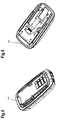
- Fig.1 In the sliding rail structure in the existing technology, the principles of sliding are shown in Fig.1 .
- the sliding rail fastener 110 is fastened to the main body.
- the sliding rail moving part 120 is fastened to the bottom enclosure of the slide.
- the cell phone's slide is driven by the sliding rail moving part to slide it up and down.
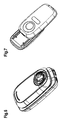
- Fig.2 an ordinary sliding rail structure in the existing technology is shown in Fig.2 , wherein the screw hole has not been processed at all. Only a screw thread is tapped on an iron sheet with a thickness of 0.5 mm. It has a short effective distance. During long time use, it is extremely easy for the screw to become detached due to frequent sliding and vibrations.
- the slider which is placed between the sliding rail fastener and the sliding rail moving part, is generally made of a plastic material and is mainly used to muffle noise and facilitate sliding.
- the impact ductility of the plastic material is limited. If it falls, the two ends of the sliding rail slider 130 will be subject to a great impact, and the two ends are highly likely to break, thus causing structural damage.
- the purpose of the present invention is to provide a sliding rail structure of a sliding cell phone and a method for use, whereby through improving the structure of the sliding rail slider placed between sliding rail fastener and the sliding rail moving part, the stress capability of the sliding rail is improved, thus effectively controlling the possibility of an unsmooth sliding of the cell phone slide.
- a sliding rail structure of a sliding cell phone comprising a sliding rail fastener fastened to the cell phone main body, a sliding rail slider and a sliding rail moving part that fastens and connects to the cell phone slide.
- the aforementioned sliding rail slider is placed between the aforementioned sliding rail fastener and the aforementioned sliding rail moving part and is used to muffle noise and facilitate sliding; it is characterized in that a plurality of protruding platforms are placed at the location that fastens the aforementioned sliding rail slider and the aforementioned sliding rail fastener, for use in fitting and holding the aforementioned sliding rail fastener on top.
- the aforementioned sliding rail structure wherein on the aforementioned sliding rail fastener, a plurality of first threaded holes are placed at locations for use in connecting to the aforementioned cell phone main body.
- the aforementioned first threaded holes are placed within a protrusion.
- the aforementioned sliding rail structure wherein on the aforementioned sliding rail moving part, a plurality of second threaded holes are placed at locations for connection to the aforementioned cell phone slide.
- the aforementioned second threaded holes are placed within a protrusion.
- a method for making the sliding rail of a slide cell phone which comprises the following steps:
- a sliding rail structure of a sliding cell phone and its method are provided by the present invention, wherein, in the sliding rail structure, a plurality of protruding platforms are placed on the sliding rail slider to improve the stress capability of the sliding rail, thus effectively controlling the possibility of cracking on the plastic heads on the two ends of the slider and thus causing unsmooth sliding. Therefore, the product yield and lifecycle are improved.
- the sliding rail structure of a slide cell phone in the present invention comprises a sliding rail fastener 210 fastened to the cell phone main body 100, a sliding rail slider 230 and a sliding rail moving part 220 that fastens and connects to the cell phone slide 300.
- the aforementioned sliding rail slider 230 is placed between the aforementioned sliding rail fastener 210 and the aforementioned sliding rail moving part 220, and is used to muffle noise and facilitate sliding.
- the aforementioned sliding rail fastener 210 in the present invention is placed in a way that through the aforementioned sliding rail slider 230, it is fastened to the aforementioned sliding rail moving part 220.
- the sliding rail moving part 220 can slide relative to the aforementioned sliding rail fastener 210. Therefore, the sliding rail fastener 210 and the aforementioned sliding rail moving part 220 in the present invention can be used alternatively and just need to be changed in shape according to the specific requirements of the cell phone structure.
- the aforementioned sliding rail fastener 210 and the aforementioned sliding rail slider 230 are fastened and, near the two ends of the sliding rail fastener 210, two holes 212 with an identical U shape are placed.
- the sliding rail slider 230 is partially exposed; the material of the periphery of the aforementioned holes is folded, and peripheries of the body holes of the original sliding rail fastener 210 overlap.
- first threaded holes 211 are also placed. Also, the first threaded holes 211 are placed in a way so that their peripheries protrude. The holes are also drilled in a way so that the metal on the peripheries of the holes protrudes slightly. Thus, after they protrude, inside the first threaded holes 211 (at this time, there is no screw thread yet; so more accurately, these are the first holes parts), the thickness of the holes increases and then screw threads are tapped on their interior walls. The effective length of their screw threads can be thicker than the single sheet of the existing technology, thus making it possible to easily and securely fit the appropriate screw and quite securely fasten the aforementioned cell phone main body and the aforementioned sliding rail fastener 210.
- a plurality of second threaded holes 221 are also placed at locations that connect to the cell phone slide 300.
- the second threaded holes 221 are also placed in a way so that they protrude. That is, they protrude at the locations of the parts for the second holes (at this time, there is no screw thread yet).
- the holes are drilled and the metallic material on the peripheries of the hole parts protrude slightly. Then the thickness of the parts of the second holes also increases. Screw threads are tapped on the interior walls.
- the effective length of the second threaded holes 221 is increased, thus efficiently controlling the issue of the detachment of screws and achieving the function of positioning and securing the slide, and preventing the issue of the loosening and detachment of the sliding rail 200 and the cell phone slide.
- its sliding rail structure uses an embodiment described above, comprising a sliding rail fastener fastened to the cell phone main body, a sliding rail slider and a sliding rail moving part that fastens and connects to the cell phone slide.
- the aforementioned sliding rail slider is placed between the aforementioned sliding rail fastener and the aforementioned sliding rail moving part and is used to muffle noise and facilitate sliding.
- the one protruding platform on the sliding rail slider 230 changes into three protruding platforms 130, greatly improving the stress capabilities of the sliding rail 200, making it unlikely for the plastic head on the two ends of the sliding rail slider 230 to crack, so that the sliding rail moving part 220 slides up and down more smoothly along the direction of the sliding rail slider 230.
- its sliding rail structure uses an embodiment described above, comprising a sliding rail fastener fastened to the cell phone main body, a sliding rail slider and a sliding rail moving part that fastens and connects to the cell phone slide.
- the aforementioned sliding rail slider is placed between the aforementioned sliding rail fastener and the aforementioned sliding rail moving part and is used to muffle noise and facilitate sliding.
- the method comprises the following steps:
- the protruding placement of the aforementioned first threaded holes and second threaded holes increases the effective length of the threaded holes, efficiently controlling the issue of a detachment of screws and achieving the function of positioning and securing the cell phone main body and slide. That is, it efficiently prevents the issue of the easy loosening and detachment of the sliding rail 200, the cell phone slide 300 and the cell phone main body 100, making the connection and fastening among them more secure.
- the assembly steps of the slide cell phone in the present invention comprise:
- a sliding rail structure of a sliding cell phone and its method of use is provided by the present invention. Since three protruding platforms are placed on the slider between the sliding fastener and the sliding moving part instead of the one protruding platform originally, for fitting and holding the sliding rail fastener on its top, this improves the stress capabilities of the slider, thus efficiently controlling the possibility of cracking on the plastic heads on the two ends of the slider and thus causing unsmooth sliding.
- the flanged placement of the threaded holes at locations that connect the sliding rail fastener to the cell phone main body and locations that connect the sliding rail moving part and the cell phone slide increases the effective length of the original screw threads, thus properly preventing the detachment of screws, which cause the detachment of the sliding rail from the cell phone main body and the detachment of the sliding rail from the cell phone slide.
Landscapes
- Engineering & Computer Science (AREA)
- Signal Processing (AREA)
- Telephone Set Structure (AREA)
- Bearings For Parts Moving Linearly (AREA)
Abstract
Description
- The present invention relates to a slide cell phone device and methods. In particular, it relates to the improvement of a sliding rail structure that connects the main body and the slide and its method.
- In the existing technology, the use of cell phone devices has become more and more extensive and there are more and more styles of cell phones. Currently, major cell phone styles include the straight style, the upper flip style, the lower flip style and the slide style. With the slide cell phones, in addition to shrinking the volume, they can also make the exterior of the cell phone more fashionable while increasing the fun of using it.
- Slide cell phones generally place cell phone displays, etc., on the slide. The keys of the cell phone are placed on the main body and the main body and the slide are connected by the sliding rails on the two sides. As shown in
Fig.1 and Fig.2 , to ensure the lifecycle and reliability of an ordinary cell phone, its sliding rails are made of metal parts plus plastic strips and include a slidingrail fastener 110 and a slidingrail moving part 120. Between the slidingrail fastener 110 and the slidingrail moving part 120, there is asliding rail slider 130. On the aforementioned slidingrail fastener 110 and the aforementioned slidingrail moving part 120, a plurality of threadedholes 140 are correspondingly placed and used to be respectively fastened and connected to the slide and the cell phone main body. - In the sliding rail structure in the existing technology, the principles of sliding are shown in
Fig.1 . Generally, the slidingrail fastener 110 is fastened to the main body. The slidingrail moving part 120 is fastened to the bottom enclosure of the slide. Thus, the cell phone's slide is driven by the sliding rail moving part to slide it up and down. Generally, an ordinary sliding rail structure in the existing technology is shown inFig.2 , wherein the screw hole has not been processed at all. Only a screw thread is tapped on an iron sheet with a thickness of 0.5 mm. It has a short effective distance. During long time use, it is extremely easy for the screw to become detached due to frequent sliding and vibrations. - Also, the slider, which is placed between the sliding rail fastener and the sliding rail moving part, is generally made of a plastic material and is mainly used to muffle noise and facilitate sliding. The impact ductility of the plastic material is limited. If it falls, the two ends of the
sliding rail slider 130 will be subject to a great impact, and the two ends are highly likely to break, thus causing structural damage. - One must be very careful when using a slide cell phone with such a structure and handle it gently. In particular, one must take care not to drop it from any height. Otherwise, it is quite easy to cause the cell phone to break and not to slide smoothly, thus causing great inconvenience to the user.
- Therefore, the above sliding rail structure needs to be improved.
- The purpose of the present invention is to provide a sliding rail structure of a sliding cell phone and a method for use, whereby through improving the structure of the sliding rail slider placed between sliding rail fastener and the sliding rail moving part, the stress capability of the sliding rail is improved, thus effectively controlling the possibility of an unsmooth sliding of the cell phone slide.
- The technical solution of the present invention is as follows:
- A sliding rail structure of a sliding cell phone, comprising a sliding rail fastener fastened to the cell phone main body, a sliding rail slider and a sliding rail moving part that fastens and connects to the cell phone slide. The aforementioned sliding rail slider is placed between the aforementioned sliding rail fastener and the aforementioned sliding rail moving part and is used to muffle noise and facilitate sliding; it is characterized in that a plurality of protruding platforms are placed at the location that fastens the aforementioned sliding rail slider and the aforementioned sliding rail fastener, for use in fitting and holding the aforementioned sliding rail fastener on top.
- The aforementioned sliding rail structure, wherein three of the aforementioned protruding platforms are placed.
- The aforementioned sliding rail structure, wherein on the aforementioned sliding rail fastener, a plurality of first threaded holes are placed at locations for use in connecting to the aforementioned cell phone main body. The aforementioned first threaded holes are placed within a protrusion.
- The aforementioned sliding rail structure, wherein on the aforementioned sliding rail moving part, a plurality of second threaded holes are placed at locations for connection to the aforementioned cell phone slide. The aforementioned second threaded holes are placed within a protrusion.
- A method for making the sliding rail of a slide cell phone, which comprises the following steps:
- A. In the aforementioned sliding rail fastener, at a location that fastens to the aforementioned sliding rail slider, two holes are drilled, so as to partially expose the sliding rail slider;
- B. The periphery of the aforementioned holes is flanged so that three protruding platforms are formed on the sliding rail slider.
- The aforementioned method, which also comprises the following steps:
- C. In the aforementioned sliding rail fastener, at locations that connect to the aforementioned cell phone main body, a plurality of first holes are drilled, so as to cause their peripheries to protrude; and
- D. A thread is tapped inside the aforementioned first holes to form the first threaded holes.
- The aforementioned method, which also comprises the following steps:
- E. In the aforementioned sliding rail moving part, at locations that connect to the aforementioned cell phone slide, a plurality of second holes are drilled, so as to cause their peripheries to protrude; and
- F. A thread is tapped inside the aforementioned second holes to form the second threaded holes.
- The aforementioned method, wherein in the aforementioned step A, the aforementioned holes are placed near the two ends of the sliding rail fastener.
- The aforementioned method, wherein in the aforementioned step A, the aforementioned holes are U shaped holes.
- A sliding rail structure of a sliding cell phone and its method are provided by the present invention, wherein, in the sliding rail structure, a plurality of protruding platforms are placed on the sliding rail slider to improve the stress capability of the sliding rail, thus effectively controlling the possibility of cracking on the plastic heads on the two ends of the slider and thus causing unsmooth sliding. Therefore, the product yield and lifecycle are improved.
- Captions for the Diagrams:
- Fig.1
- is a diagram of a sliding rail structure of a sliding cell phone in the existing technology and its principles for sliding;
- Fig.2
- is a diagram of an ordinary sliding rail structure of a sliding cell phone in the existing technology;
- Fig.3
- is a diagram of a sliding rail structure according to the present invention;
- Fig.4
- is a diagram of the connecting and fastening device between a cell phone main body and a sliding rail fastener according to the present invention;
- Fig.5
- is a diagram of the connecting and fastening device between the sliding cell phone slide and the sliding rail moving part pursuant to the present invention;
- Fig.6
- is a diagram of the connecting and fastening device between the sliding cell phone main body and the sliding rail in the present invention; and
- Fig.7
- is a schematic illustration of the state of the slide in the present invention that slides along with the sliding rail moving part.
- The following is a further and more detailed description of the preferred embodiments of the present invention in light of the diagrams.
- The sliding rail structure of a slide cell phone in the present invention, as shown in
Fig.3 , comprises a slidingrail fastener 210 fastened to the cell phonemain body 100, a slidingrail slider 230 and a slidingrail moving part 220 that fastens and connects to thecell phone slide 300. The aforementioned slidingrail slider 230 is placed between the aforementioned slidingrail fastener 210 and the aforementioned slidingrail moving part 220, and is used to muffle noise and facilitate sliding. - As shown in
Fig.3 , the aforementioned slidingrail fastener 210 in the present invention is placed in a way that through the aforementioned slidingrail slider 230, it is fastened to the aforementioned slidingrail moving part 220. The slidingrail moving part 220 can slide relative to the aforementioned slidingrail fastener 210. Therefore, the slidingrail fastener 210 and the aforementioned slidingrail moving part 220 in the present invention can be used alternatively and just need to be changed in shape according to the specific requirements of the cell phone structure. - In the sliding rail structure of the slide cell phone in present invention, the aforementioned sliding
rail fastener 210 and the aforementioned slidingrail slider 230 are fastened and, near the two ends of the slidingrail fastener 210, twoholes 212 with an identical U shape are placed. The slidingrail slider 230 is partially exposed; the material of the periphery of the aforementioned holes is folded, and peripheries of the body holes of the original slidingrail fastener 210 overlap. - Thus, even if the one protruding platform on the sliding
rail slider 230 changes into three protrudingplatforms 130 and the three protruding platforms are used to fit and hold the aforementioned slidingrail fastener 220 on top. - This can improve the stress capabilities of the entire sliding
rail slider 230, thus effectively preventing the possibility of cracking of the plastic heads on the two ends of theslider 230 and the issue of unsmooth sliding. - On the aforementioned sliding
rail fastener 210, at locations that connect to the cell phonemain body 100, a plurality of first threadedholes 211 are also placed. Also, the first threadedholes 211 are placed in a way so that their peripheries protrude. The holes are also drilled in a way so that the metal on the peripheries of the holes protrudes slightly. Thus, after they protrude, inside the first threaded holes 211 (at this time, there is no screw thread yet; so more accurately, these are the first holes parts), the thickness of the holes increases and then screw threads are tapped on their interior walls. The effective length of their screw threads can be thicker than the single sheet of the existing technology, thus making it possible to easily and securely fit the appropriate screw and quite securely fasten the aforementioned cell phone main body and the aforementioned slidingrail fastener 210. - Thus, by increasing the effective length of the first threaded holes, the issue of screw detachment is efficiently controlled and the function of positioning and fastening the screw is achieved. That is the issue of the loosening and detachment of a sliding
rail 200 and cell phonemain body 100 is resolved, thus eliminating the risk of damage through a fall from a certain height. - In the sliding rail structure of the slide cell phone in present invention, as shown in
Fig.3 , on the aforementioned slidingrail moving part 220, a plurality of second threadedholes 221 are also placed at locations that connect to thecell phone slide 300. The second threadedholes 221 are also placed in a way so that they protrude. That is, they protrude at the locations of the parts for the second holes (at this time, there is no screw thread yet). The holes are drilled and the metallic material on the peripheries of the hole parts protrude slightly. Then the thickness of the parts of the second holes also increases. Screw threads are tapped on the interior walls. Thus, the effective length of the second threadedholes 221 is increased, thus efficiently controlling the issue of the detachment of screws and achieving the function of positioning and securing the slide, and preventing the issue of the loosening and detachment of the slidingrail 200 and the cell phone slide. - In the method to achieve the sliding rail structure of the slide cell phone in the present invention, its sliding rail structure uses an embodiment described above, comprising a sliding rail fastener fastened to the cell phone main body, a sliding rail slider and a sliding rail moving part that fastens and connects to the cell phone slide. The aforementioned sliding rail slider is placed between the aforementioned sliding rail fastener and the aforementioned sliding rail moving part and is used to muffle noise and facilitate sliding. The method to achieve these results comprises the following steps:
- A. In the aforementioned sliding
rail fastener 210, at a location that fastens to the aforementioned slidingrail slider 210 near the two ends of the slidingrail fastener 210, twoU-shaped holes 212 are drilled so as to partially expose the slidingrail slider 230; - B. The material of the periphery of the aforementioned holes is folded, and peripheries of the body holes of the original sliding
rail fastener 210 overlap; - Thus, the one protruding platform on the sliding
rail slider 230 changes into three protrudingplatforms 130, greatly improving the stress capabilities of the slidingrail 200, making it unlikely for the plastic head on the two ends of the slidingrail slider 230 to crack, so that the slidingrail moving part 220 slides up and down more smoothly along the direction of the slidingrail slider 230. - In the method to achieve the sliding rail structure of the slide cell phone in present invention, its sliding rail structure uses an embodiment described above, comprising a sliding rail fastener fastened to the cell phone main body, a sliding rail slider and a sliding rail moving part that fastens and connects to the cell phone slide. The aforementioned sliding rail slider is placed between the aforementioned sliding rail fastener and the aforementioned sliding rail moving part and is used to muffle noise and facilitate sliding. The method comprises the following steps:
- A. In the aforementioned sliding
rail fastener 210, at locations that connect to the aforementioned cell phonemain body 100, drill a plurality of first holes, so that the metallic materials on the peripheries of the holes protrude slightly, thus increasing the effective length of the interior walls of the first holes; - B. Screw threads are tapped inside the aforementioned first holes and form the first threaded
holes 211; - C. In the aforementioned sliding
rail moving part 220, at locations that connect to the aforementionedcell phone slide 300, drill a plurality of second holes, so that the metallic materials on the peripheries of the holes protrude slightly, thus increasing the effective length of the interior walls of the first holes; and - D. Tap screw threads inside the aforementioned second holes and form the second threaded
holes 221. - The protruding placement of the aforementioned first threaded holes and second threaded holes increases the effective length of the threaded holes, efficiently controlling the issue of a detachment of screws and achieving the function of positioning and securing the cell phone main body and slide. That is, it efficiently prevents the issue of the easy loosening and detachment of the sliding
rail 200, thecell phone slide 300 and the cell phonemain body 100, making the connection and fastening among them more secure. - The assembly steps of the slide cell phone in the present invention comprise:
- fastening the sliding
rail fastener 210 to the cell phonemain body 100 by a screw as shown inFig.4 ; - fastening the sliding
rail moving part 220 to theslide 300 by a screw as shown inFig.5 ; - fastening and connecting the cell phone main body100 and the
cell phone slide 300 by the slidingrail 200 and assembling a complete slide cell phone as shown inFig.6 ; thecell phone slide 300 slides up and down along the direction of the slidingrail slider 230 with the slidingrail 200, as shown inFig.7 . - A sliding rail structure of a sliding cell phone and its method of use is provided by the present invention. Since three protruding platforms are placed on the slider between the sliding fastener and the sliding moving part instead of the one protruding platform originally, for fitting and holding the sliding rail fastener on its top, this improves the stress capabilities of the slider, thus efficiently controlling the possibility of cracking on the plastic heads on the two ends of the slider and thus causing unsmooth sliding.
- The flanged placement of the threaded holes at locations that connect the sliding rail fastener to the cell phone main body and locations that connect the sliding rail moving part and the cell phone slide increases the effective length of the original screw threads, thus properly preventing the detachment of screws, which cause the detachment of the sliding rail from the cell phone main body and the detachment of the sliding rail from the cell phone slide.
- It should be understood that the above description of an embodiment is rather detailed and cannot be understood to be any limitation to the scope of patent protection for the present invention. The scope of patent protection for the present invention should be subject to the claims attached.
Claims (9)
- A sliding rail structure of a slide cell phone, comprising:- a sliding rail fastener fastened to the cell phone main body;- a sliding rail slider;- a sliding rail moving part that fastens and connects to a cell phone slide, wherein the sliding rail slider being placed between the sliding rail fastener and the sliding rail moving part and being used to muffle noise and to facilitate sliding; and- a plurality of protruding platforms placed at locations that fasten the sliding rail slider and the sliding rail fastener, for fitting and holding the sliding rail fastener.
- The sliding rail structure according to claim 1, wherein the number of the protruding platforms placed is three.
- The sliding rail structure according to claim 2, wherein, on the sliding rail fastener, a plurality of first threaded holes are placed at locations for use in connecting to the cell phone main body, and wherein the first threaded holes are placed with protruding peripheries.
- The sliding rail structure according to claim 3, wherein, on the aforementioned sliding rail moving part, a plurality of second threaded holes are placed at locations for use in connecting to the cell phone slide, and wherein the second threaded holes are placed with protruding peripheries.
- A method to achieve a sliding rail structure of a slide cell phone, comprising:- drilling two holes on a sliding rail fastener at a location that fastens to a sliding rail slider, so as to partially expose the sliding rail slider; and- flanging the periphery of the holes, so that three protruding platforms are formed on the sliding rail slider.
- The method according to claim 5, further comprising:- drilling a plurality of first holes on the sliding rail fastener, at locations that connect to the cell phone main body, so as to cause their peripheries to protrude; and- tapping a thread inside the first holes to form the first threaded holes.
- The method according to claim 5, further comprising:- drilling a plurality of second holes on the sliding rail moving part, at locations that connect to the cell phone slide, so as to cause their peripheries to protrude; and- tapping a thread inside the second holes to form the second threaded holes.
- The method according to claim 5, wherein the holes are placed near the two ends of the sliding rail fastener.
- The method according to claim 5, wherein the holes are U-shaped holes.
Applications Claiming Priority (2)
| Application Number | Priority Date | Filing Date | Title |
|---|---|---|---|
| CN2008100666426A CN101267466B (en) | 2008-04-15 | 2008-04-15 | A sliding rail structure for sliding cover mobile phone and its realization method |
| PCT/CN2009/071252 WO2009127146A1 (en) | 2008-04-15 | 2009-04-13 | Sliding rail structure of sliding closure mobile phone and its implementing method |
Publications (3)
| Publication Number | Publication Date |
|---|---|
| EP2273767A1 true EP2273767A1 (en) | 2011-01-12 |
| EP2273767A4 EP2273767A4 (en) | 2012-03-21 |
| EP2273767B1 EP2273767B1 (en) | 2015-04-01 |
Family
ID=39989596
Family Applications (1)
| Application Number | Title | Priority Date | Filing Date |
|---|---|---|---|
| EP09733243.1A Not-in-force EP2273767B1 (en) | 2008-04-15 | 2009-04-13 | Sliding rail structure of sliding closure mobile phone and its implementing method |
Country Status (5)
| Country | Link |
|---|---|
| US (1) | US8218758B2 (en) |
| EP (1) | EP2273767B1 (en) |
| CN (1) | CN101267466B (en) |
| ES (1) | ES2540936T3 (en) |
| WO (1) | WO2009127146A1 (en) |
Families Citing this family (7)
| Publication number | Priority date | Publication date | Assignee | Title |
|---|---|---|---|---|
| CN101267466B (en) * | 2008-04-15 | 2011-07-27 | 捷开通讯(深圳)有限公司 | A sliding rail structure for sliding cover mobile phone and its realization method |
| CN103475756A (en) | 2008-11-24 | 2013-12-25 | 柳相圭 | Portable terminal |
| CN102379073B (en) * | 2009-02-25 | 2015-01-21 | 联想创新有限公司(香港) | Cable containing structure for slide housing, slide unit, electronic apparatus, and cable containing method |
| US20130104027A1 (en) * | 2011-10-21 | 2013-04-25 | Daniel Bennett | Systems, methods, and interfaces for display of inline content and block level content on an access device |
| TWI495801B (en) * | 2012-10-09 | 2015-08-11 | Wistron Corp | Sliding mechanism and slider electronic apparatus therewith |
| ES2874531T3 (en) | 2015-05-29 | 2021-11-05 | Medaxis Ag | Nozzle element for projecting a jet of water |
| CN111447306B (en) * | 2019-01-17 | 2021-06-08 | 北京小米移动软件有限公司 | Shell assembly and terminal equipment |
Citations (4)
| Publication number | Priority date | Publication date | Assignee | Title |
|---|---|---|---|---|
| WO2005091515A1 (en) * | 2004-02-10 | 2005-09-29 | Hansang Lee | Sliding mechanism apparatus and appliance integrated with the same |
| WO2006006776A1 (en) * | 2004-07-08 | 2006-01-19 | Hitech Parts Co., Ltd. | Slider assembly for sliding-type mobile phone and cellular phone having the slider assembly |
| EP1742449A2 (en) * | 2005-07-09 | 2007-01-10 | LG Electronics Inc. | Slide module and mobile terminal having the same |
| CN101052057A (en) * | 2007-05-09 | 2007-10-10 | 苏州恒翔通信科技有限公司 | Two-way slide cover cell phone |
Family Cites Families (6)
| Publication number | Priority date | Publication date | Assignee | Title |
|---|---|---|---|---|
| US20050054397A1 (en) * | 2003-09-08 | 2005-03-10 | Samsung Electronics Co., Ltd. | Portable sliding-type digital communication device and locking apparatus thereof |
| WO2006095382A1 (en) * | 2005-02-18 | 2006-09-14 | Fujitsu Limited | Sliding portable telephone |
| CN2862520Y (en) * | 2005-12-02 | 2007-01-24 | 英业达股份有限公司 | Cover-sliding intelligent type mobile phone structure |
| US7583989B2 (en) * | 2006-04-18 | 2009-09-01 | Cheng Uei Precision Industry Co., Ltd. | Sliding-type hinge |
| CN200976612Y (en) * | 2006-12-08 | 2007-11-14 | 华为技术有限公司 | Sliding structure of sliding closure terminal equipment |
| CN101267466B (en) * | 2008-04-15 | 2011-07-27 | 捷开通讯(深圳)有限公司 | A sliding rail structure for sliding cover mobile phone and its realization method |
-
2008
- 2008-04-15 CN CN2008100666426A patent/CN101267466B/en not_active Expired - Fee Related
-
2009
- 2009-04-13 EP EP09733243.1A patent/EP2273767B1/en not_active Not-in-force
- 2009-04-13 ES ES09733243.1T patent/ES2540936T3/en active Active
- 2009-04-13 WO PCT/CN2009/071252 patent/WO2009127146A1/en active Application Filing
- 2009-04-13 US US12/920,250 patent/US8218758B2/en active Active
Patent Citations (4)
| Publication number | Priority date | Publication date | Assignee | Title |
|---|---|---|---|---|
| WO2005091515A1 (en) * | 2004-02-10 | 2005-09-29 | Hansang Lee | Sliding mechanism apparatus and appliance integrated with the same |
| WO2006006776A1 (en) * | 2004-07-08 | 2006-01-19 | Hitech Parts Co., Ltd. | Slider assembly for sliding-type mobile phone and cellular phone having the slider assembly |
| EP1742449A2 (en) * | 2005-07-09 | 2007-01-10 | LG Electronics Inc. | Slide module and mobile terminal having the same |
| CN101052057A (en) * | 2007-05-09 | 2007-10-10 | 苏州恒翔通信科技有限公司 | Two-way slide cover cell phone |
Non-Patent Citations (1)
| Title |
|---|
| See also references of WO2009127146A1 * |
Also Published As
| Publication number | Publication date |
|---|---|
| CN101267466B (en) | 2011-07-27 |
| EP2273767A4 (en) | 2012-03-21 |
| US20110002562A1 (en) | 2011-01-06 |
| EP2273767B1 (en) | 2015-04-01 |
| ES2540936T3 (en) | 2015-07-14 |
| CN101267466A (en) | 2008-09-17 |
| US8218758B2 (en) | 2012-07-10 |
| WO2009127146A1 (en) | 2009-10-22 |
Similar Documents
| Publication | Publication Date | Title |
|---|---|---|
| US8218758B2 (en) | Sliding rail structure of a sliding cell phone and its methods | |
| JP4969391B2 (en) | Portable device to which a strap can be attached | |
| CN107741759A (en) | Mobile terminal, housing unit, display module and its assembly method | |
| CN105388969A (en) | Back protective cover for tablet device | |
| CN201594966U (en) | Chip card retaining structure and portable electronic apparatus using the same | |
| US8411424B2 (en) | Strap mounting structure and electronic device using the same | |
| US9249604B2 (en) | Locking and insertion structure | |
| CN106909069A (en) | A kind of intelligent watch of battery-disassembled | |
| CN105472081B (en) | A kind of mobile phone side key assembling structure and the mobile phone side key for the assembling structure | |
| CN205596211U (en) | Cell -phone snap ware | |
| CN203313225U (en) | Slide mobile phone | |
| CN202048744U (en) | Refrigerator connecting structure and refrigerator | |
| CN210694026U (en) | Uncapping shell and electronic terminal | |
| CN204102971U (en) | Portable electric appts | |
| CN204156908U (en) | A kind of gripping device with cramped construction | |
| CN209710219U (en) | A kind of mounting structure | |
| CN204046979U (en) | The shell mechanism of LED drive power | |
| CN205750323U (en) | A kind of fixed structure of watch displays screen | |
| CN103137364B (en) | Key structure | |
| CN206909903U (en) | A kind of novel intelligent solar energy bracelet | |
| CN216774244U (en) | Basalt composite material cable hook | |
| CN102801834B (en) | Slide phone casing | |
| CN102469717B (en) | Clamping module and portable electronic device using same | |
| CN206004727U (en) | Electronic equipment | |
| CN102568542B (en) | Electronic device and method for attaching actuation button |
Legal Events
| Date | Code | Title | Description |
|---|---|---|---|
| PUAI | Public reference made under article 153(3) epc to a published international application that has entered the european phase |
Free format text: ORIGINAL CODE: 0009012 |
|
| 17P | Request for examination filed |
Effective date: 20101110 |
|
| AK | Designated contracting states |
Kind code of ref document: A1 Designated state(s): AT BE BG CH CY CZ DE DK EE ES FI FR GB GR HR HU IE IS IT LI LT LU LV MC MK MT NL NO PL PT RO SE SI SK TR |
|
| AX | Request for extension of the european patent |
Extension state: AL BA RS |
|
| DAX | Request for extension of the european patent (deleted) | ||
| A4 | Supplementary search report drawn up and despatched |
Effective date: 20120216 |
|
| RIC1 | Information provided on ipc code assigned before grant |
Ipc: H04M 1/02 20060101AFI20120210BHEP Ipc: H05K 7/18 20060101ALI20120210BHEP |
|
| REG | Reference to a national code |
Ref country code: HK Ref legal event code: DE Ref document number: 1155593 Country of ref document: HK |
|
| 17Q | First examination report despatched |
Effective date: 20131122 |
|
| GRAP | Despatch of communication of intention to grant a patent |
Free format text: ORIGINAL CODE: EPIDOSNIGR1 |
|
| INTG | Intention to grant announced |
Effective date: 20141023 |
|
| GRAS | Grant fee paid |
Free format text: ORIGINAL CODE: EPIDOSNIGR3 |
|
| GRAA | (expected) grant |
Free format text: ORIGINAL CODE: 0009210 |
|
| AK | Designated contracting states |
Kind code of ref document: B1 Designated state(s): AT BE BG CH CY CZ DE DK EE ES FI FR GB GR HR HU IE IS IT LI LT LU LV MC MK MT NL NO PL PT RO SE SI SK TR |
|
| REG | Reference to a national code |
Ref country code: GB Ref legal event code: FG4D |
|
| REG | Reference to a national code |
Ref country code: CH Ref legal event code: EP |
|
| REG | Reference to a national code |
Ref country code: IE Ref legal event code: FG4D |
|
| REG | Reference to a national code |
Ref country code: DE Ref legal event code: R096 Ref document number: 602009030339 Country of ref document: DE Effective date: 20150513 |
|
| REG | Reference to a national code |
Ref country code: AT Ref legal event code: REF Ref document number: 719684 Country of ref document: AT Kind code of ref document: T Effective date: 20150515 |
|
| REG | Reference to a national code |
Ref country code: ES Ref legal event code: FG2A Ref document number: 2540936 Country of ref document: ES Kind code of ref document: T3 Effective date: 20150714 |
|
| REG | Reference to a national code |
Ref country code: NL Ref legal event code: VDEP Effective date: 20150401 |
|
| REG | Reference to a national code |
Ref country code: AT Ref legal event code: MK05 Ref document number: 719684 Country of ref document: AT Kind code of ref document: T Effective date: 20150401 |
|
| REG | Reference to a national code |
Ref country code: LT Ref legal event code: MG4D |
|
| PG25 | Lapsed in a contracting state [announced via postgrant information from national office to epo] |
Ref country code: NL Free format text: LAPSE BECAUSE OF FAILURE TO SUBMIT A TRANSLATION OF THE DESCRIPTION OR TO PAY THE FEE WITHIN THE PRESCRIBED TIME-LIMIT Effective date: 20150401 |
|
| PG25 | Lapsed in a contracting state [announced via postgrant information from national office to epo] |
Ref country code: FI Free format text: LAPSE BECAUSE OF FAILURE TO SUBMIT A TRANSLATION OF THE DESCRIPTION OR TO PAY THE FEE WITHIN THE PRESCRIBED TIME-LIMIT Effective date: 20150401 Ref country code: CZ Free format text: LAPSE BECAUSE OF FAILURE TO SUBMIT A TRANSLATION OF THE DESCRIPTION OR TO PAY THE FEE WITHIN THE PRESCRIBED TIME-LIMIT Effective date: 20150401 Ref country code: NO Free format text: LAPSE BECAUSE OF FAILURE TO SUBMIT A TRANSLATION OF THE DESCRIPTION OR TO PAY THE FEE WITHIN THE PRESCRIBED TIME-LIMIT Effective date: 20150701 Ref country code: PT Free format text: LAPSE BECAUSE OF FAILURE TO SUBMIT A TRANSLATION OF THE DESCRIPTION OR TO PAY THE FEE WITHIN THE PRESCRIBED TIME-LIMIT Effective date: 20150803 Ref country code: HR Free format text: LAPSE BECAUSE OF FAILURE TO SUBMIT A TRANSLATION OF THE DESCRIPTION OR TO PAY THE FEE WITHIN THE PRESCRIBED TIME-LIMIT Effective date: 20150401 Ref country code: LT Free format text: LAPSE BECAUSE OF FAILURE TO SUBMIT A TRANSLATION OF THE DESCRIPTION OR TO PAY THE FEE WITHIN THE PRESCRIBED TIME-LIMIT Effective date: 20150401 |
|
| PG25 | Lapsed in a contracting state [announced via postgrant information from national office to epo] |
Ref country code: IS Free format text: LAPSE BECAUSE OF FAILURE TO SUBMIT A TRANSLATION OF THE DESCRIPTION OR TO PAY THE FEE WITHIN THE PRESCRIBED TIME-LIMIT Effective date: 20150801 Ref country code: AT Free format text: LAPSE BECAUSE OF FAILURE TO SUBMIT A TRANSLATION OF THE DESCRIPTION OR TO PAY THE FEE WITHIN THE PRESCRIBED TIME-LIMIT Effective date: 20150401 Ref country code: GR Free format text: LAPSE BECAUSE OF FAILURE TO SUBMIT A TRANSLATION OF THE DESCRIPTION OR TO PAY THE FEE WITHIN THE PRESCRIBED TIME-LIMIT Effective date: 20150702 Ref country code: LV Free format text: LAPSE BECAUSE OF FAILURE TO SUBMIT A TRANSLATION OF THE DESCRIPTION OR TO PAY THE FEE WITHIN THE PRESCRIBED TIME-LIMIT Effective date: 20150401 |
|
| REG | Reference to a national code |
Ref country code: CH Ref legal event code: PL |
|
| REG | Reference to a national code |
Ref country code: DE Ref legal event code: R097 Ref document number: 602009030339 Country of ref document: DE |
|
| REG | Reference to a national code |
Ref country code: IE Ref legal event code: MM4A |
|
| PG25 | Lapsed in a contracting state [announced via postgrant information from national office to epo] |
Ref country code: CH Free format text: LAPSE BECAUSE OF NON-PAYMENT OF DUE FEES Effective date: 20150430 Ref country code: EE Free format text: LAPSE BECAUSE OF FAILURE TO SUBMIT A TRANSLATION OF THE DESCRIPTION OR TO PAY THE FEE WITHIN THE PRESCRIBED TIME-LIMIT Effective date: 20150401 Ref country code: MC Free format text: LAPSE BECAUSE OF FAILURE TO SUBMIT A TRANSLATION OF THE DESCRIPTION OR TO PAY THE FEE WITHIN THE PRESCRIBED TIME-LIMIT Effective date: 20150401 Ref country code: DK Free format text: LAPSE BECAUSE OF FAILURE TO SUBMIT A TRANSLATION OF THE DESCRIPTION OR TO PAY THE FEE WITHIN THE PRESCRIBED TIME-LIMIT Effective date: 20150401 Ref country code: LI Free format text: LAPSE BECAUSE OF NON-PAYMENT OF DUE FEES Effective date: 20150430 |
|
| PLBE | No opposition filed within time limit |
Free format text: ORIGINAL CODE: 0009261 |
|
| STAA | Information on the status of an ep patent application or granted ep patent |
Free format text: STATUS: NO OPPOSITION FILED WITHIN TIME LIMIT |
|
| PG25 | Lapsed in a contracting state [announced via postgrant information from national office to epo] |
Ref country code: PL Free format text: LAPSE BECAUSE OF FAILURE TO SUBMIT A TRANSLATION OF THE DESCRIPTION OR TO PAY THE FEE WITHIN THE PRESCRIBED TIME-LIMIT Effective date: 20150401 Ref country code: RO Free format text: LAPSE BECAUSE OF NON-PAYMENT OF DUE FEES Effective date: 20150401 Ref country code: SK Free format text: LAPSE BECAUSE OF FAILURE TO SUBMIT A TRANSLATION OF THE DESCRIPTION OR TO PAY THE FEE WITHIN THE PRESCRIBED TIME-LIMIT Effective date: 20150401 |
|
| 26N | No opposition filed |
Effective date: 20160105 |
|
| REG | Reference to a national code |
Ref country code: FR Ref legal event code: PLFP Year of fee payment: 8 |
|
| PG25 | Lapsed in a contracting state [announced via postgrant information from national office to epo] |
Ref country code: IE Free format text: LAPSE BECAUSE OF NON-PAYMENT OF DUE FEES Effective date: 20150413 |
|
| PG25 | Lapsed in a contracting state [announced via postgrant information from national office to epo] |
Ref country code: SI Free format text: LAPSE BECAUSE OF FAILURE TO SUBMIT A TRANSLATION OF THE DESCRIPTION OR TO PAY THE FEE WITHIN THE PRESCRIBED TIME-LIMIT Effective date: 20150401 |
|
| PG25 | Lapsed in a contracting state [announced via postgrant information from national office to epo] |
Ref country code: BE Free format text: LAPSE BECAUSE OF FAILURE TO SUBMIT A TRANSLATION OF THE DESCRIPTION OR TO PAY THE FEE WITHIN THE PRESCRIBED TIME-LIMIT Effective date: 20150401 |
|
| PG25 | Lapsed in a contracting state [announced via postgrant information from national office to epo] |
Ref country code: MT Free format text: LAPSE BECAUSE OF FAILURE TO SUBMIT A TRANSLATION OF THE DESCRIPTION OR TO PAY THE FEE WITHIN THE PRESCRIBED TIME-LIMIT Effective date: 20150401 |
|
| REG | Reference to a national code |
Ref country code: FR Ref legal event code: PLFP Year of fee payment: 9 |
|
| PG25 | Lapsed in a contracting state [announced via postgrant information from national office to epo] |
Ref country code: BG Free format text: LAPSE BECAUSE OF FAILURE TO SUBMIT A TRANSLATION OF THE DESCRIPTION OR TO PAY THE FEE WITHIN THE PRESCRIBED TIME-LIMIT Effective date: 20150401 Ref country code: HU Free format text: LAPSE BECAUSE OF FAILURE TO SUBMIT A TRANSLATION OF THE DESCRIPTION OR TO PAY THE FEE WITHIN THE PRESCRIBED TIME-LIMIT; INVALID AB INITIO Effective date: 20090413 |
|
| PG25 | Lapsed in a contracting state [announced via postgrant information from national office to epo] |
Ref country code: CY Free format text: LAPSE BECAUSE OF FAILURE TO SUBMIT A TRANSLATION OF THE DESCRIPTION OR TO PAY THE FEE WITHIN THE PRESCRIBED TIME-LIMIT Effective date: 20150401 Ref country code: SE Free format text: LAPSE BECAUSE OF FAILURE TO SUBMIT A TRANSLATION OF THE DESCRIPTION OR TO PAY THE FEE WITHIN THE PRESCRIBED TIME-LIMIT Effective date: 20150401 |
|
| PG25 | Lapsed in a contracting state [announced via postgrant information from national office to epo] |
Ref country code: TR Free format text: LAPSE BECAUSE OF FAILURE TO SUBMIT A TRANSLATION OF THE DESCRIPTION OR TO PAY THE FEE WITHIN THE PRESCRIBED TIME-LIMIT Effective date: 20150401 |
|
| PG25 | Lapsed in a contracting state [announced via postgrant information from national office to epo] |
Ref country code: LU Free format text: LAPSE BECAUSE OF NON-PAYMENT OF DUE FEES Effective date: 20150413 |
|
| REG | Reference to a national code |
Ref country code: FR Ref legal event code: PLFP Year of fee payment: 10 |
|
| PG25 | Lapsed in a contracting state [announced via postgrant information from national office to epo] |
Ref country code: MK Free format text: LAPSE BECAUSE OF FAILURE TO SUBMIT A TRANSLATION OF THE DESCRIPTION OR TO PAY THE FEE WITHIN THE PRESCRIBED TIME-LIMIT Effective date: 20150401 |
|
| REG | Reference to a national code |
Ref country code: HK Ref legal event code: WD Ref document number: 1155593 Country of ref document: HK |
|
| PGFP | Annual fee paid to national office [announced via postgrant information from national office to epo] |
Ref country code: ES Payment date: 20210621 Year of fee payment: 13 |
|
| PGFP | Annual fee paid to national office [announced via postgrant information from national office to epo] |
Ref country code: IT Payment date: 20220420 Year of fee payment: 14 Ref country code: GB Payment date: 20220425 Year of fee payment: 14 Ref country code: FR Payment date: 20220421 Year of fee payment: 14 Ref country code: DE Payment date: 20220420 Year of fee payment: 14 |
|
| REG | Reference to a national code |
Ref country code: ES Ref legal event code: FD2A Effective date: 20230529 |
|
| PG25 | Lapsed in a contracting state [announced via postgrant information from national office to epo] |
Ref country code: ES Free format text: LAPSE BECAUSE OF NON-PAYMENT OF DUE FEES Effective date: 20220414 |
|
| REG | Reference to a national code |
Ref country code: DE Ref legal event code: R119 Ref document number: 602009030339 Country of ref document: DE |
|
| GBPC | Gb: european patent ceased through non-payment of renewal fee |
Effective date: 20230413 |
|
| PG25 | Lapsed in a contracting state [announced via postgrant information from national office to epo] |
Ref country code: GB Free format text: LAPSE BECAUSE OF NON-PAYMENT OF DUE FEES Effective date: 20230413 |
|
| PG25 | Lapsed in a contracting state [announced via postgrant information from national office to epo] |
Ref country code: GB Free format text: LAPSE BECAUSE OF NON-PAYMENT OF DUE FEES Effective date: 20230413 Ref country code: FR Free format text: LAPSE BECAUSE OF NON-PAYMENT OF DUE FEES Effective date: 20230430 Ref country code: DE Free format text: LAPSE BECAUSE OF NON-PAYMENT OF DUE FEES Effective date: 20231103 |
|
| PG25 | Lapsed in a contracting state [announced via postgrant information from national office to epo] |
Ref country code: IT Free format text: LAPSE BECAUSE OF NON-PAYMENT OF DUE FEES Effective date: 20230413 |