EP2273642A2 - Procédé et appareil pour la reconfiguration automatique d'un système de distribution d'alimentation électrique avec protection améliorée - Google Patents
Procédé et appareil pour la reconfiguration automatique d'un système de distribution d'alimentation électrique avec protection améliorée Download PDFInfo
- Publication number
- EP2273642A2 EP2273642A2 EP10163827A EP10163827A EP2273642A2 EP 2273642 A2 EP2273642 A2 EP 2273642A2 EP 10163827 A EP10163827 A EP 10163827A EP 10163827 A EP10163827 A EP 10163827A EP 2273642 A2 EP2273642 A2 EP 2273642A2
- Authority
- EP
- European Patent Office
- Prior art keywords
- node
- switch
- nodes
- team
- switches
- Prior art date
- Legal status (The legal status is an assumption and is not a legal conclusion. Google has not performed a legal analysis and makes no representation as to the accuracy of the status listed.)
- Granted
Links
Images


Classifications
-
- H—ELECTRICITY
- H02—GENERATION; CONVERSION OR DISTRIBUTION OF ELECTRIC POWER
- H02J—CIRCUIT ARRANGEMENTS OR SYSTEMS FOR SUPPLYING OR DISTRIBUTING ELECTRIC POWER; SYSTEMS FOR STORING ELECTRIC ENERGY
- H02J13/00—Circuit arrangements for providing remote indication of network conditions, e.g. an instantaneous record of the open or closed condition of each circuitbreaker in the network; Circuit arrangements for providing remote control of switching means in a power distribution network, e.g. switching in and out of current consumers by using a pulse code signal carried by the network
-
- H—ELECTRICITY
- H02—GENERATION; CONVERSION OR DISTRIBUTION OF ELECTRIC POWER
- H02H—EMERGENCY PROTECTIVE CIRCUIT ARRANGEMENTS
- H02H7/00—Emergency protective circuit arrangements specially adapted for specific types of electric machines or apparatus or for sectionalised protection of cable or line systems, and effecting automatic switching in the event of an undesired change from normal working conditions
- H02H7/26—Sectionalised protection of cable or line systems, e.g. for disconnecting a section on which a short-circuit, earth fault, or arc discharge has occured
- H02H7/261—Sectionalised protection of cable or line systems, e.g. for disconnecting a section on which a short-circuit, earth fault, or arc discharge has occured involving signal transmission between at least two stations
-
- H—ELECTRICITY
- H02—GENERATION; CONVERSION OR DISTRIBUTION OF ELECTRIC POWER
- H02H—EMERGENCY PROTECTIVE CIRCUIT ARRANGEMENTS
- H02H3/00—Emergency protective circuit arrangements for automatic disconnection directly responsive to an undesired change from normal electric working condition with or without subsequent reconnection ; integrated protection
- H02H3/006—Calibration or setting of parameters
-
- H—ELECTRICITY
- H02—GENERATION; CONVERSION OR DISTRIBUTION OF ELECTRIC POWER
- H02H—EMERGENCY PROTECTIVE CIRCUIT ARRANGEMENTS
- H02H1/00—Details of emergency protective circuit arrangements
- H02H1/0061—Details of emergency protective circuit arrangements concerning transmission of signals
-
- H—ELECTRICITY
- H02—GENERATION; CONVERSION OR DISTRIBUTION OF ELECTRIC POWER
- H02H—EMERGENCY PROTECTIVE CIRCUIT ARRANGEMENTS
- H02H7/00—Emergency protective circuit arrangements specially adapted for specific types of electric machines or apparatus or for sectionalised protection of cable or line systems, and effecting automatic switching in the event of an undesired change from normal working conditions
- H02H7/26—Sectionalised protection of cable or line systems, e.g. for disconnecting a section on which a short-circuit, earth fault, or arc discharge has occured
- H02H7/30—Staggered disconnection
Definitions
- the present invention generally relates to improvements in control of an electric power distribution system, and more specifically to the use of intelligent autonomous nodes for isolating faulted sections of distribution lines, reconfiguring, and restoring service to end customers (circuit reconfiguration), and improving circuit protection.
- the power distribution systems of this invention are generally of low to medium-voltage distribution feeders (ranging from approximately 4 KV to 69 KV) originating in power distribution substations and leading to the source of supply for end customers of an electrical supply utility or agency.
- low to medium-voltage distribution feeders ranging from approximately 4 KV to 69 KV
- the methodologies for building, operating and maintaining the lower voltage systems are different. These methodologies are dictated by much larger quantities and geographical dispersion of distribution equipment, and by much lower quantities of electrical power supplied per mile of circuit. This creates requirements for lower cost, modular, standardized equipment, which can be installed, operated and maintained with minimal labor and human supervision.
- failures of the distribution feeder occur due to downed power lines, excavation of underground cable or other causes and are typically detectable by sensing excess (short circuit/overcurrent) current, and occasionally by detecting loss of voltage.
- a loss of voltage complaint by the customer is the means by which the utility senses the outage, responding by dispatching a crew to isolate the fault and reconfigure the distribution system.
- the typical devices for isolating these faults are circuit breakers located primarily in distribution substations and fuses located on tap lines or at customer transformers.
- the substation breakers are generally provided with reclosing relays that cause the breaker to close several times after the breaker has detected an overcurrent condition and tripped open.
- sectionalizer refers to a specific family of automatic, fault isolating devices described below, while the terms “sectionalizing” and sectionalize” are used to describe the process of isolating a faulted section of line, which can be performed by all of the classes of switches described above.
- the "line recloser" is typically a pre-packaged, version of the substation breaker with reclosing relay.
- Line reclosers typically consist of a fault-break switching device with integrated current sensing, plus a control enclosure containing fault detection hardware, control logic, user interface module, and battery-backed power supply.
- a line recloser When placed on the distribution line between the substation and customer loads, a line recloser is typically set up with fault detection settings coordinated to operate before the substation breaker trips and to correspondingly prevent the substation breaker from tripping. This has the effect of reducing the number of customers affected by an end of line fault. On very long feeders, the more sensitive settings can be used to protect the feeder from faults of a magnitude too low to be detected reliably by the substation circuit breaker.
- Multiple line reclosers can be placed on a distribution line in series, although it becomes increasingly difficult or impossible to coordinate their settings such that only the nearest recloser on the source side of the fault operates.
- the "interrupter” is typically a pre-packaged breaker and fault relay without automatic reclosing capability. Interrupters are used primarily in underground power distribution systems.
- the "automatic line sectionalizer” or “sectionalizer” is typically a prepackaged combination of a load-break switch used in conjunction with a device known as a "line sectionalizer control".
- the sectionalizer senses current (and optionally voltage) such that the operation of the circuit and the source-side protective device can be monitored.
- the sectionalizer is configured to open its switch under certain circumstances when the circuit is de-energized after some number of pre-configured voltage losses have occurred within a brief time interval. The circumstances vary from product to product, but are always based upon sensing of conditions caused by faults followed shortly by voltage losses. Sectionalizers are designed to coordinate with the operation of the circuit's protective devices.
- Typical sectionalizers are devices such as the Cooper Power Systems Sectionalizer type GV or GW manufactured by Cooper industries, Inc, or the EnergyLine Systems Model 2801-SC Switch Control manufactured by EnergyLine Systems. These are all well-known devices within the industry, and thus need not be described in detail herein.
- Baumann, Velez, and Gelbein disclose methodologies tailored to non-fault break sectionalizing switches with breakers or reclosers only at the sources of supply.
- methodologies for integrating substation breakers, line reclosers, sectionalizers, and other equipment into generalized, automatic circuit reconfiguration systems have been limited. There are numerous reasons for this, related primarily to the nature of electric distribution systems:
- Examples of recent improvements in recloser technology include the Form 4c and Form 5c Recloser Controls manufactured by Cooper Industries, the SEL 351 R Recloser Control manufactured by Schweitzer Engineering Laboratories, Inc. and the N, U, and W Series Recloser Controls manufactured by Nu-Lec Pt. Ltd. These products are capable of internally maintaining at least two separate sets of protective relay settings, selectable by the customer at the front panel or over communications. These sets of settings can be loosely referred-to as "profiles" of protection characteristics, and may include a wide variety of selections including operating modes, protection features enabled, and level settings.
- a primary aspect of the present invention is to provide methodology and related system apparatus for using and coordinating the use of information conveyed over communications to dynamically modify the protection characteristics of distribution devices (including but not limited to substation breakers, reclosing substation breakers, and line reclosers). In this way, overall protection and reconfigurability of the distribution system or "team" is greatly enhanced.
- distribution devices including but not limited to substation breakers, reclosing substation breakers, and line reclosers.
- devices within the system in accordance with the present invention recognize the existence of cooperating devices outside of the team's domain of direct control, managing information from these devices such that more intelligent local decision making and inter-team coordination can be performed.
- This information may include logical status indications, control requests, analog values or other data as will be presented below.
- the present invention comprises novel improvements to a method and system for controlling an electric power distribution system.
- the following description is presented to enable any person skilled in the art to make and use the invention, and is provided in the context of particular applications and their requirements.
- Various modifications to the preferred embodiment will be readily apparent to those skilled in the art, and the generic principles defined herein may be applied to other embodiments and applications without departing from the spirit and scope of the invention.
- the present invention is not intended to be limited to the embodiment shown, but is to be accorded the widest possible scope consistent with the principles and features disclosed herein.
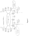
- FIG. 1 shows a simplified view of a portion of an exemplary electrical power distribution system that can be controlled by a preferred embodiment of the present invention.
- the distribution system comprises a plurality of sources of electrical power 102 connected to a plurality of users 104 (e.g., factories, homes, etc.) through an electrical distribution line 106 such as conventional electrical power lines.
- Distribution line 106 has a plurality of nodes 108 placed at predetermined points along the line 106.
- the depiction of the number of sources, users, lines and nodes ) in Figure 1 is arbitrary and there may be a different configuration or number of each of these components in any given distribution system.
- the present invention enables devices within the system team to recognize the existence of auxiliary or "sideline" devices (for example, 130A and 130B) outside of the team's domain of direct control, actively maintaining information from these devices such that more intelligent local decision making and inter-team coordination can be performed.
- devices within the team may be configured to supply information over communications ) channels, (for example, 131A and 131 B) as sideline team members of other teams. This information may include logical status indications, control requests, analog values or other data.
- Figure 2 depicts a presently preferred embodiment of a node 200 in accordance with the invention.
- Distribution line 202 passes through switch 204 which can open and close the distribution line at this point.
- the switch 204 can be replaced by other devices capable of performing power sensing, control or conditioning functions such as voltage regulation (voltage regulators) reactive power control, (switched capacitor banks), fault sensing, etc.
- the node 200 may also be of a type for controlling two (dual), three, or more switches, with customer loads or alternate sources between the switches.
- the distribution line 202 would pass through two or more switches 204 which can open and close independently under the control of the single node 200.
- node 200 is a single node from the standpoint of communications, but is multiple nodes from the standpoint of the power system and the control algorithms of the present invention. In this circumstance, the information flow is unchanged, but the communication step is simply bypassed.
- Node controller 206 controls distribution switch 204.
- Node controller 206 includes a control computer 208, a display 209, and an associated memory 210.
- Memory 210 stores the programming to control the node and stores the database of node records about each node in the system.
- a significant feature of the present invention is the addition of information elements 17-18 in the node records 210 to reflect protective characteristics of the node as explained below.
- a significant feature of the present invention relates to enhancements to team operation when node 200 has protective (overcurrent protection/fault break) capabilities.
- distribution switch 204 can have different operating capabilities which may enhance or detract from its ability to participate in circuit reconfiguration.
- the lowest-cost switches may not be capable of interrupting high currents, or may not be outfitted with both voltage and current sensors.
- node 200 may be programmed not to open the switch under high interrupting currents (sectionalizing switch control), or alternatively may be programmed as a "circuit protective device" (recloser or breaker). When programmed as a protective device, the switch is opened under overcurrent conditions (fault current) to prevent fire or damage to the circuit or to customer equipment, and also for safety concerns.
- distribution devices including but not limited to substation breakers, reclosing substation breakers, and line reclosers.
- the automated control methodology can redefine the role of a line recloser into a line sectionalizer or into an entirely non-automatic switch to reduce problems with coordination between multiple protective devices. Since the algorithms are applied dynamically, there is no need to customize the procedural operation for each circuit configuration. Since each device automatically recognizes its role within the team, coordination of the protective devices is greatly facilitated by the improvements detailed below.
- Control computer 208 is connected to AC waveform processor 212.
- AC waveform processor 212 is connected through field interface connector 214 to distribution line 202. This allows the processor to measure various critical parameters of the electricity on the distribution line such as, voltage and current, digitally convert them, and send them to the control computer for processing, communications, or storage in memory.
- Digital I/O interface 216 is connected to control computer 208, switch 204 and distribution line 202. Digital I/O interface 216 allows computer controller 206 to receive switch position sensing information and other inputs, and to output control outputs to the switch.
- Communications device 218 is connected to control computer 208 and allows it to communicate with other nodes on the system through communications channel 110 of Figure 1 .
- the communications devices can be connected to any communications network that is conveniently available and has the desired characteristics. In a current embodiment of the invention, a Metricom Radio is used.
- a second, optional, communications device 220 can be included in the node, if desired, for use by systems other than the present invention.
- Power is supplied to the node through power supply/battery backup 222.
- the battery can be charged from solar power, an AC potential transformer, or from power supplied through the voltage sensors.
- Each of the nodes is connected to a communications channel 110.
- Any type of communications channel can be used.
- the communications channel could be telephone, radio, the Internet, or fiber optic cable.
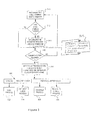
- FIG. 3 is a flow diagram which illustrates the operation of a synchronization counter and state selection process run by each node in accordance with the presently preferred embodiment.
- the nodes update their timer and database sequence counter which are used to synchronize the nodes with each other.
- the nodes then check for error conditions and set error flags if errors are found and determine from their database which state they are in: synchronization, integrity check, or reconfiguration event.
- An enhancement to the synchronization process is the addition of step 315 to provide protective devices with "advance notice" of their protective characteristics prior to a reconfiguration even such that initial restoration of the circuit may begin prior to adjustment of protective device profiles if the prior settings are adequate.
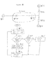
- FIG. 4 is a flow diagram which illustrates the operation of the synchronization process state run by each node in accordance with the presently preferred embodiment.
- the nodes construct a database of critical control information about the distribution system. All nodes contribute to the construction of a database. Each node stores in its memory a copy of the database.
- the steps in constructing the database in accordance with the presently preferred embodiment are as follows: each node receives the database from the previous node, adds its own record of information and passes the database on to the next node. This process continues until all nodes have received a record from every other node. Once this process is compete, each node then proceeds to the integrity check state shown in Figure 5
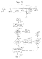
- Figure 5 is a flow diagram which illustrates the operation of the integrity check state process run by each node in accordance with the presently preferred embodiment.
- a node runs this process, it checks the records it has received from all the other nodes to ensure that the records reflect a timely version of the state of the system.
- FIG. 6 is a flow diagram which illustrates the operation of the transfer process state in accordance with the presently preferred embodiment.
- This flow diagram describes the process used by each node upon the occurrence of a fault in the system followed by standalone sectionalization. This process is also started in a node when the node receives a message that another node has entered this process. In order to restore electric power service to as many users as possible after a fault has occurred, each node will use this process to determine if it can close its associated switch(es).
- the present invention extends the functionality of the transfer logic to insure that the protection settings match the requirements of the transfer (steps 645-654).
- Figure 7 describes the logic used by each node to return the distribution system to its normal state once the fault has been cleared.
- the present invention extends the functionality of the return-to-normal logic to insure that the protection settings match the requirements of the return-to-normal transition, particularly when the "closed" transition is used (steps 722 and 750-752).
- Figure 8 is a flow diagram which illustrates the operation of a task timer that is used during the transfer process state of Figure 6 and the return to normal process state of Figure 7 in order ensure that the system does not take too much time to complete the steps required in either of these processes.
- the present invention extends the functionality of the return-to-normal logic to reset the protection settings when the return-to-normal transition, and in particular when the "closed" transition return-to-normal is used (steps 830-831).
- memory 210 stores the programming to control the node and stores a database of node records about each node in the system (team database). Each record includes a number of fields which include information that allows the node controller to control the node's switch(es) to alter the distribution line characteristics in response to distribution system demands.
- a major improvement in the present invention is the addition of protective characteristics to the team database, facilitating coordination of protection settings during load transfer/restoration.
- the ordering of the node records in the database corresponds to the physical ordering of the nodes in the distribution system. It would not deviate from the present invention to have the node records in the database ordered in some other fashion and to include information in each node record of the node's actual or relative physical position in the distribution system. If the node controller is of a dual or multiple switch type, the position of each switch is represented in the database and may be ordered independently.
- a single, dual or multiple switch node from the standpoint of communications can be used as the only member of the team. It will be seen that doing so is completely consistent with the preferred embodiment of the invention.
- a dual switch node may act as the only member of the team when it is the only member physically installed (other members may be installed later), when other members of the team have been temporarily removed from the team, or when errors at other nodes in the team prevent the entire team from acting upon an outage condition.
- a preferred embodiment of the invention is for controlling a loop distribution system as in Figure 1 in which there are two sources and a normally open switch (a "tie" switch) in the distribution line between the two sources, or a radial distribution system in which there is one source and no tie switch. It would not deviate from the present invention for the database to represent simpler or more complex distribution system topologies and for the invention to be able to work on such topologies.
- the tie switch can close to restore load (backfeed) from either side, depending on which side of the switch is energized and which side is deenergized.
- the circuit is described as having a "right” side and a “left” side, with the tie switch between the right and left sides.
- the lowest numbered node is designated as being closest to the source on the left side of the circuit, and the highest numbered node as being closest to the source on the right side.
- the circuit traversed between each of two adjacent nodes is referred to as a "transfer segment" or "segment”.
- each node's database record includes: (1) record currently in use flag, (2) indication of the type of device represented by each individual record, (3) the node's communication address, (4) its normal switch(es) state(s) (open or closed), (5 present switch(es) state(s), (6) the voltage state (is voltage present on the line or not)(by position if applicable), (7) the fault state (has a fault been detected)(by position if applicable), (8) the present time stamp (9) the database sequence number, (10) the logic process state (what state and step is the switch in), (11) error condition status flags, (12) automatic/manual operation mode status (by position if applicable), (13) average of the sensed loads on each phase (by position if applicable), (14) time stamp at start of event process, (15) indication of method of return to normal (open or closed transition), (16) indication of whether the node was within the affected portion of the circuit, (17) maximum number of segments that can be adequately protected with the current protective settings when feeding the circuit from the left side,
- a segment represents the distribution line between two adjacent team nodes of Figure 1 .
- the number of segments counts the load between any two switch positions along the main distribution line as an additional segment.
- the "maximum number of segments" is obtained using a methodology outlined below. It will be appreciated that in other implementations of the invention different node data may be stored in the database record for each node without departing from the scope of the invention.
- the team local record database (above) allows each node to have enough information about the state of the distribution system to intelligently control its local switch. Additionally, since the database is locally stored in the node, the node need not ask other nodes for information or wait to receive operating instructions from other nodes.
- the record currently in use flag can be used to remove a node from coordinated system activities or allow a node to resume coordinated system activities.
- the decision to remove or resume activity of a node may be made by, but is not limited to an external decision making entity, or by the node itself.
- a significant improvement in the preferred form of the present invention is the representation of additional attributes in the protective device profiles. These attributes enhance the ability of the protection engineer to convey the intended operating range or purpose of the settings to the team nodes. In addition, these attributes support additional, team-related functionality not otherwise represented in the protection settings of the individual device as will become clear below.
- the attributes are: (1) “Profile Type” Indicates the intended use of this profile. For the preferred implementation, the possible values are: (a) "Team Mode/Normal” for use when the nodes are in their normal operating state, with the normally open switch open, and all others closed.
- Team Mode/Normal profile there is only one Team Mode/Normal profile, although it would not deviate from the scope of this invention to have multiple profiles, selected dynamically based upon operating parameters such as the season of the year or load-based criteria.
- Team Mode/Transfer for use in circumstances where additional segments or load must be picked up or carried at this device and the normal profile is inadequate. There may be multiple Team Mode/Transfer profiles, selected for use based upon various selection criteria discussed below.
- “Team Mode/Return to Normal” for use during a "return to normal” team operation (see below).
- This value is typically predefined by the user and compared against real time load data to insure that the profile is not used in circumstances where false tripping of the protective device could occur.
- "Protection Selection Key” This is an index or internal pointer to the actual configuration settings associated with the profile. This index allows the user-specified entries to be linked to a collection of device settings either preloaded in the device or maintained as a separate database. Those skilled in the art will be able to appreciate other attributes and attribute values that could be used to characterize the configuration of protective device settings.
- Sectionalizing Switch On initialization, the number of segments that can be protected is set to an indefinitely large number. When the team database or local record is transferred (during synchronization or during a transfer event), the count is reduced to the number of segments protected by the sectionalizer's source-side nearest adjacent node, decremented by one. For example, for the local record corresponding to the second node, if the first node can protect three segments on its load side when power is distributed from the left (left-side segment count), and the second node is a sectionalizing switch, it sets its left-side distribution segment count to two.
- the sectionalizing switch at node two sets its right-side segment count to one. Special provisions must be made for the first node (left-hand distribution) and last node (right hand distribution), since they have no source side nodes.
- the count can be predetermined (configured) based upon worst-case loading protection studies for the circuit as seen by the source side protective device, (b) it can be predetermined to an arbitrarily high value (to defeat the prevention of additional circuit loading based upon inadequate segment count), or (c) it may be acquired over communications from the source side protective device (see sideline team member functionality below).
- the terminal nodes are protective devices rather than sectionalizers (see below).
- the number of segments may be configured or dynamically calculated based in part on the capabilities of the node as described below.
- the breaker or recloser's active profile attributes are used in the derivation of the "number of segments" fields in the node's local record.
- the number of segments is calculated as the lesser of the number of segments protected by the source-side adjacent node (minus one), or the number of segments that can be protected based on the local device's active profile (the profile currently in use).
- the most-recent load data stored in the team's local copy of the team's database is used to determine whether or not the potential, calculated load (based on real-time load data) corresponding to the number of segments handled by the profile exceeds the maximum load configured for the profile. If it does, the "number of segments" for the profile is reduced until the load can be handled.
- the logic for making this calculation must be sensitive to the load measured locally, as well as to the direction of present current flow (left or right), and the present measured load of each individual segment on the opposite side of the normally open switch. For example, for calculation of the number of segments for left hand distribution, if the count extends the protection one segment beyond the position of the normally-open switch, the measured circuit load at the switch to the right of the normally open switch would be added to the locally measured load for comparison with the profile. It will be appreciated by those skilled in the art, that the reduction of segments based upon load can be defeated if the end user configures an arbitrarily high value of the load current that can be carried through the node with the specified profile.
- This process is invoked whenever the number of segments handled by the presently active profile is recalculated during a load transfer, return-to-normal, or error processing or recovery event. Updates to the team database during these events trigger a profile search/selection process.
- the process identified below is a simplified approach for selecting the appropriate profile, although it would not deviate from the scope of this invention to use a more elaborate process based on calculations of line impedance, line loading or other factors, or to trigger the selection process based on different events.
- the events that trigger the selection process are: (1) Completion of a synchronization interval (see below) with no errors and a transition of the circuit configuration into its "normal” state, with all switches in their correct normally closed or open positions. This event causes the "Team Mode/Normal" profile to be selected. (2) Transition to a team “stop transfer” condition which causes selection of the "Standalone” profile, assuming the last known configuration of the circuit was such that all switches were in their specified "normal” positions. (Note: Other errors do not alter the selection of the presently active profile.) (3) Transition to the "return to normal” state (see below) causes selection of the "Team Mode/Return to Normal” profile. (4) During a transfer event (see below), detection that a transfer is in progress, and the maximum number of segments that the local switch will have to handle is greater than the number handled by the presently active profile.
- the node scans through the list of "Team Operation/Transfer" profiles searching for the first entry that can carry the maximum number of segments and pre-fault operating load. This allows the profile reselection process to occur at most, only once during typical transfers. It would not deviate from the scope of this invention to provide the nodes with additional information during the notification process regarding the location of the fault such that the profile selection could be more closely matched to the requirements. In addition, it would not deviate from the scope of this invention for the selection process (and associated communications) to be carried out each time a segment was picked up.
- the change is initiated and verified. Only after positive verification is the local record in the team database updated. If the verification fails, an error condition is generated, and the logic reattempts the selection. If a transfer is in progress, this is repeated indefinitely until the transfer process times out.
- Steps 310 to 318 of Figure 3 comprise a synchronization routine that is often called by steps in other processes run by a node, especially when a node is waiting for a specified event to occur.
- step 310 the node's free running tenth counter is incremented.
- a free running counter is used to establish a reference for time stamped logic. As will be seen shortly, these counters are used to ensure synchronization among the nodes.
- step 312 the node checks the free running counter to determine if it has reached its maximum. When the maximum count is reached, the synchronization interval expires.
- step 314 is executed and the sequence number for the database recorded by the node is incremented and a time stamp is recorded in the node's database to help ensure synchronization.
- step 315 the preferred embodiment also calculates/recalculates the "number of segments" fields for both right hand and left hand distribution using the methodology shown above. The database sequence number is increased by one count on each synchronization interval and each node includes the database sequence number in its local record.
- each node should be the same if all of the nodes are properly functioning and synchronized. Therefore, the inclusion of each node's database sequencing number in its record allows nodes in the present invention to be certain that the data being received from other nodes is timely and reliable. In this way each node can ascertain for itself whether the system as a whole is functioning properly.
- step 3144 the node checks to determine if communications are allowed. Communications will be prevented in certain situations. An example of when communications are not allowed in a preferred embodiment is when a team of nodes is initially being configured, all other nodes must be silent except for the node distributing the configuration information. If communication is not allowed for the node, then the node returns to step 310 and is in effect on its own for the moment.
- step 320 is executed.
- the node will check for errors and events and set a flag if an error or event is detected. Then each node determines which of three states it is in: synchronizing, integrity check, or reconfiguration event.
- Each node determines on its own, independently of the other nodes, which of the three states it should be in based on its own internal sensors and the database records that it has received from the other nodes. Typically, all nodes will be in the same state unless the system is transitioning from one state to another. However, any particular node can only be in one state at a time.
- the node must determine if it is the first active node.
- the node just after either source can be configured to be the first active node in the database and the other node would be the last active node in the database.
- the nodes in between would be ordered in the database to reflect their physical ordering in the distribution system. It would not deviate from the present invention to have the nodes ordered in the database in an order other than their physical order and to include data in each node's record that allows the node's absolute or relative physical ordering to be determined.
- the first node will proceed to step 414 and will start the process of constructing the database of records for the nodes.
- the first node will put its local record in the database and then send the database to the next node listed in the database.
- This database is called the "ball" as it is sent around the system from node to node.
- the record added to the database by each node contains the 18 items of information listed above for the currently passing node.
- this database could be constructed and communicated
- the present incarnation of the invention constructs the database by sending it to each successive node to have that node's record added onto the database.
- the database could be constructed in other ways without deviating from the present invention. For example, each node could simply broadcast its record on the communications channel for reception by all other nodes.
- step 420 the node determines if it is time to exercise its link.
- a node exercises its link by signaling another node to signal it back. This allows a node to determine if its communications system is working.
- a node checks the synchronization interval timer to determine if the synchronization process has taken more than a predetermined used defined period of time. This prevents the node from getting stuck in this state if there is a communications failure.
- step 422 the node executes steps 310 to 318 of Figure 3 and checks for errors and events. If an error or event is detected, a flag is set and, if necessary, the process that is active is ended. This is called a "synchronization and error checking loop.” Once this is completed, the node returns to the synchronization process and proceeds to step 424 and checks to determine if it has received the ball. When the synchronization process is run by nodes other than the first node, they go from step 412 directly to step 424.
- step 424 if the node has not received the ball, it will return to step 420 and continue this cycle until it is either time to exercise the link or the ball has been received. If the ball is received then the node goes from step 424 to step 426. At step 426 the node includes its local record with the ball and sends the ball on to the next device. (The last listed node will send the ball to the first listed node.) The node proceeds to step 418 and checks whether it has received the ball twice. If not, then the node proceeds to step 420 again and continues in that loop.
- the node When the ball is received the second time, the node goes from step 424 to 426 to 418 and then to step 428 and schedules a link exercise message to another node in order to test the communications link to ensure that it is working. This is the same step the node jumps to if the time to exercise the link counter in step 420 expires.
- step 430 the node checks the integrity check counter to determine if it is time to enter the integrity check state as illustrated by the flow chart in Figure 5 . If it is not yet time for the node to enter the integrity check state, then the node will proceed to step 432 where it performs a synchronization and error checking loop. The node then cycles back to step 430 and will continue this loop until it is time for an integrity check.
- the synchronization process occurs once per predetermined interval.
- the length of the predetermined interval is based on the number of nodes in the system. This interval could be larger or smaller, or based on something other than the number of nodes in the system, without deviating from the present invention.
- the synchronization process illustrated by the flow diagram in Figure 4 periodically updates the information in each node's database. This process allows each node to contain up to date information on the status of all the other nodes.
- FIG. 5 shows the flow chart which illustrates a process employed for the integrity check state.
- each node checks to ensure that the database records contained in its memory appear to be synchronized, that there are no error conditions, and that the nodes are in the correct states.
- the node checks the database sequence numbers to ensure that they all match. In this way, the node can ensure that the records in the database from each node are all from the same synchronization process.
- step 514 a flag is set for the sequence numbers to be reset to re-synchronize them. This error flag will prevent any coordinated team activities from taking place until another synchronizing interval has taken place and the database sequence numbers match.
- step 516 the node checks each of the database records to ensure that they were all time stamped within one second of each other. This requirement ensures that the records in the database accurately reflect a picture of the system at roughly one point in time. If the records are not time stamped within one second of each other, then the node goes to step 518 and sets a flag for a new time stamp. This flag will not allow synchronized team activities if the time stamps are out of synchronization with each other by more than a predetermined amount set by the user. In one embodiment, if the time stamps are 5 seconds out of synchronization then an error flag is set. It will be appreciated that the allowable discrepancy of the time stamps is an implementation dependent parameter.
- this strict implementation of the integrity check could be considered a "safe mode.” It will be appreciated that consistent with the present invention other modes may exist that would allow the continued operation of team activities even with various levels of integrity check failures.
- step 520 the node checks for stop transfer errors, and if any exist, it tries to determine if the error can be cleared. Examples of errors are: (1) an out of synchronization error in which the database sequence numbers for the nodes do not match, and (2) a reconfiguration process occurred and was unable to be fully completed due to external conditions such as a malfunctioning switch.
- step 522 a flag is set in step 522 for the error to be cleared.
- the node then continues on to step 524.
- the node determines if it is all ready for transfers. After a reconfiguration event, the node must make sure that all of the nodes are synchronized and that other necessary conditions are met. For example, in one embodiment, the node checks its database to determine if all of the nodes have an average 3 phase load that is within a predetermined user defined limit. If the node determines that it is all ready for transfer, then it will go to step 526 and set a flag indicating that it is all ready for transfer.
- the node goes to step 528 to determine if it is in the correct ready state.
- Each node can be either ready for a transfer process or ready for a return to normal process, and all nodes should be in the same ready state.
- the node will compare which ready state it thinks it should be in based on its local information and the state that other nodes are in based upon information in the database. If the node is not in the correct ready state then it goes to step 530 and determines the 5 correct ready state and changes to it.
- step 532 it checks to determine if there is a return to normal mode mismatch.
- the node checks to make sure that all of the nodes are set to the same return to normal mode: open transition, closed transition, or function disabled. If all the nodes are not set to the same return to normal mode, then, there is a mismatch and at step 534 an error flag is set.
- the node returns to step 310 in Figure 3 .
- the standard sectionalizer logic will open (trip) the switch if: 1) its sectionalizing logic is enabled and the device is operational, 2) a pre-configured number of voltage losses (typically 1-3) on all sensed phases have been counted within a brief time period (typically 45 seconds), 3) an overcurrent condition was sensed just prior to the first voltage loss, and 4) the switch is presently closed.
- An additional option in the conventional software allows the switch to trip if voltage, sensed on all three phases, becomes grossly unbalanced, and remains unbalanced continuously for a configured time period (typically 30 seconds).
- sectionalizer may be one of many types, including but not limited to multi-switch operators, fault interrupting switches, and air-break switches, without deviating from the intent of the present invention.
- the single switch sectionalizer described here will be used.
- An optional feature that can be provided in a preferred embodiment of the invention causes the switch to open on a configured count of voltage losses even if a fault was not sensed just prior to the loss of voltage. This allows the first step of isolating both sides of the faulted section of line to be executed immediately without communication to other devices.
- Another optional feature causes the configured count on voltage losses (subsequent to sensed faults) to be dynamically calculated locally based upon the position of the switch relative to the presently designated open tie switch. Configuration parameters allow this dynamically calculated range of counts to be further constrained by the user to always fall between a minimum and maximum number. Another option allows the switch to open after a single extended voltage loss.
- the counting of faults followed by voltage losses can be configured to count each event as a fault either: 1) if the first voltage loss was preceded by a fault, or 2) if all voltage losses were preceded by faults.
- Another unique feature of a preferred embodiment of the invention is its modified one-shot-to-lockout capability. If a switch is closed as part of any automatic operation (or manually closed by a human operator), some sectionalizers, including the EnergyLine Model 2801-SC, can be configured to automatically re-open the switch if a voltage loss is detected during a brief interval following the operation (typically 5 seconds). A preferred embodiment of the invention has the additional capability to avoid opening the switch until two counts of voltage loss have been detected. This becomes a benefit when the circuit's breaker reclose pattern includes an initial instantaneous close operation following a trip operation due to a fault.
- reclosers could also be substituted such that the switch was opened/operated one or more times under load to clear the fault. Although this would require modifications to the prepackaged, commercially available recloser products to support the team coordination functions, comparable functionality to that provided by the sectionalizer could be achieved. It should also be noted that a variation of the one-shot-to-lockout capability implemented in the sectionalizer implementation is available in many reclosers as the "block reclose” option. The challenge with the approach of substituting reclosers for sectionalizers, as mentioned in the introduction, would be to coordinate the protective settings of these reclosers to prevent excessive switching or tripping/lockout of the wrong device.
- the sectionalizing logic will be set up to open all switches between the fault and the normally open tie switch 108G. This allows the present embodiment of the invention to reclose switches one at a time to gradually increase the load seen by the distribution system to aid the system in resuming service to users.
- the node Once any node has finished sectionalization the node enters the transfer process state illustrated in flow diagram of Figure 6 in which a node will attempt to close its switch. Also a node will enter the transfer process when it receives a communication that another node or team of nodes has entered the transfer process.
- the transfer process state could be initiated by an event other than finishing sectionalization.
- an event other than finishing sectionalization it may be desirable to have other events trigger the system into action.
- Each node is continually updating the record in its database concerning its own status information.
- the ball is sent to each node only in the synchronization process state, each node maintains an updated record on its own status.
- the node executes step 612 and starts the end process timer task.
- This timer ensures that the nodes do not spend too long trying to complete the task. Should something prevent the node from completing the task in the allotted time, the timer will end the transfer process state.
- Each node will use the same start time for its timer as the node that first initiated the transfer process. In this way, all nodes in the transfer process will "time out" at the same time. The operation of this timer and the task it calls are shown in Figure 8 and will be discussed below.
- the length of the timer can be set by the system operator to meet the needs of the particular system being controlled. For example, to ensure the safety of repairmen working on the power lines after a fault has occurred, the timer could be set to remove the nodes from the transfer process a known period of time after the fault occurred. In this way, even if the conditions in the transfer process state are met which would have allowed a switch to close and energize a power line, repairmen who have begun to service the system are not put in danger because the transfer process has timed out and the switch will not close.
- each of these three nodes enters the transfer process on its own, triggered by its own logic, stored data and sensor readings.
- the presently preferred embodiment of the invention does not require central control, communication, or approval for any of the nodes to enter this state.
- the node proceeds to step 616 and determines if the switch it is controlling is closed during the normal operation of the distribution network.
- switches 108A, 108B, 108C, 108D, 108E, and 108F are closed during normal operation of distribution system
- switch 108G a tie switch
- switches 108A, 108B, and 108C will continue on to step 618.
- each of the nodes that has entered the transfer process state will transmit its updated record to the next active node listed in the database and the previous active node listed in the database.
- node 108A will transmit to node 108B
- node 108B will transmit to nodes 108A and 108C
- node 108C will transmit to nodes 108B and 108G.
- each switch that has entered the transfer process state will inform its nearest neighbors of its progress.
- each switch that has entered the transfer process state will inform its nearest neighbors of its progress.
- each node can inform other nodes of its state regardless of the physical layout of the distribution system or the physical deployment of the nodes.
- a "nearest neighbor” may be one of the switch positions within the node itself.
- a nearest neighbor database is assembled from the information contained in the internal team database. The transfer logic is then executed using the information in the nearest neighbor database. If the node is a multi-switch node, separate nearest neighbor databases will be constructed for each switch position.
- the nearest neighbor database consists of information from the local node and the two nodes that are physically adjacent to it.
- node 108G When node 108G receives the communication from node 108C, node 108G will start the transfer process state. In general, when one node receives a communication from another node that the other node has entered the transfer process state, the node receiving the communication will itself enter the transfer process state. This procedure allows the system to self organize, eventually putting each node of the system into the transfer process state without requiring any communication from a central office or any interaction with a human.
- each node of the present invention can operate based only on its sensors and the information in the database. Due to this simple operating structure, the present invention can be easily expanded or reconfigured by simply reordering the nodes in the database without the need to change the programming or logic of the present invention. For example, to add a new node between nodes 108B and 108C of Figure 1 , the system operator would physically insert the new node into the system at the appropriate place and program it into the database between nodes 108B and 108C. This is accomplished by moving the records for all of the nodes in the database after node 108B down one space and inserting the record for the new node in this newly created space in the database.
- Node 108G executes step 612, starts the end transfer process timer, sets it to end at the same time as the node(s) that initiated the transfer process, and then goes to step 616. Since node 108G controls a switch that is normally open it will go to step 638. At step 638 node 108G will observe its sensors, the information in its database, and the information sent to it by node 108C to determine whether it can close. In a presently preferred embodiment of the invention, the conditions listed in Table 1 are checked by the node in order to determine if it can close. The conditions used at step 4 in Table 1 are shown in Table 2. Other sets of conditions could be used without departing from the invention.
- one valid closed switch and one valid open switch In order to close the normally open switch associated with a node, one valid closed switch and one valid open switch must be detected as the adjacent switches associated with adjacent nodes on either side of the normally open switch.
- the following rules define the conditions that must be met for the normally open switch to validate the state of adjacent switches.
- a normally open switch on the load side of a faulted line section may close for the purpose of restoring load if:
- the process uses the total load to be transferred compared to the capacity of the alternate circuit.
- Three basic set points are used by an engineer to limit transferred load. They are:
- All three set points have settings for the left feeder and the right. All three also have summer and non-summer season settings.
- the transfer process utilizes, if available, the real time total load on the associated feeders.
- This real time total load value may come over communications from any source such as a substation RTU.
- the two set points that work with this process are the "Maximum Capacity for Transfer” and the “Maximum Rated Feeder Capacity”.
- the “Maximum Capacity for Transfer” is the configured amount of load that may be transferred to an alternate feeder when that feeder is lightly loaded.
- the "Maximum Rated Feeder Capacity” is used in combination with the actual real time load. The difference between these two is the present real time capacity the alternate feeder can handle. In order for a transfer to occur, the load that was reported to exist before the reconfiguration event began by the next open switch must be less than both the present real time capacity and the "Maximum Capacity for Transfer".
- the real time load must be sent to the switch controls at least once every 20 minutes. After 20 minutes past the last reception of real time load the value goes to undefined. An undefined value causes the fall back process to take affect. This prevents old load data from allowing transfers to occur when the source of this data fails to report it.
- the fall back process uses the "Capacity for Transfer (total feeder load N/A)." This value is intended to be a conservative value. When configuring this value the engineer should take into account average loading, peak loading, and the emergency load capacity on the alternate feeder. The engineer should feel comfortable that a transfer of this amount of load can occur at any time and still be accommodated by the alternate feeder.
- the node can determine on its own whether or not it can close its associated switch. Additionally, only one message had to be sent to enable node 108G to act to restore service--the message from 108C. In the preferred embodiment of the present invention, and in the case where the team includes protective devices such as breakers or reclosers, the normally-open switch is thus closed with the additional assurance that the protective settings of all of the source-side team members have been preselected to handle the additional load. If the conditions were not met to allow the switch to be able to close, then node 108G would go to step 640 and execute the synchronization and error check routine.
- step 642 If an error is detected during this time then at step 642 it is recorded and the transfer is stopped. Otherwise, at step 652 a check is made to see if this is the first iteration of the loop. If it is the first iteration the local record is transmitted to the nearest neighbors at step 653. If it is not the first iteration then the process continues at step 638 to determine whether the normally open switch can be closed.
- node 108D will receive the notification and enter the transfer process state at step 610. Node 108D will continue through the transfer process (steps 612, 616, 618 as stated elsewhere) and since it is on the unaffected portion of the circuit it will pass through step 644 and into step 645.
- steps 645-651 provide an improvement in accordance with the present invention in that these steps are present to notify and enable nodes that were otherwise unaffected by the transfer event to adjust their protection settings to pick up additional load during the transfer process. It would not deviate from the scope of this invention for the adjustments to include other settings or operations related to switched capacitor banks, voltage regulators or other devices.
- node 108D If node 108D is the last member of the team (only one neighbor exists), it will calculate the segment count allowed in step 647 and transmit its local record, including new segment count, to its neighbor in step 649. Then, node 108D will enter step 632 where it will wait for the transfer process to end, along with checking for errors in step 634.
- node 108D If node 108D is not the last member of the team (it has two neighbors), it will enter step 646 to transmit its local record to its nearest neighbors. Before it can continue through the transfer process, it must receive a notification back from node 108E with 108E indicating it has progressed into step 632 (node 108E has entered the transfer process and followed the same process as node 108D). Until that indication is received, node 108D will cycle through the error detection step 650. Once the data is received, node 108D can continue to step 647 to calculate a new segment number, step 649 to transmit its local record to its neighbors, and to the step 632 and step 634, looping until the transfer process is complete.
- Node 108G will receive the updated local record from node 108D when node 108D has passed through step 649 and into step 632. Node 108G can now use this updated record to determine if it can close in step 638. If node 108G is still not allowed to close it will continue with the error detection loop which includes step 640. If node 108G is allowed to close, it will continue to step 626 to close its switch.
- the node will continue to cycle between steps 638, 640 and 650 until the switch can be closed, an error is detected, or the end transfer process timer expires. It should be noted that in the case of teams containing only sectionalizing switches without protective capabilities, the number of segments criteria will always be satisfied without additional communication, and the only typical condition that would delay closing of the switch would be a wait for the other affected nodes to reach the correct transfer process state. This distinction allows the support for profile modification in protective devices to be added to prior reconfiguration products in a compatible manner.
- node 108G determines that it can close, its associated switch it will proceed to step 626 and attempt to close it.
- switches will have safety devices called lockout logic, as detailed above during the discussion of sectionalization, that will force the switch back open and keep it open if an anomaly such as a voltage loss is detected when the switch is closed.
- the switch determines if the closing operation was successful. If it was not then at step 624 an error flag is set and the transfer process is stopped. If the close operation was successful, then power is restored to users 104C and node 108G continues to step 630.
- node 108G sends its updated record to its nearest neighbors, nodes 108C and 108D.
- Node 108D now enters the transfer process state, and as nodes 108A, 108B, and 108C did, node 108D will proceed down the flow chart to step 618 and send its updated record to nodes 108G and 108E. This will cause node 108E to enter the transfer process state and signal nodes 108D and 108F causing 108F to enter the transfer process state and signal node 108E with its updated recorded.
- one feature of the invention is that from only the ordering of the nodes in the database and the rules of the flow charts, each node can determine the appropriate actions to take independently of actions taken by other nodes. Nodes do not command other nodes to take any given action, nor is central control or human intervention necessary to coordinate the response of the entire system. The decisions made by each node are based solely on information it has stored in its database and sensors attached to it.
- Nodes 108A, 108B, 108C, 108D, 108E, and 108F all will proceed to step 644. Since the switches at nodes 108D, 108E, 108F are normally closed switches and they were not affected by the fault, they will be sent to step 632 at step 644 and will wait for the process to time out while they perform the synchronization and error checking loop with steps 634 and 636.
- switches at nodes 108A, 108B, and 108C were affected by the event, they each proceed to step 620.
- the conditions listed in Table 3 are checked by the node in order to determine if it can reclose.
- the conditions used at step 4 in Table 3 are shown in Table 2. Other sets of conditions could be used without departing from the invention.
- step 622 If these switches cannot be reclosed, then, the nodes will go to step 622 and perform synchronization and error checking. In the preferred embodiment if an error is detected, then in step 624 a flag will be set, and the transfer process state will be stopped. It will be appreciated that in other implementations of the invention error flags may cause different results. In one example, error flags may be prioritized so that lower priority errors may not stop the transfer process.
- step 654 the number of segments that can be picked up is recalculated using the rules for calculating the number of segments field during transfer events. If the result of this recalculation may allow the normally closed switch to reclose, at step 620 the logic will exit from the loop and reclose the switch at step 626. Otherwise, each node will cycle through steps 620, 622 and 654 until the switch can be reclosed or the process timer expires.
- one valid closed switch and one valid open switch must be detected as the adjacent switches associated with adjacent nodes on either side of the normally closed switch.
- the following rules define the conditions that must be met for the normally closed switch to validate the state of adjacent switches.
- a presently open switch on the load side of a faulted line section may close for the purpose of restoring load if:
- a normally closed switch on the source side of a faulted line section may reclose if:
- a node can determine on its own whether or not it can close its associated switch. Assume that all of the conditions are met to allow the switch at node 108C to be able to reclose its switch. The switch will then be reclosed at step 626.
- node 108C will determine if the switch was successfully reclosed. If it was not, then an error flag is set and the transfer process is stopped in step 624. If the switch was successfully reclosed, then the node proceeds to step 630 and informs its nearest neighbors, nodes 108B and 108G, of its progress by sending them an updated version of its record. Node 108C then enters the loop between steps 632 and 634 where it performs the synchronization and error checking routine while it waits for the end transfer process timer to time out. If an error is detected, step 636 is executed and a flag is set and the transfer process is stopped. An example of an error is if the lockout logic causes a switch to reopen.
- one benefit of a preferred embodiment of the present invention is its ability to operate by systematically closing only one switch at a time so that the load to the system is brought on line gradually, one segment at a time. This helps ensure that the power source will not be overloaded due to too rapid an increase in demand.
- node 108B When node 108B receives the communication from node 108C, assume that node 108B will have enough information to know that according to the conditions listed in Table 3, it should not close since node 108A detected a fault and node 108B did not. This must mean that the fault was between nodes 108A and 108B. Therefore, node 108B will cycle between states 620 and 622 until an error is detected or the end transfer process timer expires. Node 108A, since it has detected a fault, will also not be allowed to close and will cycle though steps 620 and 622 until an error is detected or the process timer times out.
- the nodes When the end transfer process task timer times out, the nodes will all return to step 310 of Figure 3 and resume synchronization, error and integrity checks until the original fault is repaired. If the fault is repaired, the system will enter the return to normal process state of Figure 7 discussed below. If another fault occurs before the previous one has been corrected, it would not deviate from the present invention for the system to re-enter the transfer process state and again reclose switches to return service to as many users as possible.
- the return to normal process state can return the system to its normal operating configuration.
- This process can also be used to reconfigure the distribution system to any desired system set up of open and closed switches without deviating from the present invention.
- power will be restored to users 104A.
- node 108B will sense that normal voltage has been restored to the distribution line between nodes 108A and 108B and it will be triggered to enter the return to normal process state after node 108B has detected stable 3 phase voltage on the channel for a predetermined time and no errors exist and the normally open switch has not detected a fault. Once any switch in the system has entered the return to normal state, it will signal all other switches to enter the return to normal state.
- a node without voltage sensors on the normal source side of the switch may use information from the nearest source side neighbor to determine if voltage has been restored. To do this, the node assumes that voltage has been restored if the nearest source side neighbor node has a closed switch and is detecting good voltage. The local node must see this condition continue for a predetermined time to validate that voltage has returned.
- return to normal process can be triggered on demand by an external device or human. It will be appreciated that this on demand activation of return to normal can be used for, but not limited to, starting the return to normal process before the predetermined time has elapsed, or as a one step method of return to normal without manually closing any team switches.
- an open transition is one in which the source of supply of power to users is interrupted in the process of switching between alternate sources of supply. For instance, in this example, if tie switch 108G was opened up before switch 108B was closed then users 104B and 104C would momentarily lose power. This would be an open transition. In a closed transition, switch 108B is closed before switch 108G is opened and users 104B and 104C do not lose power.
- the system operator can configure the system to operate in either an open or closed transition mode.
- the normally open device During a closed transition, the normally open device must reopen following the allowed transfer time whether it has heard from the normally closed but presently open device or not. This is done to prevent the parallel of lines for an extended period of time. Also, if the node with the normally open switch detects that a parallel condition exists before the return to normal process has begun, the node will begin the return to normal process and open its switch to break the parallel.
- the node starts the end transfer process task timer.
- Each node will use the same start time for its end transfer process timer. This timer ensures that the system does not spend too much time attempting to execute the return to normal process.
- the timer is set to run for a predetermined time set by the system operator. In one embodiment, this timer is set to run for one minute.
- the node next executes step 716. Since nodes 108A-F are normally closed switches, each of these nodes continues on to step 718.
- Switches 108D-F are normally closed switches that were not open so they will each go to step 750, where if the transition method is closed the nodes will continue to step 751 to perform actions that will prepare them for the closed transition. The nodes then continue to step 730 and perform a synchronization and error checking loop while they wait for the process to end. If the transition method is open, the node will simply progress from step 750 to step 730 to perform the synchronization and error-checking loop.
- Switches 108A and 108C are normally closed switches that were reclosed by the transfer process so each of these nodes will also go to step 750, where if the transition method is closed the nodes will continue to step 751 to perform actions that will prepare them for the closed transition (as stated previously). The nodes then continues to step 730 and performs a synchronization and error checking loop while they wait for the process to end. If the transition method is open the nodes will simply progress from step 750 to step 730 to perform the synchronization and error checking loop.
- Node 108B is a normally closed switch that is open so it moves on to step 720 to determine if it is an open transition.
- node 108B goes from step 720 to step 752 to perform actions that will prepare it for the closed transition (as stated previously), then to step 722.
- the normally open switch, 108G is armed to reopen (see below)
- the switch on the supply side of switch 108B, switch 108A is closed, and communication of the initial start return to normal process message was successful to all members of the team, then node 108B will continue on to step 724 and close its switch.
- the requirement of the reply to the initial start return to normal process message insures that all nodes within the team have prepared themselves for the closed transition state.
- the normally open switch is armed to reopen when it has entered the return to normal process, the method used will be a closed transition, and it has informed all other nodes in the team of its state, as will be seen in greater detail below.
- node 108B will perform a synchronization and error-checking loop and return to step 722. This loop will continue until either all conditions are met or the end transfer process timer expires.
- step 726 the node checks to see if the switch is closed. The switch could have been reopened by lockout logic or any other safety feature on the switch that might force it back open. If the switch is closed then at step 728, the node will inform its nearest neighbors and the normally open switch, 108G, by sending them an updated version of its record. The node then goes to step 730 where it performs the synchronization and error checking loop while waiting for the end transfer process timer to time out. If the switch is not closed at step 726, then at step 732 an error flag is set and at step 734 the node informs all other nodes that an error has occurred and the node then goes on to step 730.
- step 720 the node will go to step 746. If the normally open switch is open and the supply side switch, switch 108A, is closed then the node will continue on to step 724. If either of these conditions is not met, then the node will perform a synchronization and error-checking loop between steps 744 and 746.
- Switch 108G is a normally open switch so at step 716 it will proceed to step 736. If the system is undergoing a closed transition, the node goes to step 753 to perform actions that will prepare it for the closed transition (as stated previously), then to step 754 where it will arm itself to open and send its local database record to all other team members, and then to step 738 where if all the other switches are closed, node 108G will open the normally open switch at step 740. The node will then check if the switch is actually open at step 742. If the switch is open it will send its updated record to all the nodes at step 734 and then enter the loop at step 730 and wait for the process timer to end. If the switch is not open at step 742 then an error flag will be recorded at step 732 and the node will proceed to step 734.
- step 738 if all the other switches were not closed, then the node will loop to step 744 and perform synchronization and error checking and look back to step 738. This loop continues until all the switches are closed, an error is recorded or the timer expires.
- step 736 node 108G would not look to see if other switches were closed and it would skip to step 740, open the switch and continue the flow chart from that step.
- the node Whenever a node enters either the transfer process or the return to normal process, the node starts the end process timer task.
- the flow diagram for this task is show in Figure 8 .
- the node loops until the timer expires.
- the timer is initiated when the node enters the task and from the information sent to the node by other nodes, each node will know the time at which the first node to enter the task in question began the task. In this way, all of the nodes can set their end process timers to expire at the same time. It would not deviate from the invention to have the end process task timer be of different durations for the transfer process and the return to normal process.
- step 814 the node will stop the process it is in at step 814.
- step 830 if the process that was stopped was a closed transition return to normal event, the node will continue to step 831 to return settings that were changed to prepare for the closed transition (for example unblocking the ground relay if applicable). It should be appreciated by those skilled in the art that the reset of the closed transition settings could also be accomplished after step 734 or at any time when the normally open switch has been verified to be successfully reopened. From both step 830 and 831, the node will continue to step 816 and look to see if the switch is in the proper position for the end of the process that was stopped. For example, is the switch in its normal position at the end of the return to normal state. If the switch is not in the correct position, then step 818 is executed and an error flag is set and the node returns to the synchronization process at step 820.
- step 816 the node goes to step 822 and checks to see if the circuit is in the normal configuration. If it is, then the node goes to step 820. If it is not in the normal configuration, then the node goes to step 824 and checks if the return to normal is enabled. If the system does not have the return to normal enabled it will go to step 826 and change its operation state to no operation and wait for further instructions before it can re-enter the ready to transfer state. From step 826, the system will go to 820.
- step 828 the node changes its operation state to ready for return to normal and then proceeds on to step 820.
- the sideline team node may be distinguished from active team nodes mentioned previously in two ways; 1) the sideline team node is not active within the synchronization and integrity check process, 2) the sideline team node does not itself directly execute a process associated with the reconfiguration process described previously. Instead, the sideline team node is used by an active team node to acquire additional data about the environment around the team. This data can then be used to alter the process within the team. This will become clear with the use of two examples below.
- the method for acquiring the additional data will usually involve data communications. This may be achieved using various communications technologies for point-to-point communications or may be achieved by sharing the same communication infrastructure used by the team communication channel, 110. In addition, in the case of dual or multiple switch nodes, the communication step may be bypassed entirely.
- each active team node may be responsible for one sideline team node.
- the addressing of sideline team nodes is contained within a table similar to the database of node records.
- the address data for the sideline team node is contained in the record with the same device number as the record in the database of node records for the active team node that is responsible for the sideline node.
- Other means for storing sideline team node addressing is also possible without deviating from the intent of the present invention.
- the table storing sideline node information to include identifiers that would specifically associate a sideline team node with an active team node, thereby allowing the number of sideline team members per active team node to be greater than one.
- the data available from the sideline team members could also be more complex.
- This data could include protection data such as present load readings, maximum available load current, etc. to prevent an impermissible amount of load to be picked up, power quality data such as voltage or harmonic content that could also be used to block transfer if it would negatively impact customers on the alternate source, or other device-specific data such as abnormal conditions in the sideline node controller.
- the first example refers to sideline node 903C and team nodes 903A and 903B in Figure 9 .
- Team node 903B is responsible for collecting data from sideline node 903C, and using that data to make decisions about the operation of the team.
- the circuit containing team nodes 903A and 903B is normally fed from source 901, and uses the mid-point of circuit fed from source 902 as its alternate source such that if 903A were to be opened by a reconfiguration event, and 903B closed, the load served between nodes 903A and 903B would be fed from the alternate source 902.
- source 904 is not capable of handling the additional load between 903A and 903B if node 903D were closed and 903C were open, and a reconfiguration event were to occur. For this reason the data that 903B retrieves from 903C is used to determine the alternate source that is presently available. If 903B finds that 903C is closed, source 902 must be the present alternate source, therefore, the load between 903A and 903B could be transferred to the alternate source if necessary. If 903B finds that 903C is open, source 904 would be the present alternate source, therefore a reconfiguration event can not be allowed.
- This logic is illustrated in the flow diagram in Figure 9 .
- the steps in this flow diagram are executed in parallel to, but not connected with, the synchronization and integrity check process running in node 903B. It is assumed that upon start of the node's logic execution that a sideline node has been configured into the sideline table in node 903B. Node 903B begins polling the sideline node at step 921. With the data retrieved node 903B checks whether the sideline node is closed at step 922. If the sideline node is not closed, or the closed status of 903C cannot be positively verified for any reason, the logic proceeds to step 923 to set a flag to prevent automatic circuit reconfiguration from occurring.
- the polling loop, 921-926 could be replaced by a spontaneous report by exception scheme or other means to acquire the state of 903C, subject to the restriction that the data must be acquired and validated within a period of time comparable to the configurable polling delay referred to at 926.
- step 922 If in step 922 it is found that the sideline node is closed, node 903B continues to step 924 where if the flag to prevent reconfigurations is set, it can be cleared in step 925, otherwise no further action is required. In all cases, node 903B will go to step 926 to wait a preconfigured amount of time before going back to step 921 to begin the polling cycle again.
- node 903B could be used as a sideline node off of either node 903C or node 903D. In this way each of the two teams could prevent the other team from automatically reconfiguring its circuit if either team was already in a reconfigured state. It can also be appreciated that as teams grow in nodes, many more interconnection possibilities arise, each being consistent with the present invention.
- node 1003E is a sideline node (a simple, SCADA operable switch with fault detectors) installed on a tap line that feeds to a dead-end.
- Sideline node 1003E is contained in the sideline table of node 1003D such that node 1003D is responsible for retrieving data from node 1003E and using the data to enhance team operation.
- the settings of the breaker at source 1002 are configured such that the breaker will go to lockout on the third operation. It is also desirable to prevent any switches from opening on the first operation of the breaker to allow temporary faults to clear. This implies that nodes 1003C and 1003D must open their switches after the second operation in order for the fault to be cleared, a reconfiguration to begin, and as much of the load to be picked up as possible.
- source breaker 1002 would operate twice, after which nodes 1003C and 1003D would open to begin the reconfiguration process. As described earlier, node 1003B would close into open node 1003C, the breaker would close into open node 1003D, leaving the fault apparently isolated between nodes 1003C and 1003D.
- node 1003D will poll sideline node 1003E for data. This data will include the indication of a fault past sideline node 1003E. Knowing the normal configuration of the circuit, and the more specific location of the fault, node 1003D can further isolate the fault by sending a command to sideline node 1003E to open its switch. Upon verification that the sideline node's switch is open, node 1003D can automatically begin the return to normal process, restoring load to the customers bordered by the three nodes 1003C, 1003D and the now open node 1003E.
- This logic is illustrated in the flow diagram in Figure 10 . As stated previously, the logic is only executed following the end of a reconfiguration event, and before a return to normal event.
- the node enters the logic and polls the sideline node at step 1021. If the data retrieved indicates that no fault was detected by the sideline node at step 1022, or any other abnormal condition is detected such that the location of the fault cannot be verified to be on the load side of 1003E, the node proceeds to 1023 to end the logic. If a fault was detected at step 1022, the node then determines if the sideline node is presently open in step 1024.
- step 1025 the node continues to step 1025 to where it sends an open command to the sideline node.
- the node then again checks if the sideline node is open in step 1026 and if not can stop the logic at step 1027, or optionally retry the open command. If the sideline node is now open at step 1026, it will continue to step 1028 where it will signal the return to normal logic to begin. If the node were to find the sideline node 1003E initially open at step 1024, it would immediately continue to step 1028 to signal the return to normal logic. In both cases, this logic ends at step 1029 after the return to normal logic has been signaled.
- node 1003E can be associated with an automatic sectionalizer, contained in another team, or backed up by an alternate source without deviating from the present invention.
- the method disclosed above is incorporated into the operating instructions or stored program of the team node controller 200.
- Alternate embodiments in the form of microprocessor-based add-on boards support retrofit of products configured according to existing, prepackaged line recloser controls and substation breakers.
- FIG. 11 A block diagram of the recloser version of the add-on board is shown in Figure 11 .
- the board consists of a small electronic microprocessor-based circuit board, which can be provided for mounting inside an existing recloser control cabinet, or in a nearby auxiliary cabinet.
- the power for the board is supplied by the recloser's power supply/battery backup system 1104.
- the team reconfiguration logic is entirely contained in the memory 1105 and CPU 1106 of the add-on board, while the circuit protection logic and active switching functions remain in the recloser control.
- the addition of the team reconfiguration logic disclosed herein can be performed without modification to the logic or functionality of the recloser.
- the interface between the add-on board and the recloser is based entirely on digital communications.
- node controller of Figure 2 can be partitioned between the add-on board and the retrofit recloser control as follows:
- the team communication functions 110, 218, 220 are provided by one or two of the communication channels 1101 and 1102 on the add-on board.
- the third channel, 1103 is used to communicate with the recloser.
- the team coordination logic performed by 208 and 210 including maintenance of the team database 210 is performed by the processor 1106 and memory 1105 of the add-on board.
- the node's user interface for team functions 209 remains with the add-on board 1107, while the recloser's user interface can still be used for accessing its standard functions.
- All of the recloser protection features including overcurrent fault detection 212, switch monitoring and control 216 are utilized, with the add-on board receiving status from all of these features over communications.
- Supervisory control over the recloser's associated switch (breaker) is provided to the add-on board via the communication protocol.
- Power management and battery backup 1104 must be provided separately for the additional add-on board/communication equipment, although this may in some circumstances be shared with the recloser's power supply 222.
- the recloser point list is utilized.
- load data required to support load pickup at steps 620 and 638 can be periodically sampled by the recloser, transferred to the add-on board using the point list and averaged inside the add-on board.
- An additional benefit of the add-on board is its ability to extend the capabilities of the recloser's basic functions.
- the Cooper Form 4C recloser supports only two protection profiles. Because of the additional storage and processing capabilities of the add-on board, additional profiles can be stored in the add-on board and loaded into the recloser when needed.
- the extensions to the representations of protection profiles presented in this invention can be applied uniformly to all retrofit reclosers without regard to the capabilities of the individual device.
- add-on board is provided by including the optional analog and digital I/O block 1108.
- This embodiment could be utilized for interfacing to a substation breaker lacking an adequate digital communication capability to support the team functions.
- the digital I/O would then be connected to the breaker's status and override control points.
- the analog I/O would be connected to current and voltage sensing devices to allow the node to provide the load and voltage monitoring functions of a team member.
- the breaker's protection profile would be dictated by the breaker's independent settings and configured into the memory 1105 of the add-on board.
- control means responding to detected conditions requiring reconfiguration of the system, communicating information between each of the plurality of distribution devices and at least one other of the plurality of distribution devices to facilitate the coordination of protection characteristics and the modifiable protection characteristics, and controlling operation of the plurality of distribution devices to reconfigure the electrical power distribution system.
Landscapes
- Engineering & Computer Science (AREA)
- Power Engineering (AREA)
- Remote Monitoring And Control Of Power-Distribution Networks (AREA)
- Supply And Distribution Of Alternating Current (AREA)
- Emergency Protection Circuit Devices (AREA)
Applications Claiming Priority (2)
| Application Number | Priority Date | Filing Date | Title |
|---|---|---|---|
| US11985599P | 1999-02-12 | 1999-02-12 | |
| EP00917633A EP1151517B1 (fr) | 1999-02-12 | 2000-02-11 | Procede et appareil de reconfiguration automatique d'un systeme de distribution d'electricite a protection amelioree |
Related Parent Applications (2)
| Application Number | Title | Priority Date | Filing Date |
|---|---|---|---|
| EP00917633A Division EP1151517B1 (fr) | 1999-02-12 | 2000-02-11 | Procede et appareil de reconfiguration automatique d'un systeme de distribution d'electricite a protection amelioree |
| EP00917633.0 Division | 2000-02-11 |
Publications (3)
| Publication Number | Publication Date |
|---|---|
| EP2273642A2 true EP2273642A2 (fr) | 2011-01-12 |
| EP2273642A3 EP2273642A3 (fr) | 2014-01-22 |
| EP2273642B1 EP2273642B1 (fr) | 2015-08-26 |
Family
ID=22386790
Family Applications (2)
| Application Number | Title | Priority Date | Filing Date |
|---|---|---|---|
| EP00917633A Expired - Lifetime EP1151517B1 (fr) | 1999-02-12 | 2000-02-11 | Procede et appareil de reconfiguration automatique d'un systeme de distribution d'electricite a protection amelioree |
| EP10163827.8A Expired - Lifetime EP2273642B1 (fr) | 1999-02-12 | 2000-02-11 | Procédé et appareil pour la reconfiguration automatique d'un système de distribution d'alimentation électrique avec protection améliorée |
Family Applications Before (1)
| Application Number | Title | Priority Date | Filing Date |
|---|---|---|---|
| EP00917633A Expired - Lifetime EP1151517B1 (fr) | 1999-02-12 | 2000-02-11 | Procede et appareil de reconfiguration automatique d'un systeme de distribution d'electricite a protection amelioree |
Country Status (9)
| Country | Link |
|---|---|
| EP (2) | EP1151517B1 (fr) |
| KR (1) | KR100710658B1 (fr) |
| CN (1) | CN1348623B (fr) |
| AT (1) | ATE469454T1 (fr) |
| AU (1) | AU3858000A (fr) |
| BR (1) | BRPI0008158B1 (fr) |
| CA (1) | CA2361382C (fr) |
| DE (1) | DE60044455D1 (fr) |
| WO (1) | WO2000048283A1 (fr) |
Cited By (2)
| Publication number | Priority date | Publication date | Assignee | Title |
|---|---|---|---|---|
| WO2013066569A3 (fr) * | 2011-10-06 | 2014-04-17 | Siemens Aktiengesellschaft | Appareil et procédés pour déterminations de points de charge équilibrés et de fermeture permissive pour dispositifs d'alimentation de distribution |
| CN113036731A (zh) * | 2021-04-25 | 2021-06-25 | 武汉大学 | 一种点对点通信的配电网馈线故障隔离方法及自愈系统 |
Families Citing this family (14)
| Publication number | Priority date | Publication date | Assignee | Title |
|---|---|---|---|---|
| CN100448131C (zh) * | 2001-12-28 | 2008-12-31 | Abb技术股份公司 | 中压集成开关设备 |
| BRPI0314881B1 (pt) * | 2002-10-25 | 2019-01-08 | S & C Electric Co | sistema e método para controle de distribuição de energia elétrica através de uma rede |
| US8008812B2 (en) | 2006-07-14 | 2011-08-30 | Aurora Office Equipment Co., Ltd. | Paper shredder control system responsive to touch-sensitive element |
| CN101848241B (zh) * | 2010-05-06 | 2012-12-19 | 安徽省电力公司合肥供电公司 | 一种ies500自动化实时数据与信息系统 |
| CN102185315B (zh) * | 2011-05-16 | 2013-10-09 | 广东电网公司深圳供电局 | 基于EMS的110kV地区电网网络重构方法 |
| CN102270881A (zh) * | 2011-07-29 | 2011-12-07 | 南京因泰莱配电自动化设备有限公司 | 一种可重构的馈线终端系统 |
| US8725305B2 (en) | 2011-08-29 | 2014-05-13 | General Electric Company | Power distribution network fault management |
| US8674843B2 (en) * | 2011-09-13 | 2014-03-18 | International Business Machines Corporation | System and method for detecting and localizing abnormal conditions and electrical faults in an electrical grid |
| FR2987504B1 (fr) * | 2012-02-28 | 2014-06-27 | Schneider Electric Ind Sas | Bloc fonctionnel de mesure pour poste de distribution moyenne tension |
| US9053020B2 (en) | 2012-10-11 | 2015-06-09 | Abb Research Ltd. | Online protection coordination for distribution management system |
| TWI509926B (zh) * | 2014-02-10 | 2015-11-21 | Univ Ishou | Decentralized fault line automatic detection system and method |
| US10797479B2 (en) * | 2017-02-22 | 2020-10-06 | Abb Schweiz Ag | Power distribution systems and methods of performing ground fault detection in power distribution systems with a communication network |
| CN112242665B (zh) * | 2020-09-29 | 2022-04-29 | 浙江大有实业有限公司带电作业分公司 | 一种配电网架空导线更换方法 |
| KR102498206B1 (ko) | 2021-01-19 | 2023-02-10 | 연세대학교 산학협력단 | 리아푸노프 지수를 이용한 발전원 배치 방법 및 이를 수행하기 위한 컴퓨팅 장치 |
Citations (4)
| Publication number | Priority date | Publication date | Assignee | Title |
|---|---|---|---|---|
| US3970898A (en) | 1973-11-23 | 1976-07-20 | Zellweger Uster Ag | Method of automatically isolating a faulty section of a power line belonging to an electrical energy supply network, and arrangement for carrying out this method |
| US5341268A (en) | 1991-12-16 | 1994-08-23 | Kabushiki Kaisha Toshiba | Method of and system for disconnecting faulty distribution line section from power distribution line |
| US5513061A (en) | 1993-12-09 | 1996-04-30 | Long Island Lighting Company | Apparatus and method for distributing electrical power |
| US5784237A (en) | 1996-11-29 | 1998-07-21 | S&C Electric Company | Control method and apparatus for power distribution network |
Family Cites Families (3)
| Publication number | Priority date | Publication date | Assignee | Title |
|---|---|---|---|---|
| US4161027A (en) * | 1976-10-04 | 1979-07-10 | Electric Power Research Institute, Inc. | Digital protection system for transmission lines and associated power equipment |
| US5517423A (en) * | 1994-01-11 | 1996-05-14 | Systems Analysis And Integration, Inc. | Power distribution system control network |
| KR100537217B1 (ko) * | 2005-09-23 | 2005-12-16 | 주식회사 세니온 | 배전선로의 고장 구간을 분리하는 배전 제어 시스템 |
-
2000
- 2000-02-11 DE DE60044455T patent/DE60044455D1/de not_active Expired - Lifetime
- 2000-02-11 KR KR1020017010168A patent/KR100710658B1/ko active IP Right Grant
- 2000-02-11 EP EP00917633A patent/EP1151517B1/fr not_active Expired - Lifetime
- 2000-02-11 CA CA002361382A patent/CA2361382C/fr not_active Expired - Lifetime
- 2000-02-11 AU AU38580/00A patent/AU3858000A/en not_active Abandoned
- 2000-02-11 CN CN008036829A patent/CN1348623B/zh not_active Expired - Lifetime
- 2000-02-11 EP EP10163827.8A patent/EP2273642B1/fr not_active Expired - Lifetime
- 2000-02-11 BR BRPI0008158-2A patent/BRPI0008158B1/pt active IP Right Grant
- 2000-02-11 WO PCT/US2000/003618 patent/WO2000048283A1/fr active IP Right Grant
- 2000-02-11 AT AT00917633T patent/ATE469454T1/de not_active IP Right Cessation
Patent Citations (5)
| Publication number | Priority date | Publication date | Assignee | Title |
|---|---|---|---|---|
| US3970898A (en) | 1973-11-23 | 1976-07-20 | Zellweger Uster Ag | Method of automatically isolating a faulty section of a power line belonging to an electrical energy supply network, and arrangement for carrying out this method |
| US5341268A (en) | 1991-12-16 | 1994-08-23 | Kabushiki Kaisha Toshiba | Method of and system for disconnecting faulty distribution line section from power distribution line |
| US5513061A (en) | 1993-12-09 | 1996-04-30 | Long Island Lighting Company | Apparatus and method for distributing electrical power |
| US5701226A (en) | 1993-12-09 | 1997-12-23 | Long Island Lighting Company | Apparatus and method for distributing electrical power |
| US5784237A (en) | 1996-11-29 | 1998-07-21 | S&C Electric Company | Control method and apparatus for power distribution network |
Cited By (6)
| Publication number | Priority date | Publication date | Assignee | Title |
|---|---|---|---|---|
| WO2013066569A3 (fr) * | 2011-10-06 | 2014-04-17 | Siemens Aktiengesellschaft | Appareil et procédés pour déterminations de points de charge équilibrés et de fermeture permissive pour dispositifs d'alimentation de distribution |
| CN104025410A (zh) * | 2011-10-06 | 2014-09-03 | 西门子公司 | 配电馈线的平衡负载点和容许闭合确定的装置和方法 |
| US9419440B2 (en) | 2011-10-06 | 2016-08-16 | Siemens Aktiengesellschaft | Apparatus and methods for balanced load point and permissive close determinations for distribution feeders |
| CN104025410B (zh) * | 2011-10-06 | 2017-08-15 | 西门子公司 | 配电馈线的平衡负载点和容许闭合确定的装置和方法 |
| CN113036731A (zh) * | 2021-04-25 | 2021-06-25 | 武汉大学 | 一种点对点通信的配电网馈线故障隔离方法及自愈系统 |
| CN113036731B (zh) * | 2021-04-25 | 2022-02-08 | 武汉大学 | 一种点对点通信的配电网馈线故障隔离方法及自愈系统 |
Also Published As
| Publication number | Publication date |
|---|---|
| CN1348623B (zh) | 2012-10-03 |
| CN1348623A (zh) | 2002-05-08 |
| CA2361382A1 (fr) | 2000-08-17 |
| WO2000048283A1 (fr) | 2000-08-17 |
| BR0008158A (pt) | 2002-10-15 |
| EP2273642A3 (fr) | 2014-01-22 |
| EP1151517B1 (fr) | 2010-05-26 |
| KR20020011366A (ko) | 2002-02-08 |
| EP1151517A1 (fr) | 2001-11-07 |
| EP2273642B1 (fr) | 2015-08-26 |
| AU3858000A (en) | 2000-08-29 |
| DE60044455D1 (de) | 2010-07-08 |
| CA2361382C (fr) | 2007-05-01 |
| ATE469454T1 (de) | 2010-06-15 |
| KR100710658B1 (ko) | 2007-04-24 |
| BRPI0008158B1 (pt) | 2015-07-21 |
Similar Documents
| Publication | Publication Date | Title |
|---|---|---|
| US6347027B1 (en) | Method and apparatus for automated reconfiguration of an electric power distribution system with enhanced protection | |
| US6111735A (en) | Method for automated reconfiguration of a distribution system using distributed control logic and communications | |
| EP1556936B1 (fr) | Procédé et appareil de commande d'un système de puissance électrique en réponse à des anomalies de circuit | |
| EP2273642B1 (fr) | Procédé et appareil pour la reconfiguration automatique d'un système de distribution d'alimentation électrique avec protection améliorée | |
| US7751166B2 (en) | Advanced feeder architecture with automated power restoration | |
| EP2111681B1 (fr) | Protection contre les défaillances pour système de distribution de puissance épargnant les fusibles | |
| AU2006306688B2 (en) | Fault protection system and method for an electrical power distribution system | |
| US5973899A (en) | Automated power feeder restoration system and method | |
| US6816757B1 (en) | Control unit for a power-distribution network | |
| Greer et al. | Distribution automation systems with advanced features | |
| US8861154B2 (en) | Recloser device and method of operation | |
| US11489365B2 (en) | Non-three-phase fault isolation and restoration systems | |
| Allen | Effects of wide-area control on the protection and operation of distribution networks | |
| MXPA01008097A (en) | Method and apparatus for automated reconfiguration of an electric power distribution system with enhanced protection |
Legal Events
| Date | Code | Title | Description |
|---|---|---|---|
| PUAI | Public reference made under article 153(3) epc to a published international application that has entered the european phase |
Free format text: ORIGINAL CODE: 0009012 |
|
| 17P | Request for examination filed |
Effective date: 20101013 |
|
| AC | Divisional application: reference to earlier application |
Ref document number: 1151517 Country of ref document: EP Kind code of ref document: P |
|
| AK | Designated contracting states |
Kind code of ref document: A2 Designated state(s): AT BE CH CY DE DK ES FI FR GB GR IE IT LI LU MC NL PT SE |
|
| PUAL | Search report despatched |
Free format text: ORIGINAL CODE: 0009013 |
|
| AK | Designated contracting states |
Kind code of ref document: A3 Designated state(s): AT BE CH CY DE DK ES FI FR GB GR IE IT LI LU MC NL PT SE |
|
| RIC1 | Information provided on ipc code assigned before grant |
Ipc: H02H 7/26 20060101AFI20131217BHEP Ipc: H02H 3/00 20060101ALI20131217BHEP |
|
| 17Q | First examination report despatched |
Effective date: 20150216 |
|
| REG | Reference to a national code |
Ref country code: DE Ref legal event code: R079 Ref document number: 60049058 Country of ref document: DE Free format text: PREVIOUS MAIN CLASS: H02H0003000000 Ipc: H02H0007300000 |
|
| GRAP | Despatch of communication of intention to grant a patent |
Free format text: ORIGINAL CODE: EPIDOSNIGR1 |
|
| RIC1 | Information provided on ipc code assigned before grant |
Ipc: H02H 7/26 20060101ALI20150521BHEP Ipc: H02H 3/00 20060101ALI20150521BHEP Ipc: H02H 7/30 20060101AFI20150521BHEP Ipc: H02H 1/00 20060101ALI20150521BHEP |
|
| INTG | Intention to grant announced |
Effective date: 20150611 |
|
| GRAS | Grant fee paid |
Free format text: ORIGINAL CODE: EPIDOSNIGR3 |
|
| GRAA | (expected) grant |
Free format text: ORIGINAL CODE: 0009210 |
|
| AC | Divisional application: reference to earlier application |
Ref document number: 1151517 Country of ref document: EP Kind code of ref document: P |
|
| AK | Designated contracting states |
Kind code of ref document: B1 Designated state(s): AT BE CH CY DE DK ES FI FR GB GR IE IT LI LU MC NL PT SE |
|
| REG | Reference to a national code |
Ref country code: GB Ref legal event code: FG4D |
|
| REG | Reference to a national code |
Ref country code: CH Ref legal event code: EP |
|
| REG | Reference to a national code |
Ref country code: AT Ref legal event code: REF Ref document number: 745682 Country of ref document: AT Kind code of ref document: T Effective date: 20150915 |
|
| REG | Reference to a national code |
Ref country code: IE Ref legal event code: FG4D |
|
| REG | Reference to a national code |
Ref country code: DE Ref legal event code: R096 Ref document number: 60049058 Country of ref document: DE |
|
| REG | Reference to a national code |
Ref country code: AT Ref legal event code: MK05 Ref document number: 745682 Country of ref document: AT Kind code of ref document: T Effective date: 20150826 |
|
| PG25 | Lapsed in a contracting state [announced via postgrant information from national office to epo] |
Ref country code: FI Free format text: LAPSE BECAUSE OF FAILURE TO SUBMIT A TRANSLATION OF THE DESCRIPTION OR TO PAY THE FEE WITHIN THE PRESCRIBED TIME-LIMIT Effective date: 20150826 Ref country code: GR Free format text: LAPSE BECAUSE OF FAILURE TO SUBMIT A TRANSLATION OF THE DESCRIPTION OR TO PAY THE FEE WITHIN THE PRESCRIBED TIME-LIMIT Effective date: 20151127 |
|
| REG | Reference to a national code |
Ref country code: NL Ref legal event code: MP Effective date: 20150826 |
|
| REG | Reference to a national code |
Ref country code: FR Ref legal event code: PLFP Year of fee payment: 17 |
|
| PG25 | Lapsed in a contracting state [announced via postgrant information from national office to epo] |
Ref country code: AT Free format text: LAPSE BECAUSE OF FAILURE TO SUBMIT A TRANSLATION OF THE DESCRIPTION OR TO PAY THE FEE WITHIN THE PRESCRIBED TIME-LIMIT Effective date: 20150826 Ref country code: ES Free format text: LAPSE BECAUSE OF FAILURE TO SUBMIT A TRANSLATION OF THE DESCRIPTION OR TO PAY THE FEE WITHIN THE PRESCRIBED TIME-LIMIT Effective date: 20150826 Ref country code: PT Free format text: LAPSE BECAUSE OF FAILURE TO SUBMIT A TRANSLATION OF THE DESCRIPTION OR TO PAY THE FEE WITHIN THE PRESCRIBED TIME-LIMIT Effective date: 20151228 Ref country code: SE Free format text: LAPSE BECAUSE OF FAILURE TO SUBMIT A TRANSLATION OF THE DESCRIPTION OR TO PAY THE FEE WITHIN THE PRESCRIBED TIME-LIMIT Effective date: 20150826 |
|
| PG25 | Lapsed in a contracting state [announced via postgrant information from national office to epo] |
Ref country code: NL Free format text: LAPSE BECAUSE OF FAILURE TO SUBMIT A TRANSLATION OF THE DESCRIPTION OR TO PAY THE FEE WITHIN THE PRESCRIBED TIME-LIMIT Effective date: 20150826 |
|
| PG25 | Lapsed in a contracting state [announced via postgrant information from national office to epo] |
Ref country code: IT Free format text: LAPSE BECAUSE OF FAILURE TO SUBMIT A TRANSLATION OF THE DESCRIPTION OR TO PAY THE FEE WITHIN THE PRESCRIBED TIME-LIMIT Effective date: 20150826 Ref country code: DK Free format text: LAPSE BECAUSE OF FAILURE TO SUBMIT A TRANSLATION OF THE DESCRIPTION OR TO PAY THE FEE WITHIN THE PRESCRIBED TIME-LIMIT Effective date: 20150826 |
|
| REG | Reference to a national code |
Ref country code: DE Ref legal event code: R097 Ref document number: 60049058 Country of ref document: DE |
|
| PG25 | Lapsed in a contracting state [announced via postgrant information from national office to epo] |
Ref country code: BE Free format text: LAPSE BECAUSE OF NON-PAYMENT OF DUE FEES Effective date: 20160229 |
|
| PLBE | No opposition filed within time limit |
Free format text: ORIGINAL CODE: 0009261 |
|
| STAA | Information on the status of an ep patent application or granted ep patent |
Free format text: STATUS: NO OPPOSITION FILED WITHIN TIME LIMIT |
|
| 26N | No opposition filed |
Effective date: 20160530 |
|
| PG25 | Lapsed in a contracting state [announced via postgrant information from national office to epo] |
Ref country code: LU Free format text: LAPSE BECAUSE OF FAILURE TO SUBMIT A TRANSLATION OF THE DESCRIPTION OR TO PAY THE FEE WITHIN THE PRESCRIBED TIME-LIMIT Effective date: 20160211 Ref country code: MC Free format text: LAPSE BECAUSE OF FAILURE TO SUBMIT A TRANSLATION OF THE DESCRIPTION OR TO PAY THE FEE WITHIN THE PRESCRIBED TIME-LIMIT Effective date: 20150826 |
|
| REG | Reference to a national code |
Ref country code: CH Ref legal event code: PL |
|
| PG25 | Lapsed in a contracting state [announced via postgrant information from national office to epo] |
Ref country code: LI Free format text: LAPSE BECAUSE OF NON-PAYMENT OF DUE FEES Effective date: 20160229 Ref country code: CH Free format text: LAPSE BECAUSE OF NON-PAYMENT OF DUE FEES Effective date: 20160229 |
|
| REG | Reference to a national code |
Ref country code: IE Ref legal event code: MM4A |
|
| PG25 | Lapsed in a contracting state [announced via postgrant information from national office to epo] |
Ref country code: BE Free format text: LAPSE BECAUSE OF FAILURE TO SUBMIT A TRANSLATION OF THE DESCRIPTION OR TO PAY THE FEE WITHIN THE PRESCRIBED TIME-LIMIT Effective date: 20150826 |
|
| PG25 | Lapsed in a contracting state [announced via postgrant information from national office to epo] |
Ref country code: IE Free format text: LAPSE BECAUSE OF NON-PAYMENT OF DUE FEES Effective date: 20160211 |
|
| REG | Reference to a national code |
Ref country code: FR Ref legal event code: PLFP Year of fee payment: 18 |
|
| REG | Reference to a national code |
Ref country code: FR Ref legal event code: PLFP Year of fee payment: 19 |
|
| PG25 | Lapsed in a contracting state [announced via postgrant information from national office to epo] |
Ref country code: CY Free format text: LAPSE BECAUSE OF FAILURE TO SUBMIT A TRANSLATION OF THE DESCRIPTION OR TO PAY THE FEE WITHIN THE PRESCRIBED TIME-LIMIT Effective date: 20150826 |
|
| PGFP | Annual fee paid to national office [announced via postgrant information from national office to epo] |
Ref country code: GB Payment date: 20190227 Year of fee payment: 20 Ref country code: DE Payment date: 20190227 Year of fee payment: 20 |
|
| PGFP | Annual fee paid to national office [announced via postgrant information from national office to epo] |
Ref country code: FR Payment date: 20190225 Year of fee payment: 20 |
|
| REG | Reference to a national code |
Ref country code: DE Ref legal event code: R071 Ref document number: 60049058 Country of ref document: DE |
|
| REG | Reference to a national code |
Ref country code: GB Ref legal event code: PE20 Expiry date: 20200210 |
|
| PG25 | Lapsed in a contracting state [announced via postgrant information from national office to epo] |
Ref country code: GB Free format text: LAPSE BECAUSE OF EXPIRATION OF PROTECTION Effective date: 20200210 |