EP2273215A2 - Anordnung zur Lichtabgabe mit Leuchtelementen und damit gekoppeltem Kühlsystem - Google Patents
Anordnung zur Lichtabgabe mit Leuchtelementen und damit gekoppeltem Kühlsystem Download PDFInfo
- Publication number
- EP2273215A2 EP2273215A2 EP10164962A EP10164962A EP2273215A2 EP 2273215 A2 EP2273215 A2 EP 2273215A2 EP 10164962 A EP10164962 A EP 10164962A EP 10164962 A EP10164962 A EP 10164962A EP 2273215 A2 EP2273215 A2 EP 2273215A2
- Authority
- EP
- European Patent Office
- Prior art keywords
- arrangement
- light
- emitting light
- circuit
- heat
- Prior art date
- Legal status (The legal status is an assumption and is not a legal conclusion. Google has not performed a legal analysis and makes no representation as to the accuracy of the status listed.)
- Granted
Links
Images
Classifications
-
- F—MECHANICAL ENGINEERING; LIGHTING; HEATING; WEAPONS; BLASTING
- F25—REFRIGERATION OR COOLING; COMBINED HEATING AND REFRIGERATION SYSTEMS; HEAT PUMP SYSTEMS; MANUFACTURE OR STORAGE OF ICE; LIQUEFACTION SOLIDIFICATION OF GASES
- F25B—REFRIGERATION MACHINES, PLANTS OR SYSTEMS; COMBINED HEATING AND REFRIGERATION SYSTEMS; HEAT PUMP SYSTEMS
- F25B15/00—Sorption machines, plants or systems, operating continuously, e.g. absorption type
- F25B15/02—Sorption machines, plants or systems, operating continuously, e.g. absorption type without inert gas
- F25B15/04—Sorption machines, plants or systems, operating continuously, e.g. absorption type without inert gas the refrigerant being ammonia evaporated from aqueous solution
-
- F—MECHANICAL ENGINEERING; LIGHTING; HEATING; WEAPONS; BLASTING
- F21—LIGHTING
- F21V—FUNCTIONAL FEATURES OR DETAILS OF LIGHTING DEVICES OR SYSTEMS THEREOF; STRUCTURAL COMBINATIONS OF LIGHTING DEVICES WITH OTHER ARTICLES, NOT OTHERWISE PROVIDED FOR
- F21V29/00—Protecting lighting devices from thermal damage; Cooling or heating arrangements specially adapted for lighting devices or systems
- F21V29/50—Cooling arrangements
- F21V29/51—Cooling arrangements using condensation or evaporation of a fluid, e.g. heat pipes
-
- F—MECHANICAL ENGINEERING; LIGHTING; HEATING; WEAPONS; BLASTING
- F21—LIGHTING
- F21V—FUNCTIONAL FEATURES OR DETAILS OF LIGHTING DEVICES OR SYSTEMS THEREOF; STRUCTURAL COMBINATIONS OF LIGHTING DEVICES WITH OTHER ARTICLES, NOT OTHERWISE PROVIDED FOR
- F21V29/00—Protecting lighting devices from thermal damage; Cooling or heating arrangements specially adapted for lighting devices or systems
- F21V29/50—Cooling arrangements
- F21V29/51—Cooling arrangements using condensation or evaporation of a fluid, e.g. heat pipes
- F21V29/52—Cooling arrangements using condensation or evaporation of a fluid, e.g. heat pipes electrically powered, e.g. refrigeration systems
-
- F—MECHANICAL ENGINEERING; LIGHTING; HEATING; WEAPONS; BLASTING
- F21—LIGHTING
- F21V—FUNCTIONAL FEATURES OR DETAILS OF LIGHTING DEVICES OR SYSTEMS THEREOF; STRUCTURAL COMBINATIONS OF LIGHTING DEVICES WITH OTHER ARTICLES, NOT OTHERWISE PROVIDED FOR
- F21V29/00—Protecting lighting devices from thermal damage; Cooling or heating arrangements specially adapted for lighting devices or systems
- F21V29/50—Cooling arrangements
- F21V29/56—Cooling arrangements using liquid coolants
- F21V29/59—Cooling arrangements using liquid coolants with forced flow of the coolant
-
- F—MECHANICAL ENGINEERING; LIGHTING; HEATING; WEAPONS; BLASTING
- F21—LIGHTING
- F21V—FUNCTIONAL FEATURES OR DETAILS OF LIGHTING DEVICES OR SYSTEMS THEREOF; STRUCTURAL COMBINATIONS OF LIGHTING DEVICES WITH OTHER ARTICLES, NOT OTHERWISE PROVIDED FOR
- F21V29/00—Protecting lighting devices from thermal damage; Cooling or heating arrangements specially adapted for lighting devices or systems
- F21V29/50—Cooling arrangements
- F21V29/70—Cooling arrangements characterised by passive heat-dissipating elements, e.g. heat-sinks
-
- F—MECHANICAL ENGINEERING; LIGHTING; HEATING; WEAPONS; BLASTING
- F21—LIGHTING
- F21Y—INDEXING SCHEME ASSOCIATED WITH SUBCLASSES F21K, F21L, F21S and F21V, RELATING TO THE FORM OR THE KIND OF THE LIGHT SOURCES OR OF THE COLOUR OF THE LIGHT EMITTED
- F21Y2115/00—Light-generating elements of semiconductor light sources
- F21Y2115/10—Light-emitting diodes [LED]
-
- Y—GENERAL TAGGING OF NEW TECHNOLOGICAL DEVELOPMENTS; GENERAL TAGGING OF CROSS-SECTIONAL TECHNOLOGIES SPANNING OVER SEVERAL SECTIONS OF THE IPC; TECHNICAL SUBJECTS COVERED BY FORMER USPC CROSS-REFERENCE ART COLLECTIONS [XRACs] AND DIGESTS
- Y02—TECHNOLOGIES OR APPLICATIONS FOR MITIGATION OR ADAPTATION AGAINST CLIMATE CHANGE
- Y02A—TECHNOLOGIES FOR ADAPTATION TO CLIMATE CHANGE
- Y02A30/00—Adapting or protecting infrastructure or their operation
- Y02A30/27—Relating to heating, ventilation or air conditioning [HVAC] technologies
-
- Y—GENERAL TAGGING OF NEW TECHNOLOGICAL DEVELOPMENTS; GENERAL TAGGING OF CROSS-SECTIONAL TECHNOLOGIES SPANNING OVER SEVERAL SECTIONS OF THE IPC; TECHNICAL SUBJECTS COVERED BY FORMER USPC CROSS-REFERENCE ART COLLECTIONS [XRACs] AND DIGESTS
- Y02—TECHNOLOGIES OR APPLICATIONS FOR MITIGATION OR ADAPTATION AGAINST CLIMATE CHANGE
- Y02B—CLIMATE CHANGE MITIGATION TECHNOLOGIES RELATED TO BUILDINGS, e.g. HOUSING, HOUSE APPLIANCES OR RELATED END-USER APPLICATIONS
- Y02B30/00—Energy efficient heating, ventilation or air conditioning [HVAC]
- Y02B30/62—Absorption based systems
Definitions
- the present invention relates to an arrangement for emitting light with luminous elements, in particular LEDs, and a cooling system which is coupled to the luminous elements.
- an LED lamp requires that significant amounts of heat are dissipate effectively, quickly and reliably to ensure the operation of the lights or bulbs.
- the generated heat can be conducted away from the heat source mainly only by heat conduction. Most of the heat from a heat sink, which is thermally coupled to the LED array, more or less radiated into the environment.
- the cooling is initially dependent on the temperature difference between ambient temperature and heat sink temperature.
- an insulating layer with a temperature gradient can form on the heat sink surface in the case of laminar flow.
- the embedded LEDs are dimensioned correspondingly more powerful and a whole room is to be illuminated uniformly bright.
- an arrangement for emitting light with luminous elements in particular LEDs, and a cooling system thermally coupled to at least one luminous element.
- the light emitting device and the cooling system are configured such that the cooling system includes an absorption refrigerator.
- the cooling system being suitably thermally coupled to the LED array, a reliable possibility of providing the waste heat for use in an absorption cooling arrangement is made possible.
- the Waste heat of the arrangement for emitting light can be passed on, for example via a massive plate to the cooling system.
- the heat dissipation can also be done in a conventional manner on the circuit board or board via metallizations and adjacent cooling profiles, which are thermally connected to parts of the cooling system and pull through the arrangement for light output.
- the PCB which carries the LEDs and has to accomplish extensive tasks, is supported by their high thermal responsibility for the arrangement with light elements and simplified in their manufacture.
- the above LED arrangement thus has in every respect a high availability, operational capability and reliability.
- the arrangement for light emission can be economically, inexpensively and easily produced with a large radiation power.
- the very high power dissipation in the thermal spectral range generated by the LED unit is remarkably dissipated and reused in the absorption chiller as a drive.
- the light source in particular each individual LED, is kept well-tempered in the optimum working range.
- the waste heat can be dissipated particularly advantageous and reliable.
- the operation of the light emitting element array by the cooling system with an absorption refrigerator can be improved so that a synergistic effect across multiple system levels occurs in the optimization of the overall energy balance.
- the present arrangement for emitting light is characterized in that the absorption chiller designed in such a way in that a solvent circuit and a coolant circuit are connected and a compressible coolant is present.
- the light emission arrangement according to the second aspect is characterized in that the coolant is formed from a pair of substances suitable for the absorption chiller, such as silica gel / water.
- the arrangement for emitting light according to the second to third aspects is characterized in that the solvent circuit has two adjacent chambers, which are designed as expeller and as absorber and connected via a first valve.
- the expeller and absorber may be in a container (eg, two half shells) and spaced apart by an intermediate cavity, porous partitions, or insulation.
- a solenoid valve or a spool or actuator cylinder may be provided in conjunction with a control.
- the arrangement for emitting light characterized in that the coolant circuit comprises two adjacent chambers, which are formed as a condenser and evaporator and connected via a second valve.
- the condenser and the evaporator may be in a container and spaced apart by an intermediate cavity, porous partitions or insulation.
- a solenoid valve or actuator can be provided with a control.
- the arrangement for emitting light according to the second to fifth aspects is characterized in that the two chambers in the solvent circuit is connected via a line in which a pump is located.
- a compressor is preferably present within the scope of the refrigerating machine.
- thermal transformer instead of or next to the pump, there may also be a throttle.
- the solvent should be understood to mean a dissolved or dissolved coolant or refrigerant, as a model as a heat-dissolving agent.
- the light emitting device is characterized in that the solvent circuit and the refrigerant circuit are spaced apart by chambers in a heat sink having partitions.
- Protruding intermediate walls may be made of a thermally conductive or insulating material or have a cavity including a vacuum.
- the arrangement for emitting light according to the seventh aspect is characterized in that the waste heat of the lighting elements is present in the designed as expeller chamber of the solvent circuit as a thermal drive.
- the light emitting device is characterized in that the absorption refrigerator is in a housing with the lighting elements.
- the aforementioned housing may preferably be designed as a heat sink with surface profiling and lamellae.
- the outer wall of the heat sink may have a corrugation or projections and recesses.
- the heat sink may also be block-like configured with devices, chambers or devices for inserting, locking or pinching lines (snap-in).
- the parts of the light-emitting device including at least one printed circuit board and the absorption refrigerator may be arranged according to the be accommodated in the above aspects.
- recesses or channels may be provided for lines with adjacent sealing surfaces for the interconnections between the components of the arrangement for emitting light.
- a method for cooling an arrangement for emitting light with luminous elements, in particular LEDs, by means of a thermally coupled to the luminous elements cooling system is characterized in that the heat of a coupled with the luminous elements heat sink heats the expeller of an absorption chiller.
- Projecting light component can also be designed as a container, boiler, tank or three-dimensionally shaped narrow hollow chamber.
- an optically glossy surface may be formed on the side facing the light source.
- the thermal coupling of the LEDs to an absorption chiller is provided in the broadest sense.
- the integration of the cooling in the lighting and vice versa allows advantages in the distribution of energy.
- the focus of the coupling lies in the combination of the chiller with the LED array.
- the outstanding advantages of the present invention thus exist in the area of overlap, as an intersection of the features or at the interface between the region of the connection of the light generation and the refrigeration.
- the LED array for light output with light elements using the absorption chiller is enabled to reliably realize high light outputs.
- the LED arrangement is thus even more reliable, for a long time still maintenance-free and preserved from thermal fatigue, premature aging, sudden failure or overheating.
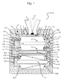
- Fig. 1 an arrangement for emitting light 10 with light elements, in particular LEDs 1, according to an embodiment of the present invention is shown from the side, wherein the LEDs 1 are coupled to a cooling system 100.
- the arrangement for emitting light 10 is located in a housing or a heat sink 8.
- the arrangement for emitting light 10 may extend in depth along the plane of the drawing, so that an elongate arrangement such as a profile rail with spaced individual LEDs or associations may be present as LEDs, which have been summarized by the LED 1 or considered.
- the light emission or radiation of the LED 1 extends through the light exit opening 4 (simplified as indicated by the rays emanating from the LED 1a as a bundle, shown).
- LED 1a As light sources, other light sources can be used in addition to the preferred LEDs.
- the light-emitting elements are like (the purely exemplary embodied as a hemisphere) LED 1, arranged on a support (substrate), for example on a circuit board or printed circuit board 3, mounted or soldered, for example.
- the circuit board 3 takes over in addition to the power supply via connecting wires, or pads (pads), the derivative or forwarding of the thermal power loss as the resulting in the light generation waste heat of the arrangement for light output.
- the heat exchange with the cooling system 100 is present over the printed circuit board 3 in a planar manner.
- the baffle plate 3 in the context of the usual operating frequencies and supply voltages
- the printed circuit board 3 is part of a region 5 which has a wall 7 which contains regions 7a and 7b.
- the printed circuit board 3 also adjoins the massive heat sink 8 in the region of the light exit or the light exit opening 4 by the way.
- the printed circuit board 3 can also overlap the heat sink 8, ie, in the heat sink 8, a recess can be considered recessed Corner, or a return (as a geometric opposite of a projection) are present, so that the circuit board 3 is offset upwards by its thickness.
- Projecting abutment or overlapping of the printed circuit board 3 in relation to the heat sink 8 can be provided, for example, if there is a ground connection to the printed circuit board or a directed electrical or thermal energy supply exchange between the printed circuit board 3 and the heat sink 8.
- the overlapping region at the points 3 a and 3 b can, however, also be restricted to the correspondingly adjacent corners (widened light exit opening 4) or a gap or an insulating layer between the circuit board 3 and the heat sink 8 can be present.
- the areas 7a and 7b, in Fig. 1 purely exemplary released, may be empty, but alternatively be filled from a thermally insulating or conductive material.
- a solvent circuit 15 and a coolant circuit 35 are separated by an intermediate view 17.
- the solvent circuit 15 and the coolant circuit 35 are arranged in the heat sink 8.
- recesses may be provided for the intermediate layer in conjunction with recesses for the solvent circuit 15 and the coolant circuit 35.
- the intermediate layer 17 can after Fig. 1
- the circumferential wall 19 can also be a layer, multiple layer or a series of layers (multilayer).
- the wall may be e.g. be at least one ply coated with a plastic or a catalyst (or vice versa), galvanized, painted, patterned or profiled.
- the catalyst supports the functions in the individual aggregates, for example, the evaporation or condensation of a liquid by providing a large surface area.
- the cavity 17a in the intermediate layer 17 can be designed either as an insulating layer or insulator or heat storage. If desired, the cavity 17a may have a thermal (heat capacity) influence on the coupling (i.e., degree of energy transfer) of the solvent circuit 15 and the coolant circuit 35.
- the wall 19 surrounding the intermediate layer 17 may be thermally permeable.
- the intermediate layer 17 may be embodied as a storage material or may comprise granules of a stone, or zeolite powder, chamotte, or fine sand.
- a solid such as a sintered ceramic, a dielectric or a magnetic material, such as ferrite, a Metal or an alloy or a gel-like thickened liquid are present, next to wood or brick, slate, granite or a magnet may be present.
- the intermediate layer 17 may be filled with a material having a high heat resistance (insulating material) with or without the free regions 17b or 17c.
- the cavity can be left empty, filled with a gas or with substances that have air pockets (foam, hard foam, wool).
- the intermediate layer 17 but also have buffer properties for the coolant or serve as a transfer layer with adhesion channels for the coolant between different, preferably adjacent components of the arrangement.
- an expeller 20 and an absorber 30 are arranged in the solvent circuit 15.
- a recess for the expeller 20 and the absorber 30 may be provided in the region 16 or both protruding components may be provided as part for insertion into a recess of the heat sink 8.
- the outlet 30b of the absorber 30 is connected to the inlet 20a of the expeller 20 via a connection 21, such as a pipe.
- a connection 21 such as a pipe.
- the first pump 23 solvent circuit compressor
- the expeller 20 and the absorber 30 are separated by a gap 32, which is purely exemplary designed as a cavity.
- a gap 32 which may also be permeable, however, the above applies, as in the intermediate layer 17, accordingly.
- a condenser 40 and an evaporator 50 is provided in the coolant circuit 35.
- the solvent circuit 15 and the coolant circuit 35 can also be arranged side by side or offset in height with appropriate wiring, wherein on the capacitor and a separate heat sink can be attached, conversely, a heat sink may have a recess for the capacitor.
- the capacitor 40 was in Fig. 1 represented as a trapezium, the diagonal conversion is intended to indicate the condensation or phase transitions from gaseous to liquid.
- phase transitions from (solid or) liquid to gaseous can also be referred to as a rich mixture (boiling solution).
- the outlet 20 c of the absorber 20 (here outlet 20 c was arranged in the expeller 20 above the outlet 20 b) is connected to the inlet of the condenser 40 a of the condenser 40 of the cooling circuit 35 via the line or connection 27.
- a conduit 43 having a valve 45 extends to the inlet 50a of the evaporator 50.
- connection 57 extends into the inlet 30c of the absorber 30 of the solvent circuit 15.
- a valve, a pump or a filter may also be located (outside the drawing).
- An essential feature of the cooling circuit 35 that is the arrangement with evaporator 50 and condenser 40, is that the coolant to be condensed comes externally, solely from the absorber 20. Furthermore, an intermediate region 42 between evaporator 50 and condenser 40 is provided. In the present case, the intermediate region 42 is again initially as a cavity in the Fig. 1 indicated, only enclosed by a wall 44 and empty inside.
- the statements made above for the intermediate layer 17 are valid.
- the intermediate region 42 can just as well be a so-called multi-functional layer, which therefore also permits, in addition to the insulation or heat storage, a fluid passage if it is permeable or designed as a semipermeable membrane.
- the condensed liquid also passes through the intermediate region 42, where it can be partly absorbed or diffused through it (liquid storage or buffer).
- the intermediate layer 42 may also have flexible walls with a wall thickness and thus be responsible for the transfer of functions with respect to temperature, heat radiation, pressure and fluid or matter. The above also applies to the intermediate layer 17.
- a region 46 is still provided, which is enclosed by a wall or layer 48.
- a recess for the condenser 40 may be provided in the region 46, or the condenser 40 may be provided as part for insertion into a recess of the heat sink 8.
- the present arrangement resembles a position-independent heat pipe or heat exchanger or a so-called heat pipe.
- any geometry is possible.
- Next succeeds an analogous use of an extended surface as a cooling surface by means of chemical adsorption.
- the present invention now uses the heat energy of the heatsinks to cool the light-emitting device and the LED light sources via the mechanism realized in the absorption refrigerator.
- the compressed refrigerant of a substance pair suitable for the temperature range e.g. Silica gel / water is evaporated by means of thermal drive in the expeller from the solution.
- the refrigerant After completion of the work, the refrigerant is condensed and absorbed again to complete the thermodynamic cycle.
- the cooling system is also mitigated by the system, wherein the arrangement according to Fig. 1 with short connections, allow low response time constants of the chiller to be dissipated in power output of the light emitting device.
- the present invention thus provides a simple, elegant and effective way to promote a well-tempered area of an LED array, in particular a luminaire with individual LED luminous elements of an LED luminaire by the combination of the arrangement for light emission with absorption chiller, an optically aesthetic To create overall appearance for the viewer, to reduce the heat sink and the material costs and also to contribute to the protection of climate and resources.
- the arrangement for emitting light can also be cooled down by means of the absorption chiller in the vicinity or integrated in a luminaire, or the required temperature differences can be achieved, possibly or even exceeded, as desired by the application or by the user.
Landscapes
- Engineering & Computer Science (AREA)
- General Engineering & Computer Science (AREA)
- Physics & Mathematics (AREA)
- Mechanical Engineering (AREA)
- Thermal Sciences (AREA)
- Led Device Packages (AREA)
- Arrangement Of Elements, Cooling, Sealing, Or The Like Of Lighting Devices (AREA)
- Cooling Or The Like Of Semiconductors Or Solid State Devices (AREA)
Abstract
Description
- Die vorliegende Erfindung betrifft eine Anordnung zur Lichtabgabe mit Leuchtelementen, insbesondere LEDs, und einem Kühlsystem, das mit den Leuchtelementen gekoppelt ist.
- Die Arbeitsweise einer LED-Leuchte bedingt, dass erhebliche Mengen an Wärme effektiv, schnell und zuverlässig abzuführen sind, um den Betrieb der Leuchten bzw. Leuchtmittel sicher zu stellen. Im Fall von LED-Anordnungen zur Lichtabgabe kann die erzeugte Wärme hauptsächlich nur durch Wärmeleitung von der Wärmequelle weggeführt werden. Meist wird die Wärme von einem Kühlkörper, der thermisch mit der LED-Anordnung gekoppelt ist, in die Umgebung mehr oder weniger abgestrahlt.
- Allerdings ist die Leistung eines Kühlkörpers hinsichtlich der Kühlleistung begrenzt. Einer kleinen, flachen und kompakten Bauform steht die erforderliche räumliche Überdimensionierung von Kühlkörpern unter der Berücksichtigung von Sicherheitsfaktoren oftmals im Wege.
- Daneben kann eine Sättigung des Kühlkörpers eintreten. Die Kühlung ist zunächst von der Temperaturdifferenz zwischen Umgebungstemperatur und Kühlkörpertemperatur abhängig. Im Betrieb kann sich bei laminarer Strömung eine Isolierschicht mit einem Temperaturgradienten an der Kühlkörperoberfläche ausbilden.
- Bei LEDs besteht eine starke Temperaturabhängigkeit der Lichtausbeute, zumal der Wirkungsgrad bei der Umsetzung der elektrischen Versorgungsenergie in Lichtabstrahlung in Ansehung der kleinräumigen Abmessungen noch verbessert werden kann. Der Hauptteil der elektrischen Versorgungsleistung muß weggekühlt werden, um Effizienz und Lebensdauer der LED-Lichtquellen zu erhalten.
- Im Ergebnis ist problematisch, wie bzw. wohin mit herkömmlichen Ansätzen zielführend die Ableitung von Verlustwärme einer Anordnung zur Lichtabgabe von einer einzelnen LED bis zu großflächigen Leuchtbändern wirklich zuverlässig funktionieren soll.
- Allerdings wird Voranstehendes noch schwieriger, wenn die Anforderungen an die Lichtintensität bzw. eine Leuchtdichte über eine Fläche weiter erhöht werden sollen, die eingebetteten LEDs entsprechend leistungsfähiger dimensioniert werden und ein ganzer Raum gleichmäßig hell auszuleuchten ist.
- Demgemäß wäre wünschenswert, eine Anordnung derart zu schaffen, dass eine Lichtabgabe durch niedrige Arbeitstemperaturen erhöht und die Wärmeabgabe unter Vermeidung der obengenannten Nachteile wirkungsvoll verbessert werden kann.
- Vorstehende Aufgabe wird durch eine Anordnung zur Lichtabgabe mit Leuchtelementen gemäß dem Anspruch 1 und durch ein Verfahren zur Kühlung zur Verwendung für eine Anordnung zur Lichtabgabe mit Leuchtelementen gemäß dem Anspruch 10 gelöst. Vorteilhafte Weiterbildungen sind Gegenstand der abhängigen Ansprüche.
- Demgemäß ist nach einem ersten Aspekt eine Anordnung zur Lichtabgabe mit Leuchtelementen vorgesehen, insbesondere LEDs, und einem thermisch mit mindestens einem Leuchtelement gekoppelten Kühlsystem. Die Anordnung zur Lichtabgabe und das Kühlsystem sind derart ausgestaltet, dass das Kühlsystem eine Absorptions-Kältemaschine enthält.
- Indem das Kühlsystem geeignet mit der LED-Anordnung thermisch gekoppelt ist, wird eine zuverlässige Möglichkeit der Bereitstellung der Verlustwärme für die Verwendung in einer Anordnung zur Absorptionskühlung ermöglicht. Die Abwärme der Anordnung zur Lichtabgabe kann zum Beispiel über eine massive Platte an das Kühlsystem weitergeben werden.
- Weiter gelingt zuverlässig, die zunächst eher punktförmig, gerichtet und konzentriert entstehende Abwärme der LED sicher und schnellst möglich abzuleiten.
- Bei Verwendung von wärmetragfähigen Kühlflüssigkeiten, bevorzugt kompressiblen bzw. verdampfenden Medien oder Flüssigkeitsgemischen, erhöht sich die Leistungsfähigkeit jedes einzelnen Elements der Beleuchtungsanordnung erheblich. Die Risiken einer starken Temperaturtrift entfallen. Die Dimensionierung der Kühlung gelingt zuverlässig und haltbar.
- Sodann kann die Wärmeableitung auch in an sich gewohnter Weise über die Leiterplatte bzw. Platine über Metallisierungen als auch anliegende Kühlprofile erfolgen, die mit Teilen des Kühlsystems thermisch verbunden sind und die Anordnung zur Lichtabgabe durchziehen.
- Die Leiterplatte, die die LEDs trägt und umfangreiche Aufgaben zu bewerkstelligen hat, wird bei ihrer hohen thermischen Verantwortung für die Anordnung mit Leuchtelementen unterstützt und in ihrer Herstellung vereinfacht.
- Die besonders gute Kühlung der Anordnung zur Lichtabgabe mittels Kühlmedien im Zusammenhang mit Kreisprozessen bei Kältemaschinen erlaubt es, die erreichbaren Lichtströme pro Flächeneinheit erheblich zu erhöhen. Die gewohnte Zuverlässigkeit und etwaige Sicherheitsabschläge können beibehalten werden.
- Vorstehende LED-Anordnung besitzt damit in jeder Hinsicht eine hohe Verfügbarkeit, Einsatzfähigkeit und Betriebssicherheit. Die Anordnung zur Lichtabgabe kann mit einer großen Strahlungsleistung wirtschaftlich, günstig und einfach hergestellt werden.
- Hinsichtlich der Bauform der Anordnung zur Lichtabgabe können modulare oder kompakte Ausführungen mit günstigen baulichen Abmessungen erreicht werden.
- Weiterhin besteht die Kompatibilität zu üblichen Fertigungsprozessen der einzelnen mechanischen Komponenten der Anordnung zur Lichtabgabe, einschließlich der Leiterplatten- und Elektronikfertigung.
- Nach vorstehendem ersten Aspekt der Erfindung wird in bemerkenswerter Weise die von der LED-Einheit erzeugte, unter Umständen sehr hohe Verlustleistung im thermischen Spektralbereich abgeführt und in der Absorptions-Kältemaschine als Antrieb weiterverwendet.
- Von anderen Baugruppen wie zum Beispiel dem Lichtaustrittelement oder einer Optik wird die Verlustleistung ferngehalten, gerade wenn alternative Optiken mit flexiblen Werkstoffen eingesetzt werden, die niedrigere Temperaturen bevorzugen. Hohe Lichtleistungen können sicher bereitgestellt, übertragen und wirkungsvoll gesteuert, z.B. gedimmt, werden. Weiterhin wird die Elektronik zur Ansteuerung der LEDs von externer Wärmebeaufschlagung befreit, dort erzeugte Verlustleistung der Leistungsbauelemente wird abgeführt.
- Das Leuchtmittel, insbesondere jede einzelne LED, wird wohltemperiert im optimalen Arbeitsbereich gehalten. Die Abwärme kann besonders vorteilhaft und zuverlässig abgeführt werden.
- Im Ergebnis kann demgemäß der Betrieb der Anordnung mit Leuchtelementen durch das Kühlsystem mit einer Absorptions-Kältemaschine so verbessert werden, dass ein synergetischer Effekt über mehrere Systemebenen hindurch in der Optimierung der Gesamtenergiebilanz eintritt.
- Nach einem zweiten Aspekt ist die vorliegende Anordnung zur Lichtabgabe dadurch gekennzeichnet, dass die Absorptions-Kältemaschine derart ausgestaltet ist, dass ein Lösemittelkreislauf und ein Kühlmittelkreislauf verbunden sind und ein verdichtbares Kühlmittel vorliegt.
- Nach einem dritten Aspekt ist die Anordnung zur Lichtabgabe gemäß dem zweiten Aspekt dadurch gekennzeichnet, dass das Kühlmittel aus einem für die Absorptions-Kältemaschine geeigneten Stoffpaar, wie zum Beispiel Silikagel/Wasser gebildet wird.
- Ferner können für das Kühlmittel bzw. verdichtetes Kältemittel auch andere geeignete Kombinationen wie Ammoniak/Wasser oder Zeolith/Wasser, jeweils optional mit Additiven, beispielsweise zur Verdunstungsförderung oder eventuell auch Gase bzw. Plasmen eingesetzt werden.
- Nach einem vierten Aspekt ist die Anordnung zur Lichtabgabe gemäß dem zweiten bis dritten Aspekt dadurch gekennzeichnet, dass der Lösemittelkreislauf zwei benachbarte Kammern aufweist, die als Austreiber und als Absorber ausgebildet und über ein erstes Ventil verbunden sind. Der Austreiber und der Absorber können sich in einem Behälter (beispielsweise zwei Halbschalen) befinden und über einen Zwischenhohlraum, poröse Zwischenwände bzw. eine Isolierung beabstandet sein. Bei dem Ventil kann auch ein Magnetventil oder ein Steuerschieber bzw. Stellzylinder in Verbindung mit einer Regelung vorgesehen sein.
- Nach einem fünften Aspekt ist die Anordnung zur Lichtabgabe gemäß dem zweiten bis vierten Aspekt dadurch gekennzeichnet, dass der Kühlmittelkreislauf zwei benachbarte Kammern aufweist, die als Kondensator und Verdampfer ausgebildet und über ein zweites Ventil verbunden sind. Der Kondensator und der Verdampfer können sich in einem Behälter befinden und über einen Zwischenhohlraum, poröse Zwischenwände bzw. eine Isolierung beabstandet sein. Bei dem Ventil kann ein Magnetventil oder Stelltrieb mit einer Regelung vorgesehen sein.
- Nach einem sechsten Aspekt ist die Anordnung zur Lichtabgabe gemäß dem zweiten bis fünften Aspekt dadurch gekennzeichnet, dass die beiden Kammern im Lösemittelkreislauf über eine Leitung verbunden ist, in der sich eine Pumpe befindet. Bei der Pumpe liegt im Rahmen der Kältemaschine bevorzugt ein Verdichter vor. Allerdings kann für einen sog. thermischen Transformator statt oder neben der Pumpe auch eine Drossel vorliegen. Unter dem Lösemittel soll ein gelöstes bzw. in Lösung gegangenes Kühlmittel bzw. Kältemittel, modellhaft als Wärme lösendes Mittel, verstanden werden.
- Nach einem siebten Aspekt ist die Anordnung zur Lichtabgabe gemäß dem sechsten Aspekt dadurch gekennzeichnet, dass der Lösemittelkreislauf und der Kühlmittelkreislauf durch Kammern in einem Kühlkörper mit Zwischenwänden beabstandet sind. Vorstehende Zwischenwände können aus einem wärmeleitenden oder isolierenden Material gefertigt sein oder Hohlraum einschließlich Vakuum aufweisen.
- Nach einem achten Aspekt ist die Anordnung zur Lichtabgabe gemäß dem siebten Aspekt dadurch gekennzeichnet, dass die Abwärme der Leuchtelemente in der als Austreiber ausgebildeten Kammer des Lösemittelkreislaufs als thermischer Antrieb vorliegt.
- Nach einem neunten Aspekt ist die Anordnung zur Lichtabgabe gemäß dem achten Aspekt dadurch gekennzeichnet, dass sich die Absorptions-Kältemaschine in einem Gehäuse mit den Leuchtelementen befindet. Vorgenanntes Gehäuse kann bevorzugt als Kühlkörper mit Oberflächenprofilierung und Lamellen ausgeführt sein. Die Außenwand des Kühlkörpers kann eine Riffelung bzw. Vorsprünge und Ausnehmungen aufweisen. Im Inneren kann der Kühlkörper auch blockartig mit Einrichtungen, Kammern oder Vorrichtungen zum Einlegen, Rasten oder Einklemmen von Leitungen (snap-in) ausgestaltet sein. In beispielsweise zwei lösbar verbundenden bzw. fügbaren Halblöcken bzw. Gegenstücken oder Halbschalen können die Teile der Anordnung zur Lichtabgabe, einschließlich mindestens einer Leiterplatte und der Absorptions-Kältemaschine nach den obenstehenden Aspekten untergebracht sein. Im Kühlkörper bzw. in den angrenzenden Innenflächen können Ausnehmungen bzw. Kanäle für Leitungen mit danebenliegenden Dichtflächen für die Zwischenverbindungen zwischen den Bestandteilen der Anordnung zur Lichtabgabe vorgesehen sein.
- Nach einem zehnten Aspekt ist ein Verfahren zur Kühlung einer Anordnung zur Lichtabgabe mit Leuchtelementen, insbesondere LEDs, mit Hilfe eines thermisch mit den Leuchtelementen gekoppelten Kühlsystems dadurch gekennzeichnet, dass die Wärme eines mit den Leuchtelementen gekoppelten Kühlkörpers den Austreiber einer Absorptions-Kältemaschine beheizt.
- Vorstehendes Leuchtenbauteil kann auch als Behälter, Kessel, Tank oder dreidimensional ausgeformte schmale Hohlkammer ausgeführt sein. Im Fall eines Reflektors kann an der Seite, die der Lichtquelle zugewandt ist, eine optisch glänzende Oberfläche ausgebildet sein kann.
- Bei der LED-Anordnung der vorliegenden Erfindung ist nach einer bevorzugten Ausführungsform die thermische Kopplung der LEDs mit einer Absorptions-Kältemaschine im weitesten Sinne vorgesehen. Wie bereits angesprochen, erlaubt die Eingliederung der Kühlung in die Beleuchtung und umgekehrt, auf den ersten Blick völlig wesensverschiedene Teile, Vorteile bei der Energieverteilung. Der Schwerpunkt der Kopplung liegt in der Kombination der Kältemaschine mit der LED-Anordnung. Die herausragenden Vorteile der vorliegenden Erfindung bestehen also im Bereich der Überlappung, als Schnittmenge der Merkmale bzw. an der Schnittstelle zwischen dem Bereich der Verbindung von der Lichterzeugung und der Kälteerzeugung.
- Im Ergebnis wird die LED-Anordnung zur Lichtabgabe mit Leuchtelementen mit Hilfe der Absorptions-Kältemaschine in die Lage versetzt, hohe Lichtleistungen sicher umzusetzen. Die LED-Anordnung wird somit noch zuverlässiger, über lange Zeit noch wartungsfreier und vor thermischer Ermüdung, vorzeitiger Alterung, plötzlichem Betriebsausfall oder Überhitzung bewahrt.
- Nachfolgend soll die Erfindung anhand der beiliegenden Zeichnung näher erläutert werden. Es zeigen:
- Fig. 1
- die Ansicht einer erfindungsgemäßen Anordnung zur Lichtabgabe mit verbundenem Kühlsystem.
- In
Fig. 1 ist eine Anordnung zur Lichtabgabe 10 mit Leuchtelementen, insbesondere LEDs 1, entsprechend einer Ausführungsform der vorliegenden Erfindung von der Seite dargestellt, wobei die LEDs 1 mit einem Kühlsystem 100 gekoppelt sind. - Die Anordnung zur Lichtabgabe 10 befindet sich in einem Gehäuse bzw. einem Kühlkörper 8. Die Anordnung zur Lichtabgabe 10 kann sich entlang der Zeichnungsebene in die Tiefe erstrecken, so dass eine längliche Anordnung wie eine Profilschiene mit beabstandeten einzelnen LEDs oder Verbänden als LEDs vorliegen mag, die durch die LED 1 zusammengefasst wurden bzw. betrachtet werden.
- Die Lichtabgabe bzw. Abstrahlung der LED 1 verläuft durch die Lichtsaustrittsöffnung 4 (vereinfacht anhand der von der LED ausgehenden Strahlen 1a als Bündel angedeutet, dargestellt). Als Leuchtmittel können neben den bevorzugten LEDs auch andere Lichtquellen zum Einsatz kommen.
- Die Leuchtelemente sind wie (die rein beispielshaft als Hemisphäre ausgeführte) LED 1, auf einem Träger (Substrat), beispielsweise auf einer Platine oder Leiterplatte 3 angeordnet, montiert oder beispielsweise verlötet.
- Die Leiterplatte 3 übernimmt neben der Energieversorgung über Anschlußdrähte, oder Anschlußfelder (pads), die Ableitung bzw. Weiterleitung der thermischen Verlustleistung als die bei der Lichterzeugung entstehende Abwärme der Anordnung zur Lichtabgabe.
- Vorliegend liegt der Wärmeaustausch mit dem Kühlsystem 100 flächig über die Leiterplatte 3 vor. Vereinfacht sei die Leitplatte 3 (im Rahmen der üblichen Betriebsfrequenzen und Versorgungsspannungen) als elektrisch isolierend und (im Rahmen der zu übertragenden Energien) als thermisch leitend angenommen. Die Leiterplatte 3 ist Teil eines Bereiches 5, der eine Wandung 7 aufweist, die Bereiche 7a und 7b enthält.
- Teilweise grenzt die Leiterplatte 3 an den Stellen 3a und 3b auch an den massiven Kühlkörper 8 im Bereich des Lichtsaustritts bzw. der Lichtaustrittsöffnung 4. Übrigens kann die Leiterplatte 3 auch den Kühlkörper 8 sozusagen überlappen, d.h., in dem Kühlkörper 8 kann eine Ausnehmung als zurückgesetzte Ecke, bzw. ein Rücksprung (als geometrisches Gegenteil eines Vorsprungs) vorliegen, so dass die Leiterplatte 3 nach oben um ihre Dicke versetzt ist.
- Vorstehendes Angrenzen oder Überlappen der Leiterplatte 3 in Beziehung mit dem Kühlkörper 8 kann beispielsweise vorgesehen sein, falls eine Masseverbindung mit der Leiterplatte oder ein gerichteter elektrischer bzw. thermischer Energieversorgungsaustausch zwischen Leiterplatte 3 und Kühlkörper 8 vorliegt.
- Gleichfalls versteht sich, dass der Überlappungsbereich an den Stellen 3a und 3b sich aber auch lediglich auf die entsprechend benachbarten Ecken beschränken kann (verbreiterte Lichtaustrittsöffnung 4) oder ein Abstand bzw. eine Lücke oder eine Isolierschicht zwischen der Leiterplatte 3 zu dem Kühlkörper 8 vorliegen kann.
- Die Bereiche 7a und 7b, in
Fig. 1 rein beispielhaft freigelassen, können leer sein, aber alternativ auch aus einem thermisch isolierenden bzw. leitenden Material gefüllt sein. - Im Rahmen des Kühlsystems 100 sind ein Lösemittelkreislauf 15 und ein Kühlmittelkreislauf 35 durch eine Zwischensicht 17 getrennt. Der Lösemittelkreislauf 15 und der Kühlmittelkreislauf 35 sind in dem Kühlkörper 8 angeordnet. Im Kühlkörper 8 können Ausnehmungen für die Zwischenschicht in Verbindung mit Ausnehmungen für den Lösemittelkreislauf 15 und den Kühlmittelkreislauf 35 vorgesehen sein.
- Die Zwischenschicht 17 kann nach
Fig. 1 zum Beispiel ein Element sein, das einen Zwischenhohlraum 17a aufweist (als nach rechts verlaufende Schraffur gezeigt), wobei der Zwischenhohlraum 17a durch eine herum bzw. umlaufende Wand 19 definiert bzw. abgegrenzt ist. Rechts und links um den Zwischenhohlraum 17a sind freie Bereiche 17b und 17c dargestellt. - Die umlaufende Wand 19 kann beispielshalber - und das gilt für alle Wände in der gesamten Anordnung zur Lichtabgabe 10 -auch eine Schicht, Mehrfachschicht oder eine Folge von Lagen (Multilayer) sein. Falls die Wand beispielsweise aus Metall ist, kann sie z.B. mindestens einlagig mit einem Kunststoff oder einem Katalysator überzogen (oder umgekehrt), galvanisiert, lackiert, bemustert oder profiliert sein. Der Katalysator unterstützt die Funktionen in den einzelnen Aggregaten, beispielsweise das Verdunsten oder Kondensieren einer Flüssigkeit durch Bereitstellung einer großen Oberfläche.
- Der Hohlraum 17a in der Zwischenschicht 17 kann entweder als Isolierschicht bzw. Isolator oder Wärmespeicher ausgeführt sein. Wenn erwünscht, kann der Hohlraum 17a in thermischer Hinsicht (Wärmekapazität) einen Einfluß auf die Kopplung bzw. Abkopplung (d.h. Grad der Energieübertragung) des Lösemittelkreislaufes 15 und des Kühlmittelkreislaufes 35 haben.
- Für einen Wärmespeicher oder -puffer kann die um die Zwischenschicht 17 umlaufende Wand 19 thermisch durchlässig sein. Im Inneren des Hohlraums 17a kann die Zwischenschicht 17 als Speicherstoff ausgeführt sein bzw. ein Granulat aus einem Stein, bzw. Zeolitpulver, Schamot, oder feinem Sand aufweisen. Daneben kann als Füllung des Hohlraums ein Feststoff, beispielsweise eine Sinterkeramik, ein dielektrischer oder ein magnetischer Werkstoff, etwa Ferrit, ein Metall oder eine Legierung oder eine Gel-artige verdickte Flüssigkeit vorliegen, daneben kann Holz oder Ziegel, Schiefer, Granit oder ein Magnet vorhanden sein.
- Für einen Isolator kann die Zwischenschicht 17 mit oder ohne die freien Bereiche 17b bzw. 17c mit einem Stoff mit einem hohen Wärmewiderstand (Isolierstoff) gefüllt sein. Vorstehend kann der Hohlraum leer bleiben, mit einem Gas oder mit Stoffen, die Lufteinschlüsse aufweisen, gefüllt sein (Schaumstoff, Hartschaum, Wolle).
- Gegebenenfalls kann die Zwischenschicht 17 aber auch Puffereigenschaften für das Kühlmittel aufweisen oder als Transferschicht mit Adhäsionskanälen für das Kühlmittel zwischen verschiedenen, bevorzugt benachbarten Bauteilen der Anordnung dienen.
- Im Lösemittelkreislauf 15 sind ein Austreiber 20 und ein Absorber 30 angeordnet.
- Um den Austreiber 20 und den Absorber 30 herum ist noch ein Bereich 16 vorgesehen, der von einer Wandung 18 umschlossen ist.
- Beispielsweise kann im Bereich 16 eine Ausnehmung für den Austreiber 20 und den Absorber 30 vorgesehen sein bzw. können beide vorstehenden Bauteile als Teil zum Einschieben in eine Ausnehmung des Kühlkörpers 8 vorgesehen sein.
- Der Auslass 30b des Absorbers 30 ist über eine Verbindung 21, etwa eine Leitung, mit dem Einlass 20a des Austreibers 20 verbunden. Für die Förderung des Kühlmittels im Lösemittelkreislauf 15 durch die Verbindung 21 liegt die erste Pumpe 23 (Lösemittelkreislaufverdichter) vor.
- Am Auslass 20b des Austreibers 20 liegt eine Leitung bzw. Verbindung 21a zurück zum Einlass 30a des Absorbers 30 vor, wobei ein Ventil 25 in der Verbindung 21a vorgesehen ist.
- Der Austreiber 20 und der Absorber 30 sind durch einen Zwischenraum 32 getrennt, der rein beispielshaft als Hohlraum ausgeführt ist. Für den Zwischenraum 32, der auch durchlässig sein kann, gilt allerdings das oben Gesagte, wie bei der Zwischenschicht 17, entsprechend.
- In der Zeichnung, rein beispielshaft unter dem Lösemittelkreislauf 15 liegend dargestellt, ist im Kühlmittelkreislauf 35 ein Kondensator 40 und ein Verdampfer 50 vorgesehen. Statt untereinander kann der Lösemittelkreislauf 15 und der Kühlmittelkreislauf 35 auch nebeneinander oder höhenversetzt mit entsprechender Leitungsführung angeordnet werden, wobei an dem Kondensator auch ein eigener Kühlkörper angebracht sein kann bzw. umgekehrt ein Kühlkörper eine Ausnehmung für den Kondensator aufweisen kann.
- Der Kondensator 40 wurde in
Fig. 1 wie ein Trapez dargestellt, wobei die Diagonale die Wandlung die Kondensation bzw. stattfindende Phasenübergange von gasförmig nach flüssig andeuten soll. - Bei dem Verdampfer 50 gilt Vorstehendes entsprechend mit umgekehrter Diagonale. Vorstehend können entsprechende Phasenübergängen von (fest bzw.) flüssig nach gasförmig auch als reiches Gemisch (siedende Lösung) bezeichnet werden.
- Der Auslass 20c des Absorbers 20 (hier wurde Auslass 20c im Austreiber 20 über dem Auslass 20b angeordnet) ist mit dem Einlass des Kondensators 40a des Kondensators 40 des Kühlkreislaufes 35 über die Leitung bzw. Verbindung 27 verbunden. Dort kann sich übrigens (außerhalb der Zeichnung) auch ein Ventil, eine Pumpe oder ein Filter befinden. Vom Auslass 40b des Kondensators 40 verläuft eine Leitung bzw. Verbindung 43 mit Ventil 45 zum Einlass 50a des Verdampfers 50.
- Weiterhin verläuft vom Auslass 50b des Verdampfers 50 eine Leitung bzw. Verbindung 57 in den Einlass 30c des Absorbers 30 des Lösemittelkreislaufes 15. In der Verbindung 57 kann sich übrigens (außerhalb der Zeichnung) auch ein Ventil, eine Pumpe oder ein Filter befinden.
- Ein wesentliches Merkmal des Kühlkreislaufs 35, also der Anordnung mit Verdampfer 50 und Kondensator 40, ist, dass das zu kondensierende Kühlmittel extern, alleinig aus dem Absorber 20 stammt. Ferner ist ein Zwischenbereich 42 zwischen Verdampfer 50 und Kondensator 40 vorgesehen. Vorliegend ist der Zwischenbereich 42 wiederum zunächst als ein Hohlraum in der
Fig. 1 angedeutet, lediglich von einer Wandung 44 umschlossen und innen leer. - Allerdings gilt weiterhin für den Zwischenbereich 42, der jeweils auch als Isolierschicht bzw. Wärmespeicherschicht ausgelegt, bzw. gefüllt sein kann, wiederum das oben bereits für die Zwischenschicht 17 Gesagte.
- Darüberhinaus kann auch der Zwischenbereich 42 genauso gut auch eine sog. Mehrfunktionsschicht sein, die also neben der Isolierung bzw. Wärmespeicherung auch bzw. dennoch einen Flüssigkeitsdurchgang erlaubt, falls sie durchlässig bzw. als semipermeable Membran ausgeführt ist. Beispielsweise kann sich anbieten, dass die kondensierte Flüssigkeit auch durch den Zwischenbereich 42 hindurchgeht, dort teilweise aufgesaugt oder verzögert hindurch diffundieren kann (Flüssigkeitsspeicher bzw. -puffer).
- Die Zwischenschicht 42 kann schließlich auch flexible Wände mit einer Wanddicke aufweisen und somit für die Übertragung von Funktionen bezüglich Temperatur, Wärmestrahlung, Druck und Flüssigkeit bzw. Materie zuständig sein. Vorstehendes gilt auch für die Zwischenschicht 17.
- Um den Kondensator 40 herum ist noch ein Bereich 46 vorgesehen, der von einer Wandung oder Schicht 48 umschlossen ist. Beispielsweise kann im Bereich 46 eine Ausnehmung für den Kondensator 40 vorgesehen sein bzw. der Kondensator 40 als Teil zum Einschieben in eine Ausnehmung des Kühlkörpers 8 vorgesehen sein.
- Im Ergebnis ähnelt (vereinfacht ausgedrückt) die vorliegende Anordnung einem lageunabhängigen Wärmerohr bzw. -übertrager bzw. einer sog. Heatpipe. Vorstehend ist allerdings eine beliebige Geometrie möglich. Weiter gelingt eine analoge Nutzung einer ausgedehnten Oberfläche als Kühlfläche mittels chemischer Adsorption.
- Bei der Funktion der vorstehenden Anordnung zur Lichtabgabe nutzt die vorliegende Erfindung nun die Wärmeenergie der Kühlkörper, um über den Mechanismus, der in Absorptions-Kältemaschine verwirklich wird, die Anordnung zur Lichtabgabe bzw. die LED-Lichtquellen, zu kühlen.
- Das verdichtete Kältemittels eines Stoffpaares, dass für den Temperaturbereich geeignet ist, z.B. Silikagel/Wasser wird mittels thermischem Antrieb im Austreiber aus der Lösung verdampft.
- Nach geleisteter Arbeit wird das Kältemittel zum Abschluß des thermodynamischen Kreisprozesses wieder kondensiert und absorbiert.
- Vorstehendes geschieht vorzugsweise in zwei geschlossenen Kreisläufen mit kältemittelreicher und kältemittelarmer Lösung. Denkbar wäre wohl auch, den Lösemittelkreislauf 15 mit dem Kühlmittelkreislauf 35 zu überlappen bzw. eventuell den gesamten Kühlvorgang in einem Kreislauf, in einer Kammer oder in einer Kammer mit Unterteilungen, Abschnitten bzw. verschiedenen Temperatur, Konzentrations- und Druckzonen zu realisieren.
- Dadurch, dass die Wärmequelle selbst gekühlt wird, stellt sich bei vorstehendem Kühlprozess ein Gleichgewicht ein, das durch verschiedene Parameter beeinflusst werden kann und somit sinnvoll stabil eingestellt bzw. geregelt werden kann.
- Besonders günstig ist, dass je heißer die Quelle ist, desto höher die Kühlleistung wird. Somit gelingt, besonders vorteilhaft, eine optimale Kühlung der Anordnung zur Lichtabgabe, die nämlich leistungsangepasst ist.
- Wenn also die LED in ihrer Leistung geregelt oder gedimmt wird, wird auch die Kühlung vom System schritthaltend mitverändert, wobei sich bei der Anordnung nach
Fig. 1 mit kurzen Verbindungen geringe Antwort-Zeitkonstanten der Kältemaschine auf Verlustleistungsänderungen der Anordnung zur Lichtabgabe erreichen lassen. - Durch vorstehende erneute Nutzung der Abwärme im Rahmen eines Kühlsystems auf der Basis der Absorptionskältemaschine entsteht im Endeffekt eine Effizienzsteigerung. Vorstehend gelingt also eine verbessere Lichtausbeute bei gleichem Energieeinsatz, welches weiter durch geringere Kühlkörpervolumina belohnt wird und sich in einer Gewichtsersparnis erkenntlich zeigt. Zudem erfolgt die Kühlung unmerklich und vollkommen geräuschlos.
- Mit der vorliegenden Erfindung wird somit durch die Kombination der Anordnung zur Lichtabgabe mit Absorptionskältemaschine eine einfache, elegante und wirkungsvolle Möglichkeit geschaffen, einen wohltemperierten Bereich einer LED-Anordnung, insbesondere einer Leuchte mit einzelnen LED-Leuchtelementen einer LED-Leuchte zu fördern, eine optisch ästhetische Gesamterscheinung für den Betrachter zu erzeugen, den Kühlkörper und die Materialkosten zu reduzieren und darüberhinaus einen Beitrag für den Schutz von Klima und Ressourcen zu leisten.
- Darüber hinaus sind die Möglichkeiten bei der Lichtabgabe der LED-Anordnung auch bei flächenartigen Beleuchtungsanordnungen durch direkte Kühlung auch unter hohen Lichtströmen so gut, dass LED-Einheiten aufgrund der mit geringem Aufwand gut dimensionierbaren und schnell verfügbaren Kühlreserven (anpassende Kühlung) selbst bei hohen Umgebungstemperaturen und maximalen Lichtleistungen bei optimalen Temperaturen betrieben und in ihren Eigenschaften in Verbänden aus Leuchtbändern oder als Array aus LED-Arrays optimal organisiert werden können.
- Eindrucksvoll kann gerade mittels der Absorptionskältemaschine in der Nähe oder integriert in einer Leuchte die Anordnung zur Lichtabgabe auch soweit heruntergekühlt werden, bzw. die geforderten Temperaturdifferenzen erreicht, gegebenenfalls oder auch übertroffen werden, wie von der Anwendung oder vom Anwender gewünscht.
- Schließlich liegt durch die Abgabe der Wärme mittels der erfindungsgemäßen Ausgestaltung eine sichere und zuverlässige Wärmeableitung vor, die die LED-Anordnung in allen Fällen, auch bei erhöhter Lichtausgabe geeignet entlastet und nach allem eine optimierte Gesamtanordnung erschafft.
Claims (10)
- Anordnung zur Lichtabgabe (10) mit Leuchtelementen, insbesondere LEDs (1), und einem thermisch mit den Leuchtelementen (1) gekoppelten Kühlsystem (100),
dadurch gekennzeichnet,
dass das Kühlsystem (100) eine Absorptions-Kältemaschine (20, 30, 40, 50) beinhaltet. - Anordnung zur Lichtabgabe (10) gemäß Anspruch 1,
dadurch gekennzeichnet,
dass die Absorptions-Kältemaschine derart ausgestaltet ist, dass ein Lösemittelkreislauf (15) und ein Kühlmittelkreislauf (35) verbunden sind und ein verdichtbares Kühlmittel vorliegt. - Anordnung zur Lichtabgabe (10) gemäß Anspruch 2,
dadurch gekennzeichnet,
dass das Kühlmittel aus einem für die Absorptions-Kältemaschine geeigneten Stoffpaar, wie zum Beispiel Silikagel/Wasser gebildet wird. - Anordnung zur Lichtabgabe (10) gemäß Anspruch 2 bis 3,
dadurch gekennzeichnet,
dass der Lösemittelkreislauf (15) zwei benachbarte Kammern aufweist, die als Austreiber (20) und als Absorber (30) ausgebildet und über ein erstes Ventil (25) verbunden sind. - Anordnung zur Lichtabgabe gemäß einem der Ansprüche 2 bis 4,
dadurch gekennzeichnet,
dass der Kühlmittelkreislauf (35) zwei benachbarte Kammern aufweist, die als Kondensator (40) und Verdampfer (50) ausgebildet und über ein zweites Ventil (45) verbunden sind. - Anordnung zur Lichtabgabe (10) gemäß einem der Ansprüche 2 bis 5,
dadurch gekennzeichnet,
dass die beiden Kammern im Lösemittelkreislauf (15) über eine Leitung (21) verbunden sind, in der sich eine Pumpe (23) befindet. - Anordnung zur Lichtabgabe (10) gemäß Anspruch 6,
dadurch gekennzeichnet,
dass der Lösemittelkreislauf (15) und der Kühlmittelkreislauf (15) durch Kammern in einem Kühlkörper (8) mit Zwischenwänden (32, 17, 42) beabstandet sind. - Anordnung zur Lichtabgabe (10) gemäß Anspruch 7,
dadurch gekennzeichnet,
dass die Abwärme der Leuchtelemente (1) in der als Austreiber (20) ausgebildeten Kammer des Lösemittelkreislaufs (15) als thermischer Antrieb vorliegt. - Anordnung zur Lichtabgabe (10) gemäß Anspruch 8,
dadurch gekennzeichnet,
dass sich die Absorptions-Kältemaschine (100) in einem Gehäuse (8) mit den Lichtquellen (1) befindet. - Verfahren zur Kühlung (100) einer Anordnung zur Lichtabgabe (10) mit Leuchtelementen (1), insbesondere LEDs, mit Hilfe eines thermisch mit den Leuchtelementen (1) gekoppelten Kühlsystems (100, 20, 30, 40, 50),
dadurch gekennzeichnet,
dass die Wärme eines mit den Lichtquellen (1) gekoppelten Kühlkörpers (8) den Austreiber (20) einer Absorptions-Kältemaschine (100) beheizt.
Applications Claiming Priority (1)
| Application Number | Priority Date | Filing Date | Title |
|---|---|---|---|
| DE202009007810U DE202009007810U1 (de) | 2009-06-04 | 2009-06-04 | Anordnung zur Lichtabgabe mit Leuchtelementen und damit gekoppeltem Kühlsystem |
Publications (3)
| Publication Number | Publication Date |
|---|---|
| EP2273215A2 true EP2273215A2 (de) | 2011-01-12 |
| EP2273215A3 EP2273215A3 (de) | 2011-03-16 |
| EP2273215B1 EP2273215B1 (de) | 2013-08-14 |
Family
ID=42617492
Family Applications (1)
| Application Number | Title | Priority Date | Filing Date |
|---|---|---|---|
| EP10164962.2A Not-in-force EP2273215B1 (de) | 2009-06-04 | 2010-06-04 | Anordnung zur Lichtabgabe mit Leuchtelementen und damit gekoppeltem Kühlsystem |
Country Status (2)
| Country | Link |
|---|---|
| EP (1) | EP2273215B1 (de) |
| DE (1) | DE202009007810U1 (de) |
Families Citing this family (1)
| Publication number | Priority date | Publication date | Assignee | Title |
|---|---|---|---|---|
| DE102016224064A1 (de) | 2016-12-02 | 2018-06-07 | Eaton Protection Systems Ip Gmbh & Co. Kg | Elektrisches/Elektronisches Betriebsmittel, Verfahren zur Kühlung und Überwachung des Betriebsmittels sowie Sicherheitsschalteinrichtung |
Family Cites Families (7)
| Publication number | Priority date | Publication date | Assignee | Title |
|---|---|---|---|---|
| DE10324300B4 (de) * | 2003-05-21 | 2006-06-14 | Thomas Dr. Weimer | Thermodynamische Maschine und Verfahren zur Aufnahme von Wärme |
| CN100464411C (zh) * | 2005-10-20 | 2009-02-25 | 富准精密工业(深圳)有限公司 | 发光二极管封装结构及封装方法 |
| US20070102033A1 (en) * | 2005-11-04 | 2007-05-10 | Universal Media Systems, Inc. | Dynamic heat sink for light emitting diodes |
| AT503715B1 (de) * | 2006-09-18 | 2007-12-15 | Hans-Peter Dr Bierbaumer | Kühlgerät |
| DE102007038911A1 (de) * | 2007-08-17 | 2009-02-19 | Osram Gesellschaft mit beschränkter Haftung | Kühlvorrichtung und Beleuchtungseinrichtung |
| DE102007038909B4 (de) * | 2007-08-17 | 2021-07-15 | Osram Gmbh | Wärmeleitrohr und Anordnung mit Wärmeleitrohr |
| KR100854084B1 (ko) * | 2007-09-10 | 2008-08-25 | 주식회사 썬라이팅 | 파워 발광다이오드가 내장된 조명등의 냉각장치 |
-
2009
- 2009-06-04 DE DE202009007810U patent/DE202009007810U1/de not_active Expired - Lifetime
-
2010
- 2010-06-04 EP EP10164962.2A patent/EP2273215B1/de not_active Not-in-force
Non-Patent Citations (1)
| Title |
|---|
| None |
Also Published As
| Publication number | Publication date |
|---|---|
| EP2273215A3 (de) | 2011-03-16 |
| EP2273215B1 (de) | 2013-08-14 |
| DE202009007810U1 (de) | 2010-11-11 |
Similar Documents
| Publication | Publication Date | Title |
|---|---|---|
| DE102021110783A1 (de) | Hochleistungsfähige zweiphasige kühlvorrichtung für tragbare anwendungen | |
| DE19829293A1 (de) | Batterie-Kühlsystem | |
| DE10123456A1 (de) | Wärmetauscher | |
| DE102009060434A1 (de) | Geschlossene LED-Leuchte mit thermischem Koppelelement | |
| WO1997005432A1 (de) | H-thermokompaktgerät | |
| DE102016218679A1 (de) | Elektronische Baugruppe mit einer Kühlvorrichtung, die mit einer Kühlflüssigkeit befüllbar ist | |
| DE102010007687A1 (de) | LED-Lampe mit Wärmerohr als Kühlung | |
| DE212012000096U1 (de) | Dampfkammerkühlung von Festkörper-Beleuchtungskörpern | |
| EP2273215B1 (de) | Anordnung zur Lichtabgabe mit Leuchtelementen und damit gekoppeltem Kühlsystem | |
| EP2305016A1 (de) | Flugzeugsignalrechnersystem mit einer mehrzahl von modularen signalrechnereinheiten | |
| EP1430530A2 (de) | Wärmetauscher | |
| EP4526603B1 (de) | Wärmetauscherpaneel zur temperierung eines raumes | |
| DE202011003010U1 (de) | Leuchte mit passiver Kühlung | |
| DE102007042998A1 (de) | Elektronische Schaltungsanordnung mit einer von der verbauten Lage funktional unabhängigen Wärmesenke, sowie Wärmesenke dafür | |
| DE29612943U1 (de) | Kühleinrichtung | |
| EP3911892B1 (de) | Leuchte mit umfangsseitig geschlossenem kühlkörper | |
| EP2256404B1 (de) | Anordnung zur Lichtabgabe mit Leuchtelementen | |
| EP2268993A1 (de) | System zum abtransport thermischer verlustleistungen | |
| DE102004030675A1 (de) | Kühleinrichtung für elektronische Bauelemente | |
| DE102005026703A1 (de) | Gehäuse für elektrische Bauelemente | |
| WO2007012402A1 (de) | Ventilanordnung und kühlvorrichtung | |
| DE10332770A1 (de) | Kühlvorrichtung zum Abführen von Verlustwärme von einem elektrischen oder elektronischen Bauelement oder Baugruppe | |
| DE202010014116U1 (de) | Leuchtmittel mit mindestens einer Lumineszenzdiode auf einem Bauelementeträger | |
| WO2006066532A1 (de) | Beleuchtungseinrichtung mit mindestens einer leuchtdiode und fahrzeugscheinwerfer | |
| DE202012100845U1 (de) | LED-Lampe |
Legal Events
| Date | Code | Title | Description |
|---|---|---|---|
| PUAI | Public reference made under article 153(3) epc to a published international application that has entered the european phase |
Free format text: ORIGINAL CODE: 0009012 |
|
| AK | Designated contracting states |
Kind code of ref document: A2 Designated state(s): AL AT BE BG CH CY CZ DE DK EE ES FI FR GB GR HR HU IE IS IT LI LT LU LV MC MK MT NL NO PL PT RO SE SI SK SM TR |
|
| AX | Request for extension of the european patent |
Extension state: BA ME RS |
|
| PUAL | Search report despatched |
Free format text: ORIGINAL CODE: 0009013 |
|
| AK | Designated contracting states |
Kind code of ref document: A3 Designated state(s): AL AT BE BG CH CY CZ DE DK EE ES FI FR GB GR HR HU IE IS IT LI LT LU LV MC MK MT NL NO PL PT RO SE SI SK SM TR |
|
| AX | Request for extension of the european patent |
Extension state: BA ME RS |
|
| 17P | Request for examination filed |
Effective date: 20110826 |
|
| GRAP | Despatch of communication of intention to grant a patent |
Free format text: ORIGINAL CODE: EPIDOSNIGR1 |
|
| RIC1 | Information provided on ipc code assigned before grant |
Ipc: F25B 15/04 20060101AFI20130123BHEP Ipc: F21V 29/00 20060101ALI20130123BHEP Ipc: F21V 29/02 20060101ALI20130123BHEP |
|
| GRAS | Grant fee paid |
Free format text: ORIGINAL CODE: EPIDOSNIGR3 |
|
| GRAA | (expected) grant |
Free format text: ORIGINAL CODE: 0009210 |
|
| AK | Designated contracting states |
Kind code of ref document: B1 Designated state(s): AL AT BE BG CH CY CZ DE DK EE ES FI FR GB GR HR HU IE IS IT LI LT LU LV MC MK MT NL NO PL PT RO SE SI SK SM TR |
|
| REG | Reference to a national code |
Ref country code: GB Ref legal event code: FG4D Free format text: NOT ENGLISH |
|
| REG | Reference to a national code |
Ref country code: CH Ref legal event code: EP Ref country code: AT Ref legal event code: REF Ref document number: 627079 Country of ref document: AT Kind code of ref document: T Effective date: 20130815 Ref country code: CH Ref legal event code: NV Representative=s name: FIAMMENGHI-FIAMMENGHI, CH |
|
| REG | Reference to a national code |
Ref country code: IE Ref legal event code: FG4D Free format text: LANGUAGE OF EP DOCUMENT: GERMAN |
|
| REG | Reference to a national code |
Ref country code: DE Ref legal event code: R096 Ref document number: 502010004333 Country of ref document: DE Effective date: 20131010 |
|
| REG | Reference to a national code |
Ref country code: NL Ref legal event code: VDEP Effective date: 20130814 |
|
| REG | Reference to a national code |
Ref country code: LT Ref legal event code: MG4D |
|
| PG25 | Lapsed in a contracting state [announced via postgrant information from national office to epo] |
Ref country code: IS Free format text: LAPSE BECAUSE OF FAILURE TO SUBMIT A TRANSLATION OF THE DESCRIPTION OR TO PAY THE FEE WITHIN THE PRESCRIBED TIME-LIMIT Effective date: 20131214 Ref country code: CY Free format text: LAPSE BECAUSE OF FAILURE TO SUBMIT A TRANSLATION OF THE DESCRIPTION OR TO PAY THE FEE WITHIN THE PRESCRIBED TIME-LIMIT Effective date: 20130918 Ref country code: NO Free format text: LAPSE BECAUSE OF FAILURE TO SUBMIT A TRANSLATION OF THE DESCRIPTION OR TO PAY THE FEE WITHIN THE PRESCRIBED TIME-LIMIT Effective date: 20131114 Ref country code: HR Free format text: LAPSE BECAUSE OF FAILURE TO SUBMIT A TRANSLATION OF THE DESCRIPTION OR TO PAY THE FEE WITHIN THE PRESCRIBED TIME-LIMIT Effective date: 20130814 Ref country code: SE Free format text: LAPSE BECAUSE OF FAILURE TO SUBMIT A TRANSLATION OF THE DESCRIPTION OR TO PAY THE FEE WITHIN THE PRESCRIBED TIME-LIMIT Effective date: 20130814 Ref country code: LT Free format text: LAPSE BECAUSE OF FAILURE TO SUBMIT A TRANSLATION OF THE DESCRIPTION OR TO PAY THE FEE WITHIN THE PRESCRIBED TIME-LIMIT Effective date: 20130814 Ref country code: PT Free format text: LAPSE BECAUSE OF FAILURE TO SUBMIT A TRANSLATION OF THE DESCRIPTION OR TO PAY THE FEE WITHIN THE PRESCRIBED TIME-LIMIT Effective date: 20131216 |
|
| PG25 | Lapsed in a contracting state [announced via postgrant information from national office to epo] |
Ref country code: GR Free format text: LAPSE BECAUSE OF FAILURE TO SUBMIT A TRANSLATION OF THE DESCRIPTION OR TO PAY THE FEE WITHIN THE PRESCRIBED TIME-LIMIT Effective date: 20131115 Ref country code: SI Free format text: LAPSE BECAUSE OF FAILURE TO SUBMIT A TRANSLATION OF THE DESCRIPTION OR TO PAY THE FEE WITHIN THE PRESCRIBED TIME-LIMIT Effective date: 20130814 Ref country code: FI Free format text: LAPSE BECAUSE OF FAILURE TO SUBMIT A TRANSLATION OF THE DESCRIPTION OR TO PAY THE FEE WITHIN THE PRESCRIBED TIME-LIMIT Effective date: 20130814 Ref country code: PL Free format text: LAPSE BECAUSE OF FAILURE TO SUBMIT A TRANSLATION OF THE DESCRIPTION OR TO PAY THE FEE WITHIN THE PRESCRIBED TIME-LIMIT Effective date: 20130814 Ref country code: LV Free format text: LAPSE BECAUSE OF FAILURE TO SUBMIT A TRANSLATION OF THE DESCRIPTION OR TO PAY THE FEE WITHIN THE PRESCRIBED TIME-LIMIT Effective date: 20130814 |
|
| PG25 | Lapsed in a contracting state [announced via postgrant information from national office to epo] |
Ref country code: CY Free format text: LAPSE BECAUSE OF FAILURE TO SUBMIT A TRANSLATION OF THE DESCRIPTION OR TO PAY THE FEE WITHIN THE PRESCRIBED TIME-LIMIT Effective date: 20130814 |
|
| PG25 | Lapsed in a contracting state [announced via postgrant information from national office to epo] |
Ref country code: DK Free format text: LAPSE BECAUSE OF FAILURE TO SUBMIT A TRANSLATION OF THE DESCRIPTION OR TO PAY THE FEE WITHIN THE PRESCRIBED TIME-LIMIT Effective date: 20130814 Ref country code: EE Free format text: LAPSE BECAUSE OF FAILURE TO SUBMIT A TRANSLATION OF THE DESCRIPTION OR TO PAY THE FEE WITHIN THE PRESCRIBED TIME-LIMIT Effective date: 20130814 Ref country code: SK Free format text: LAPSE BECAUSE OF FAILURE TO SUBMIT A TRANSLATION OF THE DESCRIPTION OR TO PAY THE FEE WITHIN THE PRESCRIBED TIME-LIMIT Effective date: 20130814 Ref country code: CZ Free format text: LAPSE BECAUSE OF FAILURE TO SUBMIT A TRANSLATION OF THE DESCRIPTION OR TO PAY THE FEE WITHIN THE PRESCRIBED TIME-LIMIT Effective date: 20130814 Ref country code: NL Free format text: LAPSE BECAUSE OF FAILURE TO SUBMIT A TRANSLATION OF THE DESCRIPTION OR TO PAY THE FEE WITHIN THE PRESCRIBED TIME-LIMIT Effective date: 20130814 Ref country code: RO Free format text: LAPSE BECAUSE OF FAILURE TO SUBMIT A TRANSLATION OF THE DESCRIPTION OR TO PAY THE FEE WITHIN THE PRESCRIBED TIME-LIMIT Effective date: 20130814 |
|
| PG25 | Lapsed in a contracting state [announced via postgrant information from national office to epo] |
Ref country code: ES Free format text: LAPSE BECAUSE OF FAILURE TO SUBMIT A TRANSLATION OF THE DESCRIPTION OR TO PAY THE FEE WITHIN THE PRESCRIBED TIME-LIMIT Effective date: 20130814 Ref country code: IT Free format text: LAPSE BECAUSE OF FAILURE TO SUBMIT A TRANSLATION OF THE DESCRIPTION OR TO PAY THE FEE WITHIN THE PRESCRIBED TIME-LIMIT Effective date: 20130814 |
|
| PLBE | No opposition filed within time limit |
Free format text: ORIGINAL CODE: 0009261 |
|
| STAA | Information on the status of an ep patent application or granted ep patent |
Free format text: STATUS: NO OPPOSITION FILED WITHIN TIME LIMIT |
|
| 26N | No opposition filed |
Effective date: 20140515 |
|
| REG | Reference to a national code |
Ref country code: DE Ref legal event code: R097 Ref document number: 502010004333 Country of ref document: DE Effective date: 20140515 |
|
| PG25 | Lapsed in a contracting state [announced via postgrant information from national office to epo] |
Ref country code: MC Free format text: LAPSE BECAUSE OF FAILURE TO SUBMIT A TRANSLATION OF THE DESCRIPTION OR TO PAY THE FEE WITHIN THE PRESCRIBED TIME-LIMIT Effective date: 20130814 Ref country code: LU Free format text: LAPSE BECAUSE OF FAILURE TO SUBMIT A TRANSLATION OF THE DESCRIPTION OR TO PAY THE FEE WITHIN THE PRESCRIBED TIME-LIMIT Effective date: 20140604 |
|
| REG | Reference to a national code |
Ref country code: IE Ref legal event code: MM4A |
|
| PG25 | Lapsed in a contracting state [announced via postgrant information from national office to epo] |
Ref country code: IE Free format text: LAPSE BECAUSE OF NON-PAYMENT OF DUE FEES Effective date: 20140604 |
|
| REG | Reference to a national code |
Ref country code: FR Ref legal event code: PLFP Year of fee payment: 6 |
|
| PGFP | Annual fee paid to national office [announced via postgrant information from national office to epo] |
Ref country code: GB Payment date: 20150630 Year of fee payment: 6 Ref country code: CH Payment date: 20150623 Year of fee payment: 6 |
|
| PGFP | Annual fee paid to national office [announced via postgrant information from national office to epo] |
Ref country code: AT Payment date: 20150626 Year of fee payment: 6 |
|
| PGFP | Annual fee paid to national office [announced via postgrant information from national office to epo] |
Ref country code: DE Payment date: 20150831 Year of fee payment: 6 |
|
| PGFP | Annual fee paid to national office [announced via postgrant information from national office to epo] |
Ref country code: FR Payment date: 20150630 Year of fee payment: 6 |
|
| PG25 | Lapsed in a contracting state [announced via postgrant information from national office to epo] |
Ref country code: MT Free format text: LAPSE BECAUSE OF FAILURE TO SUBMIT A TRANSLATION OF THE DESCRIPTION OR TO PAY THE FEE WITHIN THE PRESCRIBED TIME-LIMIT Effective date: 20130814 |
|
| PG25 | Lapsed in a contracting state [announced via postgrant information from national office to epo] |
Ref country code: SM Free format text: LAPSE BECAUSE OF FAILURE TO SUBMIT A TRANSLATION OF THE DESCRIPTION OR TO PAY THE FEE WITHIN THE PRESCRIBED TIME-LIMIT Effective date: 20130814 |
|
| PG25 | Lapsed in a contracting state [announced via postgrant information from national office to epo] |
Ref country code: BG Free format text: LAPSE BECAUSE OF FAILURE TO SUBMIT A TRANSLATION OF THE DESCRIPTION OR TO PAY THE FEE WITHIN THE PRESCRIBED TIME-LIMIT Effective date: 20130814 |
|
| PG25 | Lapsed in a contracting state [announced via postgrant information from national office to epo] |
Ref country code: HU Free format text: LAPSE BECAUSE OF FAILURE TO SUBMIT A TRANSLATION OF THE DESCRIPTION OR TO PAY THE FEE WITHIN THE PRESCRIBED TIME-LIMIT; INVALID AB INITIO Effective date: 20100604 Ref country code: BE Free format text: LAPSE BECAUSE OF FAILURE TO SUBMIT A TRANSLATION OF THE DESCRIPTION OR TO PAY THE FEE WITHIN THE PRESCRIBED TIME-LIMIT Effective date: 20140630 Ref country code: TR Free format text: LAPSE BECAUSE OF FAILURE TO SUBMIT A TRANSLATION OF THE DESCRIPTION OR TO PAY THE FEE WITHIN THE PRESCRIBED TIME-LIMIT Effective date: 20130814 |
|
| REG | Reference to a national code |
Ref country code: DE Ref legal event code: R119 Ref document number: 502010004333 Country of ref document: DE |
|
| REG | Reference to a national code |
Ref country code: CH Ref legal event code: PL |
|
| REG | Reference to a national code |
Ref country code: AT Ref legal event code: MM01 Ref document number: 627079 Country of ref document: AT Kind code of ref document: T Effective date: 20160604 |
|
| GBPC | Gb: european patent ceased through non-payment of renewal fee |
Effective date: 20160604 |
|
| REG | Reference to a national code |
Ref country code: FR Ref legal event code: ST Effective date: 20170228 |
|
| PG25 | Lapsed in a contracting state [announced via postgrant information from national office to epo] |
Ref country code: DE Free format text: LAPSE BECAUSE OF NON-PAYMENT OF DUE FEES Effective date: 20170103 Ref country code: LI Free format text: LAPSE BECAUSE OF NON-PAYMENT OF DUE FEES Effective date: 20160630 Ref country code: FR Free format text: LAPSE BECAUSE OF NON-PAYMENT OF DUE FEES Effective date: 20160630 Ref country code: CH Free format text: LAPSE BECAUSE OF NON-PAYMENT OF DUE FEES Effective date: 20160630 |
|
| PG25 | Lapsed in a contracting state [announced via postgrant information from national office to epo] |
Ref country code: GB Free format text: LAPSE BECAUSE OF NON-PAYMENT OF DUE FEES Effective date: 20160604 Ref country code: AT Free format text: LAPSE BECAUSE OF NON-PAYMENT OF DUE FEES Effective date: 20160604 |
|
| PG25 | Lapsed in a contracting state [announced via postgrant information from national office to epo] |
Ref country code: MK Free format text: LAPSE BECAUSE OF FAILURE TO SUBMIT A TRANSLATION OF THE DESCRIPTION OR TO PAY THE FEE WITHIN THE PRESCRIBED TIME-LIMIT Effective date: 20130814 |
|
| PG25 | Lapsed in a contracting state [announced via postgrant information from national office to epo] |
Ref country code: AL Free format text: LAPSE BECAUSE OF FAILURE TO SUBMIT A TRANSLATION OF THE DESCRIPTION OR TO PAY THE FEE WITHIN THE PRESCRIBED TIME-LIMIT Effective date: 20130814 |