EP2273192B1 - System for converting fuel material - Google Patents
System for converting fuel material Download PDFInfo
- Publication number
- EP2273192B1 EP2273192B1 EP09162600.2A EP09162600A EP2273192B1 EP 2273192 B1 EP2273192 B1 EP 2273192B1 EP 09162600 A EP09162600 A EP 09162600A EP 2273192 B1 EP2273192 B1 EP 2273192B1
- Authority
- EP
- European Patent Office
- Prior art keywords
- separator
- ash
- fuel
- reactor
- carbon
- Prior art date
- Legal status (The legal status is an assumption and is not a legal conclusion. Google has not performed a legal analysis and makes no representation as to the accuracy of the status listed.)
- Active
Links
Images

Classifications
-
- F—MECHANICAL ENGINEERING; LIGHTING; HEATING; WEAPONS; BLASTING
- F23—COMBUSTION APPARATUS; COMBUSTION PROCESSES
- F23C—METHODS OR APPARATUS FOR COMBUSTION USING FLUID FUEL OR SOLID FUEL SUSPENDED IN A CARRIER GAS OR AIR
- F23C10/00—Fluidised bed combustion apparatus
- F23C10/002—Fluidised bed combustion apparatus for pulverulent solid fuel
-
- F—MECHANICAL ENGINEERING; LIGHTING; HEATING; WEAPONS; BLASTING
- F23—COMBUSTION APPARATUS; COMBUSTION PROCESSES
- F23C—METHODS OR APPARATUS FOR COMBUSTION USING FLUID FUEL OR SOLID FUEL SUSPENDED IN A CARRIER GAS OR AIR
- F23C10/00—Fluidised bed combustion apparatus
- F23C10/005—Fluidised bed combustion apparatus comprising two or more beds
-
- F—MECHANICAL ENGINEERING; LIGHTING; HEATING; WEAPONS; BLASTING
- F23—COMBUSTION APPARATUS; COMBUSTION PROCESSES
- F23J—REMOVAL OR TREATMENT OF COMBUSTION PRODUCTS OR COMBUSTION RESIDUES; FLUES
- F23J1/00—Removing ash, clinker, or slag from combustion chambers
- F23J1/02—Apparatus for removing ash, clinker, or slag from ash-pits, e.g. by employing trucks or conveyors, by employing suction devices
-
- F—MECHANICAL ENGINEERING; LIGHTING; HEATING; WEAPONS; BLASTING
- F23—COMBUSTION APPARATUS; COMBUSTION PROCESSES
- F23C—METHODS OR APPARATUS FOR COMBUSTION USING FLUID FUEL OR SOLID FUEL SUSPENDED IN A CARRIER GAS OR AIR
- F23C2900/00—Special features of, or arrangements for combustion apparatus using fluid fuels or solid fuels suspended in air; Combustion processes therefor
- F23C2900/99008—Unmixed combustion, i.e. without direct mixing of oxygen gas and fuel, but using the oxygen from a metal oxide, e.g. FeO
-
- F—MECHANICAL ENGINEERING; LIGHTING; HEATING; WEAPONS; BLASTING
- F23—COMBUSTION APPARATUS; COMBUSTION PROCESSES
- F23J—REMOVAL OR TREATMENT OF COMBUSTION PRODUCTS OR COMBUSTION RESIDUES; FLUES
- F23J2700/00—Ash removal, handling and treatment means; Ash and slag handling in pulverulent fuel furnaces; Ash removal means for incinerators
- F23J2700/002—Ash and slag handling in pulverulent fuel furnaces
-
- Y—GENERAL TAGGING OF NEW TECHNOLOGICAL DEVELOPMENTS; GENERAL TAGGING OF CROSS-SECTIONAL TECHNOLOGIES SPANNING OVER SEVERAL SECTIONS OF THE IPC; TECHNICAL SUBJECTS COVERED BY FORMER USPC CROSS-REFERENCE ART COLLECTIONS [XRACs] AND DIGESTS
- Y02—TECHNOLOGIES OR APPLICATIONS FOR MITIGATION OR ADAPTATION AGAINST CLIMATE CHANGE
- Y02E—REDUCTION OF GREENHOUSE GAS [GHG] EMISSIONS, RELATED TO ENERGY GENERATION, TRANSMISSION OR DISTRIBUTION
- Y02E20/00—Combustion technologies with mitigation potential
- Y02E20/34—Indirect CO2mitigation, i.e. by acting on non CO2directly related matters of the process, e.g. pre-heating or heat recovery
Definitions
- the present invention is related to a system for converting fuel material, such as a boiler, and is more particularly directed to an oxidation-reduction reactor system used in fuel conversion.
- Chemical looping technology is a promising technology intended to achieve gasification or combustion of solid fuels replacing direct oxygen feed by using an oxygen carrier.
- Chemical looping is a process by which combustion or gasification of a carbon-based fuel occurs in two steps.
- the oxygen carrier delivers oxygen in a fuel reactor where the oxygen carrier is reduced by the solid fuel and is then transferred to an air reactor. Fuel particles, ash and reduced oxygen carrier are produced in the fuel reactor.
- the reduced oxygen carrier is oxidized by air in the air reactor.
- the gas resulting from the combustion or gasification of the fuel in the fuel reactor is then free or nearly free from nitrogen.
- the oxygen carrier can typically comprise a metal oxide or other oxygen rich compounds.
- Fluidized beds can be bubbling fluidized beds or circulating fluidized beds.
- Typical crushed coal that is introduced into conventional systems for converting fuel material has a mean diameter of 2 mm and the top size of the coal can reach 20 mm.
- the biggest particles that do not end as fly ash have hence to be removed as bottom ash.
- the current ratio between fly ash and bottom ash is 60/40 and tends to go down to 40/60.
- a dedicated bottom ash extraction system has to be designed to remove approximately half of the ash introduced via the fuel material into the system.
- a major challenge is to separate the fuel particles and the ash from the oxygen carrier before sending the oxygen carrier to the air reactor for oxidation and regeneration.
- the conventional chemical looping systems for converting fuel material comprise a carbon separator, as mentioned for instance in document FR 2 850 156 .
- the carbon separator which is also called “carbon stripper”, is placed between the air reactor and the fuel reactor.
- the conventional chemical looping systems also comprise an ash separator placed at the bottom of the fuel and/or air reactor in order to drain ash from the system.
- This extraction is typically located at the very bottom of the reactor.
- the hole can be located in the middle of the grate of the reactor by removing some nozzle which leads to a vertical extraction.
- the hole can be located on a side wall of the reactor with a lateral extraction with a flow that is controlled by a cone valve.
- the solids mixture at the bottom of fuel and air reactors typically comprises about 10% ash. If 1kg/s ash is to be extracted, this would mean that 10 kg/s of the mixture containing 1kg/s ash will be extracted. Thus, the solid quantity that would be needed to treat is ten times higher than the really needed solid quantity.
- an object of the present invention is to provide a system for converting fuel material in such a manner as to solve the above-described problems.
- said outlet path of the carbon separator is connected to an ash separator for separating the ash from the oxide particles.
- This specific arrangement provides that starting from a mixture of fuel particles, ash and oxide particles, it is possible to separate theses three compounds from each other in a simple way.
- the device made of the carbon separator and the ash separator is compact and economic to install.
- oxide particles can be sent to the air reactor to be regenerated.
- the unburned carbon can be sent back to the fuel reactor for further oxidation and the ash is removed which avoids an ash enrichment in the system that could cause an agglomeration.
- both of the carbon separator and the ash separator are fluidized and that the system comprises means for controlling the fluidization velocity of each separator.
- the ash density being higher than the fuel particles density, the fluidization velocity of the ash separator is preferably higher than the fluidization velocity of the carbon separator.
- the carbon separator and the ash separator can be adjacent separators via a common side wall.
- the carbon separator and the ash separator can be connected by a pipe.
- the ash separator can be placed below the carbon separator.
- the fuel reactor is advantageously connected to a low efficiency cyclone separator comprising a lower outlet connected to the carbon separator and an upper outlet connected to a high efficiency cyclone separator.
- the fuel material is typically coal.
- the oxide material is typically metal oxide.
- a system 1 for converting fuel material according to the invention which is intended to produce electricity and/or steam, comprises a fuel reactor 2, an air reactor 3 and a carbon separator 4.
- the solid fuel material is preferably coal.
- the metal oxide can be based on iron, nickel, alumina or a mixture thereof.
- the fuel reactor 2 is fluidized by steam and/or recycled flue gas and/or carbon dioxide.
- a first separation device preferably a low efficiency separation cyclone 7, is fed with combustion gases, ash, fuel particles and oxide particles coming from the fuel reactor 2.
- the combustion gases comprise mainly CO 2 and steam.
- the efficiency of a separation device is the ratio of the quantity of particles collected by the device to the quantity of solids at the inlet of the device.
- the upper stream of the solids of the low efficiency separation cyclone 7 is circulated into a high separation device, preferably a high efficiency separation cyclone 8.
- a high separation device preferably a high efficiency separation cyclone 8.
- the solids leaving the low efficiency cyclone 7 enter a seal pot 9 from which a first portion is routed into the fuel reactor 2 and from which a second portion is routed into the carbon separator 4.
- the seal pot 9 can be fluidized by steam and/or recycled flue gas.
- the carbon separator 4 separates out the fine and light particles, such as the carbon-containing residue, which are sent to the fuel reactor 2, from the denser and larger oxide particles and ash which are sent to the air reactor 3.
- the carbon separator 4 is connected to an ash separator 10 that includes a specific vent 10a to allow the ash to escape.
- the average particle diameter of the fuel material entering the fuel reactor 2 is preferably less than the average particle diameter of the oxide material. More preferably, the average particle diameter of the fuel material is controlled to be at least twice smaller than the average particle diameter of the oxide material.
- the average particle diameter of the fuel material can be equal to about 50 ⁇ m. It can be comprised between 50 and 60 ⁇ m.
- the density of the oxide particles is higher than the density of the fuel particles, the density of the ash being comprised between the density of the fuel particles and the density of the oxide particles.
- the oxide particles coming from the carbon and ash separator 4,10 are oxidized by air in the air reactor 3.
- the oxides and the depleted air leaving the air reactor 3 enter a separation device 11, typically a cyclone separator, in which the oxide particles are separated from the gases comprising N 2 an O 2 .
- the solid oxide particles extracted from the bottom of the cyclone 11 enter a seal pot 12 from which a first portion is transferred to the bottom of the air reactor 3 and from which a second portion is routed to the bottom of the fuel reactor 2.
- the seal pot 12 can be fluidized with air.
- FIG. 2 and 3 schematically illustrate two embodiments of an assembly of a carbon separator and an ash separator used in the system for converting fuel material according to the invention.
- the carbon separator 4 comprises an inlet 4a through which the fuel particles FP, the oxide particles OP and the ash A enter the carbon separator 4.
- the oxide particles OP are oxide particles that have been at least partially reduced in the fuel reactor.
- the carbon separator 4 is fluidized by fluidization means F.
- the fluidization means F can be steam and/or recycled flue gas and/or CO 2 inlets placed at the bottom of the carbon separator 4.
- the fine and light fuel particles FP having a density of about 1.2 are directed toward the fuel reactor via outlets 4b of the carbon separator 4 while the denser and larger oxide particles OP and ash A are routed towards the ash separator 10.
- the ash separator 10 is fluidized by fluidization means F.
- the fluidization means F can be steam and/or recycled flue gas and/or CO 2 inlets placed at the bottom of the carbon separator 4.
- the light ash A flows out the vent 10a towards a gas treatment system while the denser oxide particles OP passes through an outlet 10b of the ash separator 10 towards the air reactor.
- the fluidizing velocity of the carbon separator 4 and of the ash separator 10 can be controlled in order to control the ash concentration in the system.
- the fluidizing velocity can be based on the respective density of ash A and oxide particles OP (about 2.5 and 4.5 respectively).
- the ash separator 10 can be fluidized at a velocity comprised between 0.3 and 0.8 m/s and the carbon separator 4 can be fluidized at a velocity comprised between 0.1 and 0.6 m/s.
- the carbon separator 4 and the ash separator 10 are adjacent via a common side wall 13.
- the carbon separator 4 and the ash separator 10 are connected by an opening 4c of the side wall 13.
- the carbon separator 4 and the ash separator 10 are connected by a pipe 4c.
- the ash separator 10 can be placed below the carbon separator 4 in order to facilitate the passage of the oxide particles OP and the ash A from the carbon separator 4 to the ash separator 10.
Description
- The present invention is related to a system for converting fuel material, such as a boiler, and is more particularly directed to an oxidation-reduction reactor system used in fuel conversion.
- Chemical looping technology is a promising technology intended to achieve gasification or combustion of solid fuels replacing direct oxygen feed by using an oxygen carrier.
- Chemical looping is a process by which combustion or gasification of a carbon-based fuel occurs in two steps. In a first step, the oxygen carrier delivers oxygen in a fuel reactor where the oxygen carrier is reduced by the solid fuel and is then transferred to an air reactor. Fuel particles, ash and reduced oxygen carrier are produced in the fuel reactor. In a second step, the reduced oxygen carrier is oxidized by air in the air reactor. In the chemical looping process, the gas resulting from the combustion or gasification of the fuel in the fuel reactor is then free or nearly free from nitrogen. The oxygen carrier can typically comprise a metal oxide or other oxygen rich compounds.
- Most of chemical looping technologies use the fluidized beds technology for the fuel reactor to benefit from the high residence time as well as from the good mixing associated with fluidized beds. Fluidized beds can be bubbling fluidized beds or circulating fluidized beds.
- Typical crushed coal that is introduced into conventional systems for converting fuel material has a mean diameter of 2 mm and the top size of the coal can reach 20 mm. The biggest particles that do not end as fly ash have hence to be removed as bottom ash.
- The current ratio between fly ash and bottom ash is 60/40 and tends to go down to 40/60. A dedicated bottom ash extraction system has to be designed to remove approximately half of the ash introduced via the fuel material into the system.
- Thus, a major challenge is to separate the fuel particles and the ash from the oxygen carrier before sending the oxygen carrier to the air reactor for oxidation and regeneration.
- The conventional chemical looping systems for converting fuel material comprise a carbon separator, as mentioned for instance in
document FR 2 850 156 - The conventional chemical looping systems also comprise an ash separator placed at the bottom of the fuel and/or air reactor in order to drain ash from the system. This extraction is typically located at the very bottom of the reactor. Several designs exist with different locations for the extraction hole. The hole can be located in the middle of the grate of the reactor by removing some nozzle which leads to a vertical extraction. The hole can be located on a side wall of the reactor with a lateral extraction with a flow that is controlled by a cone valve.
- These systems suffer the shortcoming that the ash separator involves a heavy and complex separator system at the bottom or nearly the bottom of the fuel and/or air reactor.
- Moreover, the solids mixture at the bottom of fuel and air reactors typically comprises about 10% ash. If 1kg/s ash is to be extracted, this would mean that 10 kg/s of the mixture containing 1kg/s ash will be extracted. Thus, the solid quantity that would be needed to treat is ten times higher than the really needed solid quantity.
- Thus, an object of the present invention is to provide a system for converting fuel material in such a manner as to solve the above-described problems.
- The object mentioned above is accomplished by a system for converting fuel material comprising :
- a first reactor in which a fuel material reacts with an oxide material for producing reaction products including fuel particles, ash and oxide particles,
- a second reactor for oxidizing the oxide particles produced in the first reactor,
- a carbon separator that receives fuel particles, ash and oxide particles produced in the first reactor and suitable for separating the oxide particles and ash from the fuel particles, the carbon separator comprising an outlet path for the oxide particles and ash exhaust.
- According to the present invention, said outlet path of the carbon separator is connected to an ash separator for separating the ash from the oxide particles.
- This specific arrangement provides that starting from a mixture of fuel particles, ash and oxide particles, it is possible to separate theses three compounds from each other in a simple way. The device made of the carbon separator and the ash separator is compact and economic to install.
- Thus, oxide particles can be sent to the air reactor to be regenerated. The unburned carbon can be sent back to the fuel reactor for further oxidation and the ash is removed which avoids an ash enrichment in the system that could cause an agglomeration.
- Last, this specific arrangement avoids a complex and expensive use of an ash separator at the bottom of the fuel and/or air reactor.
- It is to be appreciated that both of the carbon separator and the ash separator are fluidized and that the system comprises means for controlling the fluidization velocity of each separator.
- The ash density being higher than the fuel particles density, the fluidization velocity of the ash separator is preferably higher than the fluidization velocity of the carbon separator.
- The carbon separator and the ash separator can be adjacent separators via a common side wall.
- The carbon separator and the ash separator can be connected by a pipe. In this case, the ash separator can be placed below the carbon separator.
- The fuel reactor is advantageously connected to a low efficiency cyclone separator comprising a lower outlet connected to the carbon separator and an upper outlet connected to a high efficiency cyclone separator.
- The fuel material is typically coal.
- The oxide material is typically metal oxide.
- Other features and advantages of the invention will become apparent from the following description of embodiments of the invention given by way of non-limiting examples only, and with reference to the accompanying drawings, in which:
-
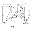
Figure 1 is a schematic diagram of a system for converting fuel material according to the invention, -
Figure 2 is a schematic view of a part of the system according to a first embodiment, and -
Figure 3 a schematic view of a part of the system according to a second embodiment. - As illustrated in
figure 1 , asystem 1 for converting fuel material according to the invention, which is intended to produce electricity and/or steam, comprises afuel reactor 2, anair reactor 3 and acarbon separator 4. - A solid fuel material coming from a
fuel silo 5 and a metal oxide coming from anoxide silo 6 enter thefuel reactor 2. The solid fuel material is preferably coal. The metal oxide can be based on iron, nickel, alumina or a mixture thereof. - The
fuel reactor 2 is fluidized by steam and/or recycled flue gas and/or carbon dioxide. A first separation device, preferably a lowefficiency separation cyclone 7, is fed with combustion gases, ash, fuel particles and oxide particles coming from thefuel reactor 2. The combustion gases comprise mainly CO2 and steam. - The efficiency of a separation device is the ratio of the quantity of particles collected by the device to the quantity of solids at the inlet of the device.
- The upper stream of the solids of the low
efficiency separation cyclone 7 is circulated into a high separation device, preferably a highefficiency separation cyclone 8. Thus, the solids comprising mainly fine carbon particles are separated from the fly ash and are re-introduced in thefuel reactor 2 via aseal pot 14. - The solids leaving the
low efficiency cyclone 7 enter aseal pot 9 from which a first portion is routed into thefuel reactor 2 and from which a second portion is routed into thecarbon separator 4. Theseal pot 9 can be fluidized by steam and/or recycled flue gas. - The
carbon separator 4 separates out the fine and light particles, such as the carbon-containing residue, which are sent to thefuel reactor 2, from the denser and larger oxide particles and ash which are sent to theair reactor 3. According to the invention, thecarbon separator 4 is connected to anash separator 10 that includes aspecific vent 10a to allow the ash to escape. The average particle diameter of the fuel material entering thefuel reactor 2 is preferably less than the average particle diameter of the oxide material. More preferably, the average particle diameter of the fuel material is controlled to be at least twice smaller than the average particle diameter of the oxide material. The average particle diameter of the fuel material can be equal to about 50 µm. It can be comprised between 50 and 60 µm. - In this case, the density of the oxide particles is higher than the density of the fuel particles, the density of the ash being comprised between the density of the fuel particles and the density of the oxide particles.
- The oxide particles coming from the carbon and
ash separator air reactor 3. The oxides and the depleted air leaving theair reactor 3 enter aseparation device 11, typically a cyclone separator, in which the oxide particles are separated from the gases comprising N2 an O2. - The solid oxide particles extracted from the bottom of the
cyclone 11 enter aseal pot 12 from which a first portion is transferred to the bottom of theair reactor 3 and from which a second portion is routed to the bottom of thefuel reactor 2. Theseal pot 12 can be fluidized with air. - A detailed view of the association of the
carbon separator 4 and theash separator 10 is shown infigures 2 and 3. Figures 2 and 3 schematically illustrate two embodiments of an assembly of a carbon separator and an ash separator used in the system for converting fuel material according to the invention. - The
carbon separator 4 comprises aninlet 4a through which the fuel particles FP, the oxide particles OP and the ash A enter thecarbon separator 4. The oxide particles OP are oxide particles that have been at least partially reduced in the fuel reactor. Thecarbon separator 4 is fluidized by fluidization means F. The fluidization means F can be steam and/or recycled flue gas and/or CO2 inlets placed at the bottom of thecarbon separator 4. - The fine and light fuel particles FP having a density of about 1.2 are directed toward the fuel reactor via
outlets 4b of thecarbon separator 4 while the denser and larger oxide particles OP and ash A are routed towards theash separator 10. - The
ash separator 10 is fluidized by fluidization means F. The fluidization means F can be steam and/or recycled flue gas and/or CO2 inlets placed at the bottom of thecarbon separator 4. The light ash A flows out thevent 10a towards a gas treatment system while the denser oxide particles OP passe through anoutlet 10b of theash separator 10 towards the air reactor. - The fluidizing velocity of the
carbon separator 4 and of theash separator 10 can be controlled in order to control the ash concentration in the system. The fluidizing velocity can be based on the respective density of ash A and oxide particles OP (about 2.5 and 4.5 respectively). Thus, theash separator 10 can be fluidized at a velocity comprised between 0.3 and 0.8 m/s and thecarbon separator 4 can be fluidized at a velocity comprised between 0.1 and 0.6 m/s. - According to a first embodiment, as shown in
figure 2 , thecarbon separator 4 and theash separator 10 are adjacent via acommon side wall 13. Thecarbon separator 4 and theash separator 10 are connected by anopening 4c of theside wall 13. - According to a second embodiment, as shown in
figure 3 , thecarbon separator 4 and theash separator 10 are connected by apipe 4c. Moreover, theash separator 10 can be placed below thecarbon separator 4 in order to facilitate the passage of the oxide particles OP and the ash A from thecarbon separator 4 to theash separator 10.
Claims (7)
- A system (1) for converting fuel material comprising :- a first reactor (2) in which a fuel material reacts with an oxide material for producing reaction products including fuel particles, ash and oxide particles,- a second reactor (3) for oxidizing the oxide particles produced in the first reactor (2),- a carbon separator (4) that receives fuel particles, ash and oxide particles produced in the first reactor (2) and suitable for separating the oxide particles and ash from the fuel particles, the carbon separator (4) comprising an outlet path (4c) for the oxide particles and ash exhaust,characterized in that said outlet path (4c) of the carbon separator (4) is connected to an ash separator (10) for separating the ash from the oxide particles.
- A system (1) according to claim 1, characterized in that both of the carbon separator (4) and the ash separator (10) are fluidized and in that the system (1) comprises means for controlling the fluidization velocity of each separator (4,10).
- A system (1) according to claim 2, characterized in that the means for controlling the fluidization velocity of each separator (4,10) are able to control these fluidization velocities so that the fluidization velocity of the ash separator (10) is higher than the fluidization velocity of the carbon separator (4).
- A system (1) according to any one of claims 1 to 3, characterized in that the carbon separator (4) and the ash separator (10) are adjacent separators (4,10) via a common side wall (13).
- A system (1) according to any one of claims 1 to 3, characterized in that the carbon separator (4) and the ash separator (10) are connected by a pipe (4c).
- A system (1) according to claim 5, characterized in that the ash separator (10) is placed below the carbon separator (4).
- A system (1) according to any one of claims 1 to 6, characterized in that the fuel reactor (2) is connected to a low efficiency cyclone separator (7) comprising a lower outlet connected to the carbon separator (4) and an upper outlet connected to a high efficiency cyclone separator (8).
Priority Applications (9)
| Application Number | Priority Date | Filing Date | Title |
|---|---|---|---|
| ES09162600T ES2421210T3 (en) | 2009-06-12 | 2009-06-12 | Fuel material conversion system |
| EP09162600.2A EP2273192B1 (en) | 2009-06-12 | 2009-06-12 | System for converting fuel material |
| PL09162600T PL2273192T3 (en) | 2009-06-12 | 2009-06-12 | System for converting fuel material |
| PCT/EP2010/057300 WO2010142533A1 (en) | 2009-06-12 | 2010-05-27 | System for converting fuel material |
| US13/375,977 US8807054B2 (en) | 2009-06-12 | 2010-05-27 | System for converting fuel materials |
| CN201080026196.1A CN102460017B (en) | 2009-06-12 | 2010-05-27 | System for converting fuel material |
| AU2010257649A AU2010257649B2 (en) | 2009-06-12 | 2010-05-27 | System for converting fuel material |
| CA2763964A CA2763964C (en) | 2009-06-12 | 2010-05-27 | System for converting fuel material |
| JP2012514413A JP5496327B2 (en) | 2009-06-12 | 2010-05-27 | Fuel material conversion system |
Applications Claiming Priority (1)
| Application Number | Priority Date | Filing Date | Title |
|---|---|---|---|
| EP09162600.2A EP2273192B1 (en) | 2009-06-12 | 2009-06-12 | System for converting fuel material |
Publications (2)
| Publication Number | Publication Date |
|---|---|
| EP2273192A1 EP2273192A1 (en) | 2011-01-12 |
| EP2273192B1 true EP2273192B1 (en) | 2013-05-22 |
Family
ID=41395862
Family Applications (1)
| Application Number | Title | Priority Date | Filing Date |
|---|---|---|---|
| EP09162600.2A Active EP2273192B1 (en) | 2009-06-12 | 2009-06-12 | System for converting fuel material |
Country Status (9)
| Country | Link |
|---|---|
| US (1) | US8807054B2 (en) |
| EP (1) | EP2273192B1 (en) |
| JP (1) | JP5496327B2 (en) |
| CN (1) | CN102460017B (en) |
| AU (1) | AU2010257649B2 (en) |
| CA (1) | CA2763964C (en) |
| ES (1) | ES2421210T3 (en) |
| PL (1) | PL2273192T3 (en) |
| WO (1) | WO2010142533A1 (en) |
Families Citing this family (18)
| Publication number | Priority date | Publication date | Assignee | Title |
|---|---|---|---|---|
| FR2948177B1 (en) * | 2009-07-16 | 2011-08-05 | Inst Francais Du Petrole | CHEMICAL LOOP COMBUSTION PROCESS WITH INDEPENDENT CONTROL OF SOLIDS CIRCULATION |
| US9101900B2 (en) | 2011-07-27 | 2015-08-11 | Res Usa, Llc | Gasification system and method |
| FR2980258B1 (en) | 2011-09-20 | 2017-12-29 | Ifp Energies Now | CHEMICAL LOOP COMBUSTION PROCESS WITH REMOVAL OF ASHES AND FINES IN THE REDUCTION AREA AND INSTALLATION USING SUCH A METHOD |
| EP2771434A4 (en) * | 2011-10-26 | 2016-01-13 | Res Usa Llc | Seal pot design |
| FR2983489B1 (en) | 2011-12-02 | 2013-11-15 | IFP Energies Nouvelles | CHEMICAL LOOP COMBUSTION PROCESS WITH DILUTE PHASE REMOVAL OF ASHES AND FINESS IN OXIDATION AREA AND INSTALLATION USING SUCH A METHOD |
| FR2983488B1 (en) * | 2011-12-02 | 2013-11-15 | IFP Energies Nouvelles | CHEMICAL LOOP COMBUSTION PROCESS WITH REMOVAL OF ASHES AND FINISHES EXIT FROM OXIDATION AREA AND INSTALLATION USING SUCH A METHOD |
| CN102937290B (en) * | 2012-11-21 | 2015-08-26 | 中国东方电气集团有限公司 | The double-fluidized-bed system preventing boiler from staiing of a kind of external bed |
| WO2014085243A1 (en) * | 2012-11-30 | 2014-06-05 | Saudi Arabian Oil Company | Staged chemical looping process with integrated oxygen generation |
| CN104232120B (en) * | 2013-06-10 | 2017-03-29 | 何巨堂 | It is a kind of to drop grey method using series fluidized bed powdery carbon material |
| CN103486576A (en) * | 2013-09-25 | 2014-01-01 | 上海锅炉厂有限公司 | Chemical chain combustion device and method for three-reactor structure |
| FR3022611B1 (en) * | 2014-06-19 | 2016-07-08 | Ifp Energies Now | METHOD AND INSTALLATION OF COMBUSTION BY OXYDO-REDUCTION IN CHEMICAL LOOP WITH CHECKING HEAT EXCHANGES |
| CN104119960B (en) * | 2014-07-31 | 2016-07-20 | 新奥科技发展有限公司 | A kind of flying dust separation method |
| JP2016080240A (en) * | 2014-10-15 | 2016-05-16 | 株式会社Ihi | Chemical loop combustion device |
| US9765961B2 (en) | 2015-03-17 | 2017-09-19 | Saudi Arabian Oil Company | Chemical looping combustion process with multiple fuel reaction zones and gravity feed of oxidized particles |
| JP6455290B2 (en) * | 2015-04-08 | 2019-01-23 | 株式会社Ihi | Chemical loop combustion apparatus and chemical loop combustion method |
| CN106398768B (en) * | 2016-11-04 | 2021-10-08 | 河南农业大学 | Device and method for preparing synthesis gas by chemical looping combustion |
| US10343112B2 (en) | 2016-12-27 | 2019-07-09 | General Electric Company | System and method for sulfur recapture in a chemical looping system |
| FR3084138B1 (en) * | 2018-07-23 | 2020-07-24 | Ifp Energies Now | CLC INSTALLATION INCLUDING A SOLID / SOLID SEPARATOR WITH MEANS FOR DISPERSING A GAS-SOLID MIXTURE |
Family Cites Families (13)
| Publication number | Priority date | Publication date | Assignee | Title |
|---|---|---|---|---|
| FR2563118B1 (en) * | 1984-04-20 | 1987-04-30 | Creusot Loire | PROCESS AND PLANT FOR TREATING FLUIDIZED BED MATERIAL |
| FI873735A0 (en) * | 1987-08-28 | 1987-08-28 | Ahlstroem Oy | FOERFARANDE OCH ANORDNING FOER FOERGASNING AV FAST KOLHALTIGT MATERIAL. |
| FI85909C (en) * | 1989-02-22 | 1992-06-10 | Ahlstroem Oy | ANORDNING FOER FOERGASNING ELLER FOERBRAENNING AV FAST KOLHALTIGT MATERIAL. |
| JPH0464812A (en) * | 1990-07-04 | 1992-02-28 | Mitsubishi Heavy Ind Ltd | Disposing method for combustion ash of fluidized bed |
| JP3315719B2 (en) * | 1992-06-03 | 2002-08-19 | 東京電力株式会社 | Chemical loop combustion power plant system |
| JP2002102835A (en) | 2000-09-28 | 2002-04-09 | Nkk Corp | Method and apparatus for treating dust produced from waste incineration |
| US6494153B1 (en) * | 2001-07-31 | 2002-12-17 | General Electric Co. | Unmixed combustion of coal with sulfur recycle |
| JP2003074814A (en) * | 2001-08-31 | 2003-03-12 | Mitsui Eng & Shipbuild Co Ltd | Waste treatment equipment |
| FR2850156B1 (en) * | 2003-01-16 | 2005-12-30 | Alstom Switzerland Ltd | COMBUSTION INSTALLATION WITH CO2 RECOVERY |
| FR2883773B1 (en) * | 2005-04-01 | 2007-05-11 | Alstom Sa | COMBUSTION DEVICE PRODUCING HYDROGEN WITH REUSE OF CO2 CAPTURE |
| WO2007014984A1 (en) * | 2005-08-01 | 2007-02-08 | Alstom Technology Ltd | Modular fluidised bed reactor |
| FR2895413B1 (en) | 2005-12-27 | 2011-07-29 | Alstom Technology Ltd | PETROLEUM HYDROCARBON CONVERSION INSTALLATION WITH INTEGRATED COMBUSTION FACILITY COMPRISING CAPTURE OF CARBON DIOXIDE |
| US20090020405A1 (en) * | 2007-07-20 | 2009-01-22 | Foster Wheeler Energy Corporation | Method of and a plant for combusting carbonaceous fuel by using a solid oxygen carrier |
-
2009
- 2009-06-12 EP EP09162600.2A patent/EP2273192B1/en active Active
- 2009-06-12 ES ES09162600T patent/ES2421210T3/en active Active
- 2009-06-12 PL PL09162600T patent/PL2273192T3/en unknown
-
2010
- 2010-05-27 CN CN201080026196.1A patent/CN102460017B/en active Active
- 2010-05-27 WO PCT/EP2010/057300 patent/WO2010142533A1/en active Application Filing
- 2010-05-27 AU AU2010257649A patent/AU2010257649B2/en not_active Ceased
- 2010-05-27 CA CA2763964A patent/CA2763964C/en not_active Expired - Fee Related
- 2010-05-27 US US13/375,977 patent/US8807054B2/en not_active Expired - Fee Related
- 2010-05-27 JP JP2012514413A patent/JP5496327B2/en active Active
Also Published As
| Publication number | Publication date |
|---|---|
| US8807054B2 (en) | 2014-08-19 |
| EP2273192A1 (en) | 2011-01-12 |
| ES2421210T3 (en) | 2013-08-29 |
| WO2010142533A1 (en) | 2010-12-16 |
| CN102460017B (en) | 2014-12-24 |
| CA2763964C (en) | 2013-09-10 |
| CA2763964A1 (en) | 2010-12-16 |
| JP2012529614A (en) | 2012-11-22 |
| US20120167808A1 (en) | 2012-07-05 |
| PL2273192T3 (en) | 2013-09-30 |
| AU2010257649A1 (en) | 2012-01-19 |
| JP5496327B2 (en) | 2014-05-21 |
| AU2010257649B2 (en) | 2015-11-12 |
| CN102460017A (en) | 2012-05-16 |
Similar Documents
| Publication | Publication Date | Title |
|---|---|---|
| EP2273192B1 (en) | System for converting fuel material | |
| CA2721101C (en) | Process for using a facility for combusting carbonaceous materials | |
| US9616403B2 (en) | Systems and methods for converting carbonaceous fuels | |
| KR100996373B1 (en) | Oil-derived hydrocarbon converter having an integrated combustion installation comprising carbon dioxide capture | |
| EP1798276B1 (en) | Methods and systems for partial moderator bypass | |
| US8499702B2 (en) | Char-handling processes in a pyrolysis system | |
| AU2011260164A1 (en) | Particle separation device for chemical looping combustion loop | |
| EP2107302B1 (en) | Process for using a facility for combusting carbonaceous materials and relating facility | |
| US7987993B2 (en) | Solid separator especially for a combustion facility | |
| EP0294024B1 (en) | Process for removing nitrous oxides from a gas | |
| US11913640B2 (en) | Device and method for chemical looping combustion, having a particle separator provided with an inclined intake duct | |
| CN108946659B (en) | System and method for preparing hydrogen through petroleum coke gasification | |
| CN117531444A (en) | Chemical looping combustion/gasification coupling hydrogen production system and hydrogen production method |
Legal Events
| Date | Code | Title | Description |
|---|---|---|---|
| PUAI | Public reference made under article 153(3) epc to a published international application that has entered the european phase |
Free format text: ORIGINAL CODE: 0009012 |
|
| AK | Designated contracting states |
Kind code of ref document: A1 Designated state(s): AT BE BG CH CY CZ DE DK EE ES FI FR GB GR HR HU IE IS IT LI LT LU LV MC MK MT NL NO PL PT RO SE SI SK TR |
|
| AX | Request for extension of the european patent |
Extension state: AL BA RS |
|
| 17P | Request for examination filed |
Effective date: 20110615 |
|
| GRAP | Despatch of communication of intention to grant a patent |
Free format text: ORIGINAL CODE: EPIDOSNIGR1 |
|
| GRAS | Grant fee paid |
Free format text: ORIGINAL CODE: EPIDOSNIGR3 |
|
| GRAA | (expected) grant |
Free format text: ORIGINAL CODE: 0009210 |
|
| AK | Designated contracting states |
Kind code of ref document: B1 Designated state(s): AT BE BG CH CY CZ DE DK EE ES FI FR GB GR HR HU IE IS IT LI LT LU LV MC MK MT NL NO PL PT RO SE SI SK TR |
|
| REG | Reference to a national code |
Ref country code: GB Ref legal event code: FG4D |
|
| REG | Reference to a national code |
Ref country code: CH Ref legal event code: EP |
|
| REG | Reference to a national code |
Ref country code: AT Ref legal event code: REF Ref document number: 613424 Country of ref document: AT Kind code of ref document: T Effective date: 20130615 |
|
| REG | Reference to a national code |
Ref country code: IE Ref legal event code: FG4D |
|
| REG | Reference to a national code |
Ref country code: DE Ref legal event code: R096 Ref document number: 602009015827 Country of ref document: DE Effective date: 20130718 |
|
| REG | Reference to a national code |
Ref country code: ES Ref legal event code: FG2A Ref document number: 2421210 Country of ref document: ES Kind code of ref document: T3 Effective date: 20130829 |
|
| REG | Reference to a national code |
Ref country code: PL Ref legal event code: T3 |
|
| REG | Reference to a national code |
Ref country code: AT Ref legal event code: MK05 Ref document number: 613424 Country of ref document: AT Kind code of ref document: T Effective date: 20130522 |
|
| REG | Reference to a national code |
Ref country code: LT Ref legal event code: MG4D |
|
| PG25 | Lapsed in a contracting state [announced via postgrant information from national office to epo] |
Ref country code: SI Free format text: LAPSE BECAUSE OF FAILURE TO SUBMIT A TRANSLATION OF THE DESCRIPTION OR TO PAY THE FEE WITHIN THE PRESCRIBED TIME-LIMIT Effective date: 20130522 Ref country code: SE Free format text: LAPSE BECAUSE OF FAILURE TO SUBMIT A TRANSLATION OF THE DESCRIPTION OR TO PAY THE FEE WITHIN THE PRESCRIBED TIME-LIMIT Effective date: 20130522 Ref country code: LT Free format text: LAPSE BECAUSE OF FAILURE TO SUBMIT A TRANSLATION OF THE DESCRIPTION OR TO PAY THE FEE WITHIN THE PRESCRIBED TIME-LIMIT Effective date: 20130522 Ref country code: NO Free format text: LAPSE BECAUSE OF FAILURE TO SUBMIT A TRANSLATION OF THE DESCRIPTION OR TO PAY THE FEE WITHIN THE PRESCRIBED TIME-LIMIT Effective date: 20130822 Ref country code: PT Free format text: LAPSE BECAUSE OF FAILURE TO SUBMIT A TRANSLATION OF THE DESCRIPTION OR TO PAY THE FEE WITHIN THE PRESCRIBED TIME-LIMIT Effective date: 20130923 Ref country code: IS Free format text: LAPSE BECAUSE OF FAILURE TO SUBMIT A TRANSLATION OF THE DESCRIPTION OR TO PAY THE FEE WITHIN THE PRESCRIBED TIME-LIMIT Effective date: 20130922 Ref country code: AT Free format text: LAPSE BECAUSE OF FAILURE TO SUBMIT A TRANSLATION OF THE DESCRIPTION OR TO PAY THE FEE WITHIN THE PRESCRIBED TIME-LIMIT Effective date: 20130522 Ref country code: GR Free format text: LAPSE BECAUSE OF FAILURE TO SUBMIT A TRANSLATION OF THE DESCRIPTION OR TO PAY THE FEE WITHIN THE PRESCRIBED TIME-LIMIT Effective date: 20130823 |
|
| REG | Reference to a national code |
Ref country code: NL Ref legal event code: VDEP Effective date: 20130522 |
|
| PG25 | Lapsed in a contracting state [announced via postgrant information from national office to epo] |
Ref country code: HR Free format text: LAPSE BECAUSE OF FAILURE TO SUBMIT A TRANSLATION OF THE DESCRIPTION OR TO PAY THE FEE WITHIN THE PRESCRIBED TIME-LIMIT Effective date: 20130522 Ref country code: BG Free format text: LAPSE BECAUSE OF FAILURE TO SUBMIT A TRANSLATION OF THE DESCRIPTION OR TO PAY THE FEE WITHIN THE PRESCRIBED TIME-LIMIT Effective date: 20130822 |
|
| PG25 | Lapsed in a contracting state [announced via postgrant information from national office to epo] |
Ref country code: LV Free format text: LAPSE BECAUSE OF FAILURE TO SUBMIT A TRANSLATION OF THE DESCRIPTION OR TO PAY THE FEE WITHIN THE PRESCRIBED TIME-LIMIT Effective date: 20130522 |
|
| PG25 | Lapsed in a contracting state [announced via postgrant information from national office to epo] |
Ref country code: CZ Free format text: LAPSE BECAUSE OF FAILURE TO SUBMIT A TRANSLATION OF THE DESCRIPTION OR TO PAY THE FEE WITHIN THE PRESCRIBED TIME-LIMIT Effective date: 20130522 Ref country code: BE Free format text: LAPSE BECAUSE OF FAILURE TO SUBMIT A TRANSLATION OF THE DESCRIPTION OR TO PAY THE FEE WITHIN THE PRESCRIBED TIME-LIMIT Effective date: 20130522 Ref country code: DK Free format text: LAPSE BECAUSE OF FAILURE TO SUBMIT A TRANSLATION OF THE DESCRIPTION OR TO PAY THE FEE WITHIN THE PRESCRIBED TIME-LIMIT Effective date: 20130522 Ref country code: SK Free format text: LAPSE BECAUSE OF FAILURE TO SUBMIT A TRANSLATION OF THE DESCRIPTION OR TO PAY THE FEE WITHIN THE PRESCRIBED TIME-LIMIT Effective date: 20130522 Ref country code: EE Free format text: LAPSE BECAUSE OF FAILURE TO SUBMIT A TRANSLATION OF THE DESCRIPTION OR TO PAY THE FEE WITHIN THE PRESCRIBED TIME-LIMIT Effective date: 20130522 |
|
| REG | Reference to a national code |
Ref country code: CH Ref legal event code: PL |
|
| PG25 | Lapsed in a contracting state [announced via postgrant information from national office to epo] |
Ref country code: NL Free format text: LAPSE BECAUSE OF FAILURE TO SUBMIT A TRANSLATION OF THE DESCRIPTION OR TO PAY THE FEE WITHIN THE PRESCRIBED TIME-LIMIT Effective date: 20130522 Ref country code: IT Free format text: LAPSE BECAUSE OF FAILURE TO SUBMIT A TRANSLATION OF THE DESCRIPTION OR TO PAY THE FEE WITHIN THE PRESCRIBED TIME-LIMIT Effective date: 20130522 Ref country code: MC Free format text: LAPSE BECAUSE OF FAILURE TO SUBMIT A TRANSLATION OF THE DESCRIPTION OR TO PAY THE FEE WITHIN THE PRESCRIBED TIME-LIMIT Effective date: 20130522 Ref country code: RO Free format text: LAPSE BECAUSE OF FAILURE TO SUBMIT A TRANSLATION OF THE DESCRIPTION OR TO PAY THE FEE WITHIN THE PRESCRIBED TIME-LIMIT Effective date: 20130522 |
|
| REG | Reference to a national code |
Ref country code: IE Ref legal event code: MM4A |
|
| PLBE | No opposition filed within time limit |
Free format text: ORIGINAL CODE: 0009261 |
|
| STAA | Information on the status of an ep patent application or granted ep patent |
Free format text: STATUS: NO OPPOSITION FILED WITHIN TIME LIMIT |
|
| GBPC | Gb: european patent ceased through non-payment of renewal fee |
Effective date: 20130822 |
|
| 26N | No opposition filed |
Effective date: 20140225 |
|
| PG25 | Lapsed in a contracting state [announced via postgrant information from national office to epo] |
Ref country code: LI Free format text: LAPSE BECAUSE OF NON-PAYMENT OF DUE FEES Effective date: 20130630 Ref country code: IE Free format text: LAPSE BECAUSE OF NON-PAYMENT OF DUE FEES Effective date: 20130612 Ref country code: CH Free format text: LAPSE BECAUSE OF NON-PAYMENT OF DUE FEES Effective date: 20130630 |
|
| REG | Reference to a national code |
Ref country code: DE Ref legal event code: R097 Ref document number: 602009015827 Country of ref document: DE Effective date: 20140225 |
|
| PG25 | Lapsed in a contracting state [announced via postgrant information from national office to epo] |
Ref country code: GB Free format text: LAPSE BECAUSE OF NON-PAYMENT OF DUE FEES Effective date: 20130822 |
|
| PG25 | Lapsed in a contracting state [announced via postgrant information from national office to epo] |
Ref country code: MT Free format text: LAPSE BECAUSE OF FAILURE TO SUBMIT A TRANSLATION OF THE DESCRIPTION OR TO PAY THE FEE WITHIN THE PRESCRIBED TIME-LIMIT Effective date: 20130522 |
|
| REG | Reference to a national code |
Ref country code: FR Ref legal event code: PLFP Year of fee payment: 7 |
|
| PG25 | Lapsed in a contracting state [announced via postgrant information from national office to epo] |
Ref country code: TR Free format text: LAPSE BECAUSE OF FAILURE TO SUBMIT A TRANSLATION OF THE DESCRIPTION OR TO PAY THE FEE WITHIN THE PRESCRIBED TIME-LIMIT Effective date: 20130522 Ref country code: CY Free format text: LAPSE BECAUSE OF FAILURE TO SUBMIT A TRANSLATION OF THE DESCRIPTION OR TO PAY THE FEE WITHIN THE PRESCRIBED TIME-LIMIT Effective date: 20130522 |
|
| PG25 | Lapsed in a contracting state [announced via postgrant information from national office to epo] |
Ref country code: LU Free format text: LAPSE BECAUSE OF NON-PAYMENT OF DUE FEES Effective date: 20130612 Ref country code: MK Free format text: LAPSE BECAUSE OF FAILURE TO SUBMIT A TRANSLATION OF THE DESCRIPTION OR TO PAY THE FEE WITHIN THE PRESCRIBED TIME-LIMIT Effective date: 20130522 Ref country code: HU Free format text: LAPSE BECAUSE OF FAILURE TO SUBMIT A TRANSLATION OF THE DESCRIPTION OR TO PAY THE FEE WITHIN THE PRESCRIBED TIME-LIMIT; INVALID AB INITIO Effective date: 20090612 |
|
| REG | Reference to a national code |
Ref country code: FR Ref legal event code: PLFP Year of fee payment: 8 |
|
| REG | Reference to a national code |
Ref country code: DE Ref legal event code: R082 Ref document number: 602009015827 Country of ref document: DE Representative=s name: RUEGER | ABEL PATENT- UND RECHTSANWAELTE, DE Ref country code: DE Ref legal event code: R082 Ref document number: 602009015827 Country of ref document: DE Representative=s name: RUEGER ABEL PATENTANWAELTE PARTGMBB, DE Ref country code: DE Ref legal event code: R082 Ref document number: 602009015827 Country of ref document: DE Representative=s name: RUEGER, BARTHELT & ABEL, DE Ref country code: DE Ref legal event code: R081 Ref document number: 602009015827 Country of ref document: DE Owner name: GENERAL ELECTRIC TECHNOLOGY GMBH, CH Free format text: FORMER OWNER: ALSTOM TECHNOLOGY LTD., BADEN, CH Ref country code: DE Ref legal event code: R082 Ref document number: 602009015827 Country of ref document: DE Representative=s name: RUEGER ABEL PATENT- UND RECHTSANWAELTE, DE |
|
| REG | Reference to a national code |
Ref country code: ES Ref legal event code: PC2A Owner name: GENERAL ELECTRIC TECHNOLOGY GMBH Effective date: 20161115 |
|
| REG | Reference to a national code |
Ref country code: FR Ref legal event code: CD Owner name: ALSTOM TECHNOLOGY LTD, CH Effective date: 20161124 |
|
| REG | Reference to a national code |
Ref country code: FR Ref legal event code: PLFP Year of fee payment: 9 |
|
| PGFP | Annual fee paid to national office [announced via postgrant information from national office to epo] |
Ref country code: FR Payment date: 20170627 Year of fee payment: 9 |
|
| PGFP | Annual fee paid to national office [announced via postgrant information from national office to epo] |
Ref country code: ES Payment date: 20170705 Year of fee payment: 9 Ref country code: DE Payment date: 20170628 Year of fee payment: 9 |
|
| REG | Reference to a national code |
Ref country code: DE Ref legal event code: R119 Ref document number: 602009015827 Country of ref document: DE |
|
| PG25 | Lapsed in a contracting state [announced via postgrant information from national office to epo] |
Ref country code: DE Free format text: LAPSE BECAUSE OF NON-PAYMENT OF DUE FEES Effective date: 20190101 Ref country code: FR Free format text: LAPSE BECAUSE OF NON-PAYMENT OF DUE FEES Effective date: 20180630 |
|
| REG | Reference to a national code |
Ref country code: ES Ref legal event code: FD2A Effective date: 20190916 |
|
| PG25 | Lapsed in a contracting state [announced via postgrant information from national office to epo] |
Ref country code: ES Free format text: LAPSE BECAUSE OF NON-PAYMENT OF DUE FEES Effective date: 20180613 |
|
| PGFP | Annual fee paid to national office [announced via postgrant information from national office to epo] |
Ref country code: PL Payment date: 20210520 Year of fee payment: 13 |
|
| PG25 | Lapsed in a contracting state [announced via postgrant information from national office to epo] |
Ref country code: PL Free format text: LAPSE BECAUSE OF NON-PAYMENT OF DUE FEES Effective date: 20220612 |
|
| PGFP | Annual fee paid to national office [announced via postgrant information from national office to epo] |
Ref country code: FI Payment date: 20230523 Year of fee payment: 15 |