EP2273155A1 - Transmission for a self-propelled tiller and tiller with a respective transmission - Google Patents
Transmission for a self-propelled tiller and tiller with a respective transmission Download PDFInfo
- Publication number
- EP2273155A1 EP2273155A1 EP10168376A EP10168376A EP2273155A1 EP 2273155 A1 EP2273155 A1 EP 2273155A1 EP 10168376 A EP10168376 A EP 10168376A EP 10168376 A EP10168376 A EP 10168376A EP 2273155 A1 EP2273155 A1 EP 2273155A1
- Authority
- EP
- European Patent Office
- Prior art keywords
- pulley
- input shaft
- shell
- drive
- gearbox
- Prior art date
- Legal status (The legal status is an assumption and is not a legal conclusion. Google has not performed a legal analysis and makes no representation as to the accuracy of the status listed.)
- Granted
Links
- 230000005540 biological transmission Effects 0.000 title claims description 42
- 230000002093 peripheral effect Effects 0.000 claims description 12
- 238000004140 cleaning Methods 0.000 claims description 8
- 238000005192 partition Methods 0.000 claims description 6
- 230000001680 brushing effect Effects 0.000 claims description 5
- 230000000295 complement effect Effects 0.000 claims description 3
- 239000004033 plastic Substances 0.000 claims description 2
- 229920003023 plastic Polymers 0.000 claims description 2
- 235000021183 entrée Nutrition 0.000 description 15
- 125000006850 spacer group Chemical group 0.000 description 6
- 238000004519 manufacturing process Methods 0.000 description 5
- 230000008859 change Effects 0.000 description 4
- 230000004048 modification Effects 0.000 description 4
- 238000012986 modification Methods 0.000 description 4
- 229920002943 EPDM rubber Polymers 0.000 description 3
- 238000012423 maintenance Methods 0.000 description 3
- 230000009471 action Effects 0.000 description 2
- XAGFODPZIPBFFR-UHFFFAOYSA-N aluminium Chemical compound [Al] XAGFODPZIPBFFR-UHFFFAOYSA-N 0.000 description 2
- 229910052782 aluminium Inorganic materials 0.000 description 2
- 230000000903 blocking effect Effects 0.000 description 2
- 230000003749 cleanliness Effects 0.000 description 2
- 239000011248 coating agent Substances 0.000 description 2
- 238000000576 coating method Methods 0.000 description 2
- 229920001971 elastomer Polymers 0.000 description 2
- 238000009966 trimming Methods 0.000 description 2
- 239000004698 Polyethylene Substances 0.000 description 1
- 230000002457 bidirectional effect Effects 0.000 description 1
- 239000004020 conductor Substances 0.000 description 1
- 230000007423 decrease Effects 0.000 description 1
- 230000002950 deficient Effects 0.000 description 1
- 238000006073 displacement reaction Methods 0.000 description 1
- 239000000463 material Substances 0.000 description 1
- 230000007246 mechanism Effects 0.000 description 1
- 239000002991 molded plastic Substances 0.000 description 1
- 210000000056 organ Anatomy 0.000 description 1
- -1 polyethylene Polymers 0.000 description 1
- 229920000573 polyethylene Polymers 0.000 description 1
- 230000008439 repair process Effects 0.000 description 1
- 239000011435 rock Substances 0.000 description 1
- 238000001175 rotational moulding Methods 0.000 description 1
- 230000002269 spontaneous effect Effects 0.000 description 1
- 230000007704 transition Effects 0.000 description 1
- 239000011800 void material Substances 0.000 description 1
Images


Classifications
-
- A—HUMAN NECESSITIES
- A01—AGRICULTURE; FORESTRY; ANIMAL HUSBANDRY; HUNTING; TRAPPING; FISHING
- A01D—HARVESTING; MOWING
- A01D69/00—Driving mechanisms or parts thereof for harvesters or mowers
- A01D69/06—Gearings
-
- A—HUMAN NECESSITIES
- A01—AGRICULTURE; FORESTRY; ANIMAL HUSBANDRY; HUNTING; TRAPPING; FISHING
- A01B—SOIL WORKING IN AGRICULTURE OR FORESTRY; PARTS, DETAILS, OR ACCESSORIES OF AGRICULTURAL MACHINES OR IMPLEMENTS, IN GENERAL
- A01B33/00—Tilling implements with rotary driven tools, e.g. in combination with fertiliser distributors or seeders, with grubbing chains, with sloping axles, with driven discs
- A01B33/08—Tools; Details, e.g. adaptations of transmissions or gearings
-
- F—MECHANICAL ENGINEERING; LIGHTING; HEATING; WEAPONS; BLASTING
- F16—ENGINEERING ELEMENTS AND UNITS; GENERAL MEASURES FOR PRODUCING AND MAINTAINING EFFECTIVE FUNCTIONING OF MACHINES OR INSTALLATIONS; THERMAL INSULATION IN GENERAL
- F16H—GEARING
- F16H15/00—Gearings for conveying rotary motion with variable gear ratio, or for reversing rotary motion, by friction between rotary members
- F16H15/02—Gearings for conveying rotary motion with variable gear ratio, or for reversing rotary motion, by friction between rotary members without members having orbital motion
- F16H15/04—Gearings providing a continuous range of gear ratios
- F16H15/06—Gearings providing a continuous range of gear ratios in which a member A of uniform effective diameter mounted on a shaft may co-operate with different parts of a member B
- F16H15/08—Gearings providing a continuous range of gear ratios in which a member A of uniform effective diameter mounted on a shaft may co-operate with different parts of a member B in which the member B is a disc with a flat or approximately flat friction surface
- F16H15/10—Gearings providing a continuous range of gear ratios in which a member A of uniform effective diameter mounted on a shaft may co-operate with different parts of a member B in which the member B is a disc with a flat or approximately flat friction surface in which the axes of the two members cross or intersect
Definitions
- the invention relates to transmissions for brushcutting equipment, in particular transmissions for equipment with walking conductors.
- the invention also relates to self-propelled brushing equipment equipped with gearboxes.
- Self-cleaning brushing equipment comprises a motor, means for driving the equipment on a brushcutter surface, brushcutter cutting tools and a gearbox arranged between the motor and the drive means of the equipment on the area to be brushed.
- brushcutter garden equipment There are a large number of brushcutter garden equipment, the choice of which depends in particular on the area to be brushed and the type of plants to be brushed.
- the most advanced equipment comprises gearboxes comprising several speeds to adapt the pace of the equipment to the surface to be brushed.
- Some equipment also has a reverse for easy maneuvers, for example in the vicinity of an obstacle, such as a fence, a shaft, etc., and a disengagement mechanism to facilitate the change of pace and the transition from the forward to the reverse.
- a reverse for easy maneuvers, for example in the vicinity of an obstacle, such as a fence, a shaft, etc.
- a disengagement mechanism to facilitate the change of pace and the transition from the forward to the reverse.
- Gearboxes of such garden equipment implement a large number of complex mechanical parts, which make them expensive boxes, heavy and bulky.
- each type of brushcutter garden equipment is provided, according to the features that are conferred to it-single speed, multiple speeds, reverse, brake, etc.- of a specific transmission box. So, to each new product range, the manufacturer must develop a new transmission box that meets the technical specifications of this product. The manufacture of molds, including can cases is a long operation, expensive and delicate. In addition, once the mold is made, the addition of any new functionality related to the transmission is impossible except to redo a mold.
- the invention aims to overcome at least some of the disadvantages of transmission boxes of the state of the art.
- the invention aims to provide, in at least one embodiment, a modular transmission box that can be configured to be used with different self-trimming equipment, regardless of their specifications.
- the invention also aims to provide, in at least one embodiment, a scalable gearbox that can receive new features to upgrade previous brushcutting equipment on which it is mounted.
- the invention also aims to provide, in at least one embodiment, an economical gearbox to manufacture.
- the invention also aims to provide, in at least one embodiment, a transmission box that allows easy maintenance.
- the invention also aims to provide, in at least one embodiment, a transmission box which disassembly and repair are easy.
- the invention also aims to provide, in at least one embodiment, a compact gearbox.
- the invention also aims to provide, in at least one embodiment, a transmission box which has a reduced number of parts.
- the invention also aims to provide, in at least one embodiment, a transmission box that secures the brush clearing equipment on which the box is mounted.
- a gearbox according to the invention thus has two half-shells defining a receiving housing of the input shaft having a shape and dimensions shaped and combined with the shape and dimensions of the input shaft equipped with either a forward disk and / or a reverse disk and / or a variable speed drive.
- a casing of a gearbox according to the invention can therefore receive a wide variety of transmission members.
- a transmission box according to the invention may comprise an input shaft equipped with a forward disc to equip the equipment on which the box is mounted with a forward function.
- a transmission box according to the invention may comprise an input shaft equipped with a forward disk and a variable speed drive for providing the equipment on which the gearbox is mounted with several speeds in the forward direction.
- the transmission box according to the invention may comprise an input shaft equipped with a reverse disk to provide the equipment on which the box is mounted a reverse.
- the housing is formed of half-shells defining a receiving housing of the input shaft, the latter being able to be equipped with a forward disk, a reverse disk or a speed variator.
- the receiving housing makes it possible to receive different configurations of the input shaft without, however, imposing a modification of the other members of the gearbox.
- the output shaft and the meshing means do not have to undergo any modification of structure, shape, or arrangement within the box, to allow a change of configuration of the d-tree. 'Entrance.
- the casing of a housing according to the invention being formed of two half-shells, it is particularly easy to access the inside of the box by dismounting the upper half-shell to change the configuration of the shaft input, or to replace a defective component. Maintenance of a box according to the invention is therefore easy.
- the receiving housing of the input shaft can also according to a variant of the invention act as reception housing of the output shaft, or even meshing means.
- a transmission box according to the invention is adapted to receive different configurations of the input shaft so as to adapt the functionality of the box to different brushcutting equipment without changing the other elements of the box.
- the output shaft is connected to said drive means of said equipment on said brushcutter surface.
- Such a gearbox is therefore arranged between the drive means and the drive means of the equipment on the brushcutter surface, such as the wheels of the equipment.
- the box comprises a forward drive disk and a reverse drive disk mounted on said input shaft, each drive disk being integral in rotation with said drive shaft. input and can be rotated through the pulley.
- This variant therefore corresponds to the configuration of the input shaft in which the shaft is equipped with a forward drive disc and a reverse drive disc.
- This arrangement forms a clutch that can move from an engaged position to a disengaged position.
- the pulley is rotated by means of motor means. These include for example an engine output gear having a peripheral groove in which is mounted a belt which connects the pinion to the pulley so that the rotation of the drive pinion causes the rotation of the pulley.
- This pulley when tilted into an engaged position, frictionally drives a drive disk of the input shaft. Friction takes place between the upper cheek of the pulley and the peripheral contour of the disc.
- Each drive disk being rotatably connected to the input shaft, the rotation of a drive disk causes the rotation of the input shaft. Therefore, in an engaged position, the input shaft is rotated and thus causes rotation of the output shaft connected to the input shaft by the meshing means.
- the output shaft in turn drives the drive means of the equipment on the brushcut surface, which allows the equipment to be moved on the brushcutter surface.
- This clutch is particularly suitable for garden equipment since it is economical to achieve, allows a passage from the disengaged position to a position in engagement simply and effectively by a relative tilting between the box housing and the pulley, and further allows easy maintenance of the clutch.
- the pivot connection is arranged between the forward drive disk and the reverse drive disk extending along a diametral axis of the pulley. Therefore, tilting of the pulley on a first side causes rotation of the forward drive disc in a first direction of rotation and tilting of the pulley on the opposite side causes rotation of the reverse drive disc. in a second direction of rotation, opposite the first direction of rotation, which drives the input shaft in one direction or the other depending on the tilting position of the pulley.
- the gearbox comprises a speed variator comprising a fixed crown of the driving disc in forward direction and a radial fork extending through an opening in said upper half-shell to be operable by an operator to move said drive disk forward along a portion of the input shaft.
- Such a variator can move the drive disk forward along the upper cheek of the pulley.
- the rotational speed of the disk decreases, while when the disk is moved to the center of the cheek of the pulley, the speed increases.
- moving the drive disk forward along a radial axis of the cheek of the pulley makes it possible to continuously vary the speed of the input shaft, which ensures a continuous variation of the speed on the brushcutter surface of the brushcutter.
- the gearbox comprises a speed variator comprising a ring integral with the drive disk in reverse and a radial fork extending through an opening in said upper half-shell so that it can be maneuver by an operator for moving said drive disc in reverse along a portion of the input shaft.
- the upper half-shell of a housing according to the invention advantageously comprises a zone for receiving and / or guiding a sheath carrying a control cable of the speed variator.
- This brake lever allows in the braked position to block the rotation of the input shaft by action on the drive disc in reverse by direct support on the drive disc.
- the drive disc in reverse is coated with a peripheral seal of rubber or EPDM (Ethylene Propylene Diene Monomer) so as firstly to improve the coefficient of adhesion of friction between the pulley and this drive disc, and secondly to improve the blocking coefficient of adhesion between the brake lever and the disc when the brake lever presses against the disc.
- EPDM Ethylene Propylene Diene Monomer
- the brake lever is arranged so as to block the drive disc in the braked position.
- the box comprises an operating handle of the brake lever adapted to allow a manual movement of the brake lever from said braked position to said released position and vice versa.
- said input and output shafts are parallel.
- the meshing means may for example comprise a toothed gear mounted at one end of the input shaft and a toothed gear mounted at one end of the output shaft, these gears being connected to each other. to one another via a chain extending in a plane perpendicular to the direction of the input and output shafts.
- This particular arrangement also makes it possible to spare the meshing means at one end of the transmission housing, in particular in a meshing recess isolated from the rest of the housing, said cleaning receptacle.
- This cleanliness housing is for example separated from the reception housing of the primary shaft by a wall which has at least one opening for the passage of the input shaft.
- the half-shells of the casing according to the invention can be manufactured in all types of materials.
- the half-shells can be made of aluminum, high-pressure injected aluminum, injection-molded plastic, polyethylene rotomolding, etc.
- the half-shells are injected plastic.
- a gearbox according to this variant is light, inexpensive to manufacture, and yet sufficiently robust to support the shafts and meshing means.
- the gearbox comprises two lower half-shell integral brake release stops and arranged opposite said pulley so that the tilting of said pulley in one of the two engaged positions displaces the brake lever in said released position.
- the brake lever is by default in the braked position. Tilting the pulley to an engaged position releases the brake.
- a gearbox according to this variant has a reinforced safety since it contributes to blocking any movement of the equipment on which the box is mounted as long as the user of the equipment does not actuate the clutch. that is, tilting the pulley to an engaged position.
- At least one of said half-shells comprises means for receiving and / or securing a rocker carrying said pulley. This balance makes it easier to mount the pulley on the casing pivotally.
- the invention also relates to self-propelled brushcutter equipment comprising a gearbox according to the invention.
- a gearbox may be arranged between the engine and the cutting tool of the brushcutter so as to drive the cutting tool forward or backward.
- the output shaft of the box makes it possible both to drive the means for driving the equipment onto the surface to be brushed off and at least one cutting tool.
- the invention also relates to a gearbox and equipment equipped with such a gearbox characterized in combination by all or some of the characteristics mentioned above or below.
- a gearbox according to the invention comprises a casing 1 formed of two half-shells 4, 5 arranged facing one another so as to form in particular a housing for receiving an input shaft 2.
- This receiving housing has a shape and dimensions shaped and combined with the shape and dimensions of a plurality of possible distinct configurations of the input shaft 2.
- the figure 2 illustrates the configuration (ii) in which the input shaft 2 is equipped with a drive disk 6 forward and a variable speed drive.
- the drive disc 6 forward is a disc mounted on the input shaft 2 so that it can not rotate relative to the input shaft 2.
- the speed variator comprises a ring gear 8 secured to the drive disk 6 in the forward direction and a radial fork 9 adapted to be operable by an operator to move the drive disc 6 forward.
- This upper half-shell 4 which is represented on the figure 8 has an opening 40 through which can pass the upper part of the range 9 control so that a user can operate this range of control.
- This control fork 9 can also be actuated via a control cable.
- This cable is according to an embodiment housed in part in a receiving zone and guiding a sheath carrying the control cable.
- the figure 3 illustrates the configuration (iv) in which the input shaft 2 is equipped not only with the drive disc 6 forward and the speed variator 8, 9, but also with a drive disc 7 in reverse .
- This disc has the same radial dimensions as the drive disc 6 forward and is also mounted on the input shaft 2 so that it can not rotate relative to the input shaft 2.
- the drive disk 7 in reverse is also locked in translation relative to the input shaft 2.
- the upper half-shell is not represented on the figure 3 for the sake of clarity.
- the shape and the dimensions of the receiving housing of the input shaft 2 formed by the half-shells 4, 5 of the casing of the box make it possible to receive all the configurations (i), (ii), (iii) and (iv) without, however, imposing a modification of shape, size or location of the other gearbox components.
- a box according to the invention further comprises an output shaft 3 connected to the input shaft 2 by means of meshing means.
- the output shaft 3 and the meshing means are in particular represented on the figure 4 .
- the output shaft 3 is carried by half-receptacles forming bearings 13, 14 formed in the lower half-shell 5.
- the input shaft 2 is carried by bearings 11, 12 formed in the lower half-shell 5.
- the bearings 11, 12, 13, 14 are arranged so that the shafts are parallel to each other.
- the input shaft 2 comprises a toothed gear 15 arranged at one end of the shaft and the output shaft 3 also comprises a toothed pinion 16 arranged on the shaft opposite the pinion 15 of the shaft 2 so that a chain 17 can connect the pinions 15, 16 and thus transmit the rotational movement of the input shaft 2 to the output shaft 3.
- the transmission ratio resulting from the ratio between the diameter of the pinion 16 of the output shaft 3 and the diameter of the pinion 15 of the input shaft 2 can be chosen as required.
- Output shaft 2 further has at one end a pinion 18 output box.
- This pinion 18 of the box outlet is intended to be connected to the drive means of the brushcutter equipment, which are for example wheels.
- the lower half-shell 5 has an opening 50 through which a peripheral portion of the forward drive disc 6 and the drive disc 7 in reverse.
- a pulley 19 is pivotally mounted under the lower half-shell 5 along a diametral axis of the pulley, opposite said opening 50.
- the pulley 19 is mounted on the half-shell 5 by means of a rocker 20.
- This rocker 20 has the general shape of a stretched U, the two branches of the U comprising a bore 43 facing bores 22. arranged on two lateral edges of the lower half-shell 5 so as to accommodate a rod 21 forming a pivot axis.
- the rocker 20 can pivot relative to the lower half-shell 5 along the axis of pivoting defined by the rod 21.
- the rocker 20 has a vertical central bore arranged midway between the two branches of the U so as to be able to receive a screw nut type system 23 to secure the pulley 19 to the balance 20.
- the pulley 19 has two cheeks 24 and a groove adapted to receive a drive belt.
- the pulley 19 is adapted to be rotated by motor means of the brushcutter equipment on which the gearbox according to the invention is mounted.
- the upper cheek 24 facing the lower half-shell 5 is slightly frustoconical so that the distance between the cheek 24 and the lower half-shell 5 is greater at the level of the periphery of the cheek 24 in the center of the cheek 24.
- the pulley 19 mounted on the rocker 20 is adapted to take at least one position in front engagement, in which the cheek 24 plays the upper pulley drives frictionally rotating the peripheral portion of the disc 6 driving forward extending through the opening 50. This position corresponds to a pivoting of the balance 20 to the disc 6 drive forward.
- the pulley 19 is also adapted to take a rearward position in which the cheek 24 upper cheek of the pulley drives in rotation friction the peripheral portion of the drive disc 7 in reverse extending through the opening 50. This position corresponds to a pivoting of the balance 20 to the drive disk 7 in reverse.
- each disc comprises a rubber peripheral coating.
- this coating is made of EPDM.
- the pulley 19 When the pulley 19 is not tilted either from the side of the drive disc 6 forward, or from the side of the drive disc 7 in reverse, the pulley 19 is in a disengaged position in which the shaft 2 of input is not rotated.
- the figure 9 illustrates the gearbox in the disengaged position.
- the figure 10 illustrates the gearbox in the forward position.
- the drive disc 6 in forward movement is in contact with the upper cheek 24 of the pulley 19 so that the rotary movement received by the pulley 19 from motor means not shown in the figure, is retransmitted to the disc 6 by friction.
- On the figure 10 only the extreme periphery of the drive disc 6 is visible.
- the figure 11 illustrates the gearbox in the rearward position.
- the rocker 20 is tilted on the opposite side with respect to the figure 10 .
- On the figure 11 only the extreme periphery of the drive disc 7 in reverse is visible.
- the gearbox is equipped with a curved brake lever 25 pivoted about the output shaft 3.
- This lever extends beyond the input shaft 2 so as to be able to occupy a position, called the braked position, in which the lever 25 bears on the reverse drive disk 7 at the level of the curvature of the lever to block any rotation of the input shaft 2.
- the curvature of the lever is substantially equal to the curvature of the disk 7 so that once in support, the contact surface between the lever and the disk 7 is as large as possible.
- the lever may also be pivoted about the output shaft 3 to which it is connected in order to occupy a position, called the released position, in which said lever is moved away from the reverse drive disc 7 so as to allow the rotation of the input shaft 2.
- Maintaining the brake lever 25 in the braked position is provided by a spring 37 arranged between the brake lever 25 and the upper half-shell 4.
- the brake lever is in the braked position by default. Only an action on this brake lever, as described below, can move it from the braked position to the released position.
- This brake lever 25 has a flange 26 arranged at the opposite end of the pivot connection with the output shaft 3.
- This flange 26 extends in a substantially horizontal plane and parallel to the plane of the pulley 19.
- This flange 26 also maintains two spacers 27, 28 which extend in a plane substantially perpendicular to the plane of the flange.
- spacers 27, 28 extend between the flange 26 of the brake lever 25 and the rocker 20.
- the rocker 20 comprises two fins 30, 31 which extend in a horizontal plane perpendicular to the spacers 27, 28.
- the spacers extend exactly between the flange 26 and the fins 30, 31.
- These fins 30, 31 form brake release stops.
- the fin 31 pushes on the spacer 28 arranged facing, which causes the movement of the brake lever from the braked position to a released position.
- the gearbox also comprises a handle 33 for operating the brake lever 35 to move it manually from the braked position to the released position and vice versa.
- the operating handle is pivotally mounted along an axis coinciding with the axis of the pivot rod 21 of the balance 20.
- This handle 33 further comprises a portion adapted to come into contact with the brake lever 25 to allow it to be moved from the braked position at the liberated position.
- the wing 26 of the brake lever 25 is extended by a return 34, represented in particular on the Figures 9 and 10 , extending in a plane perpendicular to the plane of the wing 26.
- the return 34 has an edge forming two adjacent recesses separated by a protuberance 35.
- the shape of the recesses and the dimensions of the handle are adapted to allow, when the handle is located in the first recess not to act on the return 34.
- the brake lever 25 In this position, the brake lever 25 is in the braked position.
- the handle acts on the return 34 by pushing it upward so that the brake lever 25 moves into the released position. This position is maintained by the protrusion 35 which prevents a spontaneous return of the handle in the first recess.
- the half-hulls 4, 5 illustrated on the Figures 7 and 8 each further comprises a peripheral flange having bores arranged so as to be facing the bores 38, 39 of the half-shell facing to be able to provide fastening means of the screw type nut or insert screw.
- the lower half-shell 5 further comprises a cleaning housing for receiving said engagement means 15, 16, 17, defined by an inner edge of said lower half-shell, a first half-partition 52 extending substantially perpendicular to the shafts 2, 3 and a bottom portion connecting said partition and said inner edge.
- the upper half-shell 4 comprises a second half-wall 42 complementary to said first half-wall 52, so as to close said clean housing. This cleanliness slot makes it possible to isolate the meshing means from the other transmission members.
- the gearbox can be configured to receive other configurations of the input shaft, for example a reversing speed variator.
- a gearbox according to the invention can be mounted on all types of brushcutter equipment, such as a brushcutter, walkman equipment or the like.
Abstract
Description
L'invention concerne les transmissions pour équipements de débroussaillage, en particulier les transmissions pour équipements à conducteur marchant. L'invention concerne également les équipements automoteurs de débroussaillage équipés de boîtes de transmission.The invention relates to transmissions for brushcutting equipment, in particular transmissions for equipment with walking conductors. The invention also relates to self-propelled brushing equipment equipped with gearboxes.
Un équipement automoteur de débroussaillage comprend un moteur, des moyens d'entraînement de l'équipement sur une surface à débroussailler, des outils de coupe de débroussaillage et une boîte de transmission agencée entre le moteur et les moyens d'entraînement de l'équipement sur la surface à débroussailler. Il existe un grand nombre d'équipements de motoculture de débroussaillage dont le choix dépend notamment de la surface à débroussailler et du type de végétaux à débroussailler.Self-cleaning brushing equipment comprises a motor, means for driving the equipment on a brushcutter surface, brushcutter cutting tools and a gearbox arranged between the motor and the drive means of the equipment on the area to be brushed. There are a large number of brushcutter garden equipment, the choice of which depends in particular on the area to be brushed and the type of plants to be brushed.
Les équipements les plus perfectionnés comprennent des boîtes de transmission comprenant plusieurs vitesses pour adapter l'allure de l'équipement à la surface à débroussailler.The most advanced equipment comprises gearboxes comprising several speeds to adapt the pace of the equipment to the surface to be brushed.
Certains équipements disposent en outre d'une marche arrière pour faciliter les manoeuvres, par exemple au voisinage d'un obstacle, telle qu'une clôture, un arbre, etc, et d'un mécanisme de débrayage pour faciliter le changement d'allure et le passage de la marche avant à la marche arrière.Some equipment also has a reverse for easy maneuvers, for example in the vicinity of an obstacle, such as a fence, a shaft, etc., and a disengagement mechanism to facilitate the change of pace and the transition from the forward to the reverse.
Les boîtes de transmission de tels équipements de motoculture mettent en oeuvre un grand nombre de pièces mécaniques complexes, ce qui en font des boîtes onéreuses, lourdes et encombrantes.Gearboxes of such garden equipment implement a large number of complex mechanical parts, which make them expensive boxes, heavy and bulky.
En outre, chaque type d'équipement de motoculture de débroussaillage est pourvu, selon les fonctionnalités qui lui sont conférées -vitesse unique, plusieurs vitesses, marche arrière, frein, etc.- d'une boite de transmission spécifique. Ainsi, à chaque nouvelle gamme de produit, l'industriel doit développer une nouvelle boite de transmission qui permet de répondre aux spécifications techniques de ce produit. La fabrication des moules, notamment des carters de boîte est une opération longue, onéreuse et délicate. En outre, une fois le moule réalisé, l'ajout de toute nouvelle fonctionnalité liée à la transmission est impossible sauf à refaire un moule.In addition, each type of brushcutter garden equipment is provided, according to the features that are conferred to it-single speed, multiple speeds, reverse, brake, etc.- of a specific transmission box. So, to each new product range, the manufacturer must develop a new transmission box that meets the technical specifications of this product. The manufacture of molds, including can cases is a long operation, expensive and delicate. In addition, once the mold is made, the addition of any new functionality related to the transmission is impossible except to redo a mold.
Dès lors, l'invention vise à pallier au moins certains des inconvénients des boîtes de transmission de l'état de la technique.Therefore, the invention aims to overcome at least some of the disadvantages of transmission boxes of the state of the art.
En particulier, l'invention vise à fournir, dans au moins un mode de réalisation, une boîte de transmission modulaire qui peut être configurée de manière à pouvoir être utilisée avec différents équipements automoteurs de débroussaillage, indépendamment de leurs spécifications.In particular, the invention aims to provide, in at least one embodiment, a modular transmission box that can be configured to be used with different self-trimming equipment, regardless of their specifications.
L'invention vise aussi à fournir, dans au moins un mode de réalisation, une boîte de transmission évolutive qui peut recevoir des fonctionnalités nouvelles pour mettre à niveau des équipements de débroussaillage antérieurs sur lesquels elle est montée.The invention also aims to provide, in at least one embodiment, a scalable gearbox that can receive new features to upgrade previous brushcutting equipment on which it is mounted.
L'invention vise aussi à fournir, dans au moins un mode de réalisation, une boîte de transmission économique à fabriquer.The invention also aims to provide, in at least one embodiment, an economical gearbox to manufacture.
L'invention vise aussi à fournir, dans au moins un mode de réalisation, une boîte de transmission qui permet une maintenance aisée.The invention also aims to provide, in at least one embodiment, a transmission box that allows easy maintenance.
L'invention vise aussi à fournir, dans au moins un mode de réalisation, une boîte de transmission dont le démontage et la réparation sont aisés.The invention also aims to provide, in at least one embodiment, a transmission box which disassembly and repair are easy.
L'invention vise aussi à fournir, dans au moins un mode de réalisation, une boîte de transmission compacte.The invention also aims to provide, in at least one embodiment, a compact gearbox.
L'invention vise aussi à fournir, dans au moins un mode de réalisation, une boîte de transmission qui présente un nombre réduit de pièces.The invention also aims to provide, in at least one embodiment, a transmission box which has a reduced number of parts.
L'invention vise aussi à fournir, dans au moins un mode de réalisation, une boîte de transmission qui permet de sécuriser le équipement de débroussaillage sur lequel la boîte est montée.The invention also aims to provide, in at least one embodiment, a transmission box that secures the brush clearing equipment on which the box is mounted.
Pour ce faire, l'invention concerne une boîte de transmission pour équipement automoteur de débroussaillage comprenant des moyens d'entraînement de l'équipement sur une surface à débroussailler, ladite boîte de transmission comprenant :
- un carter coopérant avec une poulie adaptée pour être entraînée en rotation par des moyens moteurs,
- un arbre d'entrée adapté pour être entraîné en rotation par lesdits moyens moteurs,
- un arbre de sortie,
- des moyens d'engrènement agencés entre l'arbre d'entrée et l'arbre de sortie de sorte qu'une rotation de l'arbre d'entrée engendre une rotation de l'arbre de sortie.
- a housing cooperating with a pulley adapted to be rotated by motor means,
- an input shaft adapted to be rotated by said motor means,
- an output tree,
- meshing means arranged between the input shaft and the output shaft so that rotation of the input shaft causes rotation of the output shaft.
La boîte de transmission selon l'invention est caractérisée en ce que ladite poulie est montée pivotante par rapport au carter selon un axe diamétral de la poulie et en ce que ledit carter est formé de deux demi-coques, dites respectivement demi-coque inférieure et demi-coque supérieure, agencées en regard l'une de l'autre et définissant un logement de réception de l'arbre d'entrée, ledit logement de réception présentant une forme et des dimensions conformées et conjuguées à la forme et aux dimensions d'au moins trois configurations distinctes de l'arbre d' entrée :
- une configuration dans laquelle l'arbre d'entrée est équipé d'un disque d'entraînement de marche avant,
- une configuration dans laquelle l'arbre d'entrée est équipé d'un disque d'entraînement de marche avant et d'un variateur de vitesses,
- une configuration dans laquelle l'arbre d'entrée est équipé d'un disque d'entraînement de marche avant et d'un disque d'entraînement de marche arrière.
- a configuration in which the input shaft is equipped with a forward drive disk,
- a configuration in which the input shaft is equipped with a forward drive disc and a variable speed drive,
- a configuration in which the input shaft is equipped with a forward drive disc and a reverse drive disc.
Une boîte de transmission selon l'invention présente donc deux demi-coques définissant un logement de réception de l'arbre d'entrée présentant une forme et des dimensions conformées et conjuguées à la forme et aux dimensions de l'arbre d'entrée équipé indifféremment d'un disque de marche avant et/ou d'un disque de marche arrière et/ou d'un variateur de vitesses.A gearbox according to the invention thus has two half-shells defining a receiving housing of the input shaft having a shape and dimensions shaped and combined with the shape and dimensions of the input shaft equipped with either a forward disk and / or a reverse disk and / or a variable speed drive.
Un carter d'une boîte de transmission selon l'invention peut donc recevoir une grande variété d'organes de transmission. En particulier, une boîte de transmission selon l'invention peut comprendre un arbre d'entrée équipé d'un disque de marche avant pour doter l'équipement sur lequel la boîte est montée d'une fonctionnalité de marche avant. En outre, une boîte de transmission selon l'invention peut comprendre un arbre d'entrée équipé d'un disque de marche avant et d'un variateur de vitesses pour doter l'équipement sur lequel la boîte est montée de plusieurs vitesses en marche avant. En outre, la boîte de transmission selon l'invention peut comprendre un arbre d'entrée équipé d'un disque de marche arrière pour doter l'équipement sur lequel la boîte est montée d'une marche arrière.A casing of a gearbox according to the invention can therefore receive a wide variety of transmission members. In particular, a transmission box according to the invention may comprise an input shaft equipped with a forward disc to equip the equipment on which the box is mounted with a forward function. In addition, a transmission box according to the invention may comprise an input shaft equipped with a forward disk and a variable speed drive for providing the equipment on which the gearbox is mounted with several speeds in the forward direction. . In addition, the transmission box according to the invention may comprise an input shaft equipped with a reverse disk to provide the equipment on which the box is mounted a reverse.
Selon l'invention, le carter est formé de demi-coques définissant un logement de réception de l'arbre d'entrée, ce dernier pouvant être équipé d'un disque de marche avant, d'un disque de marche arrière ou d'un variateur de vitesses. Ainsi, avec le même carter de boîte, il est possible de fabriquer une grande variété de transmissions. Il est donc possible de fabriquer les carters en grand nombre et de définir ultérieurement les fonctionnalités de l'équipement de débroussaillage sur lequel la boîte est montée.According to the invention, the housing is formed of half-shells defining a receiving housing of the input shaft, the latter being able to be equipped with a forward disk, a reverse disk or a speed variator. Thus, with the same box cover, it is possible to manufacture a wide variety of transmissions. It is therefore possible to manufacture the casings in large numbers and subsequently define the functionality of the brushcutter equipment on which the box is mounted.
En outre, le logement de réception permet de recevoir différentes configurations de l'arbre d'entrée sans néanmoins imposer une modification des autres organes de la boîte de transmission. En particulier, l'arbre de sortie et les moyens d'engrènement n'ont pas à subir la moindre modification de structure, de forme, ou d'agencement au sein de la boîte, pour permettre un changement de configuration de l'arbre d'entrée.In addition, the receiving housing makes it possible to receive different configurations of the input shaft without, however, imposing a modification of the other members of the gearbox. In particular, the output shaft and the meshing means do not have to undergo any modification of structure, shape, or arrangement within the box, to allow a change of configuration of the d-tree. 'Entrance.
En outre, le carter d'un boîtier selon l'invention étant formé de deux demi-coques, il est particulièrement aisé d'accéder à l'intérieur de la boîte en démontant la demi-coque supérieure pour changer la configuration de l'arbre d'entrée, ou pour remplacer un organe défectueux. La maintenance d'une boîte selon l'invention est donc aisée.In addition, the casing of a housing according to the invention being formed of two half-shells, it is particularly easy to access the inside of the box by dismounting the upper half-shell to change the configuration of the shaft input, or to replace a defective component. Maintenance of a box according to the invention is therefore easy.
Le logement de réception de l'arbre d'entrée peut également selon une variante de l'invention faire office de logement de réception de l'arbre de sortie, voire des moyens d'engrènements.The receiving housing of the input shaft can also according to a variant of the invention act as reception housing of the output shaft, or even meshing means.
Une boîte de transmission selon l'invention est adaptée pour recevoir différentes configurations de l'arbre d'entrée de manière à pouvoir adapter les fonctionnalités de la boîte à différents équipements de débroussaillage sans néanmoins modifier les autres éléments de la boîte.A transmission box according to the invention is adapted to receive different configurations of the input shaft so as to adapt the functionality of the box to different brushcutting equipment without changing the other elements of the box.
Avantageusement et selon l'invention, l'arbre de sortie est relié auxdits moyens d'entraînement dudit équipement sur ladite surface à débroussailler.Advantageously and according to the invention, the output shaft is connected to said drive means of said equipment on said brushcutter surface.
Une telle boîte de transmission est donc agencée entre les moyens moteurs et les moyens d'entraînement de l'équipement sur la surface à débroussailler, comme les roues du équipement.Such a gearbox is therefore arranged between the drive means and the drive means of the equipment on the brushcutter surface, such as the wheels of the equipment.
Selon une variante avantageuse de l'invention, la boîte comprend un disque d'entraînement de marche avant et un disque d'entraînement de marche arrière montés sur ledit arbre d'entrée, chaque disque d'entraînement étant solidaire en rotation dudit arbre d'entrée et pouvant être entraîné en rotation par l'intermédiaire de la poulie.According to an advantageous variant of the invention, the box comprises a forward drive disk and a reverse drive disk mounted on said input shaft, each drive disk being integral in rotation with said drive shaft. input and can be rotated through the pulley.
Cette variante correspond donc à la configuration de l'arbre d'entrée dans laquelle l'arbre est équipé d'un disque d'entraînement de marche avant et d'un disque d'entraînement de marche arrière.This variant therefore corresponds to the configuration of the input shaft in which the shaft is equipped with a forward drive disc and a reverse drive disc.
Selon une variante de l'invention, la demi-coque inférieure présente une ouverture à travers laquelle s'étend une portion périphérique de chaque disque d'entraînement, et la poulie est montée pivotante sous ladite demi-coque inférieure selon un axe diamétral de la poulie, en regard de ladite ouverture, la poulie étant adaptée pour prendre :
- au moins une position, dite position en prise, dans laquelle une joue supérieure de la poulie entraîne en rotation par friction la portion périphérique d'un disque d'entraînement s'étendant à travers ladite ouverture,
- une position, dite position débrayée, dans laquelle la poulie tourne dans le vide.
- at least one position, said engaged position, in which an upper cheek of the pulley frictionally drives the peripheral portion of a drive disc extending through said opening,
- a position, said disengaged position, in which the pulley rotates in the void.
Cet arrangement forme un embrayage qui peut passer d'une position en prise à une position débrayée. La poulie est entraînée en rotation par l'intermédiaire de moyens moteurs. Ces derniers comprennent par exemple un pignon de sortie de moteur présentant une gorge périphérique dans laquelle est montée une courroie qui relie ce pignon à la poulie de sorte que la rotation du pignon moteur entraîne la rotation de la poulie. Cette poulie, lorsqu'elle est basculée dans une position en prise, entraîne par friction un disque d'entraînement de l'arbre d'entrée. La friction a lieu entre la joue supérieure de la poulie et le contour périphérique du disque. Chaque disque d'entraînement étant solidaire en rotation de l'arbre d'entrée, la mise en rotation d'un disque d'entraînement engendre la rotation de l'arbre d'entrée. Dès lors, dans une position en prise, l'arbre d'entrée est mis en rotation et engendre donc la rotation de l'arbre de sortie relié à l'arbre d'entrée par les moyens d'engrènement. L'arbre de sortie entraîne à son tour les moyens d'entraînement de l'équipement sur la surface à débroussailler, ce qui permet de déplacer l'équipement sur la surface à débroussailler.This arrangement forms a clutch that can move from an engaged position to a disengaged position. The pulley is rotated by means of motor means. These include for example an engine output gear having a peripheral groove in which is mounted a belt which connects the pinion to the pulley so that the rotation of the drive pinion causes the rotation of the pulley. This pulley, when tilted into an engaged position, frictionally drives a drive disk of the input shaft. Friction takes place between the upper cheek of the pulley and the peripheral contour of the disc. Each drive disk being rotatably connected to the input shaft, the rotation of a drive disk causes the rotation of the input shaft. Therefore, in an engaged position, the input shaft is rotated and thus causes rotation of the output shaft connected to the input shaft by the meshing means. The output shaft in turn drives the drive means of the equipment on the brushcut surface, which allows the equipment to be moved on the brushcutter surface.
Cet embrayage est particulièrement adapté à un équipement de motoculture étant donné qu'il est économique à réaliser, permet un passage de la position débrayée à une position en prise de manière simple et efficace par un basculement relatif entre le carter de boîte et la poulie, et autorise en outre une maintenance aisée de l'embrayage.This clutch is particularly suitable for garden equipment since it is economical to achieve, allows a passage from the disengaged position to a position in engagement simply and effectively by a relative tilting between the box housing and the pulley, and further allows easy maintenance of the clutch.
Selon une variante avantageuse de l'invention, ladite poulie est montée pivotante sous la demi-coque inférieure de sorte que ladite liaison pivot est agencée entre les disques d'entraînement de marche avant et de marche arrière et elle est adaptée pour présenter deux positions en prise :
- une première position en prise, dite prise avant, dans laquelle elle est basculée sur un premier côté pour pouvoir entraîner en rotation par friction ledit disque d'entraînement de marche avant monté sur l'arbre d'entrée,
- une seconde position en prise, dite prise arrière, dans laquelle elle est basculée sur le côté opposé par rapport à l'axe du pivot, pour pouvoir entraîner en rotation par friction ledit disque d'entraînement de marche arrière monté sur l'arbre d'entrée.
- a first engaged position, referred to as a forward engagement, in which it is tilted to a first side to be able to frictionally drive said forward drive disc mounted on the input shaft,
- a second engaged position, said rear catch, in which it is pivoted on the opposite side with respect to the axis of the pivot, to be able to drive in rotation by friction said reverse drive disc mounted on the input shaft.
Selon cette variante, la liaison pivot est agencée entre le disque d'entraînement de marche avant et le disque d'entraînement de marche arrière en s'étendant selon un axe diamétral de la poulie. Dès lors, le basculement de la poulie sur un premier côté entraîne la rotation du disque d'entraînement de marche avant dans un premier sens de rotation et le basculement de la poulie sur le côté opposé entraîne la rotation du disque d'entraînement de marche arrière dans un second sens de rotation, opposée au premier sens de rotation, ce qui permet d'entraîner l'arbre d'entrée dans un sens ou dans l'autre selon la position de basculement de la poulie.According to this variant, the pivot connection is arranged between the forward drive disk and the reverse drive disk extending along a diametral axis of the pulley. Therefore, tilting of the pulley on a first side causes rotation of the forward drive disc in a first direction of rotation and tilting of the pulley on the opposite side causes rotation of the reverse drive disc. in a second direction of rotation, opposite the first direction of rotation, which drives the input shaft in one direction or the other depending on the tilting position of the pulley.
Selon une variante avantageuse de l'invention, la boîte de transmission comprend un variateur de vitesses comprenant une couronne solidaire du disque d'entraînement en marche avant et une fourchette radiale s'étendant à travers une ouverture ménagée dans ladite demi-coque supérieure de manière à pouvoir être manoeuvré par un opérateur pour déplacer ledit disque d'entraînement en marche avant le long d'une portion de l'arbre d'entrée.According to an advantageous variant of the invention, the gearbox comprises a speed variator comprising a fixed crown of the driving disc in forward direction and a radial fork extending through an opening in said upper half-shell to be operable by an operator to move said drive disk forward along a portion of the input shaft.
Un tel variateur de vitesses permet de déplacer le disque d'entraînement en marche avant le long de la joue supérieure de la poulie. Ainsi, lorsque le disque d'entraînement est déplacé vers la périphérie de la joue de la poulie, la vitesse de rotation du disque diminue, alors que lorsque le disque est déplacé vers le centre de la joue de la poulie, la vitesse augmente.Such a variator can move the drive disk forward along the upper cheek of the pulley. Thus, when the drive disk is moved toward the periphery of the cheek of the pulley, the rotational speed of the disk decreases, while when the disk is moved to the center of the cheek of the pulley, the speed increases.
En outre, le déplacement du disque d'entraînement en marche avant le long d'un axe radial de la joue de la poulie permet de faire varier continûment la vitesse de l'arbre d'entrée, ce qui assure une variation continue de la vitesse de déplacement sur la surface à débroussailler de l'équipement de débroussaillage.In addition, moving the drive disk forward along a radial axis of the cheek of the pulley makes it possible to continuously vary the speed of the input shaft, which ensures a continuous variation of the speed on the brushcutter surface of the brushcutter.
En variante ou en combinaison, la boîte de transmission comprend un variateur de vitesses comprenant une couronne solidaire du disque d'entraînement en marche arrière et une fourchette radiale s'étendant à travers une ouverture ménagée dans ladite demi-coque supérieure de manière à pouvoir être manoeuvré par un opérateur pour déplacer ledit disque d'entraînement en marche arrière le long d'une portion de l'arbre d'entrée.Alternatively or in combination, the gearbox comprises a speed variator comprising a ring integral with the drive disk in reverse and a radial fork extending through an opening in said upper half-shell so that it can be maneuver by an operator for moving said drive disc in reverse along a portion of the input shaft.
Cela permet également de faire varier la vitesse en marche arrière de l'équipement de débroussaillage.This also makes it possible to vary the speed in reverse of the brushing equipment.
Selon l'une ou l'autre de ces variantes, la demi-coque supérieure d'un boîtier selon l'invention comprend avantageusement une zone de réception et/ou de guidage d'une gaine portant un câble de commande du variateur de vitesses.According to one or other of these variants, the upper half-shell of a housing according to the invention advantageously comprises a zone for receiving and / or guiding a sheath carrying a control cable of the speed variator.
Selon une variante avantageuse de l'invention, le boîtier comprend en outre un levier de frein courbe monté pivotant autour de l'arbre de sortie et s'étendant au-delà de l'arbre d'entrée de sorte à pouvoir occuper :
- une position, dite position freinée, dans laquelle ledit levier est en appui sur ledit disque d'entraînement de marche arrière au niveau de sa courbure de manière à bloquer toute rotation de l'arbre d'entrée,
- une position, dite position libérée, dans laquelle ledit levier est éloigné dudit disque d'entraînement de marche arrière de manière à autoriser une rotation de l'arbre d'entrée.
- a position, called the braked position, in which said lever bears on said reverse drive disk at its curvature so as to block any rotation of the input shaft,
- a position, said released position, wherein said lever is remote from said reverse drive disk so as to allow rotation of the input shaft.
Ce levier de frein permet dans la position freinée de bloquer la rotation de l'arbre d'entrée par action sur le disque d'entraînement en marche arrière par appui direct sur le disque d'entraînement. De préférence, le disque d'entraînement en marche arrière est revêtu d'une garniture périphérique en caoutchouc ou en matériau EPDM (Éthylène Propylène Diène Monomère) de manière d'une part à améliorer le coefficient d'adhérence de friction entre la poulie et ce disque d'entraînement, et d'autre part à améliorer le coefficient d'adhérence de blocage entre le levier de frein et le disque lorsque le levier de frein appuie sur le disque.This brake lever allows in the braked position to block the rotation of the input shaft by action on the drive disc in reverse by direct support on the drive disc. Preferably, the drive disc in reverse is coated with a peripheral seal of rubber or EPDM (Ethylene Propylene Diene Monomer) so as firstly to improve the coefficient of adhesion of friction between the pulley and this drive disc, and secondly to improve the blocking coefficient of adhesion between the brake lever and the disc when the brake lever presses against the disc.
Selon une autre variante de l'invention, le levier de frein est agencé de sorte à bloquer le disque d'entraînement en marche avant dans la position freinée.According to another variant of the invention, the brake lever is arranged so as to block the drive disc in the braked position.
Selon une variante avantageuse de l'invention, la boîte comprend une poignée de manoeuvre du levier de frein adaptée pour permettre un déplacement manuel du levier de frein de ladite position freinée à ladite position libérée et inversement.According to an advantageous variant of the invention, the box comprises an operating handle of the brake lever adapted to allow a manual movement of the brake lever from said braked position to said released position and vice versa.
Avantageusement et selon l'invention, lesdits arbres d'entrée et de sortie sont parallèles.Advantageously and according to the invention, said input and output shafts are parallel.
Cela permet notamment de simplifier l'architecture des moyens d'engrènement. En particulier, selon cette variante, les moyens d'engrènement peuvent par exemple comprendre un pignon denté monté à une extrémité de l'arbre d'entrée et un pignon denté monté à une extrémité de l'arbre de sortie, ces pignons étant reliés l'un à l'autre par l'intermédiaire d'une chaîne qui s'étend dans un plan perpendiculaire à la direction des arbres d'entrée et de sortie.This notably makes it possible to simplify the architecture of the meshing means. In particular, according to this variant, the meshing means may for example comprise a toothed gear mounted at one end of the input shaft and a toothed gear mounted at one end of the output shaft, these gears being connected to each other. to one another via a chain extending in a plane perpendicular to the direction of the input and output shafts.
Cet agencement particulier permet également de ménager les moyens d'engrènement à une extrémité du boîtier de transmission, en particulier, dans un logement d'engrènement isolé du reste du boîtier, dit logement de propreté. Ce logement de propreté est par exemple séparé du logement de réception de l'arbre primaire par une paroi qui présente au moins une ouverture pour le passage de l'arbre d'entrée.This particular arrangement also makes it possible to spare the meshing means at one end of the transmission housing, in particular in a meshing recess isolated from the rest of the housing, said cleaning receptacle. This cleanliness housing is for example separated from the reception housing of the primary shaft by a wall which has at least one opening for the passage of the input shaft.
Avantageusement et selon l'invention, ladite demi-coque inférieure présente :
- quatre demi-réceptacles de portées de roulements, associés respectivement à l'un desdits arbres ;
- un logement de propreté destiné à recevoir lesdits moyens d'engrènement, défini par un bord intérieur de ladite demi-coque inférieure, une première demi-cloison s'étendant sensiblement perpendiculairement aux arbres et une portion de fond reliant ladite cloison et ledit bord intérieur,
- quatre demi-réceptacles de portées de roulements, associés respectivement à l'un desdits arbres ;
- une seconde demi-cloison complémentaire de ladite première demi-cloison, de façon à fermer ledit logement de propreté.
- four half-receptacles bearing bearings, respectively associated with one of said trees;
- a cleaning compartment for receiving said meshing means, defined by an inner edge of said lower half-shell, a first half-wall extending substantially perpendicular to the shafts and a bottom portion connecting said partition and said inner edge,
- four half-receptacles bearing bearings, respectively associated with one of said trees;
- a second half-wall complementary to said first half-partition, so as to close said cleaning slot.
Les demi-coques du carter selon l'invention peuvent être fabriquées en tous types de matériaux. En particulier, les demi-coques peuvent être réalisées en aluminium, en aluminium injecté haute pression, en plastique injecté, par rotomoulage en polyéthylène, etc.The half-shells of the casing according to the invention can be manufactured in all types of materials. In particular, the half-shells can be made of aluminum, high-pressure injected aluminum, injection-molded plastic, polyethylene rotomolding, etc.
Avantageusement et selon l'invention, les demi-coques sont en plastique injecté. Une boîte de transmission selon cette variante est légère, peu coûteuse à fabriquer, et néanmoins suffisamment robuste pour supporter les arbres et les moyens d'engrènement.Advantageously and according to the invention, the half-shells are injected plastic. A gearbox according to this variant is light, inexpensive to manufacture, and yet sufficiently robust to support the shafts and meshing means.
Selon une variante de l'invention, la boîte de transmission comprend deux butées de libération de frein solidaires de demi-coque inférieure et agencées en regard de ladite poulie de sorte que le basculement de ladite poulie dans l'une des deux positions en prise déplace le levier de frein dans ladite position libérée.According to a variant of the invention, the gearbox comprises two lower half-shell integral brake release stops and arranged opposite said pulley so that the tilting of said pulley in one of the two engaged positions displaces the brake lever in said released position.
Selon cette variante, le levier de frein est par défaut en position freinée. Le basculement de la poulie vers une position en prise permet de libérer le frein.According to this variant, the brake lever is by default in the braked position. Tilting the pulley to an engaged position releases the brake.
Une boîte de transmission selon cette variante présente une sécurité renforcée étant donné qu'elle contribue à bloquer tout mouvement de l'équipement sur lequel la boîte est montée tant que l'utilisateur de l'équipement n'actionne pas l'embrayage, c'est-à-dire, le basculement de la poulie vers une position en prise.A gearbox according to this variant has a reinforced safety since it contributes to blocking any movement of the equipment on which the box is mounted as long as the user of the equipment does not actuate the clutch. that is, tilting the pulley to an engaged position.
Avantageusement et selon l'invention, au moins une desdites demi-coques comprend des moyens de réception et/ou de solidarisation d'un balancier portant ladite poulie. Ce balancier permet de faciliter le montage de la poulie sur le carter de manière pivotante.Advantageously and according to the invention, at least one of said half-shells comprises means for receiving and / or securing a rocker carrying said pulley. This balance makes it easier to mount the pulley on the casing pivotally.
L'invention concerne également un équipement automoteur de débroussaillage comprenant une boîte de transmission selon l'invention.The invention also relates to self-propelled brushcutter equipment comprising a gearbox according to the invention.
Une boîte de transmission peut également, dans une autre variante, être agencée entre le moteur et l'outil de coupe du équipement de débroussaillage, de manière à pouvoir entraîner l'outil de coupe en marche avant ou en marche arrière. Selon une autre variante, l'arbre de sortie de la boîte permet à la fois d'entraîner les moyens d'entraînement de l'équipement sur la surface à débroussailler et au moins un outil de coupe.Alternatively, a gearbox may be arranged between the engine and the cutting tool of the brushcutter so as to drive the cutting tool forward or backward. According to another variant, the output shaft of the box makes it possible both to drive the means for driving the equipment onto the surface to be brushed off and at least one cutting tool.
L'invention concerne également une boîte de transmission et un équipement équipé d'une telle boîte de transmission caractérisés en combinaison par tout ou partie des caractéristiques mentionnées ci-dessus ou ci-après.The invention also relates to a gearbox and equipment equipped with such a gearbox characterized in combination by all or some of the characteristics mentioned above or below.
D'autres buts, caractéristiques et avantages de l'invention apparaîtront à la lecture de la description suivante donnée à titre uniquement non limitatif et qui se réfère aux figures annexées, dans lesquelles :
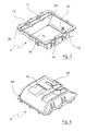
- la
figure 1 est une vue schématique en perspective d'une boîte de transmission selon un mode de réalisation de l'invention, - la
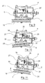
figure 2 est une vue schématique en perspective d'une boîte de transmission selon un mode de réalisation de l'invention comprenant un arbre d'entrée équipé d'un disque d'entraînement de marche avant et d'un variateur de vitesses, et sur laquelle la demi-coque supérieure n'est pas représentée, - la
figure 3 est une vue schématique en perspective de la boîte de transmission de lafigure 2 comprenant en outre un disque d'entraînement de marche arrière, et sur laquelle la demi-coque supérieure n'est pas représentée, - la
figure 4 est une vue schématique en perspective de la boîte de transmission de lafigure 3 comprenant en outre un frein, et sur laquelle la demi-coque supérieure n'est pas représentée, - la
figure 5 est une vue de dessus de la boîte de transmission de lafigure 3 , et sur laquelle la demi-coque supérieure n'est pas représentée, - la
figure 6 est une vue de dessus d'une boîte de transmission selon un mode de réalisation de l'invention, - la
figure 7 est une vue schématique en perspective d'une demi-coque inférieure d'une boîte de transmission selon un mode de réalisation de l'invention, - la
figure 8 est une vue schématique en perspective d'une demi-coque supérieure d'une boîte de transmission selon un mode de réalisation de l'invention, - la
figure 9 est une vue schématique arrière d'une boîte de transmission selon un mode de réalisation de l'invention en position
- the
figure 1 is a schematic perspective view of a transmission box according to one embodiment of the invention, - the
figure 2 is a schematic perspective view of a gearbox according to an embodiment of the invention comprising an input shaft equipped with a forward drive disc and a variable speed drive, and on which the upper half-shell is not shown, - the
figure 3 is a schematic perspective view of the gearbox of thefigure 2 further comprising a reverse drive disc, and on which the upper half-shell is not shown, - the
figure 4 is a schematic perspective view of the gearbox of thefigure 3 further comprising a brake, and on which the upper half-shell is not shown, - the
figure 5 is a top view of the gearbox of thefigure 3 , and on which the upper half-shell is not shown, - the
figure 6 is a top view of a gearbox according to one embodiment of the invention, - the
figure 7 is a schematic perspective view of a lower half-shell of a gearbox according to one embodiment of the invention, - the
figure 8 is a schematic perspective view of an upper half-shell of a gearbox according to one embodiment of the invention, - the
figure 9 is a schematic rear view of a gearbox according to an embodiment of the invention in position
débrayée,
- la
figure 10 est une vue schématique arrière d'une boîte de transmission selon un mode de réalisation de l'invention en position de prise avant, - la
figure 11 est une vue schématique arrière d'une boîte de transmission selon un mode de réalisation de l'invention en position de prise arrière.
- the
figure 10 is a schematic rear view of a gearbox according to an embodiment of the invention in the forward setting position, - the
figure 11 is a schematic rear view of a gearbox according to an embodiment of the invention in the rearward position.
Sur les figures, les échelles et les proportions ne sont pas strictement respectées et ce à des fins d'illustration et de clarté.Figures, scales and proportions are not strictly adhered to for the purpose of illustration and clarity.
Dans toute la description détaillée qui suit en référence aux figures, sauf indication contraire, chaque pièce de la boîte de transmission est décrite telle qu'elle est agencée lorsque la boîte est montée sur un équipement automoteur de débroussaillage. Cet agencement est représenté notamment sur la
Une boîte de transmission selon l'invention comprend un carter 1 formé de deux demi-coques 4, 5 agencées en regard l'une de l'autre de manière à former notamment un logement de réception d'un arbre 2 d'entrée.A gearbox according to the invention comprises a
Ce logement de réception présente une forme et des dimensions conformées et conjuguées à la forme et aux dimensions d'une pluralité de configurations distinctes possibles de l'arbre 2 d'entrée.This receiving housing has a shape and dimensions shaped and combined with the shape and dimensions of a plurality of possible distinct configurations of the
Selon le mode de réalisation des figures, quatre configurations distinctes sont possibles :
- (i) une configuration dans laquelle l'arbre d'entrée est équipé d'un disque d'entraînement en marche avant,
- (ii) une configuration dans laquelle l'arbre d'entrée est équipé d'un disque d'entraînement en marche avant et d'un variateur de vitesses,
- (iii) une configuration dans laquelle l'arbre d'entrée est équipé d'un disque d'entraînement en marche avant et d'un disque d'entraînement en marche arrière,
- (iv) une configuration dans laquelle l'arbre d'entrée est équipé d'un disque d'entraînement en marche avant, d'un variateur de vitesses, et d'un disque d'entraînement en marche arrière.
- (i) a configuration in which the input shaft is equipped with a drive disc in the forward direction,
- (ii) a configuration in which the input shaft is equipped with a forward drive disk and a variable speed drive,
- (iii) a configuration in which the input shaft is equipped with a forward drive disc and a drive disc in reverse,
- (iv) a configuration in which the input shaft is equipped with a drive disk in forward, a variable speed drive, and a drive disk in reverse.
La
Sur la
L'amplitude du déplacement du disque 6 d'entraînement en marche avant résultant de la commande de la fourchette 9 de commande est représenté sur la
L'actionnement de cette fourchette 9 de commande peut également être actionné par l'intermédiaire d'un câble de commande. Ce câble est selon un mode de réalisation logé en partie dans une zone de réception et de guidage d'une gaine portant ce câble de commande.The actuation of this
La
La forme et les dimensions du logement de réception de l'arbre 2 d'entrée formé par les demi-coques 4, 5 du carter de la boîte permettent de recevoir l'ensemble des configurations (i), (ii), (iii) et (iv) sans néanmoins imposer une modification de forme, de dimension, d'emplacement des autres organes de la boîte de transmission.The shape and the dimensions of the receiving housing of the
En particulier, une boîte selon l'invention comprend en outre un arbre 3 de sortie relié à l'arbre 2 d'entrée par l'intermédiaire de moyens d'engrènement.In particular, a box according to the invention further comprises an
L'arbre 3 de sortie et les moyens d'engrènement sont notamment représentés sur la
L'arbre 3 de sortie est porté par demi-réceptacles formant des paliers 13, 14 ménagé dans la demi-coque 5 inférieure. L'arbre 2 d'entrée est porté par des paliers 11, 12 ménagés dans la demi-coque 5 inférieure. Les paliers 11, 12, 13, 14 sont ménagés de telle sorte que les arbres sont parallèles l'un à l'autre.The
L'arbre 2 d'entrée comprend un pignon 15 denté agencé à une extrémité de l'arbre et l'arbre 3 de sortie comprend également un pignon 16 denté agencé sur l'arbre en regard du pignon 15 de l'arbre 2 de sorte qu'une chaîne 17 puisse reliée les pignons 15, 16 et ainsi transmettre le mouvement de rotation de l'arbre 2 d'entrée à l'arbre 3 de sortie.The
Le rapport de transmission résultant du rapport entre le diamètre du pignon 16 de l'arbre 3 de sortie et le diamètre du pignon 15 de l'arbre 2 d'entrée peut être choisi selon les besoins. En particulier, il est aisé de changer le pignon 16 de l'arbre 2 de sortie sans imposer une modification des autres organes de la transmission. Dès lors, le rapport de transmission peut être modifié.The transmission ratio resulting from the ratio between the diameter of the pinion 16 of the
L'arbre 2 de sortie présente en outre à une extrémité un pignon 18 de sortie de boîte. Ce pignon 18 de sortie de boîte est destiné à être relié aux moyens d'entraînement de l'équipement de débroussaillage, qui sont par exemple des roues.
Tel que représenté notamment sur les
En outre, une poulie 19 est montée pivotante sous la demi-coque 5 inférieure selon un axe diamétral de la poulie, en regard de ladite ouverture 50.In addition, a
Le montage de la poulie 19 sur la demi-coque 5 est réalisé par l'intermédiaire d'un balancier 20. Ce balancier 20 présente une forme générale de U étiré dont les deux branches du U comprennent un alésage 43 en regard d'alésages 22 aménagé sur deux bords latéraux de le demi-coque 5 inférieure de manière à pouvoir y loger une tige 21 formant un axe de pivotement. Ainsi, le balancier 20 peut pivoter par rapport à la demi-coque 5 inférieure suivant l'axe de pivotement défini par la tige 21. En outre, le balancier 20 présente un alésage central vertical agencé à mi-distance entre les deux branches du U de manière à pouvoir recevoir un système du type vis écrou 23 pour solidariser la poulie 19 au balancier 20. Une fois la poulie 19 montée sur le balancier, lui-même monté pivotant sur la demi-coque 5, la poulie 19 s'étend dans un plan sensiblement parallèle à la direction de l'arbre 2 d'entrée.The
La poulie 19 présente deux joues 24 et une gorge adaptée pour recevoir une courroie d'entraînement. La poulie 19 est adaptée pour être entraînée en rotation par des moyens moteurs du équipement de débroussaillage sur lequel la boîte de transmission selon l'invention est montée.The
Selon un mode de réalisation avantageux de l'invention, la joue 24 supérieure en regard de la demi-coque 5 inférieure est légèrement tronconique de sorte que la distance entre la joue 24 et la demi-coque 5 inférieure est plus grande au niveau de la périphérie de la joue 24 qu'au centre de la joue 24.According to an advantageous embodiment of the invention, the
La poulie 19 montée sur le balancier 20 est adaptée pour prendre au moins une position en prise avant, dans laquelle la joue 24 joue supérieure de la poulie entraîne en rotation par friction la portion périphérique du disque 6 d'entraînement en marche avant s'étendant à travers l'ouverture 50. Cette position correspond à un pivotement du balancier 20 vers le disque 6 d'entraînement en marche avant.The
La poulie 19 est également adaptée pour prendre une position en prise arrière dans laquelle la joue 24 joue supérieure de la poulie entraîne en rotation par friction la portion périphérique du disque 7 d'entraînement en marche arrière s'étendant à travers l'ouverture 50. Cette position correspond à un pivotement du balancier 20 vers le disque 7 d'entraînement en marche arrière.The
Pour améliorer la friction entre la joue 24 supérieure de la poulie 19 et les disques 6, 7 d'entraînement, chaque disque comprend un revêtement périphérique en caoutchouc. Selon un autre mode de réalisation, ce revêtement est faite en EPDM.To improve the friction between the upper cheek of the
Lorsque la poulie 19 n'est basculée ni du côté du disque 6 d'entraînement en marche avant, ni du côté du disque 7 d'entraînement en marche arrière, la poulie 19 est dans une position débrayée dans laquelle l'arbre 2 d'entrée n'est pas entraîné en rotation.When the
La
La
La
Selon un mode de réalisation avantageux de l'invention et tel que représenté notamment sur les
Ce levier s'étend au-delà de l'arbre 2 d'entrée de sorte à pouvoir occuper une position, dite position freinée, dans laquelle le levier 25 est en appui sur le disque 7 d'entraînement de marche arrière au niveau de la courbure du levier pour bloquer toute rotation de l'arbre 2 d'entrée. De préférence, la courbure du levier est sensiblement égale à la courbure du disque 7 de sorte qu'une fois en appui, la surface de contact entre le levier et le disque 7 soit la plus grande possible.This lever extends beyond the
Le levier peut également être pivoté autour de l'axe 3 de sortie auquel il est relié pour pouvoir occuper une position, dite position libérée, dans laquelle ledit levier est éloigné du disque 7 d'entraînement de marche arrière de manière à autoriser la rotation de l'arbre 2 d'entrée.The lever may also be pivoted about the
Le maintien du levier 25 de frein dans la position freinée est assuré par un ressort 37 agencé entre le levier 25 de frein et la demi-coque 4 supérieure. Ainsi, le levier de frein est dans la position freinée par défaut. Seule une action sur ce levier de frein, comme décrit ci-après, permet de le déplacer de la position freinée à la position libérée.Maintaining the
Ce levier 25 de frein présente une aile 26 agencée à l'extrémité opposée de la liaison pivot avec l'arbre 3 de sortie. Cette aile 26 s'étend dans un plan sensiblement horizontal et parallèle au plan de la poulie 19. Cette aile 26 maintient en outre deux entretoises 27, 28 métalliques qui s'étendent dans un plan sensiblement perpendiculaire au plan de l'aile 26. Ces entretoises 27, 28 s'étendent entre l'aile 26 du levier 25 de frein et le balancier 20. En particulier, le balancier 20 comprend deux ailettes 30, 31 qui s'étendent dans un plan horizontal perpendiculaire aux entretoises 27, 28. Ainsi, dans la position débrayée, les entretoises s'étendent exactement entre l'aile 26 et les ailettes 30, 31. Ces ailettes 30, 31 forment des butées de libération de frein. En particulier, lorsque le balancier bascule sur un côté, par exemple sur le côté de la marche avant tel que représenté sur la
De même, lorsque le balancier bascule de l'autre côté, tel que représenté sur la
Selon un mode de réalisation avantageux, la boîte de transmission comprend également une poignée 33 de manoeuvre du levier 35 de frein pour le déplacer manuellement de la position freinée à la position libérée et inversement.According to an advantageous embodiment, the gearbox also comprises a
Selon le mode de réalisation des figures, la poignée de manoeuvre est montée pivotante selon un axe coïncidant avec l'axe de la tige 21 de pivotement du balancier 20. Cette poignée 33 de manoeuvre présente en outre une portion adaptée pour venir en contact avec le levier 25 de frein pour permettre de le déplacer de la position freinée à la position libérée.According to the embodiment of the figures, the operating handle is pivotally mounted along an axis coinciding with the axis of the
Pour ce faire, l'aile 26 du levier 25 de frein est prolongée par un retour 34, représenté notamment sur les
Les demis-coques 4, 5 illustrées sur les
La demi-coque 5 inférieure comprend en outre un logement de propreté destiné à recevoir lesdits moyens 15, 16, 17 d'engrènement, défini par un bord intérieur de ladite demi-coque 5 inférieure, une première demi-cloison 52 s'étendant sensiblement perpendiculairement aux arbres 2, 3 et une portion de fond reliant ladite cloison et ledit bord intérieur.The lower half-
La demi-coque 4 supérieure comprend une seconde demi-cloison 42 complémentaire de ladite première demi-cloison 52, de façon à fermer ledit logement de propreté. Ce logement de propreté permet d'isoler les moyens d'engrènement des autres organes de la transmission.The upper half-
L'invention ne se limite pas aux seuls modes de réalisation décrits. En particulier, la boîte de transmission peut être configurée de sorte à recevoir d'autres configurations de l'arbre d'entrée, par exemple un variateur de vitesses de la marche arrière.The invention is not limited to the embodiments described. In particular, the gearbox can be configured to receive other configurations of the input shaft, for example a reversing speed variator.
Une boîte de transmission selon l'invention peut être montée sur tous types d'équipement de débroussaillage, tel qu'un véhicule de débroussaillage, un équipement à conducteur marchant ou un dispositif analogue.A gearbox according to the invention can be mounted on all types of brushcutter equipment, such as a brushcutter, walkman equipment or the like.
Claims (16)
et en ce que ledit carter est formé de deux demi-coques, dites respectivement demi-coque (5) inférieure et demi-coque (4) supérieure, agencées en regard l'une de l'autre et définissant un logement de réception de l'arbre (2) d'entrée, ledit logement de réception présentant une forme et des dimensions conformées et conjuguées à la forme et aux dimensions d'au moins trois configurations distinctes de l'arbre (2) d' entrée :
and in that said housing is formed of two half-shells, respectively called lower half-shell (5) and upper half-shell (4), arranged facing one another and defining a receiving housing of the input shaft (2), said receiving housing having a shape and dimensions shaped and conjugate in shape and dimensions of at least three distinct configurations of the input shaft (2):
et en ce que ladite poulie (19) est montée pivotante sous ladite demi-coque (5) inférieure en regard de ladite ouverture (50), ladite poulie (19) étant adaptée pour prendre :
and in that said pulley (19) is pivotally mounted under said lower half-shell (5) facing said opening (50), said pulley (19) being adapted to take:
Applications Claiming Priority (1)
| Application Number | Priority Date | Filing Date | Title |
|---|---|---|---|
| FR0954683A FR2947695B1 (en) | 2009-07-07 | 2009-07-07 | TRANSMISSION BOX FOR AUTOMOTIVE BRACKET EQUIPMENT AND AUTOMOTIVE BRUSHING DEVICE COMPRISING SUCH |
Publications (2)
| Publication Number | Publication Date |
|---|---|
| EP2273155A1 true EP2273155A1 (en) | 2011-01-12 |
| EP2273155B1 EP2273155B1 (en) | 2013-11-27 |
Family
ID=41404292
Family Applications (1)
| Application Number | Title | Priority Date | Filing Date |
|---|---|---|---|
| EP10168376.1A Active EP2273155B1 (en) | 2009-07-07 | 2010-07-02 | Transmission for a self-propelled tiller and tiller with a respective transmission |
Country Status (3)
| Country | Link |
|---|---|
| EP (1) | EP2273155B1 (en) |
| ES (1) | ES2445875T3 (en) |
| FR (1) | FR2947695B1 (en) |
Cited By (1)
| Publication number | Priority date | Publication date | Assignee | Title |
|---|---|---|---|---|
| CN111492736A (en) * | 2020-05-19 | 2020-08-07 | 台州科技职业学院 | Electric mini-tiller |
Citations (5)
| Publication number | Priority date | Publication date | Assignee | Title |
|---|---|---|---|---|
| DE55629C (en) * | W. VON PITTLER in Gohlis-Leipzig | Friction transmission for changing the direction and speed of rotation | ||
| CH94340A (en) * | 1919-11-10 | 1922-05-01 | Fischer Martin | Face plate gear for motor vehicles. |
| US5353578A (en) * | 1993-03-02 | 1994-10-11 | Fuqua Industries, Inc. | Drive system for lawn mowers |
| FR2703876A1 (en) * | 1993-04-14 | 1994-10-21 | Honda Motor Co Ltd | Motorised cultivator which can operate in rotation in the normal direction and in the opposite direction |
| US20080110689A1 (en) * | 2006-10-05 | 2008-05-15 | Mcdaniel Andrew Joseph | Linearly adjustable torque transmission systems and methods |
-
2009
- 2009-07-07 FR FR0954683A patent/FR2947695B1/en not_active Expired - Fee Related
-
2010
- 2010-07-02 ES ES10168376T patent/ES2445875T3/en active Active
- 2010-07-02 EP EP10168376.1A patent/EP2273155B1/en active Active
Patent Citations (5)
| Publication number | Priority date | Publication date | Assignee | Title |
|---|---|---|---|---|
| DE55629C (en) * | W. VON PITTLER in Gohlis-Leipzig | Friction transmission for changing the direction and speed of rotation | ||
| CH94340A (en) * | 1919-11-10 | 1922-05-01 | Fischer Martin | Face plate gear for motor vehicles. |
| US5353578A (en) * | 1993-03-02 | 1994-10-11 | Fuqua Industries, Inc. | Drive system for lawn mowers |
| FR2703876A1 (en) * | 1993-04-14 | 1994-10-21 | Honda Motor Co Ltd | Motorised cultivator which can operate in rotation in the normal direction and in the opposite direction |
| US20080110689A1 (en) * | 2006-10-05 | 2008-05-15 | Mcdaniel Andrew Joseph | Linearly adjustable torque transmission systems and methods |
Cited By (1)
| Publication number | Priority date | Publication date | Assignee | Title |
|---|---|---|---|---|
| CN111492736A (en) * | 2020-05-19 | 2020-08-07 | 台州科技职业学院 | Electric mini-tiller |
Also Published As
| Publication number | Publication date |
|---|---|
| EP2273155B1 (en) | 2013-11-27 |
| FR2947695B1 (en) | 2011-08-19 |
| FR2947695A1 (en) | 2011-01-14 |
| ES2445875T3 (en) | 2014-03-05 |
Similar Documents
| Publication | Publication Date | Title |
|---|---|---|
| WO2002050387A1 (en) | Self-propelled running apparatus for cleaning immersed surface comprising detachable running member(s) | |
| EP2989341A1 (en) | Transmission for a wheeled vehicle with a walking driver, and wheeled vehicle equipped with such a transmission | |
| EP2627928B1 (en) | Gearbox for mechanism farming implement and mechanized farming implement comprising such a gearbox | |
| FR2487934A1 (en) | CLUTCH CLUTCH FOR MOTORCYCLE | |
| EP2829470B1 (en) | Device for rotating an aircraft wheel | |
| FR2946290A1 (en) | TRANSMISSION DEVICE AND AUTOMOTIVE DEVICE EQUIPPED WITH SUCH A TRANSMISSION DEVICE | |
| FR2795145A1 (en) | Clutch mechanism for motorized wheelbarrow or lawn mower has driving and driven parts coupled by clutch rollers in cooperation due to jamming effect | |
| EP2273155B1 (en) | Transmission for a self-propelled tiller and tiller with a respective transmission | |
| FR2631775A1 (en) | AGRICULTURAL MACHINE HAVING AT LEAST ONE ROTOR ROTATING IN ROTATION DURING WORK | |
| EP1775498B1 (en) | Transmission for a motorized agricultural working vehicle | |
| EP0188164A1 (en) | Steering unit for an automotive vehicle with a fixed central cushion | |
| FR2946405A1 (en) | DEVICE FOR REVERSING THE DIRECTION OF THE WALKING OF A AUTOMOTIVE ROLLER | |
| EP0717920B1 (en) | Riding machine with driven wheels such as lawn- or brushmower | |
| EP0826580B1 (en) | Improved motorized agricultural working vehicle | |
| EP2631162B1 (en) | Sequential gearshift lever for bicycle | |
| EP3625481B1 (en) | Gearbox for mechanized farming implement and mechanized farming implement comprising such a gearbox | |
| WO2022167989A1 (en) | Motorised device intended to be attached to a vehicle wheel to move same | |
| FR2896554A1 (en) | Idle pinion coupling device for vehicle, has coupling unit controlled in independent manner with respect to another coupling unit and ensuring equalization of rotation speed of pinion with rotation speed of shaft of gearbox by friction | |
| EP1523232B1 (en) | Hay making machine | |
| FR3008955A1 (en) | DEVICE FOR DRIVING ROTATION OF AN AIRCRAFT WHEEL | |
| EP2631163B1 (en) | Gearshift lever for bicycle including a displacement restrictor | |
| FR2587295A1 (en) | TRANSMISSION DEVICE FOR MOTORIZED VEHICLE WITH TWO WHEELS | |
| FR2849131A1 (en) | Driving device for infant tricycle comprises first cylindrical part with inclined teeth forming part of bearing and second cylindrical part forming second bearing part with housing for pawl engaging teeth creating unidirectional connection | |
| FR2825124A1 (en) | Two speed lawn mower for cutting the grass comprises a chassis carrying a front wheel and circular cutting casing on which I.C. engine is mounted | |
| FR2853946A1 (en) | Rotary tiller or two wheeled tractor machine, has tension device at level of driven pulley, to act on tension of transmission belts by moving center of rotation of two pulleys in direction extending from drive pulley |
Legal Events
| Date | Code | Title | Description |
|---|---|---|---|
| PUAI | Public reference made under article 153(3) epc to a published international application that has entered the european phase |
Free format text: ORIGINAL CODE: 0009012 |
|
| AK | Designated contracting states |
Kind code of ref document: A1 Designated state(s): AL AT BE BG CH CY CZ DE DK EE ES FI FR GB GR HR HU IE IS IT LI LT LU LV MC MK MT NL NO PL PT RO SE SI SK SM TR |
|
| AX | Request for extension of the european patent |
Extension state: BA ME RS |
|
| 17P | Request for examination filed |
Effective date: 20110628 |
|
| REG | Reference to a national code |
Ref country code: DE Ref legal event code: R079 Ref document number: 602010012011 Country of ref document: DE Free format text: PREVIOUS MAIN CLASS: F16H0015100000 Ipc: A01D0069060000 |
|
| GRAP | Despatch of communication of intention to grant a patent |
Free format text: ORIGINAL CODE: EPIDOSNIGR1 |
|
| RIC1 | Information provided on ipc code assigned before grant |
Ipc: A01D 69/06 20060101AFI20130225BHEP Ipc: A01B 33/08 20060101ALI20130225BHEP Ipc: F16H 15/10 20060101ALI20130225BHEP |
|
| GRAS | Grant fee paid |
Free format text: ORIGINAL CODE: EPIDOSNIGR3 |
|
| GRAP | Despatch of communication of intention to grant a patent |
Free format text: ORIGINAL CODE: EPIDOSNIGR1 |
|
| INTG | Intention to grant announced |
Effective date: 20130903 |
|
| GRAA | (expected) grant |
Free format text: ORIGINAL CODE: 0009210 |
|
| AK | Designated contracting states |
Kind code of ref document: B1 Designated state(s): AL AT BE BG CH CY CZ DE DK EE ES FI FR GB GR HR HU IE IS IT LI LT LU LV MC MK MT NL NO PL PT RO SE SI SK SM TR |
|
| REG | Reference to a national code |
Ref country code: GB Ref legal event code: FG4D Free format text: NOT ENGLISH |
|
| REG | Reference to a national code |
Ref country code: CH Ref legal event code: EP |
|
| REG | Reference to a national code |
Ref country code: AT Ref legal event code: REF Ref document number: 642298 Country of ref document: AT Kind code of ref document: T Effective date: 20131215 |
|
| REG | Reference to a national code |
Ref country code: IE Ref legal event code: FG4D Free format text: LANGUAGE OF EP DOCUMENT: FRENCH |
|
| REG | Reference to a national code |
Ref country code: DE Ref legal event code: R096 Ref document number: 602010012011 Country of ref document: DE Effective date: 20140123 |
|
| REG | Reference to a national code |
Ref country code: ES Ref legal event code: FG2A Ref document number: 2445875 Country of ref document: ES Kind code of ref document: T3 Effective date: 20140305 |
|
| REG | Reference to a national code |
Ref country code: NL Ref legal event code: VDEP Effective date: 20131127 |
|
| REG | Reference to a national code |
Ref country code: AT Ref legal event code: MK05 Ref document number: 642298 Country of ref document: AT Kind code of ref document: T Effective date: 20131127 |
|
| REG | Reference to a national code |
Ref country code: LT Ref legal event code: MG4D |
|
| PG25 | Lapsed in a contracting state [announced via postgrant information from national office to epo] |
Ref country code: HR Free format text: LAPSE BECAUSE OF FAILURE TO SUBMIT A TRANSLATION OF THE DESCRIPTION OR TO PAY THE FEE WITHIN THE PRESCRIBED TIME-LIMIT Effective date: 20131127 Ref country code: FI Free format text: LAPSE BECAUSE OF FAILURE TO SUBMIT A TRANSLATION OF THE DESCRIPTION OR TO PAY THE FEE WITHIN THE PRESCRIBED TIME-LIMIT Effective date: 20131127 Ref country code: SE Free format text: LAPSE BECAUSE OF FAILURE TO SUBMIT A TRANSLATION OF THE DESCRIPTION OR TO PAY THE FEE WITHIN THE PRESCRIBED TIME-LIMIT Effective date: 20131127 Ref country code: NL Free format text: LAPSE BECAUSE OF FAILURE TO SUBMIT A TRANSLATION OF THE DESCRIPTION OR TO PAY THE FEE WITHIN THE PRESCRIBED TIME-LIMIT Effective date: 20131127 Ref country code: NO Free format text: LAPSE BECAUSE OF FAILURE TO SUBMIT A TRANSLATION OF THE DESCRIPTION OR TO PAY THE FEE WITHIN THE PRESCRIBED TIME-LIMIT Effective date: 20140227 Ref country code: LT Free format text: LAPSE BECAUSE OF FAILURE TO SUBMIT A TRANSLATION OF THE DESCRIPTION OR TO PAY THE FEE WITHIN THE PRESCRIBED TIME-LIMIT Effective date: 20131127 Ref country code: IS Free format text: LAPSE BECAUSE OF FAILURE TO SUBMIT A TRANSLATION OF THE DESCRIPTION OR TO PAY THE FEE WITHIN THE PRESCRIBED TIME-LIMIT Effective date: 20140327 |
|
| PG25 | Lapsed in a contracting state [announced via postgrant information from national office to epo] |
Ref country code: LV Free format text: LAPSE BECAUSE OF FAILURE TO SUBMIT A TRANSLATION OF THE DESCRIPTION OR TO PAY THE FEE WITHIN THE PRESCRIBED TIME-LIMIT Effective date: 20131127 Ref country code: CY Free format text: LAPSE BECAUSE OF FAILURE TO SUBMIT A TRANSLATION OF THE DESCRIPTION OR TO PAY THE FEE WITHIN THE PRESCRIBED TIME-LIMIT Effective date: 20131127 Ref country code: AT Free format text: LAPSE BECAUSE OF FAILURE TO SUBMIT A TRANSLATION OF THE DESCRIPTION OR TO PAY THE FEE WITHIN THE PRESCRIBED TIME-LIMIT Effective date: 20131127 |
|
| PG25 | Lapsed in a contracting state [announced via postgrant information from national office to epo] |
Ref country code: PT Free format text: LAPSE BECAUSE OF FAILURE TO SUBMIT A TRANSLATION OF THE DESCRIPTION OR TO PAY THE FEE WITHIN THE PRESCRIBED TIME-LIMIT Effective date: 20140327 |
|
| PG25 | Lapsed in a contracting state [announced via postgrant information from national office to epo] |
Ref country code: EE Free format text: LAPSE BECAUSE OF FAILURE TO SUBMIT A TRANSLATION OF THE DESCRIPTION OR TO PAY THE FEE WITHIN THE PRESCRIBED TIME-LIMIT Effective date: 20131127 |
|
| REG | Reference to a national code |
Ref country code: DE Ref legal event code: R097 Ref document number: 602010012011 Country of ref document: DE |
|
| PG25 | Lapsed in a contracting state [announced via postgrant information from national office to epo] |
Ref country code: CZ Free format text: LAPSE BECAUSE OF FAILURE TO SUBMIT A TRANSLATION OF THE DESCRIPTION OR TO PAY THE FEE WITHIN THE PRESCRIBED TIME-LIMIT Effective date: 20131127 Ref country code: SK Free format text: LAPSE BECAUSE OF FAILURE TO SUBMIT A TRANSLATION OF THE DESCRIPTION OR TO PAY THE FEE WITHIN THE PRESCRIBED TIME-LIMIT Effective date: 20131127 Ref country code: PL Free format text: LAPSE BECAUSE OF FAILURE TO SUBMIT A TRANSLATION OF THE DESCRIPTION OR TO PAY THE FEE WITHIN THE PRESCRIBED TIME-LIMIT Effective date: 20131127 Ref country code: RO Free format text: LAPSE BECAUSE OF FAILURE TO SUBMIT A TRANSLATION OF THE DESCRIPTION OR TO PAY THE FEE WITHIN THE PRESCRIBED TIME-LIMIT Effective date: 20131127 |
|
| PG25 | Lapsed in a contracting state [announced via postgrant information from national office to epo] |
Ref country code: DK Free format text: LAPSE BECAUSE OF FAILURE TO SUBMIT A TRANSLATION OF THE DESCRIPTION OR TO PAY THE FEE WITHIN THE PRESCRIBED TIME-LIMIT Effective date: 20131127 |
|
| PLBE | No opposition filed within time limit |
Free format text: ORIGINAL CODE: 0009261 |
|
| STAA | Information on the status of an ep patent application or granted ep patent |
Free format text: STATUS: NO OPPOSITION FILED WITHIN TIME LIMIT |
|
| 26N | No opposition filed |
Effective date: 20140828 |
|
| REG | Reference to a national code |
Ref country code: DE Ref legal event code: R097 Ref document number: 602010012011 Country of ref document: DE Effective date: 20140828 |
|
| PG25 | Lapsed in a contracting state [announced via postgrant information from national office to epo] |
Ref country code: SI Free format text: LAPSE BECAUSE OF FAILURE TO SUBMIT A TRANSLATION OF THE DESCRIPTION OR TO PAY THE FEE WITHIN THE PRESCRIBED TIME-LIMIT Effective date: 20131127 Ref country code: LU Free format text: LAPSE BECAUSE OF FAILURE TO SUBMIT A TRANSLATION OF THE DESCRIPTION OR TO PAY THE FEE WITHIN THE PRESCRIBED TIME-LIMIT Effective date: 20140702 |
|
| REG | Reference to a national code |
Ref country code: CH Ref legal event code: PL |
|
| GBPC | Gb: european patent ceased through non-payment of renewal fee |
Effective date: 20140702 |
|
| REG | Reference to a national code |
Ref country code: IE Ref legal event code: MM4A |
|
| PG25 | Lapsed in a contracting state [announced via postgrant information from national office to epo] |
Ref country code: CH Free format text: LAPSE BECAUSE OF NON-PAYMENT OF DUE FEES Effective date: 20140731 Ref country code: LI Free format text: LAPSE BECAUSE OF NON-PAYMENT OF DUE FEES Effective date: 20140731 |
|
| PG25 | Lapsed in a contracting state [announced via postgrant information from national office to epo] |
Ref country code: GB Free format text: LAPSE BECAUSE OF NON-PAYMENT OF DUE FEES Effective date: 20140702 |
|
| PG25 | Lapsed in a contracting state [announced via postgrant information from national office to epo] |
Ref country code: IE Free format text: LAPSE BECAUSE OF NON-PAYMENT OF DUE FEES Effective date: 20140702 |
|
| PG25 | Lapsed in a contracting state [announced via postgrant information from national office to epo] |
Ref country code: SM Free format text: LAPSE BECAUSE OF FAILURE TO SUBMIT A TRANSLATION OF THE DESCRIPTION OR TO PAY THE FEE WITHIN THE PRESCRIBED TIME-LIMIT Effective date: 20131127 Ref country code: MC Free format text: LAPSE BECAUSE OF FAILURE TO SUBMIT A TRANSLATION OF THE DESCRIPTION OR TO PAY THE FEE WITHIN THE PRESCRIBED TIME-LIMIT Effective date: 20131127 |
|
| PG25 | Lapsed in a contracting state [announced via postgrant information from national office to epo] |
Ref country code: GR Free format text: LAPSE BECAUSE OF FAILURE TO SUBMIT A TRANSLATION OF THE DESCRIPTION OR TO PAY THE FEE WITHIN THE PRESCRIBED TIME-LIMIT Effective date: 20140228 Ref country code: BG Free format text: LAPSE BECAUSE OF FAILURE TO SUBMIT A TRANSLATION OF THE DESCRIPTION OR TO PAY THE FEE WITHIN THE PRESCRIBED TIME-LIMIT Effective date: 20131127 Ref country code: MT Free format text: LAPSE BECAUSE OF FAILURE TO SUBMIT A TRANSLATION OF THE DESCRIPTION OR TO PAY THE FEE WITHIN THE PRESCRIBED TIME-LIMIT Effective date: 20131127 |
|
| REG | Reference to a national code |
Ref country code: FR Ref legal event code: PLFP Year of fee payment: 7 |
|
| PG25 | Lapsed in a contracting state [announced via postgrant information from national office to epo] |
Ref country code: BE Free format text: LAPSE BECAUSE OF FAILURE TO SUBMIT A TRANSLATION OF THE DESCRIPTION OR TO PAY THE FEE WITHIN THE PRESCRIBED TIME-LIMIT Effective date: 20140731 Ref country code: HU Free format text: LAPSE BECAUSE OF FAILURE TO SUBMIT A TRANSLATION OF THE DESCRIPTION OR TO PAY THE FEE WITHIN THE PRESCRIBED TIME-LIMIT; INVALID AB INITIO Effective date: 20100702 Ref country code: TR Free format text: LAPSE BECAUSE OF FAILURE TO SUBMIT A TRANSLATION OF THE DESCRIPTION OR TO PAY THE FEE WITHIN THE PRESCRIBED TIME-LIMIT Effective date: 20131127 |
|
| REG | Reference to a national code |
Ref country code: FR Ref legal event code: PLFP Year of fee payment: 8 |
|
| PG25 | Lapsed in a contracting state [announced via postgrant information from national office to epo] |
Ref country code: MK Free format text: LAPSE BECAUSE OF FAILURE TO SUBMIT A TRANSLATION OF THE DESCRIPTION OR TO PAY THE FEE WITHIN THE PRESCRIBED TIME-LIMIT Effective date: 20131127 |
|
| REG | Reference to a national code |
Ref country code: FR Ref legal event code: PLFP Year of fee payment: 9 |
|
| PG25 | Lapsed in a contracting state [announced via postgrant information from national office to epo] |
Ref country code: AL Free format text: LAPSE BECAUSE OF FAILURE TO SUBMIT A TRANSLATION OF THE DESCRIPTION OR TO PAY THE FEE WITHIN THE PRESCRIBED TIME-LIMIT Effective date: 20131127 |
|
| P01 | Opt-out of the competence of the unified patent court (upc) registered |
Effective date: 20230517 |
|
| PGFP | Annual fee paid to national office [announced via postgrant information from national office to epo] |
Ref country code: IT Payment date: 20230621 Year of fee payment: 14 Ref country code: ES Payment date: 20230928 Year of fee payment: 14 |
|
| PGFP | Annual fee paid to national office [announced via postgrant information from national office to epo] |
Ref country code: FR Payment date: 20230727 Year of fee payment: 14 Ref country code: DE Payment date: 20230724 Year of fee payment: 14 |