EP2272320A1 - Drive roller for driving at least one flat belt - Google Patents
Drive roller for driving at least one flat belt Download PDFInfo
- Publication number
- EP2272320A1 EP2272320A1 EP10167554A EP10167554A EP2272320A1 EP 2272320 A1 EP2272320 A1 EP 2272320A1 EP 10167554 A EP10167554 A EP 10167554A EP 10167554 A EP10167554 A EP 10167554A EP 2272320 A1 EP2272320 A1 EP 2272320A1
- Authority
- EP
- European Patent Office
- Prior art keywords
- drive roller
- lagging
- grooves
- roller according
- previous
- Prior art date
- Legal status (The legal status is an assumption and is not a legal conclusion. Google has not performed a legal analysis and makes no representation as to the accuracy of the status listed.)
- Granted
Links
Images




Classifications
-
- A—HUMAN NECESSITIES
- A01—AGRICULTURE; FORESTRY; ANIMAL HUSBANDRY; HUNTING; TRAPPING; FISHING
- A01F—PROCESSING OF HARVESTED PRODUCE; HAY OR STRAW PRESSES; DEVICES FOR STORING AGRICULTURAL OR HORTICULTURAL PRODUCE
- A01F15/00—Baling presses for straw, hay or the like
- A01F15/08—Details
- A01F15/18—Endless belts, rolls or the like
-
- B—PERFORMING OPERATIONS; TRANSPORTING
- B65—CONVEYING; PACKING; STORING; HANDLING THIN OR FILAMENTARY MATERIAL
- B65G—TRANSPORT OR STORAGE DEVICES, e.g. CONVEYORS FOR LOADING OR TIPPING, SHOP CONVEYOR SYSTEMS OR PNEUMATIC TUBE CONVEYORS
- B65G15/00—Conveyors having endless load-conveying surfaces, i.e. belts and like continuous members, to which tractive effort is transmitted by means other than endless driving elements of similar configuration
- B65G15/30—Belts or like endless load-carriers
- B65G15/50—Endless load-carriers consisting of a series of parallel ropes or belt strips
-
- B—PERFORMING OPERATIONS; TRANSPORTING
- B65—CONVEYING; PACKING; STORING; HANDLING THIN OR FILAMENTARY MATERIAL
- B65G—TRANSPORT OR STORAGE DEVICES, e.g. CONVEYORS FOR LOADING OR TIPPING, SHOP CONVEYOR SYSTEMS OR PNEUMATIC TUBE CONVEYORS
- B65G39/00—Rollers, e.g. drive rollers, or arrangements thereof incorporated in roller-ways or other types of mechanical conveyors
- B65G39/02—Adaptations of individual rollers and supports therefor
- B65G39/07—Other adaptations of sleeves
- B65G39/071—Other adaptations of sleeves for aligning belts or sheets
-
- B—PERFORMING OPERATIONS; TRANSPORTING
- B65—CONVEYING; PACKING; STORING; HANDLING THIN OR FILAMENTARY MATERIAL
- B65G—TRANSPORT OR STORAGE DEVICES, e.g. CONVEYORS FOR LOADING OR TIPPING, SHOP CONVEYOR SYSTEMS OR PNEUMATIC TUBE CONVEYORS
- B65G39/00—Rollers, e.g. drive rollers, or arrangements thereof incorporated in roller-ways or other types of mechanical conveyors
- B65G39/02—Adaptations of individual rollers and supports therefor
- B65G39/07—Other adaptations of sleeves
- B65G39/073—Other adaptations of sleeves for cleaning belts
-
- A—HUMAN NECESSITIES
- A01—AGRICULTURE; FORESTRY; ANIMAL HUSBANDRY; HUNTING; TRAPPING; FISHING
- A01F—PROCESSING OF HARVESTED PRODUCE; HAY OR STRAW PRESSES; DEVICES FOR STORING AGRICULTURAL OR HORTICULTURAL PRODUCE
- A01F15/00—Baling presses for straw, hay or the like
- A01F15/08—Details
- A01F15/18—Endless belts, rolls or the like
- A01F2015/186—Constructional details of rollers or the bearings of the rollers of the press chamber
Definitions
- the present invention relates generally to a drive roller for driving at least one flat belt, the drive roller having a roller body with lagging applied thereto.
- Water, dust, or mud-like material can reduce the coefficient of friction between the drive roller and the flat belt.
- wet organic material wet silage
- This problem is aggravated by the fact that the wet organic material also has a tendency to adhere to the belts and rollers.
- the invention provides a drive roller for flat belts.
- a drive roller for driving at least one flat belt having a roller body with lagging applied thereto the lagging having a plurality of first grooves in a surface thereof that are substantially non-parallel to the direction of travel.
- drive roller for flat belts is provided in various embodiments wherein the roller has improved characteristics for maintaining traction of belts, such as lagging applied to the roller.
- a drive roller according to the invention is designated generally by the numeral 10.
- the drive roller 10 is illustrated in conjunction with a plurality of flat belts 12 in a configuration as might be found in an agricultural baler used for producing round or cylindrical crop bales.
- lagging 14 has been applied to the drive roller 10 and that the belts 12 are tensioned and trained in an endless loop around the roller 10 and at least a second roller (not shown), so that each belt 12 is in frictional contact with the lagging 14.
- the belts 12 move in the direction of the arrow B.
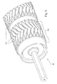
- the drive roller 10 is illustrated without the belts and it can be seen that the drive roller 10 consists of a cylindrical roller body 16 which is supported on a continuous shaft 18 or on stub shafts affixed to each end of the roller body 16.
- Lagging 14 is applied to the roller body 16 as will be described in more detail below.
- the lagging 14 may be in the form of an elastomeric material that is adhered to the roller body 16 or may be machined directly into the material of the roller body or on rigid non-elastomeric parts that are affixed to the roller body 16. In any case it will be seen that the lagging 14 is applied to the roller body 16 in discrete regions 20 that correspond to the belt locations illustrated in Fig. 1 .
- a plurality of grooves 24 are present in the lagging 14 for reasons which will be described in more detail below.
- the grooves 24 are arranged in a herringbone pattern about the circumference of the roller 10.
- Each groove 24 originates close to an imaginary centerline C circumscribing the discrete lagging region 20 and extends obliquely opposite the direction of rotation of the roller 10, as illustrated in Fig. 1 , to terminate with the edges of each discrete lagging region 20.
- the outside diameter of the lagging supports and drives the flat belt.
- Each groove provides a path for moisture or foreign objects to be displaced from the driving surface as such, it is preferable that the grooves empty to the side of the belt, if angled the tail of the groove can empty into an opening or channel in order to squeeze out and evacuate the accumulations.
- the edge of the groove (at the O.D.) is allowed to flex so as to provide a wiping action to clean the belt and grip the belt more effectively, the flexing action of this edge can also breakup accumulations on the roller surface.
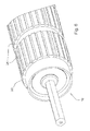
- roller 10A an alternative embodiment of the roller 10 is illustrated as 10A and is identical in all respects to the embodiment of Figs. 1 and 2 with the exception that the grooves 24A are not arranged in the herringbone pattern, but are instead oriented transversely across the circumferential face of each discrete lagging region 20.
- Fig. 4 it will be seen that another embodiment of the drive roller is illustrated as 10B.
- the grooves 24 are arranged in the herringbone pattern of Figs. 1 and 2 and a pair of additional circumferential grooves 26 circumscribe each discrete lagging region 20 on each side of the imaginary centerline C so as to intersect each of the obliquely oriented grooves extending from the centerline C.
- Fig. 5 another embodiment is shown wherein the grooves 24 have a varying size, shape and/or direction along their length so as to improve the flow path of the evacuated materials. More particularly, while the grooves 24 are arranged in the herringbone pattern, each groove acutely widens near it terminus at the edge of the discrete lagging region 20 to form a Y-Shape.
- Fig. 6 and 7 illustrate an embodiment wherein a rib 30 is provided along one side of each groove 24. As shown the rib 30 protrudes outwardly from the lagging surface. During operation of the drive roller 10 the raised ribs 30 provide a wiping action relative to the belt 12 thereby further enhancing the removal of extraneous material. As shown in Fig. 7 the wiping action occurs as the belt surface engages and disengages the lagging. More particularly, the belt 12 compresses the rib 30 as the belt engages the lagging and as the belt 12 disengages the lagging, the rib 30 springs back to provide a wiping action. Similarly as shown in Fig. 8 it is contemplated that the non-grooved areas 32 of the lagging could be made sufficiently narrow so as to be flexible enough to provide a similar wiping action without the need for a raised rib.
- Fig. 9 illustrates an embodiment wherein the elastomeric lagging 14 is provided with a plurality of rigid non-elastomeric protrusion 34, like studs or bumps. It has been found that the addition of such rigid protrusion (studs or bumps) enhances the ability of the lagging to break up accumulations of extraneous material entrained between the belt 12 and the roller 10 and improve traction between the belt and roller.
- rigid protrusion studs or bumps
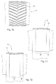
- Fig. 10 illustrates an embodiment wherein the lagging 14 is crowned so as to improve tracking of the belts 12 relative to the lagging 14.
- Figs. 11 and 12 illustrate embodiments wherein the lagging 14 has a varying diameter wherein certain areas 36 of the driving surface of the lagging have a larger outside diameter than other sections 38 so as to create a speed differential and create relative movement between the belts and roller for cleaning.
Landscapes
- Engineering & Computer Science (AREA)
- Mechanical Engineering (AREA)
- Life Sciences & Earth Sciences (AREA)
- Environmental Sciences (AREA)
- Rollers For Roller Conveyors For Transfer (AREA)
- Rolls And Other Rotary Bodies (AREA)
- Belt Conveyors (AREA)
- Discharging, Photosensitive Material Shape In Electrophotography (AREA)
- Structure Of Belt Conveyors (AREA)
- Pulleys (AREA)
- Coating Apparatus (AREA)
- Delivering By Means Of Belts And Rollers (AREA)
Abstract
Description
- The present invention relates generally to a drive roller for driving at least one flat belt, the drive roller having a roller body with lagging applied thereto.
- A problem exists when driving a flat belt with a drive roller when contamination is present. Water, dust, or mud-like material can reduce the coefficient of friction between the drive roller and the flat belt. Particularly, problematic with agricultural balers is an accumulation of wet organic material (wet silage) which creates a 'slime' layer between the drive roller and the flat belt that can lead to extensive slipping. This problem is aggravated by the fact that the wet organic material also has a tendency to adhere to the belts and rollers.
- In the past it has been recognized that it is necessary to take actions in order to reduce or eliminate such accumulations of extraneous material to maintain a positive drive. It has, for example, been known to use lagging on drive rollers in order to increase the friction between the flat belt and the lagging surface. Known lagging types used for round agricultural baler applications are smooth or finely grooved circumferentially so as to allow a path for water or other accumulations to be displaced during operation, thus preventing large decreases in the friction coefficient during operation. However, these designs are only partially effective, as measured decreases are apparent between clean and contaminated samples.
- Accordingly, there is a clear need in the art for an improved drive roller, particularly for agricultural balers, that is effective to remove extraneous material from the drive roller-belt interface so as to consistently maintain the coefficient of friction necessary to maintain a positive drive.
- In view of the foregoing, the invention provides a drive roller for flat belts.
- It is taught a drive roller that is effective to remove and/or prevent the accumulation of extraneous material between the drive roller and the belt.
- It is achieved a drive roller that maintains a requisite coefficient of friction to maintain a positive drive.
- Furthermore it is provided a drive roller that is compatible with existing equipment such as round or cylindrical agricultural balers.
- The foregoing and other objects of the invention together with the advantages thereof over the known art which will become apparent from the detailed specification which follows are attained by a drive roller for driving at least one flat belt, the drive roller having a roller body with lagging applied thereto the lagging having a plurality of first grooves in a surface thereof that are substantially non-parallel to the direction of travel.
- In general, drive roller for flat belts is provided in various embodiments wherein the roller has improved characteristics for maintaining traction of belts, such as lagging applied to the roller.
- To acquaint persons skilled in the art most closely related to the present invention, one preferred embodiment of the invention that illustrates the best mode now contemplated for putting the invention into practice is described herein by and with reference to, the annexed drawings that form a part of the specification. The exemplary embodiment is described in detail without attempting to show all of the various forms and modifications in which the invention might be embodied. As such, the embodiment shown and described herein is illustrative, and as will become apparent to those skilled in the art, can be modified in numerous ways within the spirit and scope of the invention-the invention being measured by the appended claims and not by the details of the specification.
- For a complete understanding of the objects, techniques, and structure of the invention reference should be made to the following detailed description and accompanying drawings, wherein:
- Fig. 1
- is a perspective view of a driver roller and belt arrangement such as might be used in an agricultural baler or the like;
- Fig. 2
- is a perspective view of the roller of
Fig. 1 shown without the belts; - Fig. 3
- is a perspective view of another embodiment of drive roller according to the invention;
- Fig. 4
- is a perspective view of yet another embodiment of drive roller according to the invention;
- Fig. 5
- is a perspective view of still another embodiment of drive roller according to the invention;
- Fig. 6
- is a perspective view of a further embodiment of drive roller according to the invention;
- Fig. 7
- is a side view of the roller of
Fig. 6 and further showing the interaction of the roller with a belt; - Fig. 8
- is a side view of a still further embodiment of drive roller according to the invention;
- Fig. 9
- is a perspective view of a further embodiment of drive roller according to the invention;
- Fig. 10
- is a top view of a portion of a drive roller according to an additional embodiment of the invention;
- Fig. 11
- is a top view of a portion of a drive roller according to still an additional embodiment of the invention; and,
- Fig. 12
- is a top view of a portion of a drive roller according to another embodiment of the invention.
- With reference now to the drawings and more particularly to
Figs. 1 and2 , it can be seen that one embodiment of a drive roller according to the invention is designated generally by thenumeral 10. As shown inFig. 1 , thedrive roller 10 is illustrated in conjunction with a plurality offlat belts 12 in a configuration as might be found in an agricultural baler used for producing round or cylindrical crop bales. It can also be seen that lagging 14 has been applied to thedrive roller 10 and that thebelts 12 are tensioned and trained in an endless loop around theroller 10 and at least a second roller (not shown), so that eachbelt 12 is in frictional contact with the lagging 14. Thus as thedrive roller 10 is rotated in the direction of the arrow A thebelts 12 move in the direction of the arrow B. InFig. 2 thedrive roller 10 is illustrated without the belts and it can be seen that thedrive roller 10 consists of a cylindrical roller body 16 which is supported on acontinuous shaft 18 or on stub shafts affixed to each end of the roller body 16.Lagging 14 is applied to the roller body 16 as will be described in more detail below. The lagging 14 may be in the form of an elastomeric material that is adhered to the roller body 16 or may be machined directly into the material of the roller body or on rigid non-elastomeric parts that are affixed to the roller body 16. In any case it will be seen that thelagging 14 is applied to the roller body 16 indiscrete regions 20 that correspond to the belt locations illustrated inFig. 1 . Accordingly, there areregions 22 of the roller body 16 wherein no lagging is applied. A plurality ofgrooves 24 are present in thelagging 14 for reasons which will be described in more detail below. In the embodiment illustrated inFigs. 1 and2 thegrooves 24 are arranged in a herringbone pattern about the circumference of theroller 10. Eachgroove 24 originates close to an imaginary centerline C circumscribing thediscrete lagging region 20 and extends obliquely opposite the direction of rotation of theroller 10, as illustrated inFig. 1 , to terminate with the edges of eachdiscrete lagging region 20. The outside diameter of the lagging supports and drives the flat belt. Each groove provides a path for moisture or foreign objects to be displaced from the driving surface as such, it is preferable that the grooves empty to the side of the belt, if angled the tail of the groove can empty into an opening or channel in order to squeeze out and evacuate the accumulations. The edge of the groove (at the O.D.) is allowed to flex so as to provide a wiping action to clean the belt and grip the belt more effectively, the flexing action of this edge can also breakup accumulations on the roller surface. - With reference now to
Fig. 3 it will be seen that an alternative embodiment of theroller 10 is illustrated as 10A and is identical in all respects to the embodiment ofFigs. 1 and2 with the exception that thegrooves 24A are not arranged in the herringbone pattern, but are instead oriented transversely across the circumferential face of eachdiscrete lagging region 20. - Referring now to
Fig. 4 it will be seen that another embodiment of the drive roller is illustrated as 10B. In this embodiment thegrooves 24 are arranged in the herringbone pattern ofFigs. 1 and2 and a pair of additionalcircumferential grooves 26 circumscribe eachdiscrete lagging region 20 on each side of the imaginary centerline C so as to intersect each of the obliquely oriented grooves extending from the centerline C. - In
Fig. 5 another embodiment is shown wherein thegrooves 24 have a varying size, shape and/or direction along their length so as to improve the flow path of the evacuated materials. More particularly, while thegrooves 24 are arranged in the herringbone pattern, each groove acutely widens near it terminus at the edge of thediscrete lagging region 20 to form a Y-Shape. -
Fig. 6 and7 illustrate an embodiment wherein arib 30 is provided along one side of eachgroove 24. As shown therib 30 protrudes outwardly from the lagging surface. During operation of thedrive roller 10 the raisedribs 30 provide a wiping action relative to thebelt 12 thereby further enhancing the removal of extraneous material. As shown inFig. 7 the wiping action occurs as the belt surface engages and disengages the lagging. More particularly, thebelt 12 compresses therib 30 as the belt engages the lagging and as thebelt 12 disengages the lagging, therib 30 springs back to provide a wiping action. Similarly as shown inFig. 8 it is contemplated that thenon-grooved areas 32 of the lagging could be made sufficiently narrow so as to be flexible enough to provide a similar wiping action without the need for a raised rib. -
Fig. 9 illustrates an embodiment wherein the elastomeric lagging 14 is provided with a plurality of rigidnon-elastomeric protrusion 34, like studs or bumps. It has been found that the addition of such rigid protrusion (studs or bumps) enhances the ability of the lagging to break up accumulations of extraneous material entrained between thebelt 12 and theroller 10 and improve traction between the belt and roller. -
Fig. 10 illustrates an embodiment wherein the lagging 14 is crowned so as to improve tracking of thebelts 12 relative to the lagging 14. -
Figs. 11 and 12 illustrate embodiments wherein the lagging 14 has a varying diameter whereincertain areas 36 of the driving surface of the lagging have a larger outside diameter thanother sections 38 so as to create a speed differential and create relative movement between the belts and roller for cleaning. - Thus it can be seen that the objects of the invention have been satisfied by the structure presented above. While in accordance with the patent statutes, only the best mode and preferred embodiment of the invention has been presented and described in detail, it is not intended to be exhaustive or to limit the invention to the precise form disclosed. Obvious modifications or variations are possible in light of the above teachings. The embodiment was chosen and described to provide the best illustration of the principles of the invention and its practical application to thereby enable one of ordinary skill in the art to utilize the invention in various embodiments and with various modifications as are suited to the particular use contemplated. All such modifications and variations are within the scope of the invention as determined by the appended claims when interpreted in accordance with the breadth to which they are fairly and legally entitled.
- Having described the preferred embodiment, it will become apparent that various modifications can be made without departing from the scope of the invention as defined in the accompanying claims.
Claims (10)
- Drive roller (10, 10A) for driving at least one flat belt (12), the drive roller (10, 10A) having a roller body (16) with lagging (14) applied thereto, characterized in that the lagging (14) has a plurality of first grooves (24, 24A) in a surface thereof that are substantially non-parallel to the direction of travel.
- Drive roller according to claim 1, characterized in that the lagging is applied to the roller body (16) in discrete regions (20) so that a circumferential channel is provided between the discrete lagging regions (20).
- Drive roller according to claim 1 or 2, characterized in that at least one second circumferential groove (26) intersecting the first grooves (24) is provided in the lagging (14) within a width of each discrete lagging region (20).
- Drive roller according to one or more of the previous claims, characterized in that the surface of the lagging (14) has a constant outside diameter with the exception of the grooves (24, 26).
- Drive roller according to one or more of the previous claims, characterized in that the first grooves (24) vary in at least one of: size, shape and direction along their length.
- Drive roller according to one or more of the previous claims, characterized in that non-grooved areas (32) between grooves (24, 26) are sufficiently narrow so as to be flexible.
- Drive roller according to one or more of the previous claims, characterized in that raised ribs (30) are provided on the surface of the lagging (14) adjacent to at least some of the first grooves (24).
- Drive roller according to one or more of the previous claims, characterized in that raised protrusions (34) like studs or bumps are provided on the surface of the lagging (14).
- Drive roller according to one or more of the previous claims, characterized in that a surface of the lagging (14) is crowned.
- Drive roller according to one or more of the previous claims, characterized in that areas of a surface of the lagging (14) have a larger outside diameter than other areas.
Applications Claiming Priority (1)
| Application Number | Priority Date | Filing Date | Title |
|---|---|---|---|
| US12/500,040 US8579774B2 (en) | 2009-07-09 | 2009-07-09 | Drive roller for flat belts |
Publications (2)
| Publication Number | Publication Date |
|---|---|
| EP2272320A1 true EP2272320A1 (en) | 2011-01-12 |
| EP2272320B1 EP2272320B1 (en) | 2012-11-21 |
Family
ID=43016886
Family Applications (1)
| Application Number | Title | Priority Date | Filing Date |
|---|---|---|---|
| EP10167554A Not-in-force EP2272320B1 (en) | 2009-07-09 | 2010-06-28 | Drive roller for driving at least one flat belt |
Country Status (6)
| Country | Link |
|---|---|
| US (1) | US8579774B2 (en) |
| EP (1) | EP2272320B1 (en) |
| AR (1) | AR077640A1 (en) |
| BR (1) | BRPI1002704A2 (en) |
| RU (1) | RU2533916C2 (en) |
| UA (1) | UA104852C2 (en) |
Cited By (7)
| Publication number | Priority date | Publication date | Assignee | Title |
|---|---|---|---|---|
| CN102616547A (en) * | 2012-03-23 | 2012-08-01 | 三一重型装备有限公司 | Belt conveyor with large inclined angle |
| WO2013152990A1 (en) | 2012-04-11 | 2013-10-17 | Cnh Belgium N.V. | A round baler with a belt assembly and a method for manufacturing a roller for a belt assembly. |
| WO2015074850A1 (en) * | 2013-11-20 | 2015-05-28 | Khs Gmbh | Conveyor for containers |
| CN106233944A (en) * | 2015-06-03 | 2016-12-21 | 迪尔公司 | Module lapping guide |
| EP3109188A1 (en) * | 2015-06-24 | 2016-12-28 | Max Aicher GmbH & Co. KG | Roller for a conveying system, and conveying system with at least one such a roller |
| CN106573732A (en) * | 2014-07-28 | 2017-04-19 | 马丁传动件股份有限公司 | Wing pulley for belt conveyor |
| IT202000004615A1 (en) * | 2020-03-04 | 2021-09-04 | Ger Elettr S R L | Surface measuring machine for leathers. |
Families Citing this family (34)
| Publication number | Priority date | Publication date | Assignee | Title |
|---|---|---|---|---|
| EP2210847A1 (en) * | 2009-01-22 | 2010-07-28 | Inventio AG | Lift facility with drive disc |
| CN103958370A (en) * | 2011-07-29 | 2014-07-30 | Wrh沃尔特·赖特控股有限公司 | Conveying device with planarly extending conveying mechanism |
| US10462963B2 (en) | 2012-03-06 | 2019-11-05 | Kondex Corporation | Laser clad cutting edge for agricultural cutting components |
| US8857606B2 (en) * | 2012-06-26 | 2014-10-14 | Punching Concepts, Inc. | Formed winged pulley |
| DE112013003788B4 (en) | 2012-08-02 | 2022-04-21 | Bando Chemical Industries, Ltd. | Power transmission belt and method of making same |
| US9770877B2 (en) * | 2012-08-17 | 2017-09-26 | Marel A/S | Roller system adapted to be used in relation to a flattening apparatus for flattening foodstuff |
| US9205984B2 (en) * | 2013-05-23 | 2015-12-08 | Kondex Corporation | Drive roller for baler or other equipment |
| JP6210787B2 (en) * | 2013-08-07 | 2017-10-11 | 株式会社Ihiスター | Roll baler |
| EP3142476B1 (en) | 2014-05-12 | 2020-08-12 | Kondex Corporation | Cutting blade with transverse hardened regions |
| WO2015175418A1 (en) | 2014-05-12 | 2015-11-19 | Kondex Corporation | Slicing disc mower knives |
| DE102014212713A1 (en) * | 2014-07-01 | 2016-01-07 | Deere & Company | Baler roller and round agricultural baler with such |
| US9717176B2 (en) | 2014-09-15 | 2017-08-01 | Kondex Corporation | Agricultural blades and machine parts with amorphous metal laser cladding |
| USD772517S1 (en) * | 2015-03-09 | 2016-11-22 | Precision, Inc. | Conveyor belt drive roller |
| US9327907B1 (en) * | 2015-03-12 | 2016-05-03 | Precision, Inc. | Conveyor belt positive drive roller |
| US10648051B2 (en) | 2015-04-24 | 2020-05-12 | Kondex Corporation | Reciprocating cutting blade with cladding |
| DE102015109800A1 (en) * | 2015-06-18 | 2016-12-22 | Weber Maschinenbau Gmbh Breidenbach | Conveyor |
| NL2015079B1 (en) | 2015-07-02 | 2017-01-30 | Forage Innovations Bv | Self-centering belt-roller arrangement and belt guiding method. |
| DE102015012665A1 (en) * | 2015-09-30 | 2017-03-30 | Interroll Holding Ag | Conveyor belt pulley, method for making a pulley tube and deformation tool |
| KR101813341B1 (en) * | 2015-12-28 | 2017-12-28 | 삼성전기주식회사 | Manufacturing Method of Magnetic sheet and Roller Therefore |
| BE1023990B1 (en) * | 2016-03-29 | 2017-10-25 | Cnh Industrial Belgium Nv | THORNS AND SEPARATION SYSTEM FOR A HARVESTER |
| US10182528B2 (en) * | 2017-04-22 | 2019-01-22 | Deere & Company | Draper belt assembly |
| US10206332B2 (en) * | 2017-04-22 | 2019-02-19 | Deere & Company | Draper belt guide |
| US10578202B2 (en) * | 2017-06-13 | 2020-03-03 | Abb Schweiz Ag | Sprocket for a synchronous drive belt system |
| US10392194B2 (en) * | 2017-06-15 | 2019-08-27 | Alexander D. Kanaris | Conveyor roller surface arrangement |
| US10442631B2 (en) | 2017-09-20 | 2019-10-15 | Punching Concepts, Inc. | Directional discharge wing pulley |
| EP3476201B1 (en) * | 2017-10-29 | 2020-07-15 | Deere & Company | Draper belt |
| EP3521218B1 (en) * | 2018-02-06 | 2021-06-23 | Radie B.V. | Nose bar for a conveyor element and conveyor comprising such nose bar |
| CN109018925B (en) * | 2018-10-31 | 2023-11-10 | 扬州大学 | A ventilated self-cleaning conveyor belt |
| US10532913B1 (en) * | 2019-03-06 | 2020-01-14 | Otis Elevator Company | Sprockets for people conveyors |
| UA123186C2 (en) * | 2019-05-24 | 2021-02-24 | Володимир Мусійович Ковшар | TAPE ELEVATOR DRUM |
| RU2725326C1 (en) * | 2019-05-28 | 2020-07-02 | Владимир Моисеевич Ковшарь | Belt elevator drum |
| RU192964U1 (en) * | 2019-05-28 | 2019-10-08 | Владимир Моисеевич Ковшарь | BELT ELEVATOR DRUM |
| US11130639B2 (en) | 2019-12-20 | 2021-09-28 | Abb Schweiz Ag | Modular pulley for continuous belt conveyor system |
| CN113460606A (en) * | 2021-06-30 | 2021-10-01 | 河北华丰能源科技发展有限公司 | Discharging roller |
Citations (7)
| Publication number | Priority date | Publication date | Assignee | Title |
|---|---|---|---|---|
| US2161270A (en) * | 1938-09-21 | 1939-06-06 | Anderson Erich Kraus | Belt pulley |
| US2628709A (en) * | 1949-02-23 | 1953-02-17 | Jeffrey Mfg Co | Self-cleaning grooved rubber covered pulley |
| US3995487A (en) * | 1975-09-08 | 1976-12-07 | Reliance Electric Company | Self cleaning pulley for conveyor belts |
| GB2201630A (en) * | 1987-03-02 | 1988-09-07 | Deere & Co | Baling machine |
| US5941168A (en) * | 1998-04-14 | 1999-08-24 | Agco Corporation | Silage round baler |
| EP1269827A1 (en) * | 2001-06-19 | 2003-01-02 | Kverneland ASA | Rotobaler |
| US20030173190A1 (en) * | 2002-03-15 | 2003-09-18 | Van Der Graaf , Inc. | Self-cleaning conveyor roller |
Family Cites Families (36)
| Publication number | Priority date | Publication date | Assignee | Title |
|---|---|---|---|---|
| US685680A (en) * | 1901-04-15 | 1901-10-29 | Martin L Galloway | Ribbed pulley. |
| US1335421A (en) * | 1917-08-30 | 1920-03-30 | William J Black | Self-cleaning pulley |
| US1560524A (en) * | 1924-07-09 | 1925-11-10 | Edward S Avery | Pulley |
| US1831367A (en) * | 1929-04-22 | 1931-11-10 | Rosenthal Corn Husker Co | Belt pulley |
| US1980777A (en) * | 1933-05-06 | 1934-11-13 | Zollinger John | Supporting means for conveyer belts |
| US2082684A (en) * | 1935-12-09 | 1937-06-01 | Chachula Andrew | Pulley |
| US2788969A (en) * | 1952-01-25 | 1957-04-16 | Armco Steel Corp | Apparatus for aligning rigid strip material |
| US2707403A (en) * | 1952-05-27 | 1955-05-03 | Mavor & Coulson Ltd | Conveyor driving pulleys |
| US2673470A (en) * | 1952-07-30 | 1954-03-30 | William J Cosmos | High-speed, low-vibration drive pulley for flat belts |
| US3078205A (en) * | 1959-02-25 | 1963-02-19 | Us Rubber Co | Method of forming belt teeth in reinforced positive drive belts |
| US3055229A (en) * | 1959-05-25 | 1962-09-25 | Sierra Engineering Co Inc | Self clearing conveyor belt pulley |
| US3216273A (en) * | 1963-05-08 | 1965-11-09 | Jr Henry G Colmer | Power transmitting means |
| US3338107A (en) * | 1965-02-15 | 1967-08-29 | Kiekhaefer Corp | Positive drive system |
| SU391026A1 (en) * | 1971-04-05 | 1973-07-25 | Авторы изобретени витель | BELT CONVEYOR DRIVE |
| US3713348A (en) * | 1971-09-27 | 1973-01-30 | Dynaloc Corp | Centerline tracking rollers for closed loop systems |
| US3859865A (en) * | 1973-04-30 | 1975-01-14 | Rene Conrad | Positive centering rollers or pulleys for woven wire belting conveyers |
| US4290761A (en) * | 1978-12-26 | 1981-09-22 | Nippon Tsusho Company Limited | Lagging body for belt conveyor pulley |
| US4291438A (en) * | 1979-02-17 | 1981-09-29 | Kabushiki Kaisha Toyoda Jidoshokki Seisakusho | Fiber feeding roller of open-end spinning apparatus |
| US4284409A (en) * | 1979-08-27 | 1981-08-18 | Randtron | Replaceable pulley lagging |
| US4449958A (en) * | 1981-09-24 | 1984-05-22 | Conrad Rene A | Positive tracking pulley and belt construction |
| US4428282A (en) * | 1982-05-28 | 1984-01-31 | Deere & Company | Cylindrical baler with self-cleaning drive roller |
| US4592463A (en) * | 1984-07-05 | 1986-06-03 | Halil Puskar | Roller with double left and double right helix pattern track |
| SU1416390A2 (en) * | 1986-01-28 | 1988-08-15 | Казахский филиал Всесоюзного научно-исследовательского института зерна и продуктов его переработки | Belt conveyer drum |
| US4832186A (en) * | 1988-04-18 | 1989-05-23 | Dynapower Corporation | Conveyor tracking roller having helical guides with variable pitch |
| DE3839473A1 (en) * | 1988-11-23 | 1990-05-31 | Krantz H Gmbh & Co | ROLLER FOR CARRYING A RAILWAY |
| US5129876A (en) * | 1991-03-01 | 1992-07-14 | Profold, Inc. | Fold roller |
| RU2002688C1 (en) * | 1991-05-27 | 1993-11-15 | Юрий Александрович Подопригора | Belt conveyor drum |
| US5213202A (en) * | 1991-10-07 | 1993-05-25 | Morrison Marketing, Inc. | Helically grooved conveyor pulley for use in belted conveyor systems |
| KR960014815B1 (en) * | 1994-11-16 | 1996-10-21 | 제일모직 주식회사 | High bulky wool yarn and apparatus for manufacturing same |
| US5704861A (en) * | 1996-08-28 | 1998-01-06 | The Goodyear Tire & Rubber Company | Synchronous drive belt/pulley combination |
| US6168544B1 (en) * | 1997-04-17 | 2001-01-02 | Flexible Steel Lacing Company | Pulley lagging |
| US6099427A (en) * | 1998-12-09 | 2000-08-08 | Xerox Corporation | Self-cleaning pulley device and toner image reproduction machine including same |
| ES2272949T3 (en) * | 2002-03-05 | 2007-05-01 | Thermodrive Llc | CONVEYER BELT. |
| WO2008136965A2 (en) * | 2007-04-30 | 2008-11-13 | Cambridge International, Inc. | Self cleaning rotatable member for woven wire mesh conveyor belt |
| US7527142B1 (en) * | 2007-10-31 | 2009-05-05 | Superior Industries, L.L.C. | Belt conveyor wing pulley |
| US7810637B2 (en) * | 2008-07-28 | 2010-10-12 | Laitram, L.L.C. | Positively driven, tracking flat belt and conveyor |
-
2009
- 2009-07-09 US US12/500,040 patent/US8579774B2/en not_active Expired - Fee Related
-
2010
- 2010-06-25 RU RU2010126190/13A patent/RU2533916C2/en not_active IP Right Cessation
- 2010-06-28 EP EP10167554A patent/EP2272320B1/en not_active Not-in-force
- 2010-07-07 AR ARP100102438A patent/AR077640A1/en active IP Right Grant
- 2010-07-07 BR BRPI1002704-1A patent/BRPI1002704A2/en not_active Application Discontinuation
- 2010-07-09 UA UAA201008579A patent/UA104852C2/en unknown
Patent Citations (7)
| Publication number | Priority date | Publication date | Assignee | Title |
|---|---|---|---|---|
| US2161270A (en) * | 1938-09-21 | 1939-06-06 | Anderson Erich Kraus | Belt pulley |
| US2628709A (en) * | 1949-02-23 | 1953-02-17 | Jeffrey Mfg Co | Self-cleaning grooved rubber covered pulley |
| US3995487A (en) * | 1975-09-08 | 1976-12-07 | Reliance Electric Company | Self cleaning pulley for conveyor belts |
| GB2201630A (en) * | 1987-03-02 | 1988-09-07 | Deere & Co | Baling machine |
| US5941168A (en) * | 1998-04-14 | 1999-08-24 | Agco Corporation | Silage round baler |
| EP1269827A1 (en) * | 2001-06-19 | 2003-01-02 | Kverneland ASA | Rotobaler |
| US20030173190A1 (en) * | 2002-03-15 | 2003-09-18 | Van Der Graaf , Inc. | Self-cleaning conveyor roller |
Cited By (13)
| Publication number | Priority date | Publication date | Assignee | Title |
|---|---|---|---|---|
| CN102616547A (en) * | 2012-03-23 | 2012-08-01 | 三一重型装备有限公司 | Belt conveyor with large inclined angle |
| CN102616547B (en) * | 2012-03-23 | 2015-01-07 | 三一重型装备有限公司 | Belt conveyor with large inclined angle |
| WO2013152990A1 (en) | 2012-04-11 | 2013-10-17 | Cnh Belgium N.V. | A round baler with a belt assembly and a method for manufacturing a roller for a belt assembly. |
| BE1020606A3 (en) * | 2012-04-11 | 2014-01-07 | Cnh Belgium Nv | ROUND BALL PRESS WITH BELT WHOLE AND METHOD FOR MANUFACTURING A ROLL FOR A BELT WHOLE. |
| CN105849013B (en) * | 2013-11-20 | 2017-06-27 | Khs有限责任公司 | container conveyor |
| CN105849013A (en) * | 2013-11-20 | 2016-08-10 | Khs有限责任公司 | Conveyor for containers |
| WO2015074850A1 (en) * | 2013-11-20 | 2015-05-28 | Khs Gmbh | Conveyor for containers |
| US9862547B2 (en) | 2013-11-20 | 2018-01-09 | Khs Gmbh | Conveyor for containers |
| CN106573732A (en) * | 2014-07-28 | 2017-04-19 | 马丁传动件股份有限公司 | Wing pulley for belt conveyor |
| CN106233944A (en) * | 2015-06-03 | 2016-12-21 | 迪尔公司 | Module lapping guide |
| EP3109188A1 (en) * | 2015-06-24 | 2016-12-28 | Max Aicher GmbH & Co. KG | Roller for a conveying system, and conveying system with at least one such a roller |
| IT202000004615A1 (en) * | 2020-03-04 | 2021-09-04 | Ger Elettr S R L | Surface measuring machine for leathers. |
| WO2021176390A1 (en) * | 2020-03-04 | 2021-09-10 | Ger Elettronica S.R.L. | Machine for measuring the surface of hides |
Also Published As
| Publication number | Publication date |
|---|---|
| EP2272320B1 (en) | 2012-11-21 |
| AR077640A1 (en) | 2011-09-14 |
| US20110009251A1 (en) | 2011-01-13 |
| RU2533916C2 (en) | 2014-11-27 |
| UA104852C2 (en) | 2014-03-25 |
| RU2010126190A (en) | 2011-12-27 |
| BRPI1002704A2 (en) | 2012-04-03 |
| US8579774B2 (en) | 2013-11-12 |
Similar Documents
| Publication | Publication Date | Title |
|---|---|---|
| US8579774B2 (en) | Drive roller for flat belts | |
| EP3866659B1 (en) | Agitator for a surface treatment apparatus and a surface treatment apparatus having the same | |
| KR102115326B1 (en) | Surface cleaning head | |
| CN103052575B (en) | Sprockets for flexible conveyor belts and conveyor belt systems | |
| US6942305B2 (en) | Elastic crawler | |
| CN103491839B (en) | Autonomous mobile robot for cleaning surfaces | |
| US7281625B2 (en) | Self cleaning conveyor | |
| US3983888A (en) | Method and apparatus for cleaning conveyor belts, with inclined flexible fingers | |
| CA2602589C (en) | Conveyor belt drive roller | |
| US11884490B2 (en) | Belt conveyor capable of conveying oilseed products | |
| AU2007307962B2 (en) | Water screen system with compressible boot seal | |
| CN103842688A (en) | Fastening system for a conveyor belt | |
| US7124879B1 (en) | Endless belt | |
| US20030155211A1 (en) | Cleated conveyor belt and cleaning assembly | |
| US8239994B2 (en) | Scraping element for a pipeline pig | |
| AU2016203775B2 (en) | An autonomous mobile robot for cleaning with a front roller in a first horizontal plane positioned above a second horizontal plane of a rear roller | |
| US8869970B2 (en) | Tapered scraper for a conveyor belt | |
| JP2007195420A (en) | Spiral leaf removal machine | |
| CN113291712B (en) | A traction mechanism for pipeline conveying equipment and pipeline conveying equipment | |
| CN203158739U (en) | Rubber belt cleaning device for belt conveyor | |
| WO2018052358A1 (en) | Scraper for an endless, moving animal retention floor, a floor for animal retention and an animal retention facility. | |
| JP2913166B2 (en) | Belt cleaner device | |
| FR2509116A1 (en) | Fruit transporter for grape harvester - has transverse cylindrical drum with side flanges over which outer run of double run belt passes | |
| CA2512419A1 (en) | Endless belt | |
| KR980009336U (en) | Surface irregularities of trackball power transmission pulley of PC mouse |
Legal Events
| Date | Code | Title | Description |
|---|---|---|---|
| PUAI | Public reference made under article 153(3) epc to a published international application that has entered the european phase |
Free format text: ORIGINAL CODE: 0009012 |
|
| AK | Designated contracting states |
Kind code of ref document: A1 Designated state(s): AL AT BE BG CH CY CZ DE DK EE ES FI FR GB GR HR HU IE IS IT LI LT LU LV MC MK MT NL NO PL PT RO SE SI SK SM TR |
|
| AX | Request for extension of the european patent |
Extension state: BA ME RS |
|
| 17P | Request for examination filed |
Effective date: 20110712 |
|
| GRAP | Despatch of communication of intention to grant a patent |
Free format text: ORIGINAL CODE: EPIDOSNIGR1 |
|
| RIC1 | Information provided on ipc code assigned before grant |
Ipc: A01F 15/18 20060101AFI20120604BHEP Ipc: B65G 15/50 20060101ALI20120604BHEP Ipc: B65G 39/071 20060101ALI20120604BHEP Ipc: B65G 39/073 20060101ALI20120604BHEP |
|
| GRAS | Grant fee paid |
Free format text: ORIGINAL CODE: EPIDOSNIGR3 |
|
| GRAA | (expected) grant |
Free format text: ORIGINAL CODE: 0009210 |
|
| AK | Designated contracting states |
Kind code of ref document: B1 Designated state(s): AL AT BE BG CH CY CZ DE DK EE ES FI FR GB GR HR HU IE IS IT LI LT LU LV MC MK MT NL NO PL PT RO SE SI SK SM TR |
|
| REG | Reference to a national code |
Ref country code: GB Ref legal event code: FG4D |
|
| REG | Reference to a national code |
Ref country code: CH Ref legal event code: EP |
|
| REG | Reference to a national code |
Ref country code: AT Ref legal event code: REF Ref document number: 584550 Country of ref document: AT Kind code of ref document: T Effective date: 20121215 |
|
| REG | Reference to a national code |
Ref country code: IE Ref legal event code: FG4D |
|
| REG | Reference to a national code |
Ref country code: DE Ref legal event code: R096 Ref document number: 602010003687 Country of ref document: DE Effective date: 20130117 |
|
| REG | Reference to a national code |
Ref country code: NL Ref legal event code: VDEP Effective date: 20121121 |
|
| REG | Reference to a national code |
Ref country code: AT Ref legal event code: MK05 Ref document number: 584550 Country of ref document: AT Kind code of ref document: T Effective date: 20121121 |
|
| REG | Reference to a national code |
Ref country code: LT Ref legal event code: MG4D |
|
| PG25 | Lapsed in a contracting state [announced via postgrant information from national office to epo] |
Ref country code: FI Free format text: LAPSE BECAUSE OF FAILURE TO SUBMIT A TRANSLATION OF THE DESCRIPTION OR TO PAY THE FEE WITHIN THE PRESCRIBED TIME-LIMIT Effective date: 20121121 Ref country code: LT Free format text: LAPSE BECAUSE OF FAILURE TO SUBMIT A TRANSLATION OF THE DESCRIPTION OR TO PAY THE FEE WITHIN THE PRESCRIBED TIME-LIMIT Effective date: 20121121 Ref country code: ES Free format text: LAPSE BECAUSE OF FAILURE TO SUBMIT A TRANSLATION OF THE DESCRIPTION OR TO PAY THE FEE WITHIN THE PRESCRIBED TIME-LIMIT Effective date: 20130304 Ref country code: SE Free format text: LAPSE BECAUSE OF FAILURE TO SUBMIT A TRANSLATION OF THE DESCRIPTION OR TO PAY THE FEE WITHIN THE PRESCRIBED TIME-LIMIT Effective date: 20121121 Ref country code: NO Free format text: LAPSE BECAUSE OF FAILURE TO SUBMIT A TRANSLATION OF THE DESCRIPTION OR TO PAY THE FEE WITHIN THE PRESCRIBED TIME-LIMIT Effective date: 20130221 Ref country code: HR Free format text: LAPSE BECAUSE OF FAILURE TO SUBMIT A TRANSLATION OF THE DESCRIPTION OR TO PAY THE FEE WITHIN THE PRESCRIBED TIME-LIMIT Effective date: 20121121 |
|
| PG25 | Lapsed in a contracting state [announced via postgrant information from national office to epo] |
Ref country code: PL Free format text: LAPSE BECAUSE OF FAILURE TO SUBMIT A TRANSLATION OF THE DESCRIPTION OR TO PAY THE FEE WITHIN THE PRESCRIBED TIME-LIMIT Effective date: 20121121 Ref country code: LV Free format text: LAPSE BECAUSE OF FAILURE TO SUBMIT A TRANSLATION OF THE DESCRIPTION OR TO PAY THE FEE WITHIN THE PRESCRIBED TIME-LIMIT Effective date: 20121121 Ref country code: PT Free format text: LAPSE BECAUSE OF FAILURE TO SUBMIT A TRANSLATION OF THE DESCRIPTION OR TO PAY THE FEE WITHIN THE PRESCRIBED TIME-LIMIT Effective date: 20130321 Ref country code: SI Free format text: LAPSE BECAUSE OF FAILURE TO SUBMIT A TRANSLATION OF THE DESCRIPTION OR TO PAY THE FEE WITHIN THE PRESCRIBED TIME-LIMIT Effective date: 20121121 Ref country code: BE Free format text: LAPSE BECAUSE OF FAILURE TO SUBMIT A TRANSLATION OF THE DESCRIPTION OR TO PAY THE FEE WITHIN THE PRESCRIBED TIME-LIMIT Effective date: 20121121 Ref country code: GR Free format text: LAPSE BECAUSE OF FAILURE TO SUBMIT A TRANSLATION OF THE DESCRIPTION OR TO PAY THE FEE WITHIN THE PRESCRIBED TIME-LIMIT Effective date: 20130222 |
|
| PG25 | Lapsed in a contracting state [announced via postgrant information from national office to epo] |
Ref country code: AT Free format text: LAPSE BECAUSE OF FAILURE TO SUBMIT A TRANSLATION OF THE DESCRIPTION OR TO PAY THE FEE WITHIN THE PRESCRIBED TIME-LIMIT Effective date: 20121121 |
|
| PG25 | Lapsed in a contracting state [announced via postgrant information from national office to epo] |
Ref country code: DK Free format text: LAPSE BECAUSE OF FAILURE TO SUBMIT A TRANSLATION OF THE DESCRIPTION OR TO PAY THE FEE WITHIN THE PRESCRIBED TIME-LIMIT Effective date: 20121121 Ref country code: EE Free format text: LAPSE BECAUSE OF FAILURE TO SUBMIT A TRANSLATION OF THE DESCRIPTION OR TO PAY THE FEE WITHIN THE PRESCRIBED TIME-LIMIT Effective date: 20121121 Ref country code: BG Free format text: LAPSE BECAUSE OF FAILURE TO SUBMIT A TRANSLATION OF THE DESCRIPTION OR TO PAY THE FEE WITHIN THE PRESCRIBED TIME-LIMIT Effective date: 20130221 Ref country code: CZ Free format text: LAPSE BECAUSE OF FAILURE TO SUBMIT A TRANSLATION OF THE DESCRIPTION OR TO PAY THE FEE WITHIN THE PRESCRIBED TIME-LIMIT Effective date: 20121121 Ref country code: SK Free format text: LAPSE BECAUSE OF FAILURE TO SUBMIT A TRANSLATION OF THE DESCRIPTION OR TO PAY THE FEE WITHIN THE PRESCRIBED TIME-LIMIT Effective date: 20121121 |
|
| PG25 | Lapsed in a contracting state [announced via postgrant information from national office to epo] |
Ref country code: NL Free format text: LAPSE BECAUSE OF FAILURE TO SUBMIT A TRANSLATION OF THE DESCRIPTION OR TO PAY THE FEE WITHIN THE PRESCRIBED TIME-LIMIT Effective date: 20121121 Ref country code: IT Free format text: LAPSE BECAUSE OF FAILURE TO SUBMIT A TRANSLATION OF THE DESCRIPTION OR TO PAY THE FEE WITHIN THE PRESCRIBED TIME-LIMIT Effective date: 20121121 Ref country code: RO Free format text: LAPSE BECAUSE OF FAILURE TO SUBMIT A TRANSLATION OF THE DESCRIPTION OR TO PAY THE FEE WITHIN THE PRESCRIBED TIME-LIMIT Effective date: 20121121 |
|
| PLBE | No opposition filed within time limit |
Free format text: ORIGINAL CODE: 0009261 |
|
| STAA | Information on the status of an ep patent application or granted ep patent |
Free format text: STATUS: NO OPPOSITION FILED WITHIN TIME LIMIT |
|
| 26N | No opposition filed |
Effective date: 20130822 |
|
| REG | Reference to a national code |
Ref country code: DE Ref legal event code: R097 Ref document number: 602010003687 Country of ref document: DE Effective date: 20130822 |
|
| PG25 | Lapsed in a contracting state [announced via postgrant information from national office to epo] |
Ref country code: MC Free format text: LAPSE BECAUSE OF FAILURE TO SUBMIT A TRANSLATION OF THE DESCRIPTION OR TO PAY THE FEE WITHIN THE PRESCRIBED TIME-LIMIT Effective date: 20121121 |
|
| REG | Reference to a national code |
Ref country code: CH Ref legal event code: PL |
|
| GBPC | Gb: european patent ceased through non-payment of renewal fee |
Effective date: 20140628 |
|
| PG25 | Lapsed in a contracting state [announced via postgrant information from national office to epo] |
Ref country code: MT Free format text: LAPSE BECAUSE OF FAILURE TO SUBMIT A TRANSLATION OF THE DESCRIPTION OR TO PAY THE FEE WITHIN THE PRESCRIBED TIME-LIMIT Effective date: 20121121 |
|
| PG25 | Lapsed in a contracting state [announced via postgrant information from national office to epo] |
Ref country code: CH Free format text: LAPSE BECAUSE OF NON-PAYMENT OF DUE FEES Effective date: 20140630 Ref country code: LI Free format text: LAPSE BECAUSE OF NON-PAYMENT OF DUE FEES Effective date: 20140630 |
|
| PG25 | Lapsed in a contracting state [announced via postgrant information from national office to epo] |
Ref country code: SM Free format text: LAPSE BECAUSE OF FAILURE TO SUBMIT A TRANSLATION OF THE DESCRIPTION OR TO PAY THE FEE WITHIN THE PRESCRIBED TIME-LIMIT Effective date: 20121121 Ref country code: GB Free format text: LAPSE BECAUSE OF NON-PAYMENT OF DUE FEES Effective date: 20140628 |
|
| PG25 | Lapsed in a contracting state [announced via postgrant information from national office to epo] |
Ref country code: TR Free format text: LAPSE BECAUSE OF FAILURE TO SUBMIT A TRANSLATION OF THE DESCRIPTION OR TO PAY THE FEE WITHIN THE PRESCRIBED TIME-LIMIT Effective date: 20121121 Ref country code: CY Free format text: LAPSE BECAUSE OF FAILURE TO SUBMIT A TRANSLATION OF THE DESCRIPTION OR TO PAY THE FEE WITHIN THE PRESCRIBED TIME-LIMIT Effective date: 20121121 |
|
| PG25 | Lapsed in a contracting state [announced via postgrant information from national office to epo] |
Ref country code: MK Free format text: LAPSE BECAUSE OF FAILURE TO SUBMIT A TRANSLATION OF THE DESCRIPTION OR TO PAY THE FEE WITHIN THE PRESCRIBED TIME-LIMIT Effective date: 20121121 Ref country code: HU Free format text: LAPSE BECAUSE OF FAILURE TO SUBMIT A TRANSLATION OF THE DESCRIPTION OR TO PAY THE FEE WITHIN THE PRESCRIBED TIME-LIMIT; INVALID AB INITIO Effective date: 20100628 Ref country code: LU Free format text: LAPSE BECAUSE OF NON-PAYMENT OF DUE FEES Effective date: 20130628 |
|
| REG | Reference to a national code |
Ref country code: FR Ref legal event code: PLFP Year of fee payment: 7 |
|
| PG25 | Lapsed in a contracting state [announced via postgrant information from national office to epo] |
Ref country code: IS Free format text: LAPSE BECAUSE OF FAILURE TO SUBMIT A TRANSLATION OF THE DESCRIPTION OR TO PAY THE FEE WITHIN THE PRESCRIBED TIME-LIMIT Effective date: 20121121 |
|
| REG | Reference to a national code |
Ref country code: FR Ref legal event code: PLFP Year of fee payment: 8 |
|
| PGFP | Annual fee paid to national office [announced via postgrant information from national office to epo] |
Ref country code: IE Payment date: 20170628 Year of fee payment: 8 |
|
| REG | Reference to a national code |
Ref country code: FR Ref legal event code: PLFP Year of fee payment: 9 |
|
| PG25 | Lapsed in a contracting state [announced via postgrant information from national office to epo] |
Ref country code: AL Free format text: LAPSE BECAUSE OF FAILURE TO SUBMIT A TRANSLATION OF THE DESCRIPTION OR TO PAY THE FEE WITHIN THE PRESCRIBED TIME-LIMIT Effective date: 20121121 |
|
| REG | Reference to a national code |
Ref country code: IE Ref legal event code: MM4A |
|
| PG25 | Lapsed in a contracting state [announced via postgrant information from national office to epo] |
Ref country code: IE Free format text: LAPSE BECAUSE OF NON-PAYMENT OF DUE FEES Effective date: 20180628 |
|
| PGFP | Annual fee paid to national office [announced via postgrant information from national office to epo] |
Ref country code: DE Payment date: 20240521 Year of fee payment: 15 |
|
| PGFP | Annual fee paid to national office [announced via postgrant information from national office to epo] |
Ref country code: FR Payment date: 20240625 Year of fee payment: 15 |
|
| REG | Reference to a national code |
Ref country code: DE Ref legal event code: R119 Ref document number: 602010003687 Country of ref document: DE |
|
| PG25 | Lapsed in a contracting state [announced via postgrant information from national office to epo] |
Ref country code: DE Free format text: LAPSE BECAUSE OF NON-PAYMENT OF DUE FEES Effective date: 20260101 |
|
| PG25 | Lapsed in a contracting state [announced via postgrant information from national office to epo] |
Ref country code: FR Free format text: LAPSE BECAUSE OF NON-PAYMENT OF DUE FEES Effective date: 20250630 |