EP2271828B1 - Distributeur de turbine pour une turbomachine - Google Patents
Distributeur de turbine pour une turbomachine Download PDFInfo
- Publication number
- EP2271828B1 EP2271828B1 EP09742214.1A EP09742214A EP2271828B1 EP 2271828 B1 EP2271828 B1 EP 2271828B1 EP 09742214 A EP09742214 A EP 09742214A EP 2271828 B1 EP2271828 B1 EP 2271828B1
- Authority
- EP
- European Patent Office
- Prior art keywords
- annular
- support
- partition
- sectors
- nozzle
- Prior art date
- Legal status (The legal status is an assumption and is not a legal conclusion. Google has not performed a legal analysis and makes no representation as to the accuracy of the status listed.)
- Active
Links
Images


Classifications
-
- F—MECHANICAL ENGINEERING; LIGHTING; HEATING; WEAPONS; BLASTING
- F01—MACHINES OR ENGINES IN GENERAL; ENGINE PLANTS IN GENERAL; STEAM ENGINES
- F01D—NON-POSITIVE DISPLACEMENT MACHINES OR ENGINES, e.g. STEAM TURBINES
- F01D11/00—Preventing or minimising internal leakage of working-fluid, e.g. between stages
- F01D11/001—Preventing or minimising internal leakage of working-fluid, e.g. between stages for sealing space between stator blade and rotor
-
- F—MECHANICAL ENGINEERING; LIGHTING; HEATING; WEAPONS; BLASTING
- F01—MACHINES OR ENGINES IN GENERAL; ENGINE PLANTS IN GENERAL; STEAM ENGINES
- F01D—NON-POSITIVE DISPLACEMENT MACHINES OR ENGINES, e.g. STEAM TURBINES
- F01D11/00—Preventing or minimising internal leakage of working-fluid, e.g. between stages
- F01D11/02—Preventing or minimising internal leakage of working-fluid, e.g. between stages by non-contact sealings, e.g. of labyrinth type
-
- F—MECHANICAL ENGINEERING; LIGHTING; HEATING; WEAPONS; BLASTING
- F01—MACHINES OR ENGINES IN GENERAL; ENGINE PLANTS IN GENERAL; STEAM ENGINES
- F01D—NON-POSITIVE DISPLACEMENT MACHINES OR ENGINES, e.g. STEAM TURBINES
- F01D25/00—Component parts, details, or accessories, not provided for in, or of interest apart from, other groups
- F01D25/24—Casings; Casing parts, e.g. diaphragms, casing fastenings
- F01D25/246—Fastening of diaphragms or stator-rings
-
- F—MECHANICAL ENGINEERING; LIGHTING; HEATING; WEAPONS; BLASTING
- F01—MACHINES OR ENGINES IN GENERAL; ENGINE PLANTS IN GENERAL; STEAM ENGINES
- F01D—NON-POSITIVE DISPLACEMENT MACHINES OR ENGINES, e.g. STEAM TURBINES
- F01D5/00—Blades; Blade-carrying members; Heating, heat-insulating, cooling or antivibration means on the blades or the members
- F01D5/12—Blades
- F01D5/22—Blade-to-blade connections, e.g. for damping vibrations
-
- F—MECHANICAL ENGINEERING; LIGHTING; HEATING; WEAPONS; BLASTING
- F01—MACHINES OR ENGINES IN GENERAL; ENGINE PLANTS IN GENERAL; STEAM ENGINES
- F01D—NON-POSITIVE DISPLACEMENT MACHINES OR ENGINES, e.g. STEAM TURBINES
- F01D9/00—Stators
- F01D9/02—Nozzles; Nozzle boxes; Stator blades; Guide conduits, e.g. individual nozzles
- F01D9/04—Nozzles; Nozzle boxes; Stator blades; Guide conduits, e.g. individual nozzles forming ring or sector
- F01D9/041—Nozzles; Nozzle boxes; Stator blades; Guide conduits, e.g. individual nozzles forming ring or sector using blades
-
- F—MECHANICAL ENGINEERING; LIGHTING; HEATING; WEAPONS; BLASTING
- F05—INDEXING SCHEMES RELATING TO ENGINES OR PUMPS IN VARIOUS SUBCLASSES OF CLASSES F01-F04
- F05D—INDEXING SCHEME FOR ASPECTS RELATING TO NON-POSITIVE-DISPLACEMENT MACHINES OR ENGINES, GAS-TURBINES OR JET-PROPULSION PLANTS
- F05D2230/00—Manufacture
- F05D2230/20—Manufacture essentially without removing material
- F05D2230/23—Manufacture essentially without removing material by permanently joining parts together
- F05D2230/232—Manufacture essentially without removing material by permanently joining parts together by welding
- F05D2230/237—Brazing
-
- F—MECHANICAL ENGINEERING; LIGHTING; HEATING; WEAPONS; BLASTING
- F05—INDEXING SCHEMES RELATING TO ENGINES OR PUMPS IN VARIOUS SUBCLASSES OF CLASSES F01-F04
- F05D—INDEXING SCHEME FOR ASPECTS RELATING TO NON-POSITIVE-DISPLACEMENT MACHINES OR ENGINES, GAS-TURBINES OR JET-PROPULSION PLANTS
- F05D2240/00—Components
- F05D2240/55—Seals
-
- F—MECHANICAL ENGINEERING; LIGHTING; HEATING; WEAPONS; BLASTING
- F05—INDEXING SCHEMES RELATING TO ENGINES OR PUMPS IN VARIOUS SUBCLASSES OF CLASSES F01-F04
- F05D—INDEXING SCHEME FOR ASPECTS RELATING TO NON-POSITIVE-DISPLACEMENT MACHINES OR ENGINES, GAS-TURBINES OR JET-PROPULSION PLANTS
- F05D2250/00—Geometry
- F05D2250/20—Three-dimensional
- F05D2250/24—Three-dimensional ellipsoidal
- F05D2250/241—Three-dimensional ellipsoidal spherical
-
- F—MECHANICAL ENGINEERING; LIGHTING; HEATING; WEAPONS; BLASTING
- F05—INDEXING SCHEMES RELATING TO ENGINES OR PUMPS IN VARIOUS SUBCLASSES OF CLASSES F01-F04
- F05D—INDEXING SCHEME FOR ASPECTS RELATING TO NON-POSITIVE-DISPLACEMENT MACHINES OR ENGINES, GAS-TURBINES OR JET-PROPULSION PLANTS
- F05D2250/00—Geometry
- F05D2250/70—Shape
- F05D2250/71—Shape curved
- F05D2250/711—Shape curved convex
-
- F—MECHANICAL ENGINEERING; LIGHTING; HEATING; WEAPONS; BLASTING
- F05—INDEXING SCHEMES RELATING TO ENGINES OR PUMPS IN VARIOUS SUBCLASSES OF CLASSES F01-F04
- F05D—INDEXING SCHEME FOR ASPECTS RELATING TO NON-POSITIVE-DISPLACEMENT MACHINES OR ENGINES, GAS-TURBINES OR JET-PROPULSION PLANTS
- F05D2260/00—Function
- F05D2260/30—Retaining components in desired mutual position
- F05D2260/33—Retaining components in desired mutual position with a bayonet coupling
-
- F—MECHANICAL ENGINEERING; LIGHTING; HEATING; WEAPONS; BLASTING
- F05—INDEXING SCHEMES RELATING TO ENGINES OR PUMPS IN VARIOUS SUBCLASSES OF CLASSES F01-F04
- F05D—INDEXING SCHEME FOR ASPECTS RELATING TO NON-POSITIVE-DISPLACEMENT MACHINES OR ENGINES, GAS-TURBINES OR JET-PROPULSION PLANTS
- F05D2260/00—Function
- F05D2260/30—Retaining components in desired mutual position
- F05D2260/37—Retaining components in desired mutual position by a press fit connection
-
- Y—GENERAL TAGGING OF NEW TECHNOLOGICAL DEVELOPMENTS; GENERAL TAGGING OF CROSS-SECTIONAL TECHNOLOGIES SPANNING OVER SEVERAL SECTIONS OF THE IPC; TECHNICAL SUBJECTS COVERED BY FORMER USPC CROSS-REFERENCE ART COLLECTIONS [XRACs] AND DIGESTS
- Y02—TECHNOLOGIES OR APPLICATIONS FOR MITIGATION OR ADAPTATION AGAINST CLIMATE CHANGE
- Y02T—CLIMATE CHANGE MITIGATION TECHNOLOGIES RELATED TO TRANSPORTATION
- Y02T50/00—Aeronautics or air transport
- Y02T50/60—Efficient propulsion technologies, e.g. for aircraft
Definitions
- the present invention relates to a turbine distributor for a turbomachine such as an airplane turbojet or turboprop.
- the document EP-A-0 017 534 discloses a removable seal for turbomachine distributor segment.
- the document GB2022720 discloses a device for fixing a turbomachine seal.
- a turbomachine comprises turbine stages each comprising a rotor blade impeller and a distributor, each distributor being sectored, that is to say formed of several distributor sectors arranged circumferentially end to end.
- Each distributor comprises two coaxial annular platforms extending one inside the other and interconnected by substantially radial blades.
- the external platform comprises means of attachment to an outer casing of the turbine and the inner platform is connected to a substantially radial annular partition which carries elements of abradable material, located radially inside the platform. internal form of the dispenser.
- the elements of abradable material cooperate with annular wipers carried by the rotor of the turbine to form labyrinth type seals.
- the sectors of a distributor are separated from each other by small clearance in the circumferential direction to allow thermal expansion of their platforms in operation. They're from more subjected in operation to vibrations and relatively high dynamic loads which can cause parasitic displacements and deformations of these sectors.
- these support means comprise a very hard material called "stellite” which is deposited by a laser welding process ("stelliting") long, expensive, difficult to implement, and which may deteriorate the sectors distributor.
- telliting a laser welding process
- This technology is also not feasible on some distributors whose platforms have too complex forms (called 3D platforms).
- the present invention is intended in particular to provide a simple, effective and economical solution to the problems of the prior art, by simplifying the replacement of the elements of abradable material of the dispenser, and by removing the stellar sectors of this dispenser.
- a turbine distributor for a turbomachine this distributor being sectored and formed of sectors arranged end to end, and each sector comprising two coaxial annular platforms, respectively internal and external, interconnected by substantially radial blades.
- the inner platform being connected to a substantially radial annular partition, characterized in that the inner periphery of the annular partition of each sector is scalloped or crenellated and comprises alternating solid portions with hollow portions, and in that elements of abradable material are fixed on a continuous annular support which comprises means of attachment to the annular partitions of the sectors, the support being able to slide circumferentially on the partitions and being angularly displaceable between a mounting position and disassembly and a locking position in which the attachment means cooperate with the solid portions of the annular partitions of the sectors to maintain the support on this partition.
- the support of the abradable elements is according to the invention mounted removably on the partition, which facilitates the replacement of worn abradable elements. It suffices to rotate the annular support on the partitions of the sectors and replace this support by a new support bearing new abradable elements.
- the reassembly of the support on the partitions of the distributor sectors is also simple and fast because it can be performed on a set of distributors already in place in the turbomachine.
- the invention also makes it possible to simplify the manufacture of each distributor sector that is obtained from a foundry, since the support of abradables is now achieved independently of these sectors.
- the partition of the dispenser is also lightened thanks to its scalloped or crenellated shape.
- the annular support is not sectored and extends circumferentially on all distributor sectors, which makes it possible to stiffen the distributor sectors and to limit their vibrations and parasitic displacements during operation, while allowing their circumferential expansion. It is therefore no longer necessary to deposit by stelliting a hard material on the axial bearing means of the distributor sectors, which makes it possible to save the costly and time-consuming operation, and to eliminate the risk of deterioration of the sectors. distributor during this delicate operation.
- the support is in the form of a rail and is made of sheet metal, which in particular makes it possible to lighten the dispenser significantly compared to the prior art.
- the attachment means may define portions of an annular groove opening radially outwards and in which are housed the solid parts of the partitions of the distributor sectors in blocking position.
- Each of these annular groove portions advantageously comprises an open circumferential end for engagement of the hooking means on at least one solid portion of a partition of a manifold sector, and a closed opposite circumferential end of rotational locking in a sense of support on the partition.
- the hooking means may have a substantially L-shaped or U-shaped section, and may be uniformly distributed over a circumference of the support. In the mounting position, each partition is preferably held tight by the attachment means so as to limit the vibrations of the support in operation.
- the attachment means are preferably made of sheet metal and are attached and fixed, for example by brazing or welding, on the annular support.
- the attachment means are for example formed by folded sheets.
- the number of solid parts of the partition is for example equal to the number of distributor sectors.
- the solid portions may be formed at the circumferential ends of the septa of the manifold sectors.
- the partition of each sector may comprise at each of its circumferential ends a portion of solid portion, the other portion is formed on a circumferential end of the partition of an adjacent distributor sector.
- the solid portions may have a circumferential dimension or angular extent that is less than or equal to that of the hollow portions.
- the hooking means may further have a dimension or an angular extent in the circumferential direction which is equal to or greater than that of the solid parts of the partitions of the sectors.
- Sheet metal annular deflectors may also be fixed, for example by soldering, on the partitions of the distributor sectors. These annular deflectors are intended to cooperate with corresponding elements of the rotor wheels located upstream and downstream of the distributor to limit the radial air passage between the distributor and these rotor wheels.
- the invention also relates to distributor sectors for a distributor of the aforementioned type, comprising two coaxial annular platforms, respectively internal and external, interconnected by substantially radial blades, the inner platform being secured to an annular partition.
- radially internal characterized in that the inner periphery of the partition is scalloped or crenellated and comprises solid parts alternating with hollow portions.
- the invention also relates to a continuous annular support for a dispenser as described above, characterized in that it comprises fastening means regularly distributed around the axis of the support and defining portions of an annular groove.
- the invention furthermore relates to a turbomachine low-pressure turbine, comprising at least one distributor of the aforementioned type, as well as a turbomachine, such as an airplane turbojet or turboprop engine, comprising at least one distributor as described herein. -above.
- FIG. 1 represents a turbomachine low-pressure turbine comprising four stages each comprising a distributor 12 carried by an outer casing 16 of the turbine and a bladed wheel 18 located downstream of the distributor 12.
- the wheels 18 comprise disks 20 assembled coaxially by annular flanges 22 and carrying substantially radial vanes 24. These wheels 18 are connected to a turbine shaft (not shown) by means of a drive cone 26 fixed on annular flanges 22 of the discs.
- Annular flanges 28 of axial retention of the vanes 24 on the disks 20 are mounted between the disks and each comprise an inner radial wall 29 clamped axially between the annular flanges 22 of two adjacent disks.
- the distributors 12 each comprise two coaxial annular platforms 30, 32, respectively internal and external, which delimit between them the annular flow vein of the gases in the turbine and between which extend substantially radial blades 14 fixed.
- the external platforms 32 of the distributors are hooked by appropriate means on the outer casing 16 of the turbine.
- each distributor is secured to a radially inner annular partition 38 carrying annular elements 36 of abradable material, these elements 36 being arranged on a surface
- the annular partition 38 is substantially radial and its outer periphery is connected to the inner surface of the inner platform 30 of the distributor.
- the abradable elements 36 are fixed on the internal cylindrical periphery of the annular partition 38.
- the abradable elements 36 are arranged radially on the outside and opposite the outer annular scoops 42 carried by the flanges 28.
- the wipers 42 are intended to cooperate by friction with the elements 36 so as to form labyrinth seals and to limit the gas flow axially through these seals.
- the distributors 12 of the turbine are sectored and are each formed of several sectors arranged circumferentially end to end around the longitudinal axis of the turbine.
- FIG. 2 a portion of a dispenser sector 12 according to the prior art of the present invention.
- This manifold sector 12 comprises an inner platform sector 30 and an outer deck area (not visible) interconnected by seven blades 14.
- the inner deck area 30 is integral with a bulkhead sector 38 carrying abradable elements 36.
- the platform sector 30 and the partition sector 38 are formed of a single casting.
- the abradable elements 36 are brazed to the inner periphery of the partition sector 38.
- the annular plate deflectors 42 are further brazed to the inner periphery of the partition sector 38, upstream and downstream. abradable elements 36. These deflectors 42 cooperate by baffle effect with corresponding means of the impellers 18 located upstream and downstream of the distributor to limit the passage of gas in a radial direction between the distributor and these impellers.
- the longitudinal edges 44, 44 'of the inner platform sector 30 of each manifold sector 12 have at their circumferential ends complementary shapes of the corresponding longitudinal edges of the inner platform sectors of the adjacent manifold sectors, so that that the ends of the longitudinal edges fit circumferentially into each other when fitting this dispenser ( figure 3 ).
- the ends of the longitudinal edges 44, 44 'of the inner platform sectors 30 are Z-machined to define axial support means 46 between the distributor sectors 12.
- the axial support of a sector The inner platform 30 on an adjacent inner platform sector limits the parasitic displacements and vibrations of the distributor sectors 12 in operation of the turbine.
- the support means 46 comprise a hard material called "stellite” deposited by a long process, expensive, and difficult to implement, as has also been described in the foregoing.
- the invention overcomes at least in part the problems indicated above through an annular support 140 uncut sector which is releasably attached to the annular partition 138 of the dispenser and which carries the elements 136 of abradable material.
- the annular support 140 is shaped rail and is made of sheet metal, for example stamped sheet.
- the support 140 extends over 360 ° and makes it possible to stiffen all of the distributor sectors 112, the circumferential ends of which can be devoid of stellite.
- the ends of the longitudinal edges 144, 144 'of the inner platform sectors of each distributor may be Z-shaped, as in the prior art, to retain the axial bearing surfaces, or be in cross-section to remove these surfaces. axial support.
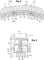
- the annular support 140 comprises hooking means 150 defining at least partly an annular groove opening radially outwards and in which is engaged the inner periphery of a radial partition 138 of a distributor sector. which is festooned or crenellated.
- the support 140 is mounted and disassembled from the inner periphery of the partition 138 in a simple and fast manner, as will be described in more detail in the following, which facilitates the replacement of the abradable elements 136 when worn.
- each distributor sector 112 comprises solid portions 154 alternating with hollow portions 156, the solid portions 154 being evenly distributed around the axis of the distributor.
- each solid portion 154 is located at the circumferential end portions of the manifold sectors 112.
- Each solid portion 154 includes a half-portion formed on one end of a partition sector 138 of a sector. of a dispenser, and a complementary half-portion formed on the end of a partition sector of an adjacent dispenser sector.
- the partition 138 of each sector thus comprises here a single hollow portion 156 which extends over a median portion of this partition.
- the solid portions 154 may have a circumferential angular size or extent of about 10 to 30% of that of a dispenser sector 112.
- each distributor sector also carries annular deflectors 142 of the aforementioned type which are fixed by brazing or welding on at least one of the lateral faces of the partition 138. These deflectors 142 are located radially outside the hollow portions 156. so as not to interfere with the mounting of the support 140 on the partition 138 ( figure 6 ).
- the support 140 has in the example shown ( figure 5 ) has a substantially C-shaped section and has a radial annular wall 168 connected to its inner and outer peripheries to inner cylindrical walls 170 and outer 172, respectively.
- the elements 136 of abradable material are fixed on the inner cylindrical surface of the wall 170 of the support 140, and the attachment means 150 are fixed on the outer cylindrical surface of the wall 170 of the support.
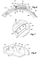
- the hooking means have a substantially L-shaped section and are made by folded sheets. They each comprise two wings 158, 160 ( Figures 7 and 8 ).
- a first flange 158 is of generally cylindrical shape centered on the axis of the support 140 and is applied and fixed, for example by welding, on the outer surface of the wall 170 of this support 140.
- the second flange 160 extends radially towards the outside from its end connected to the first flange 158, substantially parallel to the annular rim 174 of the support ( figure 5 ).
- the hooking means 150 define portions of an annular groove in which the solid parts 154 of the partitions 138 are received. Each portion is open at one circumferential end and closed at its opposite circumferential end. This closed end is obtained in the example shown by folding a circumferential end of the first flange 158 so as to form a radial flange 162 forming a stop in the circumferential direction. This stop is intended to hold the support 140 in a circumferential direction on the dispenser by circumferentially supporting the flange 162 on a full portion 154 adjacent to the partition 138.
- the second flange 160 has its circumferential end opposite the flange 162 which is also folded on the opposite side of the support 140 to form a rim 164 for guiding the support when it is mounted on the partitions 138.
- This second flange 160 further includes bosses 166 which are formed projecting on the face of this flange located substantially opposite the annular flange 174 of the support 140. These bosses 166 are formed by plastic deformation of the second flange 160 in the example represent. They make it possible to maintain axially tight the solid portions 154 of the partitions which are interposed between the flange 174 of the annular support 140 and the second flanges 160 of the attachment means ( figure 5 ), so as to limit the vibrations of the support 140 in operation.
- the radially outer faces of the first flanges 158 of the attachment means 150 may bear radially on the radially inner ends of the solid portions 154 of the partitions to ensure the centering of the support 140 vis-à-vis the distributor.
- the attachment means 150 have a circumferential dimension or angular extent which is, for example, equal to, and preferably greater than, that of the solid parts 154 of the partitions of the distributor sectors, and which is smaller than that of the hollow parts 156 of the distributor sectors. these partitions.
- the radially outer ends of the second wings 160 of the attachment means 150 define a diameter which is slightly smaller than that defined by the bottoms of the hollow portions 156 of the partitions and to that defined by the radially internal surfaces of the deflectors 142 ( figure 4 ). In this way, the attachment means 150 can be engaged in the hollow portions 156 of the partitions 138 of the distributor sectors when the support 140 is aligned axially with the distributor 112 and is brought into axial translation on the distributor.
- the hollow portions 156 have a dimension or angular extent in the circumferential direction which is for example greater than that of the solid portions 154.
- the annular support 140 is hooked onto the manifold sectors 112 as follows.
- the distributor sectors 112 are arranged circumferentially end to end.
- the support 140 is aligned coaxially with the sectorized distributor 112 and the fastening means 150 of the support are axially aligned with the hollow portions 156 of the partition 138 of the distributor 112.
- the support 140 is then moved in axial translation towards the dispenser until the annular rim 174 of the support bears axially against the annular partitions 138 of the distributor.
- the attachment means 150 are located at the hollow portions 156 of the partition and are substantially aligned in the circumferential direction with the solid portions 154 of the partition.
- the support 140 is then rotated in a direction circumferentially with respect to the dispenser until the solid portions 154 of the inner periphery of the partitions 138 penetrate into the attachment means 150.
- the solid portions 154 slide in the circumferential direction on the flanges 164 which guide them in the attachment means 150.
- the support 140 slides circumferentially on the partitions until the solid portions 154 of the partitions 138 abut on the flanges 162 of the attachment means 150.
Landscapes
- Engineering & Computer Science (AREA)
- Mechanical Engineering (AREA)
- General Engineering & Computer Science (AREA)
- Turbine Rotor Nozzle Sealing (AREA)
Description
- La présente invention concerne un distributeur de turbine pour une turbomachine telle qu'un turboréacteur ou un turbopropulseur d'avion.
- Le document
EP-A-0 017 534 décrit une garniture d'étanchéité amovible pour segment de distributeur de turbomachine. Le documentGB2022720 - Une turbomachine comprend des étages de turbine comportant chacun une roue de rotor à aubes et un distributeur, chaque distributeur étant sectorisé, c'est-à-dire formé de plusieurs secteurs de distributeur disposés circonférentiellement bout à bout.
- Chaque distributeur comporte deux plates-formes annulaires coaxiales s'étendant l'une à l'intérieur de l'autre et reliées entre elles par des pales sensiblement radiales. La plate-forme externe comporte des moyens d'accrochage sur un carter externe de la turbine et la plate-forme interne est reliée à une cloison annulaire sensiblement radiale qui porte des éléments en matériau abradable, situés radialement à l'intérieur de la plate-forme interne du distributeur. Les éléments en matériau abradable coopèrent avec des léchettes annulaires portées par le rotor de la turbine pour former des joints d'étanchéité du type à labyrinthe.
- Lorsque les éléments en matériau abradable sont usés, il est nécessaire de les remplacer par des neufs lors d'une opération de maintenance. Dans la technique actuelle, ces éléments sont fixés par brasage sur la cloison annulaire de la plate-forme interne du distributeur. Le remplacement des éléments en matériau abradable nécessite un démontage complet des secteurs du distributeur, un usinage de chaque secteur de distributeur pour enlever les éléments abradables usés, et le brasage d'éléments abradables neufs sur la cloison annulaire. Il est ensuite nécessaire de déposer un revêtement anti-oxydation sur chaque secteur de distributeur. Cette opération de remplacement des éléments abradables d'un distributeur est donc longue et coûteuse.
- Par ailleurs, les secteurs d'un distributeur sont séparés les uns des autres par de faibles jeux en direction circonférentielle pour autoriser des dilatations thermiques de leurs plates-formes en fonctionnement. Ils sont de plus soumis en fonctionnement à des vibrations et à des sollicitations dynamiques relativement importantes qui peuvent entraîner des déplacements parasites et des déformations de ces secteurs.
- On a déjà proposé de rigidifier le distributeur à l'aide de moyens d'appui axial formés sur les secteurs de plate-forme interne du distributeur, les moyens d'appui d'un secteur de plate-forme étant destinés à coopérer avec des moyens correspondants formés sur des secteurs de plate-forme interne adjacents pour limiter les déformations du distributeur en fonctionnement.
- Dans la technique actuelle, ces moyens d'appui comportent un matériau très dur appelé « stellite » qui est déposé par un procédé de soudage laser (« stellitage ») long, coûteux, difficile à mettre en oeuvre, et qui risque de détériorer les secteurs de distributeur. Cette technologie n'est en outre pas réalisable sur certains distributeurs dont les plates-formes ont des formes trop complexes (appelées plates-formes 3D).
- La présente invention a notamment pour but d'apporter une solution simple, efficace et économique aux problèmes de la technique antérieure, en simplifiant le remplacement des éléments en matériau abradable du distributeur, et en supprimant le stellitage des secteurs de ce distributeur.
- Elle propose à cet effet un distributeur de turbine pour une turbomachine, ce distributeur étant sectorisé et formé de secteurs disposés bout à bout, et chaque secteur comprenant deux plates-formes annulaires coaxiales, respectivement interne et externe, reliées entre elles par des pales sensiblement radiales, la plate-forme interne étant reliée à une cloison annulaire sensiblement radiale, caractérisé en ce que la périphérie interne de la cloison annulaire de chaque secteur est festonnée ou crénelée et comprend des parties pleines en alternance avec des parties creuses, et en ce que des éléments en matériau abradable sont fixés sur un support annulaire continu qui comprend des moyens d'accrochage sur les cloisons annulaires des secteurs, le support pouvant coulisser circonférentiellement sur les cloisons et étant déplaçable angulairement entre une position de montage et de démontage et une position de blocage dans laquelle les moyens d'accrochage coopèrent avec les parties pleines des cloisons annulaires des secteurs pour assurer le maintien du support sur cette cloison.
- Au contraire de la technique antérieure, le support des éléments abradables est selon l'invention monté de manière amovible sur la cloison, ce qui facilite le remplacement des éléments abradables usés. Il suffit en effet de faire tourner le support annulaire sur les cloisons des secteurs et de remplacer ce support par un nouveau support portant des éléments abradables neufs. Le remontage du support sur les cloisons des secteurs de distributeur est en outre simple et rapide car il peut s'effectuer sur un ensemble de distributeurs déjà en place dans la turbomachine.
- L'invention permet également de simplifier la fabrication de chaque secteur de distributeur qui est obtenu de fonderie, car le support des abradables est désormais réalisé indépendamment de ces secteurs.
- La cloison du distributeur est en outre allégée grâce à sa forme festonnée ou crénelée.
- Le support annulaire n'est pas sectorisé et s'étend circonférentiellement sur tous les secteurs de distributeur, ce qui permet de rigidifier les secteurs de distributeur et de limiter leurs vibrations et leurs déplacements parasites en fonctionnement, tout en autorisant leurs dilatations circonférentielles. Il n'est donc plus nécessaire de déposer par stellitage un matériau dur sur les moyens d'appui axial des secteurs de distributeur, ce qui permet de faire l'économie de cette opération longue et coûteuse, et de supprimer le risque de détérioration des secteurs de distributeur lors de cette opération délicate.
- Selon une autre caractéristique de l'invention, le support est en forme de rail et est réalisé en tôle, ce qui permet notamment d'alléger le distributeur de façon significative par rapport à la technique antérieure.
- Les moyens d'accrochage peuvent définir des portions d'une gorge annulaire débouchant radialement vers l'extérieur et dans lesquelles sont logées les parties pleines des cloisons des secteurs de distributeur en position de blocage. Chacune de ces portions de gorge annulaire comprend avantageusement une extrémité circonférentielle ouverte pour l'engagement des moyens d'accrochage sur au moins une partie pleine d'une cloison d'un secteur de distributeur, et une extrémité circonférentielle opposée fermée de blocage en rotation dans un sens du support sur la cloison. Les moyens d'accrochage peuvent avoir en section une forme sensiblement en L ou en U, et être régulièrement répartis sur une circonférence du support. En position de montage, chaque cloison est de préférence maintenue serrée par les moyens d'accrochage de façon à limiter les vibrations du support en fonctionnement.
- Les moyens d'accrochage sont de préférence réalisés en tôle et sont rapportés et fixés, par exemple par brasage ou soudage, sur le support annulaire. Les moyens d'accrochage sont par exemple formés par des tôles pliées.
- Le nombre de parties pleines de la cloison est par exemple égal au nombre de secteurs de distributeur. Les parties pleines peuvent être formées aux extrémités circonférentielles des cloisons des secteurs de distributeur. La cloison de chaque secteur peut comprendre à chacune de ses extrémités circonférentielles une portion de partie pleine dont l'autre portion est formée sur une extrémité circonférentielle de la cloison d'un secteur de distributeur adjacent. Les parties pleines peuvent avoir une dimension ou un étendue angulaire en direction circonférentielle qui est inférieure ou égale à celle des parties creuses. Les moyens d'accrochage peuvent en outre avoir une dimension ou une étendue angulaire en direction circonférentielle qui est égale ou supérieure à celle des parties pleines des cloisons des secteurs.
- Des déflecteurs annulaires en tôle peuvent en outre être fixés, par exemple par brasage, sur les cloisons des secteurs de distributeur. Ces déflecteurs annulaires sont destinés à coopérer avec des éléments correspondants des roues de rotor situées en amont et en aval du distributeur pour limiter le passage d'air en direction radiale entre le distributeur et ces roues de rotor.
- L'invention concerne également des secteurs de distributeur pour un distributeur du type précité, comprenant deux plates-formes annulaires coaxiales, respectivement interne et externe, reliées entre elles par des pales sensiblement radiales, la plate-forme interne étant solidaire d'une cloison annulaire radialement interne, caractérisé en ce que la périphérie interne de la cloison est festonnée ou crénelée et comprend des parties pleines en alternance avec des parties creuses.
- L'invention concerne encore un support annulaire continu pour un distributeur tel que décrit ci-dessus, caractérisé en ce qu'il comprend des moyens d'accrochage régulièrement répartis autour de l'axe du support et définissant des portions d'une gorge annulaire.
- L'invention concerne en outre une turbine basse-pression de turbomachine, comprenant au moins un distributeur du type précité, ainsi qu'une turbomachine, telle qu'un turboréacteur ou un turbopropulseur d'avion, comprenant au moins un distributeur tel que décrit ci-dessus.
- L'invention sera mieux comprise et d'autres détails, caractéristiques et avantages de la présente invention apparaîtront plus clairement à la lecture de la description qui suit faite à titre d'exemple non limitatif et en référence aux dessins annexés, dans lesquels :
- la
figure 1 est une demi-vue schématique en coupe axiale d'une turbine basse-pression de turbomachine, - la
figure 2 est une vue schématique partielle en perspective d'un secteur de distributeur, selon la technique antérieure à l'invention, - la
figure 3 est une vue schématique en perspective des moyens d'appui axial entre deux secteurs de distributeur adjacents de la technique antérieure, - la
figure 4 est une vue schématique partielle en perspective d'un distributeur selon l'invention, - la
figure 5 est une vue en coupe selon la ligne V-V de lafigure 4 , à plus grande échelle, - la
figure 6 est une vue schématique partielle en perspective d'un secteur de distributeur et d'un support d'abradables selon l'invention, - la
figure 7 est une vue à plus grande échelle d'une partie de lafigure 6 et représente des moyens d'accrochage du support d'abradables selon l'invention, et - la
figure 8 est une vue schématique en perspective des moyens d'accrochage de lafigure 6 . - On se réfère d'abord à la
figure 1 qui représente une turbine basse-pression 10 de turbomachine comprenant quatre étages comportant chacun un distributeur 12 porté par un carter externe 16 de la turbine et une roue à aubes 18 située en aval du distributeur 12. - Les roues 18 comprennent des disques 20 assemblés coaxialement par des brides annulaires 22 et portant des aubes 24 sensiblement radiales. Ces roues 18 sont reliées à un arbre de turbine (non représenté) par l'intermédiaire d'un cône d'entraînement 26 fixé sur des brides annulaires 22 des disques.
- Des flasques annulaires 28 de retenue axiale des aubes 24 sur les disques 20 sont montés entre les disques et comprennent chacun une paroi radiale interne 29 serrée axialement entre les brides annulaires 22 de deux disques adjacents.
- Les distributeurs 12 comprennent chacun deux plates-formes annulaires 30, 32 coaxiales, respectivement interne et externe, qui délimitent entre elles la veine annulaire d'écoulement des gaz dans la turbine et entre lesquelles s'étendent des pales fixes 14 sensiblement radiales. Les plates-formes externes 32 des distributeurs sont accrochées par des moyens appropriés sur le carter externe 16 de la turbine.
- La plate-forme interne 30 de chaque distributeur est solidaire d'une cloison annulaire 38 radialement interne portant des éléments annulaires 36 en matériau abradable, ces éléments 36 étant agencés sur une surface cylindrique de la cloison annulaire 38. Dans l'exemple représenté, la cloison annulaire 38 est sensiblement radiale et sa périphérie externe est reliée à la surface interne de la plate-forme interne 30 du distributeur. Les éléments abradables 36 sont fixés sur la périphérie cylindrique interne de la cloison annulaire 38.
- Les éléments abradables 36 sont agencés radialement à l'extérieur et en regard de léchettes annulaires externes 42 portées par les flasques 28. Les léchettes 42 sont destinées à coopérer par frottement avec les éléments 36 de façon à former des joints à labyrinthe et à limiter le passage de gaz en direction axiale à travers ces joints.
- Les distributeurs 12 de la turbine sont sectorisés et sont chacun formés de plusieurs secteurs disposés circonférentiellement bout à bout autour de l'axe longitudinal de la turbine.
- On a représenté en
figure 2 une partie d'un secteur de distributeur 12 selon la technique antérieure à la présente invention. Ce secteur de distributeur 12 comprend un secteur de plate-forme interne 30 et un secteur de plate-forme externe (non visible) reliés entre eux par sept pales 14. Le secteur de plate-forme interne 30 est solidaire d'un secteur de cloison 38 portant des éléments abradables 36. Le secteur de plate-forme 30 et le secteur de cloison 38 sont formés d'une seule pièce de fonderie. - Dans la technique actuelle, les éléments abradables 36 sont fixés par brasage sur la périphérie interne du secteur de cloison 38. Des déflecteurs annulaires 42 en tôle sont en outre fixés par brasage sur la périphérie interne du secteur de cloison 38, en amont et en aval des éléments abradables 36. Ces déflecteurs 42 coopèrent par effet de chicane avec des moyens correspondants des roues à aubes 18 situées en mont et en aval du distributeur pour limiter le passage de gaz en direction radiale entre le distributeur et ces roues à aubes.
- Le remplacement des éléments abradables 36 est dans ce cas une opération longue et coûteuse, comme cela a été indiqué dans ce qui précède.
- Les bords longitudinaux 44, 44' du secteur de plate-forme interne 30 de chaque secteur de distributeur 12 ont à leurs extrémités circonférentielles des formes complémentaires des bords longitudinaux correspondants des secteurs de plates-formes internes des secteurs de distributeur adjacents, de façon à ce que les extrémités des bords longitudinaux s'encastrent circonférentiellement les unes dans les autres au montage de ce distributeur (
figure 3 ). - Dans la technique actuelle, les extrémités des bords longitudinaux 44, 44' des secteurs de plate-forme interne 30 sont usinées en Z pour définir des moyens 46 d'appui axial entre les secteurs de distributeur 12. L'appui axial d'un secteur de plate-forme interne 30 sur un secteur de plate-forme interne adjacent permet de limiter les déplacements parasites et les vibrations des secteurs de distributeur 12 en fonctionnement de la turbine.
- Les moyens d'appui 46 comportent un matériau dur appelé « stellite » déposé par un procédé long, coûteux, et difficile à mettre en oeuvre, comme cela a également été décrit dans ce qui précède.
- L'invention permet de remédier au moins en partie aux problèmes indiqués ci-dessus grâce à un support annulaire 140 non sectorisé qui est accroché de manière amovible sur la cloison annulaire 138 du distributeur et qui porte les éléments 136 en matériau abradable.
- Dans l'exemple de réalisation représenté aux
figures 4 à 8 , le support annulaire 140 est en forme de rail et est réalisé en tôle, par exemple en tôle emboutie. - Le support 140 s'étend sur 360° et permet de rigidifier l'ensemble des secteurs de distributeur 112 dont les extrémités circonférentielles peuvent être dépourvues de stellite. Les extrémités des bords longitudinaux 144, 144' des secteurs de plate-forme interne de chaque distributeur peuvent être conformées en Z, comme dans la technique antérieure, pour conserver les surfaces d'appui axial, ou bien être en coupe droite pour supprimer ces surfaces d'appui axial.
- Selon la présente invention, le support annulaire 140 comporte des moyens d'accrochage 150 définissant au moins en partie une gorge annulaire débouchant radialement vers l'extérieur et dans laquelle est engagée la périphérie interne d'une cloison radiale 138 d'un secteur de distributeur, qui est festonnée ou crénelée. Le support 140 est monté et démonté de la périphérie interne de la cloison 138 de façon simple et rapide, comme cela sera décrit plus en détail dans ce qui suit, ce qui permet de faciliter le remplacement des éléments abradables 136 lorsqu'ils sont usés.
- La périphérie interne de la cloison 138 de chaque secteur de distributeur 112 comprend des parties pleines 154 en alternance avec des parties creuses 156, les parties pleines 154 étant régulièrement réparties autour de l'axe du distributeur.
- Dans l'exemple représenté, les parties pleines 154 sont situées au niveau des parties d'extrémité circonférentielle des secteurs de distributeur 112. Chaque partie pleine 154 comprend une demi-portion formée sur une extrémité d'un secteur de cloison 138 d'un secteur de distributeur, et une demi-portion complémentaire formée sur l'extrémité d'un secteur de cloison d'un secteur de distributeur adjacent. La cloison 138 de chaque secteur comporte donc ici une seule partie creuse 156 qui s'étend sur une partie médiane de cette cloison.
- Les parties pleines 154 peuvent avoir une dimension ou une étendue angulaire en direction circonférentielle représentant environ 10 à 30% de celle d'un secteur de distributeur 112.
- La cloison de chaque secteur de distributeur porte en outre des déflecteurs annulaires 142 du type précité qui sont fixés par brasage ou soudage sur au moins une des faces latérales de la cloison 138. Ces déflecteurs 142 sont situés radialement à l'extérieur des parties creuses 156 pour ne pas gêner le montage du support 140 sur la cloison 138 (
figure 6 ). - Le support 140 a dans l'exemple représenté (
figure 5 ) une forme sensiblement en C en section et comporte une paroi annulaire radiale 168 reliée à ses périphéries interne et externe à des parois cylindriques interne 170 et externe 172, respectivement. La partie d'extrémité axiale de la paroi cylindrique externe 172, située du côté opposé à la paroi radiale, est pliée vers l'intérieur de façon à former un rebord annulaire radial 174 s'étendant vers l'intérieur depuis la paroi externe 172. - Les éléments 136 en matériau abradable sont fixés sur la surface cylindrique interne de la paroi 170 du support 140, et les moyens d'accrochage 150 sont fixés sur la surface cylindrique externe de cette paroi 170 du support.
- Dans l'exemple représenté, les moyens d'accrochage ont en section une forme sensiblement en L et sont réalisés par des tôles pliées. Ils comprennent chacun deux ailes 158, 160 (
figures 7 et 8 ). - Une première aile 158 est de forme générale cylindrique centrée sur l'axe du support 140 et est appliquée et fixée, par exemple par soudage, sur la surface externe de la paroi 170 de ce support 140. La seconde aile 160 s'étend radialement vers l'extérieur depuis son extrémité reliée à la première aile 158, sensiblement parallèlement au rebord annulaire 174 du support (
figure 5 ). - Les moyens d'accrochage 150 définissent des portions d'une gorge annulaire dans lesquelles sont reçues les parties pleines 154 des cloisons 138. Chaque portion est ouverte à une extrémité circonférentielle et fermée à son extrémité circonférentielle opposée. Cette extrémité fermée est obtenue dans l'exemple représenté par pliage d'une extrémité circonférentielle de la première aile 158 de façon à former un rebord radial 162 formant butée en direction circonférentielle. Cette butée est destinée à retenir le support 140 dans un sens en direction circonférentielle sur le distributeur par appui circonférentiel du rebord 162 sur une partie pleine 154 adjacente de la cloison 138.
- La seconde aile 160 a son extrémité circonférentielle opposée au rebord 162 qui est également pliée du côté opposé au support 140 pour former un rebord 164 de guidage du support lors de son montage sur les cloisons 138.
- Cette seconde aile 160 comporte en outre des bossages 166 qui sont formés en saillie sur la face de cette aile située sensiblement en regard du rebord annulaire 174 du support 140. Ces bossages 166 sont formés par déformation plastique de la seconde aile 160 dans l'exemple représenté. Ils permettent de maintenir axialement serrées les parties pleines 154 des cloisons qui sont intercalées entre le rebord 174 du support annulaire 140 et les secondes ailes 160 des moyens d'accrochage (
figure 5 ), de façon à limiter les vibrations du support 140 en fonctionnement. - Les faces radialement externes des premières ailes 158 des moyens d'accrochage 150 peuvent venir en appui radial sur les extrémités radialement internes des parties pleines 154 des cloisons pour assurer le centrage du support 140 vis-à-vis du distributeur.
- Les moyens d'accrochage 150 ont une dimension ou étendue angulaire en direction circonférentielle qui est par exemple égale, et de préférence supérieure, à celle des parties pleines 154 des cloisons des secteurs de distributeur, et qui est inférieure à celle des parties creuses 156 de ces cloisons. Les extrémités radialement externes des secondes ailes 160 des moyens d'accrochage 150 définissent un diamètre qui est légèrement inférieur à celui défini par les fonds des parties creuses 156 des cloisons et à celui défini par les surfaces radialement internes des déflecteurs 142 (
figure 4 ). De cette façon, les moyens d'accrochage 150 peuvent être engagés dans les parties creuses 156 des cloisons 138 des secteurs de distributeur lorsque le support 140 est aligné axialement avec le distributeur 112 et est amené en translation axiale sur le distributeur. Les parties creuses 156 ont une dimension ou étendue angulaire en direction circonférentielle qui est par exemple supérieure à celle des parties pleines 154. - Le support annulaire 140 est accroché sur les secteurs de distributeur 112 de la façon suivante. Les secteurs de distributeur 112 sont disposés circonférentiellement bout à bout. Le support 140 est aligné coaxialement avec le distributeur sectorisé 112 et les moyens d'accrochage 150 du support sont alignés axialement avec les parties creuses 156 de la cloison 138 du distributeur 112. Le support 140 est ensuite déplacé en translation axiale vers le distributeur jusqu'à ce que le rebord annulaire 174 du support soit en appui axial contre les cloisons annulaires 138 du distributeur. Dans cette position, appelée position de montage et de démontage, les moyens d'accrochage 150 sont situés au niveau des parties creuses 156 de la cloison et sont sensiblement alignés en direction circonférentielle avec les parties pleines 154 de cette cloison. Le support 140 est alors tourné dans un sens en direction circonférentielle par rapport au distributeur jusqu'à ce que les parties pleines 154 de la périphérie interne des cloisons 138 pénètrent dans les moyens d'accrochage 150. Les parties pleines 154 glissent en direction circonférentielle sur les rebords 164 qui les guident dans les moyens d'accrochage 150. Le support 140 glisse circonférentiellement sur les cloisons jusqu'à ce que les parties pleines 154 des cloisons 138 viennent en butée sur les rebords 162 des moyens d'accrochage 150. Les opérations précitées sont réalisées en ordre contraire pour le démontage du distributeur, et pour le remplacement du support 140 ou des éléments abradables 136 de ce support.
Claims (12)
- Distributeur (112) de turbine pour une turbomachine, ce distributeur étant sectorisé et formé de secteurs disposés bout à bout, et chaque secteur comprenant deux plates-formes annulaires coaxiales, respectivement interne (130) et externe, reliées entre elles par des pales (114) sensiblement radiales, la plate-forme interne étant reliée à une cloison annulaire (138) sensiblement radiale, la périphérie interne de la cloison annulaire de chaque secteur étant festonnée ou crénelée et comprenant des parties pleines (154) en alternance avec des parties creuses (156), le distributeur comprenant des éléments en matériau abradable et un support annulaire, les éléments en matériau abradable étant fixés sur le support annulaire (140), caractérisé en ce que le support annulaire s'étend en continu sur 360°, et comprend des moyens (150) d'accrochage sur les cloisons annulaires des secteurs, le support annulaire étant configuré pour coulisser circonférentiellement sur les cloisons et pour être déplaçable angulairement entre une position de montage et de démontage et une position de blocage dans laquelle les moyens d'accrochage coopèrent avec les parties pleines des cloisons annulaires des secteurs pour assurer le maintien du support sur cette cloison.
- Distributeur selon la revendication 1, caractérisé en ce que le support (140) est en forme de rail et est réalisé en tôle.
- Distributeur selon la revendication 1 ou 2, caractérisé en ce que les moyens d'accrochage (150) définissent des portions d'une gorge annulaire débouchant radialement vers l'extérieur et dans lesquelles sont logées les parties pleines (154) des cloisons annulaires des secteurs en position de blocage.
- Distributeur selon la revendication 3, caractérisé en ce que chaque portion de gorge annulaire comprend une extrémité circonférentielle ouverte pour l'engagement des moyens d'accrochage sur au moins une partie pleine (154) de la cloison, et une extrémité circonférentielle opposée fermée de blocage en rotation dans un sens du support sur la cloison.
- Distributeur selon l'une des revendications précédentes, caractérisé en ce que les moyens d'accrochage (150) ont en section une forme sensiblement en L ou en U et sont régulièrement répartis sur une circonférence du support.
- Distributeur selon l'une des revendications précédentes, caractérisé en ce que les moyens d'accrochage (150) sont réalisés en tôle et sont rapportés et fixés, par exemple par brasage ou soudage, sur le support annulaire (140).
- Distributeur selon l'une des revendications précédentes, caractérisé en ce que les parties pleines (154) sont formées aux extrémités circonférentielles des cloisons (138) des secteurs de distributeur (112).
- Distributeur selon la revendication 7, caractérisé en ce que la cloison de chaque secteur comprend à chacune de ses extrémités circonférentielles une portion de partie pleine dont l'autre portion est formée sur une extrémité circonférentielle de la cloison d'un secteur de distributeur adjacent.
- Distributeur selon l'une des revendications précédentes, caractérisé en ce que les moyens d'accrochage (150) ont une dimension ou une étendue angulaire en direction circonférentielle qui est égale ou supérieure à celle des parties pleines des cloisons des secteurs.
- Distributeur selon l'une des revendications précédentes, caractérisé en ce que des déflecteurs annulaires (142) en tôle sont fixés, par exemple par brasage, sur la cloison.
- Turbine basse-pression de turbomachine, caractérisée en ce qu'elle comprend au moins un distributeur (112) selon l'une des revendications 1 à 10.
- Turbomachine, telle qu'un turboréacteur ou un turbopropulseur d'avion, caractérisée en ce qu'elle comprend au moins un distributeur (112) selon l'une des revendications 1 à 10.
Applications Claiming Priority (2)
| Application Number | Priority Date | Filing Date | Title |
|---|---|---|---|
| FR0802293A FR2930592B1 (fr) | 2008-04-24 | 2008-04-24 | Distributeur de turbine pour une turbomachine |
| PCT/FR2009/000457 WO2009136016A1 (fr) | 2008-04-24 | 2009-04-17 | Distributeur de turbine pour une turbomachine |
Publications (2)
| Publication Number | Publication Date |
|---|---|
| EP2271828A1 EP2271828A1 (fr) | 2011-01-12 |
| EP2271828B1 true EP2271828B1 (fr) | 2019-08-21 |
Family
ID=40342442
Family Applications (1)
| Application Number | Title | Priority Date | Filing Date |
|---|---|---|---|
| EP09742214.1A Active EP2271828B1 (fr) | 2008-04-24 | 2009-04-17 | Distributeur de turbine pour une turbomachine |
Country Status (10)
| Country | Link |
|---|---|
| US (1) | US9322286B2 (fr) |
| EP (1) | EP2271828B1 (fr) |
| JP (1) | JP5547714B2 (fr) |
| CN (1) | CN102016236B (fr) |
| BR (1) | BRPI0910756B8 (fr) |
| CA (1) | CA2721215C (fr) |
| ES (1) | ES2746200T3 (fr) |
| FR (1) | FR2930592B1 (fr) |
| RU (1) | RU2532868C2 (fr) |
| WO (1) | WO2009136016A1 (fr) |
Families Citing this family (21)
| Publication number | Priority date | Publication date | Assignee | Title |
|---|---|---|---|---|
| FR2925107B1 (fr) * | 2007-12-14 | 2010-01-22 | Snecma | Distributeur sectorise pour une turbomachine |
| FR2971022B1 (fr) * | 2011-02-02 | 2013-01-04 | Snecma | Etage redresseur de compresseur pour une turbomachine |
| FR2977274B1 (fr) * | 2011-06-30 | 2013-07-12 | Snecma | Joint d'etancheite a labyrinthe pour turbine d'un moteur a turbine a gaz |
| JP5946543B2 (ja) * | 2011-12-23 | 2016-07-06 | ゲーコーエヌ エアロスペース スウェーデン アーベー | ガスタービンエンジンの支持構造物 |
| ITTO20121012A1 (it) * | 2012-11-21 | 2014-05-22 | Avio Spa | Assieme statore-rotore di una turbina a gas per motori aeronautici |
| FR3001252B1 (fr) * | 2013-01-23 | 2015-02-13 | Snecma | Aubage fixe de distribution de flux comprenant une plate-forme interne a renforts integres |
| FR3003599B1 (fr) * | 2013-03-25 | 2017-11-17 | Snecma | Aubage fixe de distribution de flux ameliore |
| FR3036433B1 (fr) * | 2015-05-22 | 2019-09-13 | Safran Ceramics | Ensemble d'anneau de turbine avec maintien par crabotage |
| FR3041374B1 (fr) * | 2015-09-17 | 2020-05-22 | Safran Aircraft Engines | Secteur de distributeur pour turbomachine avec des aubes refroidies de maniere differentielle |
| EP3409897B1 (fr) | 2017-05-29 | 2019-12-18 | MTU Aero Engines GmbH | Agencement d'étanchéité pour une turbomachine, méthode de fabrication de l'agencement d'étanchéité et turbomachine |
| US10724389B2 (en) * | 2017-07-10 | 2020-07-28 | Raytheon Technologies Corporation | Stator vane assembly for a gas turbine engine |
| US10774668B2 (en) * | 2017-09-20 | 2020-09-15 | General Electric Company | Intersage seal assembly for counter rotating turbine |
| FR3073003B1 (fr) * | 2017-10-31 | 2019-10-11 | Safran Aircraft Engines | Capuchon amovible anti-usure pour secteur de redresseur |
| US10544699B2 (en) * | 2017-12-19 | 2020-01-28 | Rolls-Royce Corporation | System and method for minimizing the turbine blade to vane platform overlap gap |
| FR3085991B1 (fr) * | 2018-09-14 | 2020-09-18 | Safran Aircraft Engines | Element de turbomachine d'aeronef et son procede de controle |
| US11028709B2 (en) * | 2018-09-18 | 2021-06-08 | General Electric Company | Airfoil shroud assembly using tenon with externally threaded stud and nut |
| FR3091311B1 (fr) * | 2018-12-31 | 2021-04-09 | Safran Aircraft Engines | Distributeur pour turbine, turbine de turbomachine équipée de ce distributeur et turbomachine équipée de cette turbine. |
| FR3117532B1 (fr) * | 2020-12-10 | 2024-05-24 | Safran Aircraft Engines | Aube de turbine pour turbomachine d’aéronef, pourvue d’un canal d’éjection de flux primaire vers une cavité inter-léchettes |
| US11428160B2 (en) | 2020-12-31 | 2022-08-30 | General Electric Company | Gas turbine engine with interdigitated turbine and gear assembly |
| FR3133063B1 (fr) * | 2022-02-25 | 2024-08-02 | Safran Aircraft Engines | Aubage de turbomachine, comprenant une pale et une plateforme qui présente un canal interne d’aspiration et d’éjection de flux |
| CN118896009B (zh) * | 2024-07-30 | 2025-11-18 | 中国航发沈阳发动机研究所 | 一种抑制低导外环块脱出结构 |
Family Cites Families (26)
| Publication number | Priority date | Publication date | Assignee | Title |
|---|---|---|---|---|
| US2812159A (en) * | 1952-08-19 | 1957-11-05 | Gen Electric | Securing means for turbo-machine blading |
| US3079128A (en) * | 1961-01-23 | 1963-02-26 | Burge Joseph | Sealing and securing means for turbomachine blading |
| US4139376A (en) * | 1974-02-28 | 1979-02-13 | Brunswick Corporation | Abradable seal material and composition thereof |
| US4094673A (en) * | 1974-02-28 | 1978-06-13 | Brunswick Corporation | Abradable seal material and composition thereof |
| FR2427469A1 (fr) * | 1978-06-01 | 1979-12-28 | Snecma | Dispositif de fixation d'une garniture d'etancheite sur un distributeur de turbomachine |
| FR2452590A1 (fr) * | 1979-03-27 | 1980-10-24 | Snecma | Garniture d'etancheite amovible pour segment de distributeur de turbomachine |
| DE3003469C2 (de) * | 1980-01-31 | 1987-03-19 | MTU Motoren- und Turbinen-Union München GmbH, 8000 München | Einrichtung zur Verbindung einander rotationssymmetrisch zugeordneter, unterschiedlichen thermischen Einflüssen ausgesetzter Bauteile für Strömungsmaschinen, insbesondere Gasturbinentriebwerke |
| FR2552159B1 (fr) * | 1983-09-21 | 1987-07-10 | Snecma | Dispositif de liaison et d'etancheite de secteurs d'aubes de stator de turbine |
| FR2556410B1 (fr) * | 1983-12-07 | 1986-09-12 | Snecma | Dispositif de centrage de l'anneau interieur d'un stator a ailettes a calage variable |
| US4645424A (en) * | 1984-07-23 | 1987-02-24 | United Technologies Corporation | Rotating seal for gas turbine engine |
| US4710097A (en) * | 1986-05-27 | 1987-12-01 | Avco Corporation | Stator assembly for gas turbine engine |
| US4767267A (en) * | 1986-12-03 | 1988-08-30 | General Electric Company | Seal assembly |
| US4820119A (en) * | 1988-05-23 | 1989-04-11 | United Technologies Corporation | Inner turbine seal |
| US4897021A (en) * | 1988-06-02 | 1990-01-30 | United Technologies Corporation | Stator vane asssembly for an axial flow rotary machine |
| US5215435A (en) * | 1991-10-28 | 1993-06-01 | General Electric Company | Angled cooling air bypass slots in honeycomb seals |
| GB9304994D0 (en) * | 1993-03-11 | 1993-04-28 | Rolls Royce Plc | Improvements in or relating to gas turbine engines |
| US5346362A (en) * | 1993-04-26 | 1994-09-13 | United Technologies Corporation | Mechanical damper |
| US6042334A (en) * | 1998-08-17 | 2000-03-28 | General Electric Company | Compressor interstage seal |
| US6139264A (en) * | 1998-12-07 | 2000-10-31 | General Electric Company | Compressor interstage seal |
| ITMI991208A1 (it) * | 1999-05-31 | 2000-12-01 | Nuovo Pignone Spa | Dispositivo per il posizionamento di ugelli di uno stadio statorico eper il raffreddamento di dischi rotorici in turbine a gas |
| US6220815B1 (en) * | 1999-12-17 | 2001-04-24 | General Electric Company | Inter-stage seal retainer and assembly |
| FR2835563B1 (fr) * | 2002-02-07 | 2004-04-02 | Snecma Moteurs | Agencement d'accrochage de secteurs en arc de cercle de distributeur porteur d'aubes |
| JP4200846B2 (ja) * | 2003-07-04 | 2008-12-24 | 株式会社Ihi | シュラウドセグメント |
| FR2865002B1 (fr) * | 2004-01-12 | 2006-05-05 | Snecma Moteurs | Turboreacteur a double flux comprenant un support de distribution de servitudes et le support de distribution de servitudes. |
| FR2899281B1 (fr) * | 2006-03-30 | 2012-08-10 | Snecma | Dispositif de refroidissement d'un carter de turbine d'une turbomachine |
| US7635251B2 (en) * | 2006-06-10 | 2009-12-22 | United Technologies Corporation | Stator assembly for a rotary machine |
-
2008
- 2008-04-24 FR FR0802293A patent/FR2930592B1/fr active Active
-
2009
- 2009-04-17 RU RU2010147834/06A patent/RU2532868C2/ru active
- 2009-04-17 BR BRPI0910756A patent/BRPI0910756B8/pt active IP Right Grant
- 2009-04-17 US US12/989,019 patent/US9322286B2/en active Active
- 2009-04-17 CN CN200980114352.7A patent/CN102016236B/zh active Active
- 2009-04-17 EP EP09742214.1A patent/EP2271828B1/fr active Active
- 2009-04-17 WO PCT/FR2009/000457 patent/WO2009136016A1/fr not_active Ceased
- 2009-04-17 CA CA2721215A patent/CA2721215C/fr active Active
- 2009-04-17 JP JP2011505552A patent/JP5547714B2/ja active Active
- 2009-04-17 ES ES09742214T patent/ES2746200T3/es active Active
Non-Patent Citations (1)
| Title |
|---|
| None * |
Also Published As
| Publication number | Publication date |
|---|---|
| CA2721215C (fr) | 2017-04-04 |
| JP2011518982A (ja) | 2011-06-30 |
| ES2746200T3 (es) | 2020-03-05 |
| FR2930592A1 (fr) | 2009-10-30 |
| RU2010147834A (ru) | 2012-05-27 |
| US20110044798A1 (en) | 2011-02-24 |
| WO2009136016A1 (fr) | 2009-11-12 |
| JP5547714B2 (ja) | 2014-07-16 |
| EP2271828A1 (fr) | 2011-01-12 |
| RU2532868C2 (ru) | 2014-11-10 |
| CN102016236B (zh) | 2014-06-18 |
| BRPI0910756B8 (pt) | 2021-01-26 |
| US9322286B2 (en) | 2016-04-26 |
| FR2930592B1 (fr) | 2010-04-30 |
| BRPI0910756B1 (pt) | 2020-04-28 |
| CN102016236A (zh) | 2011-04-13 |
| CA2721215A1 (fr) | 2009-11-12 |
Similar Documents
| Publication | Publication Date | Title |
|---|---|---|
| CA2721215C (fr) | Distributeur de turbine pour une turbomachine | |
| EP2252772B1 (fr) | Distributeur sectorisé pour une turbomachine | |
| EP3597864B1 (fr) | Ensemble d'étanchéité pour un rotor de turbine de turbomachine et turbine de turbomachine comprenant un tel ensemble | |
| EP2334909B1 (fr) | Etanchéité entre une chambre de combustion et un distributeur de turbine dans une turbomachine | |
| EP2839117B1 (fr) | Étage de turbine pour une turbomachine | |
| EP1975374B1 (fr) | Enveloppe externe étanche pour une roue de turbine de turbomachine | |
| CA2717983A1 (fr) | Distributeur de turbine pour une turbomachine | |
| EP2053200B1 (fr) | Contrôle du jeu en sommet d'aubes dans une turbine haute-pression de turbomachine | |
| EP2071129B1 (fr) | Distributeur sectorisé pour une turbomachine | |
| EP3049637B1 (fr) | Ensemble rotatif pour turbomachine | |
| WO2013001240A1 (fr) | Joint d'etancheite a labyrinthe pour turbine d'un moteur a turbine a gaz | |
| FR2972759A1 (fr) | Systeme d'etancheite et de retenue axiale des aubes pour une roue de turbine de turbomachine | |
| EP3591178A1 (fr) | Module d'étanchéité de turbomachine d'aeronef | |
| EP3161263A1 (fr) | Ensemble rotatif pour turbomachine | |
| EP3421730B1 (fr) | Turbine pour turbomachine avec anneau d'étanchéité comportant deux parties | |
| EP2060751B1 (fr) | Etage de turbine ou de compresseur d'un turboréacteur | |
| FR3072122B1 (fr) | Roue de turbomachine | |
| EP3880939A1 (fr) | Étanchéité entre une roue mobile et un distributeur d'une turbomachine | |
| EP2601009A1 (fr) | Procede de fabrication d'un tambour de turbomachine | |
| EP2060744B1 (fr) | Etage de turbine ou de compresseur de turbomachine | |
| FR3061741A1 (fr) | Turbine pour turbomachine | |
| FR2997128A1 (fr) | Aubage redresseur de turbomachine | |
| EP3853445B1 (fr) | Etancheite d'une turbine | |
| FR2960590A1 (fr) | Distributeur de turbine pour une turbomachine | |
| FR2989722A1 (fr) | Etage de turbine dans une turbomachine |
Legal Events
| Date | Code | Title | Description |
|---|---|---|---|
| PUAI | Public reference made under article 153(3) epc to a published international application that has entered the european phase |
Free format text: ORIGINAL CODE: 0009012 |
|
| 17P | Request for examination filed |
Effective date: 20101021 |
|
| AK | Designated contracting states |
Kind code of ref document: A1 Designated state(s): AT BE BG CH CY CZ DE DK EE ES FI FR GB GR HR HU IE IS IT LI LT LU LV MC MK MT NL NO PL PT RO SE SI SK TR |
|
| AX | Request for extension of the european patent |
Extension state: AL BA RS |
|
| RIN1 | Information on inventor provided before grant (corrected) |
Inventor name: DIGARD BROU DE CUISSART, SEBASTIEN Inventor name: RICHARD, BRUNO, MARIE, BENJAMIN, JACQUES Inventor name: MATHIEU, DAVID Inventor name: HERZER, ERIC, RENE |
|
| DAX | Request for extension of the european patent (deleted) | ||
| 17Q | First examination report despatched |
Effective date: 20120615 |
|
| STAA | Information on the status of an ep patent application or granted ep patent |
Free format text: STATUS: EXAMINATION IS IN PROGRESS |
|
| RAP1 | Party data changed (applicant data changed or rights of an application transferred) |
Owner name: SAFRAN AIRCRAFT ENGINES |
|
| RIC1 | Information provided on ipc code assigned before grant |
Ipc: F01D 11/00 20060101ALI20190207BHEP Ipc: F01D 9/04 20060101AFI20190207BHEP Ipc: F01D 25/24 20060101ALI20190207BHEP Ipc: F01D 11/02 20060101ALI20190207BHEP |
|
| GRAP | Despatch of communication of intention to grant a patent |
Free format text: ORIGINAL CODE: EPIDOSNIGR1 |
|
| STAA | Information on the status of an ep patent application or granted ep patent |
Free format text: STATUS: GRANT OF PATENT IS INTENDED |
|
| INTG | Intention to grant announced |
Effective date: 20190319 |
|
| GRAS | Grant fee paid |
Free format text: ORIGINAL CODE: EPIDOSNIGR3 |
|
| GRAA | (expected) grant |
Free format text: ORIGINAL CODE: 0009210 |
|
| STAA | Information on the status of an ep patent application or granted ep patent |
Free format text: STATUS: THE PATENT HAS BEEN GRANTED |
|
| AK | Designated contracting states |
Kind code of ref document: B1 Designated state(s): AT BE BG CH CY CZ DE DK EE ES FI FR GB GR HR HU IE IS IT LI LT LU LV MC MK MT NL NO PL PT RO SE SI SK TR |
|
| REG | Reference to a national code |
Ref country code: GB Ref legal event code: FG4D Free format text: NOT ENGLISH |
|
| REG | Reference to a national code |
Ref country code: CH Ref legal event code: EP |
|
| REG | Reference to a national code |
Ref country code: DE Ref legal event code: R096 Ref document number: 602009059542 Country of ref document: DE |
|
| REG | Reference to a national code |
Ref country code: AT Ref legal event code: REF Ref document number: 1169985 Country of ref document: AT Kind code of ref document: T Effective date: 20190915 |
|
| REG | Reference to a national code |
Ref country code: IE Ref legal event code: FG4D Free format text: LANGUAGE OF EP DOCUMENT: FRENCH |
|
| REG | Reference to a national code |
Ref country code: SE Ref legal event code: TRGR |
|
| REG | Reference to a national code |
Ref country code: LT Ref legal event code: MG4D |
|
| REG | Reference to a national code |
Ref country code: NL Ref legal event code: MP Effective date: 20190821 |
|
| PG25 | Lapsed in a contracting state [announced via postgrant information from national office to epo] |
Ref country code: FI Free format text: LAPSE BECAUSE OF FAILURE TO SUBMIT A TRANSLATION OF THE DESCRIPTION OR TO PAY THE FEE WITHIN THE PRESCRIBED TIME-LIMIT Effective date: 20190821 Ref country code: NL Free format text: LAPSE BECAUSE OF FAILURE TO SUBMIT A TRANSLATION OF THE DESCRIPTION OR TO PAY THE FEE WITHIN THE PRESCRIBED TIME-LIMIT Effective date: 20190821 Ref country code: HR Free format text: LAPSE BECAUSE OF FAILURE TO SUBMIT A TRANSLATION OF THE DESCRIPTION OR TO PAY THE FEE WITHIN THE PRESCRIBED TIME-LIMIT Effective date: 20190821 Ref country code: LT Free format text: LAPSE BECAUSE OF FAILURE TO SUBMIT A TRANSLATION OF THE DESCRIPTION OR TO PAY THE FEE WITHIN THE PRESCRIBED TIME-LIMIT Effective date: 20190821 Ref country code: PT Free format text: LAPSE BECAUSE OF FAILURE TO SUBMIT A TRANSLATION OF THE DESCRIPTION OR TO PAY THE FEE WITHIN THE PRESCRIBED TIME-LIMIT Effective date: 20191223 Ref country code: BG Free format text: LAPSE BECAUSE OF FAILURE TO SUBMIT A TRANSLATION OF THE DESCRIPTION OR TO PAY THE FEE WITHIN THE PRESCRIBED TIME-LIMIT Effective date: 20191121 Ref country code: NO Free format text: LAPSE BECAUSE OF FAILURE TO SUBMIT A TRANSLATION OF THE DESCRIPTION OR TO PAY THE FEE WITHIN THE PRESCRIBED TIME-LIMIT Effective date: 20191121 |
|
| PG25 | Lapsed in a contracting state [announced via postgrant information from national office to epo] |
Ref country code: IS Free format text: LAPSE BECAUSE OF FAILURE TO SUBMIT A TRANSLATION OF THE DESCRIPTION OR TO PAY THE FEE WITHIN THE PRESCRIBED TIME-LIMIT Effective date: 20191221 Ref country code: LV Free format text: LAPSE BECAUSE OF FAILURE TO SUBMIT A TRANSLATION OF THE DESCRIPTION OR TO PAY THE FEE WITHIN THE PRESCRIBED TIME-LIMIT Effective date: 20190821 Ref country code: GR Free format text: LAPSE BECAUSE OF FAILURE TO SUBMIT A TRANSLATION OF THE DESCRIPTION OR TO PAY THE FEE WITHIN THE PRESCRIBED TIME-LIMIT Effective date: 20191122 |
|
| REG | Reference to a national code |
Ref country code: ES Ref legal event code: FG2A Ref document number: 2746200 Country of ref document: ES Kind code of ref document: T3 Effective date: 20200305 |
|
| REG | Reference to a national code |
Ref country code: AT Ref legal event code: MK05 Ref document number: 1169985 Country of ref document: AT Kind code of ref document: T Effective date: 20190821 |
|
| PG25 | Lapsed in a contracting state [announced via postgrant information from national office to epo] |
Ref country code: TR Free format text: LAPSE BECAUSE OF FAILURE TO SUBMIT A TRANSLATION OF THE DESCRIPTION OR TO PAY THE FEE WITHIN THE PRESCRIBED TIME-LIMIT Effective date: 20190821 |
|
| PG25 | Lapsed in a contracting state [announced via postgrant information from national office to epo] |
Ref country code: EE Free format text: LAPSE BECAUSE OF FAILURE TO SUBMIT A TRANSLATION OF THE DESCRIPTION OR TO PAY THE FEE WITHIN THE PRESCRIBED TIME-LIMIT Effective date: 20190821 Ref country code: PL Free format text: LAPSE BECAUSE OF FAILURE TO SUBMIT A TRANSLATION OF THE DESCRIPTION OR TO PAY THE FEE WITHIN THE PRESCRIBED TIME-LIMIT Effective date: 20190821 Ref country code: DK Free format text: LAPSE BECAUSE OF FAILURE TO SUBMIT A TRANSLATION OF THE DESCRIPTION OR TO PAY THE FEE WITHIN THE PRESCRIBED TIME-LIMIT Effective date: 20190821 Ref country code: RO Free format text: LAPSE BECAUSE OF FAILURE TO SUBMIT A TRANSLATION OF THE DESCRIPTION OR TO PAY THE FEE WITHIN THE PRESCRIBED TIME-LIMIT Effective date: 20190821 Ref country code: AT Free format text: LAPSE BECAUSE OF FAILURE TO SUBMIT A TRANSLATION OF THE DESCRIPTION OR TO PAY THE FEE WITHIN THE PRESCRIBED TIME-LIMIT Effective date: 20190821 |
|
| PG25 | Lapsed in a contracting state [announced via postgrant information from national office to epo] |
Ref country code: SK Free format text: LAPSE BECAUSE OF FAILURE TO SUBMIT A TRANSLATION OF THE DESCRIPTION OR TO PAY THE FEE WITHIN THE PRESCRIBED TIME-LIMIT Effective date: 20190821 Ref country code: IS Free format text: LAPSE BECAUSE OF FAILURE TO SUBMIT A TRANSLATION OF THE DESCRIPTION OR TO PAY THE FEE WITHIN THE PRESCRIBED TIME-LIMIT Effective date: 20200224 Ref country code: CZ Free format text: LAPSE BECAUSE OF FAILURE TO SUBMIT A TRANSLATION OF THE DESCRIPTION OR TO PAY THE FEE WITHIN THE PRESCRIBED TIME-LIMIT Effective date: 20190821 |
|
| REG | Reference to a national code |
Ref country code: DE Ref legal event code: R097 Ref document number: 602009059542 Country of ref document: DE |
|
| PLBE | No opposition filed within time limit |
Free format text: ORIGINAL CODE: 0009261 |
|
| STAA | Information on the status of an ep patent application or granted ep patent |
Free format text: STATUS: NO OPPOSITION FILED WITHIN TIME LIMIT |
|
| PG2D | Information on lapse in contracting state deleted |
Ref country code: IS |
|
| 26N | No opposition filed |
Effective date: 20200603 |
|
| PG25 | Lapsed in a contracting state [announced via postgrant information from national office to epo] |
Ref country code: SI Free format text: LAPSE BECAUSE OF FAILURE TO SUBMIT A TRANSLATION OF THE DESCRIPTION OR TO PAY THE FEE WITHIN THE PRESCRIBED TIME-LIMIT Effective date: 20190821 |
|
| PG25 | Lapsed in a contracting state [announced via postgrant information from national office to epo] |
Ref country code: MC Free format text: LAPSE BECAUSE OF FAILURE TO SUBMIT A TRANSLATION OF THE DESCRIPTION OR TO PAY THE FEE WITHIN THE PRESCRIBED TIME-LIMIT Effective date: 20190821 |
|
| REG | Reference to a national code |
Ref country code: CH Ref legal event code: PL |
|
| PG25 | Lapsed in a contracting state [announced via postgrant information from national office to epo] |
Ref country code: LU Free format text: LAPSE BECAUSE OF NON-PAYMENT OF DUE FEES Effective date: 20200417 Ref country code: CH Free format text: LAPSE BECAUSE OF NON-PAYMENT OF DUE FEES Effective date: 20200430 Ref country code: LI Free format text: LAPSE BECAUSE OF NON-PAYMENT OF DUE FEES Effective date: 20200430 |
|
| REG | Reference to a national code |
Ref country code: BE Ref legal event code: MM Effective date: 20200430 |
|
| PG25 | Lapsed in a contracting state [announced via postgrant information from national office to epo] |
Ref country code: BE Free format text: LAPSE BECAUSE OF NON-PAYMENT OF DUE FEES Effective date: 20200430 |
|
| PG25 | Lapsed in a contracting state [announced via postgrant information from national office to epo] |
Ref country code: IE Free format text: LAPSE BECAUSE OF NON-PAYMENT OF DUE FEES Effective date: 20200417 |
|
| REG | Reference to a national code |
Ref country code: ES Ref legal event code: FD2A Effective date: 20210903 |
|
| PG25 | Lapsed in a contracting state [announced via postgrant information from national office to epo] |
Ref country code: ES Free format text: LAPSE BECAUSE OF NON-PAYMENT OF DUE FEES Effective date: 20200418 |
|
| PG25 | Lapsed in a contracting state [announced via postgrant information from national office to epo] |
Ref country code: MT Free format text: LAPSE BECAUSE OF FAILURE TO SUBMIT A TRANSLATION OF THE DESCRIPTION OR TO PAY THE FEE WITHIN THE PRESCRIBED TIME-LIMIT Effective date: 20190821 Ref country code: CY Free format text: LAPSE BECAUSE OF FAILURE TO SUBMIT A TRANSLATION OF THE DESCRIPTION OR TO PAY THE FEE WITHIN THE PRESCRIBED TIME-LIMIT Effective date: 20190821 |
|
| PG25 | Lapsed in a contracting state [announced via postgrant information from national office to epo] |
Ref country code: MK Free format text: LAPSE BECAUSE OF FAILURE TO SUBMIT A TRANSLATION OF THE DESCRIPTION OR TO PAY THE FEE WITHIN THE PRESCRIBED TIME-LIMIT Effective date: 20190821 |
|
| PGFP | Annual fee paid to national office [announced via postgrant information from national office to epo] |
Ref country code: DE Payment date: 20250417 Year of fee payment: 17 |
|
| PGFP | Annual fee paid to national office [announced via postgrant information from national office to epo] |
Ref country code: IT Payment date: 20250430 Year of fee payment: 17 |
|
| PGFP | Annual fee paid to national office [announced via postgrant information from national office to epo] |
Ref country code: FR Payment date: 20250428 Year of fee payment: 17 |
|
| PGFP | Annual fee paid to national office [announced via postgrant information from national office to epo] |
Ref country code: SE Payment date: 20250423 Year of fee payment: 17 |
|
| PG25 | Lapsed in a contracting state [announced via postgrant information from national office to epo] |
Ref country code: IS Free format text: LAPSE BECAUSE OF NON-PAYMENT OF DUE FEES Effective date: 20200224 |
|
| PGFP | Annual fee paid to national office [announced via postgrant information from national office to epo] |
Ref country code: GB Payment date: 20260327 Year of fee payment: 18 |