EP2270969A1 - Control methods for parallel-connected power converters - Google Patents
Control methods for parallel-connected power converters Download PDFInfo
- Publication number
- EP2270969A1 EP2270969A1 EP09251710A EP09251710A EP2270969A1 EP 2270969 A1 EP2270969 A1 EP 2270969A1 EP 09251710 A EP09251710 A EP 09251710A EP 09251710 A EP09251710 A EP 09251710A EP 2270969 A1 EP2270969 A1 EP 2270969A1
- Authority
- EP
- European Patent Office
- Prior art keywords
- power converters
- power converter
- droop
- power
- parallel
- Prior art date
- Legal status (The legal status is an assumption and is not a legal conclusion. Google has not performed a legal analysis and makes no representation as to the accuracy of the status listed.)
- Granted
Links
- 238000000034 method Methods 0.000 title claims abstract description 58
- 230000003247 decreasing effect Effects 0.000 claims description 2
- 230000001276 controlling effect Effects 0.000 description 17
- 230000033228 biological regulation Effects 0.000 description 12
- 230000009466 transformation Effects 0.000 description 6
- 238000010248 power generation Methods 0.000 description 4
- 238000002955 isolation Methods 0.000 description 3
- 230000010363 phase shift Effects 0.000 description 3
- 239000003990 capacitor Substances 0.000 description 2
- 239000000835 fiber Substances 0.000 description 2
- 230000001105 regulatory effect Effects 0.000 description 2
- 239000004065 semiconductor Substances 0.000 description 2
- 230000001360 synchronised effect Effects 0.000 description 2
- 230000002411 adverse Effects 0.000 description 1
- 230000005540 biological transmission Effects 0.000 description 1
- 238000006243 chemical reaction Methods 0.000 description 1
- 230000001066 destructive effect Effects 0.000 description 1
- 230000000694 effects Effects 0.000 description 1
- 230000005611 electricity Effects 0.000 description 1
- 230000004907 flux Effects 0.000 description 1
- 230000000116 mitigating effect Effects 0.000 description 1
- 230000004048 modification Effects 0.000 description 1
- 238000012986 modification Methods 0.000 description 1
- 230000007935 neutral effect Effects 0.000 description 1
- 230000003287 optical effect Effects 0.000 description 1
- 239000013307 optical fiber Substances 0.000 description 1
- 230000008569 process Effects 0.000 description 1
- 230000011664 signaling Effects 0.000 description 1
- 230000001131 transforming effect Effects 0.000 description 1
Images


Classifications
-
- H—ELECTRICITY
- H02—GENERATION; CONVERSION OR DISTRIBUTION OF ELECTRIC POWER
- H02M—APPARATUS FOR CONVERSION BETWEEN AC AND AC, BETWEEN AC AND DC, OR BETWEEN DC AND DC, AND FOR USE WITH MAINS OR SIMILAR POWER SUPPLY SYSTEMS; CONVERSION OF DC OR AC INPUT POWER INTO SURGE OUTPUT POWER; CONTROL OR REGULATION THEREOF
- H02M7/00—Conversion of AC power input into DC power output; Conversion of DC power input into AC power output
- H02M7/02—Conversion of AC power input into DC power output without possibility of reversal
- H02M7/04—Conversion of AC power input into DC power output without possibility of reversal by static converters
- H02M7/12—Conversion of AC power input into DC power output without possibility of reversal by static converters using discharge tubes with control electrode or semiconductor devices with control electrode
- H02M7/21—Conversion of AC power input into DC power output without possibility of reversal by static converters using discharge tubes with control electrode or semiconductor devices with control electrode using devices of a triode or transistor type requiring continuous application of a control signal
- H02M7/217—Conversion of AC power input into DC power output without possibility of reversal by static converters using discharge tubes with control electrode or semiconductor devices with control electrode using devices of a triode or transistor type requiring continuous application of a control signal using semiconductor devices only
- H02M7/23—Conversion of AC power input into DC power output without possibility of reversal by static converters using discharge tubes with control electrode or semiconductor devices with control electrode using devices of a triode or transistor type requiring continuous application of a control signal using semiconductor devices only arranged for operation in parallel
Definitions
- the present invention relates generally to methods for controlling a plurality of parallel-connected power converters. More particularly, the present invention relates to methods for controlling a plurality of power converters connected in parallel between an ac arrangement and a common dc link. Embodiments of the present invention relate to methods for controlling a plurality of parallel-connected power converters operating with a pulse width modulation (PWM) strategy and which can be used to interface a motor requiring variable voltage at variable frequency to a three-phase supply network (ac busbar) at nominally fixed voltage and frequency. The methods can also be used for controlling a plurality of parallel-connected power converters operating with a PWM strategy that are used to interface generators providing variable voltage at variable frequency to a power grid or to a supply network at nominally fixed voltage and frequency.
- PWM pulse width modulation
- power converters can be used in motoring applications to convert the nominally fixed voltage and frequency supplied by a three-phase supply network into variable voltage and frequency to provide suitable control for a variable speed ac motor.
- a power converter in the form of a network bridge and operating as an active rectifier supplies power to a dc link.
- the dc output voltage of the network bridge is fed to the dc terminals of a power converter in the form of a machine bridge and operating as an active inverter.
- the ac output voltage of the machine bridge is finally supplied to a variable speed ac motor.
- Power converters can also be used in electricity generation applications in which wind energy is converted into electrical energy by using a wind turbine to drive the rotor of a generator, either directly or indirectly by means of a gearbox.
- the ac frequency that is developed at the stator terminals of the generator (the stator voltage) is directly proportional to the speed of rotation of the rotor.
- the voltage at the generator terminals also varies as a function of speed and, depending on the particular type of generator, on the flux level.
- the speed of rotation of the output shaft of the wind turbine will vary according to the speed of the wind driving the turbine blades.
- the speed of rotation of the output shaft is controlled by altering the pitch of the turbine blades.
- Suitably configured power converters can be used to connect the variable voltage and frequency of the generator to the nominally fixed voltage and frequency of the supply network.
- a power converter in the form of a generator bridge and operating as an active rectifier is used to supply power from the generator to a dc link.
- the dc output voltage of the generator bridge is fed to the dc terminals of a power converter in the form of a network bridge and operating as an active inverter.
- the ac output voltage of the network bridge is filtered and supplied to the nominally fixed frequency supply network via a step-up transformer.
- isolation transformer In the three-phase supply path of all but one of the power converters.
- the isolation transformer electrically separates the input circuits, whilst allowing the transmission of ac signal/power. Isolation transformers are, however, bulky and very expensive and it would be preferable not to have to use them.
- a method for controlling a plurality of power converters connected in parallel between an ac arrangement and a common dc link, each of the power converters operating in accordance with a pulse width modulation (PWM) strategy and having an independently variable dc link reference voltage comprising modifying an output voltage droop characteristic of at least one of the plurality of parallel-connected power converters by varying the dc link reference voltage of the at least one power converter based on the output current of the at least one power converter and the average of the output currents of the plurality of power converters.
- PWM pulse width modulation
- the method enables the current sharing performance of the power converters to be improved and at the same time enables the voltage regulation performance to be improved. This is in contrast to some known voltage droop control methods in which the voltage regulation performance is adversely affected as current sharing performance is improved.
- the method may comprise modifying the output voltage droop characteristic of each of the plurality of parallel-connected power converters by varying the dc link reference voltage of each power converter based on the output current of each respective power converter and the average of the output currents of the plurality of power converters. Such an implementation provides for even greater control over the current sharing and voltage regulation performance of the power converters.
- the method may comprise modifying the output voltage droop characteristic of the first power converter by decreasing the dc link reference voltage of the first power converter based on the output current of the first power converter and the average of the output currents of the plurality of power converters and may comprise modifying the output voltage droop characteristic of the second power converter by increasing the dc link reference voltage of the second power converter based on the output current of the second power converter and the average of the output currents of the plurality of power converters.
- the method may comprise continuously determining the output currents of the plurality of power converters, thus permitting the average of the output currents of the plurality of parallel-connected power converters to be determined continuously, in real-time. This may permit the dc link reference voltage of the or each power converter to be actively varied based on the continuous determinations of the output currents and the average of the output currents.
- the output voltage droop characteristic of the or each power converter can thus advantageously be actively modified.
- the method may comprise varying the dc link reference voltage of the or each power converter based on the error between the average of the output currents of the plurality of power converters and the rms output current of the or each respective power converter.
- the error between the average of the output currents of the plurality of power converters and the rms output current of the or each respective power converter may be determined by subtracting the rms output current of the or each respective power converter from the average of the output currents of the plurality of power converters.
- the method may comprise transforming the rms output current of the or each power converter and the average of the output currents of the plurality of power converters from the stationary reference frame into the rotating reference frame prior to performing said subtraction step to determine the error between the currents.
- the dc link reference voltage of the or each power converter may be varied based on the error between the transformed value of the rms output current of the or each respective power converter and the transformed value of the average of the output currents of the plurality of power converters.
- the output voltage droop characteristic of the or each power converter may be defined by a droop rate and a droop sign applied to the droop rate.
- the droop sign may be either positive or negative.
- the step of controlling the output voltage droop characteristic of at least one of the plurality of power converters may further comprise determining the droop sign applied to the droop rate and more particularly may comprise determining whether the droop sign, and hence the droop rate, is positive or negative.
- the parallel-connected power converters can thus be used when power is either supplied from the ac arrangement to the common dc link (for example in motoring applications) or from the common dc link to the ac arrangement (for example in power generation applications).
- the step of determining the droop sign may comprise determining the direction of current flow through the common dc link.
- the direction of current flow through the common dc link is indicative of the power flow direction and thus enables the correct droop sign, positive or negative, to be correctly determined.
- desynchronisation between parallel-connected power converters can cause a circulating current to flow between the power converters.
- the method for controlling the plurality of parallel-connected power converters may thus additionally comprise synchronising the power converters by providing each of the parallel-connected power converters with a synchronisation signal.
- the synchronisation signal enables the PWM switching strategies of the power converters to be synchronised.
- the power converters may be connected together to define a cascaded array comprising a master power converter and one or more slave power converters.
- the synchronisation signals may be passed between the power converters in the array whilst each of the power converters in the array is still connected in parallel between the ac arrangement and the common dc link.
- the period of the synchronisation signal received by each power converter in the array may be different and may be indicative of the position of that power converter in the array.
- the power converter in the array that is the first to come on-line may assume a role as a "master” power converter and may take a position as the first power converter in the array. In the first instance, the decision to assume the role as the "master” power converter may be made because of the absence or lack of any synchronisation signal being received by that power converter. Any power converter that receives a synchronisation signal when it comes on-line will preferably assume a role as a "slave” power converter. Any “slave” power converter that fails to receive a synchronisation signal for any reason (e.g. the immediately preceding power converter in the array goes off-line or the synchronisation signal is disrupted) may assume a role as a "master” power converter.
- the synchronisation signals may be transmitted from one power converter to another power converter by any suitable means.
- the synchronisation signals may be a wireless signal such as a radio frequency (RF) signal, for example, or an electrical or optical signal transmitted through an electrical cable or an optical fibre.
- RF radio frequency
- the synchronisation of the parallel-connected power converters using synchronisation signals minimises any desynchronisation (i.e. phase shift) between the PWM switching strategies of the parallel-connected power converters and thereby minimises or eliminates any unwanted circulating currents flowing between the power converters.
- the PWM strategy of each power converter may be defined by an independent voltage carrier signal and an independently controllable modulating sinusoidal voltage signal which are used to generate a PWM command signal for each PWM strategy.
- the voltage carrier signals of the PWM strategies may have the same switching period and any desynchronisation of the PWM command signals may cause an unwanted circulating current to flow between the power converters.
- a circulating current may still be present when certain faults, such as an earth fault, occur.
- the method for controlling the plurality of parallel-connected power converters may additionally comprise providing the independently controllable modulating sinusoidal voltage signal of the PWM strategy of at least one of the power converters with a dc voltage offset to modify the PWM command signal of the at least one power converter and thereby increase the synchronisation of the PWM command signals so that the magnitude of any unwanted circulating current is reduced.
- the method may possibly comprise providing the independently controllable modulating sinusoidal voltage signal of all but one of the power converters with a dc voltage offset to modify the PWM command signals of all but one of those power converters and thereby increase the synchronisation of the PWM command signals of all of the power converters so that the magnitude of any unwanted circulating current is reduced.
- This dc voltage offset methodology which is particularly intended to reduce or eliminate unwanted zero sequence circulating current, is typically implemented using a proportional-integral-derivative (PID) controller and is fully described in the Applicant's European patent application having the same filing date as the present application and entitled 'Control methods for the synchronisation of parallel-connected power converters operating in accordance with a pulse width modulation (PWM) strategy'.
- PID proportional-integral-derivative
- PWM pulse width modulation
- the method for controlling the plurality of power converters according to this embodiment may include one or more of the features or method steps defined above.
- the method according to this embodiment may be particularly advantageous since it (i) provides for current sharing between the parallel-connected power converters; (ii) reduces or eliminates desynchronisation (i.e. phase shift) of the PWM command signals of the PWM strategies of the power converters; and (iii) reduces or eliminates zero sequence circulating current which may arise due to unbalanced loads and/or some faults.
- a plurality of power converters connected in parallel between an ac arrangement and a common dc link, each of the power converters operating in accordance with a pulse width modulation (PWM) strategy and having an independently variable dc link reference voltage, at least one of the power converters including a droop controller for modifying an output voltage droop characteristic of the power converter, wherein the droop controller is operable to modify the output voltage droop characteristic by varying the dc link reference voltage of the at least one power converter based on the output current of the at least one power converter and the average of the output currents of the plurality of power converters.
- PWM pulse width modulation
- Each of the plurality of parallel-connected power converters may include a droop controller.
- Each droop controller may be operable to modify the output voltage droop characteristic of its respective power converter by varying the dc link reference voltage of its respective power converter based on the output current of its respective power converter and the average of the output currents of the plurality of power converters.
- the or each droop controller may be operable to actively vary the dc link reference voltage of its respective power converter based on continuous determinations of both the output current of its respective power converter and the average of the output currents of the plurality of power converters.
- the or each droop controller may be operable to vary the dc link reference voltage of its respective power converter by determining the error between the average of the output currents of the plurality of power converters and the rms output current of its respective power converter.
- the or each droop controller may be operable to determine the error between the average of the output currents of the plurality of power converters and the rms output current of its respective power converter by subtracting the rms output current of its respective power converter from the average of the output currents.
- the or each droop controller may be operable to control the output voltage droop characteristic of its respective power converter by determining the droop sign applied to the droop rate, and more particularly by determining whether the droop sign, and hence the droop rate, is positive or negative.
- determining the droop sign applied to the droop rate and more particularly by determining whether the droop sign, and hence the droop rate, is positive or negative.
- such an implementation enables the power converters to be used when power is either supplied from the ac arrangement to the common dc link or from the common dc link to the ac arrangement (i.e. in motoring or power generation applications).
- the or each droop controller may be operable to determine the droop sign applied to the droop rate of its respective power converter by determining the direction of current flow through the common dc link.
- the power converters may be operable as active rectifiers or may be operable as active inverters.
- the ac arrangement may comprise a common ac source which supplies power via the plurality of parallel-connected power converters to the common dc link.
- the plurality of active rectifiers may thus be used to interface a motor to a supply network or busbar.
- the ac arrangement may alternatively comprise a plurality of individual ac sources, each of which is associated with one of the parallel-connected power converters and which together supply power via the plurality of parallel-connected power converters to the common dc link.
- the common dc link may supply power via the plurality of parallel-connected power converters to the ac arrangement, which may be a common ac load or a plurality of individual ac loads.
- the plurality of active inverters may thus be used to interface a generator to a supply network.
- the ac arrangement may comprise a plurality of individual ac sources and ac loads and the common dc link may comprise a common dc ring bus.
- Each of the plurality of power converters may be connected to an ac source or an ac load and in parallel to the common dc ring bus.
- Each power converter that is connected to an ac source may operate as an active rectifier to supply power from the respective ac source to the common dc ring bus.
- Each power converter that is connected to an ac load may operate as an active inverter to supply power from the common dc ring bus to the respective ac load. It will, thus, be clear that some of the plurality of parallel-connected power converters may operate as active rectifiers whilst the remainder of the plurality of parallel-connected power converters may operate as active inverters.
- Each of the plurality of parallel-connected power converters may include a controller for receiving and transmitting a synchronisation signal.
- the synchronisation signal permits the PWM switching strategies of the power converters to be synchronised, thereby avoiding phase shift between the PWM switching strategies and resultant circulating currents.
- the power converters may be connected together to define a cascaded array comprising a master power converter and one or more slave power converters.
- Each controller may be operable to determine the position of its associated power converter in the array based on the period of the received synchronisation signal.
- the PWM strategy of each power converter may be defined by an independent voltage carrier signal and an independently controllable modulating sinusoidal voltage signal which are used to generate a PWM command signal for each PWM strategy.
- the voltage carrier signals of the PWM strategies may have the same switching period and desynchronisation of the PWM command signals may cause an unwanted circulating current to flow between the power converters.
- at least one of the plurality of parallel-connected power converters may include a controller which is selectively operable to provide the independently controllable modulating sinusoidal voltage signal of the PWM strategy of the at least one power converter with a dc voltage offset to modify the PWM command signal of the at least one power converter. This may increase the synchronisation of the PWM command signals so that the magnitude of any unwanted circulating current is reduced.
- PWM pulse width modulation
- the method for controlling the plurality of power converters according to this further aspect of the present invention may include one or more of the method steps or features defined above.
- the droop sign may be positive or negative.
- the direction of current flow through the common dc link is indicative of the power flow direction and thus enables the correct droop sign, positive or negative, to be correctly determined.
- the step of controlling the output voltage droop characteristic of at least one of the plurality of power converters may thus comprise determining whether the droop sign is positive or negative based on the direction of current flow through the common dc link.
- the parallel-connected power converters can thus be used when power is either supplied from the ac arrangement to the common dc link (for example in motoring applications) or from the common dc link to the ac arrangement (for example in power generation applications).
- FIG 1 is a schematic illustration showing a plurality of power converters 1, 2 connected in parallel.
- the power converters 1, 2 operate as active rectifiers and have ac terminals connected to a common three phase ac source 12 via line reactors 14 and dc terminals connected to a common dc link 16, via dc link capacitors 17, to which power is supplied.
- two power converters 1, 2 are illustrated in Figure 1 , it should be understood that any suitable number of power converters may be provided and that this may depend, amongst other things, on the total power requirement.
- Each power converter 1, 2 has a conventional three-phase two-level topology with a series of semiconductor power switching devices fully controlled and regulated using a pulse width modulation (PWM) switching strategy.
- PWM pulse width modulation
- the power converters 1, 2 can have any suitable topology such as a neutral point clamped (NPC) topology or a flying capacitor (FC) multi-level topology.
- NPC neutral point clamped
- FC flying capacitor
- a plurality of active inverters 18 supply power from the common dc link 16 to ac loads 20 such as ac motors.
- Each of the active inverters 18 has a similar three-phase two level topology to the power converters 1, 2 with a series of semiconductor switching devices fully controlled and regulated using a PWM switching strategy.
- the active inverters 18 can have any suitable topology as discussed above for the power converters 1, 2. Although only two active inverters 18 and associated ac loads 20 are illustrated, it should be understood that any suitable number active inverters 18 and ac loads 20 could be provided.
- the power converters 1, 2 may not be identical and this can present operational difficulties when they are connected in parallel, in particular with regard to current sharing and voltage regulation. In order to mitigate these difficulties, it is necessary to provide for suitable current sharing between the individual power converters 1, 2 to optimise the power distribution amongst the power converters 1, 2. As indicated above, this can be achieved by modifying the output voltage droop characteristics of the power converters 1, 2 as well as by synchronising the PWM strategies, and in particular the PWM command signals, of the individual power converters 1, 2.
- Figure 2 illustrates one example of the load regulation characteristics of the parallel-connected power converters 1, 2 of Figure 1 .
- the dc link reference voltage set-point values V dc_ref_sp_ 1 and V dc_ref_sp_ 2 i.e. the dc link reference voltages V dc_ref_ 1 and V dc_ref_ 2 at no load
- the dc link reference voltage set-point values V dc_ref_sp_ 1 and V dc_ref_sp_ 2 and/or the droop rates of the two power converters 1, 2 can be the same or different.
- Embodiments of the present invention provide a control methodology for modifying the output voltage droop characteristic of each of the power converters 1, 2 to reduce both the difference ⁇ I in the output currents I 1 and I 2 of the two power converters 1, 2 for a given dc link voltage V dc and the difference ⁇ V between the dc link voltages of the two power converters 1, 2 for the same output current I ave .
- the methodology thus improves both the current sharing performance and the voltage regulation accuracy of the parallel-connected power converters 1, 2.
- the dc link reference voltage V dc _ ref_n of each power converter n is independently variable.
- a suitable droop controller is provided for this purpose, as will be described later in this specification.
- the dc link reference voltage V dc_ref_n of each power converter is varied based on the average of the output currents of the plurality of parallel-connected power converters I ave and the output current I n of each respective power converter n.
- Figure 3 illustrates one example of possible modified load regulation characteristics for the two parallel-connected power converters 1, 2 illustrated in Figure 1 .
- the output voltage droop characteristic of each of the parallel-connected power converters 1, 2 is modified by varying the dc link reference voltage V dc_ref_ 1 and V dc_ref_ 2 of each power converter 1, 2.
- the dc link reference voltage V dc_ref_ 1 and V dc_ref_ 2 of each power converter is varied based on the average of the output currents of the plurality of parallel-connected power converters I ave and the output current I 1 and I 2 of each respective power converter 1, 2.
- V ⁇ dc_ref_n V dc_ref_sp_n - K n ⁇ I n + k ⁇ ⁇ I ave - I n
- FIG 4 is a schematic illustration of one possible embodiment of a controller 22 for use with at least one, and preferably both, of the power converters 1, 2 illustrated in Figure 1 which implements the control methodology outlined above.
- the controller 22 is operable to initially measure the instantaneous three-phase currents i a , i b , and i c of each power converter 1, 2, for example using suitable current sensors.
- the controller 22 includes a Forward Park transformation block 24 which transforms the measured three phase currents i a , i b , and i c from the stationary reference frame into the rotating reference frame to provide amplitude values of the reactive current i d and active current i q .
- I a , I b and I c are rms values of the measured instantaneous three-phase currents i a , i b and i c of each power converter and ⁇ is the rotation speed (rad/s) of the rotating frame.
- the controller 22 is operable to compare the reactive current i d determined by the Forward Park transformation block 24 with the desired reactive current reference value i d_ref by subtracting the reactive current i d from the desired reactive current reference value i d_ref at calculation block 26.
- the output from the calculation block 26 is fed to a current controller 27.
- the desired reactive current reference value i d_ref may be zero but other values are, of course, possible and entirely within the scope of the claimed invention.
- the dc link current i dc flowing through the common dc link 16 is measured and is sent to a droop controller 28 which may form part of the controller 22 and which is operable to determine the output voltage droop characteristic of its respective power converter 1, 2.
- the output voltage droop characteristic of each power converter 1, 2 is defined by a droop rate and a droop sign, positive or negative, applied to the droop rate.
- the droop controller 28 is operable (at block 30) to determine whether a positive or negative droop sign should be applied to the droop rate (set by block 32).
- the droop controller 28 determines the direction of flow of the dc link current i dc and determines the droop sign based on the direction of current flow through the common dc link 16.
- the direction of current flow is indicative of the direction of power flow through each power converter 1, 2.
- the droop sign is positive.
- the droop sign is negative.
- the droop controller 28 is operable to modify the output voltage droop characteristic of its respective power converter n, as generally discussed above with respect to Figures 2 and 3 , by varying the dc link reference voltage V dc_ref_n of the power converter.
- I n and I ave must comply with the reference frame used by the controller 22 and may, therefore, need to be modified accordingly.
- the controller 22 uses the rotating reference frame and, hence, I n and I ave are transformed from the stationary reference frame into the rotating reference frame before I n and I ave are inputted into the calculation block 35.
- I n and I ave may be the three-phase currents and their average, respectively.
- the rms value of the output current I n of each power converter 10 is subtracted from the average of the output currents I ave at calculation block 35 and the resultant error is sent to a proportional controller 36 where it is modified in accordance with the offset adjustment value k '.
- the output of the proportional controller 36 which it will be clearly understood is based on the output current In, and the average of the output currents I ave , is then used to modify the dc link reference voltage V dc_ref_n at the calculation block 38.
- the signed droop rate and the modified dc link reference voltage set-point V dc_ref_sp are also taken into account by the calculation block 38 to provide the adaptively controlled dc link reference voltage V' dc_ref , generally in accordance with equation 2.
- the error between the modified dc link reference voltage V' dc_ref and the measured dc link voltage V dc is determined at the calculation block 40 and any resultant error is used as an input for a dc voltage controller 42 which is preferably a proportional-integral (PI) controller.
- the output of the dc voltage controller 42 is used to determine the active current reference i q_ref .
- the active current i q determined as aforesaid by the Forward Park transformation block 24, is subtracted, at the calculation block 44, from the active current reference i q_ref .
- the error between the determined active current i q and the active current reference i q_ref is fed to the current controller 27 along with the error between the determined reactive current i d and the reactive current reference i d_ref as aforesaid, and the current controller 27 generates suitable PWM command signals to control each power converter 1, 2, for example by driving insulated gate bipolar transistors (IGBTs).
- IGBTs insulated gate bipolar transistors
- Each controller 22 operates continuously and in real-time to provide for the active control of its associated power converter 1, 2 and, in particular, to provide for the active control of the output voltage droop characteristic of its associated power converter 1, 2. Both the current sharing performance and voltage regulation performance are thus improved.
- Embodiments of the invention advantageously also provide for synchronisation of any number of parallel-connected power converters 1-N, since even a small phase difference between the power converters can cause an unwanted circulating current, especially under light load. Synchronisation of the power converters is achieved in the following manner.
- each power converter includes a controller having an input for receiving a synchronisation signal from the controller of a preceding power converter in the array and an output for transmitting a synchronisation signal to the controller of a succeeding power converter in the array.
- the controller of the last power converter in the array transmits a synchronisation signal to the controller of the first power converter in the array to complete the connection and form a "closed loop".
- a cascaded array of four controllers 1a, 2a, 3 a, 4a associated with a cascaded array of four parallel-connected power converters is shown schematically in Figure 5 .
- the input and output of each controller can be fibre optic channels so that the synchronisation signals are transmitted as optic signals through fibre optic cables, for example.
- Other means of transmitting the synchronisation signals such as electrical or radio frequency (RF) signalling, can be used.
- RF radio frequency
- Each controller 1a, 2a, 3a, 4a is arranged to transmit a synchronisation signal consisting of a series of digital time pulses having states 0 and 1.
- the pulse period i.e. the time between the falling edges of successive time pulses
- the pulse width of the time pulses i.e. the period of time during which state 1 applies
- each controller 1a, 2a, 3a, 4a, and hence its associated power converter, is allocated a role as a "master” or "slave” is described in more detail below with continued reference to Figure 5 .
- the controller 1 a of the first power converter may be the "master" controller and the controllers 2a, 3a, 4a of the second, third and fourth power converters may be the "slave” controllers.
- the controller 1a of the first power converter outputs to the controller 2a of the second power converter a first synchronisation signal S1 having a pulse width t.
- the controller 2a of the second power converter receives the first synchronisation signal S1 having a pulse width t and identifies its position as the second power converter in the array based on the pulse width t of the first synchronisation signal S1.
- the controller 2a of the second power converter outputs a second synchronisation signal S2 having a pulse width 2t .
- the controller 3a of the third power converter receives the second synchronisation signal S2 having a pulse width 2t and identifies its position as the third power converter in the array based on the pulse width 2t of the second synchronisation signal S2.
- the controller 3a of the third power converter outputs a third synchronisation signal S3 having a pulse width 3t .
- the controller 4a of the fourth power converter receives the third synchronisation signal S3 having a pulse width 3t and identifies its position as the fourth power converter in the array based on the pulse width 3t of the third synchronisation signal S3.
- the controller 4a of the fourth power converter outputs a fourth synchronisation signal S4 having a pulse width 4t .
- the controller 1a of the first power converter receives the fourth synchronisation signal S4 of pulse width 4t which confirms its role as a "master" controller and its operation thus remains unchanged.
- the controllers 1a, 2a, 3a, 4a of the parallel-connected power converters, and hence the power converters themselves, are determined to be a "master” or a "slave” depending on when they come on-line.
- the controller of the power converter in the array that is the first to come on-line preferably assumes a role as a "master” controller and takes a position as the first controller in the array.
- Any controller that receives a synchronisation signal when its power converter comes on-line will preferably assume a role as a "slave” controller.
- Any "slave” controller that fails to receive a synchronisation signal for any reason i.e. the immediately preceding controller in the array goes off-line or the synchronisation signal is disrupted
- the cascaded array of power converters functions normally until one of the power converters goes off-line or one of the synchronisation signals is otherwise disrupted. For example, if the first power converter goes off-line or the first synchronisation signal S1 is disrupted, the controller 2a of the second power converter no longer receives a synchronisation signal. The controller 2a of the second power converter thus assumes the role of the "master" controller and takes the first position in the array. The controller 2a now outputs a first synchronisation signal S1 having a pulse width t . The controller 3a of the third power converter receives the first synchronisation signal S1 of pulse width t and takes a role as a "slave" controller because it is receiving a synchronisation signal, but now takes the second position in the array.
- the controller 3a of the third power converter now outputs a second synchronisation signal S2 having a pulse width 2t .
- the controller 4a of the fourth power converter receives the second synchronisation signal S2 of pulse width 2t and takes a role as a "slave" controller because it is receiving a synchronisation signal, but now takes the third position in the array.
- the controller 4a of the fourth power converter now outputs a third synchronisation signal S3 having a pulse width 3t.
- the controller 1a of the first power converter receives the third synchronisation signal S3 and assumes a role as a "slave" power converter because it is receiving a synchronisation signal.
- the controller 1a, and hence the first power converter thus takes the fourth position in the array.
- the controller 1 a of the first power converter outputs a fourth synchronisation signal S4 having a pulse width 4t .
- the controller 2a of the second power converter receives the fourth synchronisation signal S4 which confirms its role as a "master" power converter and its operation remains unchanged.
- the output voltage droop characteristic of only one of the power converters 1, 2 could be modified by varying the dc link reference voltage V dc_ref of the respective power converter 1, 2 based on the average of the output currents of the plurality of parallel-connected power converters I ave and the output current I n of the respective one of the power converters 1, 2.
- the methodology may be employed with any number of power converters connected in parallel, whether they operate as active rectifiers and/or active inverters.
Landscapes
- Engineering & Computer Science (AREA)
- Power Engineering (AREA)
- Dc-Dc Converters (AREA)
- Inverter Devices (AREA)
- Supply And Distribution Of Alternating Current (AREA)
Abstract
Description
- The present invention relates generally to methods for controlling a plurality of parallel-connected power converters. More particularly, the present invention relates to methods for controlling a plurality of power converters connected in parallel between an ac arrangement and a common dc link. Embodiments of the present invention relate to methods for controlling a plurality of parallel-connected power converters operating with a pulse width modulation (PWM) strategy and which can be used to interface a motor requiring variable voltage at variable frequency to a three-phase supply network (ac busbar) at nominally fixed voltage and frequency. The methods can also be used for controlling a plurality of parallel-connected power converters operating with a PWM strategy that are used to interface generators providing variable voltage at variable frequency to a power grid or to a supply network at nominally fixed voltage and frequency.
- As mentioned above, power converters can be used in motoring applications to convert the nominally fixed voltage and frequency supplied by a three-phase supply network into variable voltage and frequency to provide suitable control for a variable speed ac motor.
- Typically, a power converter in the form of a network bridge and operating as an active rectifier supplies power to a dc link. The dc output voltage of the network bridge is fed to the dc terminals of a power converter in the form of a machine bridge and operating as an active inverter. The ac output voltage of the machine bridge is finally supplied to a variable speed ac motor.
- Power converters can also be used in electricity generation applications in which wind energy is converted into electrical energy by using a wind turbine to drive the rotor of a generator, either directly or indirectly by means of a gearbox. The ac frequency that is developed at the stator terminals of the generator (the stator voltage) is directly proportional to the speed of rotation of the rotor. The voltage at the generator terminals also varies as a function of speed and, depending on the particular type of generator, on the flux level.
- For optimum energy capture, the speed of rotation of the output shaft of the wind turbine will vary according to the speed of the wind driving the turbine blades. To limit the energy capture at high wind speeds, the speed of rotation of the output shaft is controlled by altering the pitch of the turbine blades. Suitably configured power converters can be used to connect the variable voltage and frequency of the generator to the nominally fixed voltage and frequency of the supply network.
- Typically, a power converter in the form of a generator bridge and operating as an active rectifier is used to supply power from the generator to a dc link. The dc output voltage of the generator bridge is fed to the dc terminals of a power converter in the form of a network bridge and operating as an active inverter. The ac output voltage of the network bridge is filtered and supplied to the nominally fixed frequency supply network via a step-up transformer.
- In some applications employing three-phase power supplies, such as those outlined above, it can be desirable to connect several power converters in parallel. For example, where an element of redundancy is required to ensure that a reliable source of power can be provided in the event of failure of a power converter, the required redundancy can be achieved by connecting several power converters in parallel. It can also be desirable to connect several power converters in parallel in applications where high performance/efficiency and/or high power output is/are required.
- A number of potential difficulties can, however, arise when power converters are connected in parallel and although strategies for mitigating the effects of those difficulties are known, the existing strategies are not ideal.
- When power converters are connected in parallel, it is necessary to provide for suitable current sharing between individual power converters to optimise the power distribution amongst the power converters. This can be achieved by controlling the output voltage droop characteristics of the power converters, and various voltage droop control methods are known. Whilst known voltage droop control methods may be able to provide for suitable current sharing between parallel-connected power converters, this is typically at the expense of voltage regulation, with the range in output voltage variation between the power converters being substantially increased.
- In the event that there is any desynchronisation between the PWM strategies of the power converters, and in particular the PWM command signals, it is possible for a circulating current to flow around the loop formed by the power converters. The presence of a circulating current is undesirable because it does not process useful power and places extra stress on the power converters. The circulating current can, in fact, be destructive if it is allowed to become excessively large.
- One known solution for eliminating circulating current amongst parallel-connected power converters is to install an isolation transformer in the three-phase supply path of all but one of the power converters. The isolation transformer electrically separates the input circuits, whilst allowing the transmission of ac signal/power. Isolation transformers are, however, bulky and very expensive and it would be preferable not to have to use them.
- There is, therefore, a need for improved methods for controlling a plurality of parallel-connected power converters which may address some or all of the difficulties associated with known parallel-connected power converters, such as the difficulties outlined above.
- According to one aspect of the present invention, there is provided a method for controlling a plurality of power converters connected in parallel between an ac arrangement and a common dc link, each of the power converters operating in accordance with a pulse width modulation (PWM) strategy and having an independently variable dc link reference voltage, the method comprising modifying an output voltage droop characteristic of at least one of the plurality of parallel-connected power converters by varying the dc link reference voltage of the at least one power converter based on the output current of the at least one power converter and the average of the output currents of the plurality of power converters.
- The method enables the current sharing performance of the power converters to be improved and at the same time enables the voltage regulation performance to be improved. This is in contrast to some known voltage droop control methods in which the voltage regulation performance is adversely affected as current sharing performance is improved.
- The method may comprise modifying the output voltage droop characteristic of each of the plurality of parallel-connected power converters by varying the dc link reference voltage of each power converter based on the output current of each respective power converter and the average of the output currents of the plurality of power converters. Such an implementation provides for even greater control over the current sharing and voltage regulation performance of the power converters.
- For example, where at least first and second power converters are connected in parallel, the method may comprise modifying the output voltage droop characteristic of the first power converter by decreasing the dc link reference voltage of the first power converter based on the output current of the first power converter and the average of the output currents of the plurality of power converters and may comprise modifying the output voltage droop characteristic of the second power converter by increasing the dc link reference voltage of the second power converter based on the output current of the second power converter and the average of the output currents of the plurality of power converters.
- The method may comprise continuously determining the output currents of the plurality of power converters, thus permitting the average of the output currents of the plurality of parallel-connected power converters to be determined continuously, in real-time. This may permit the dc link reference voltage of the or each power converter to be actively varied based on the continuous determinations of the output currents and the average of the output currents. The output voltage droop characteristic of the or each power converter can thus advantageously be actively modified.
- The method may comprise varying the dc link reference voltage of the or each power converter based on the error between the average of the output currents of the plurality of power converters and the rms output current of the or each respective power converter.
- The error between the average of the output currents of the plurality of power converters and the rms output current of the or each respective power converter may be determined by subtracting the rms output current of the or each respective power converter from the average of the output currents of the plurality of power converters.
- In some embodiments, the method may comprise transforming the rms output current of the or each power converter and the average of the output currents of the plurality of power converters from the stationary reference frame into the rotating reference frame prior to performing said subtraction step to determine the error between the currents. In this case, the dc link reference voltage of the or each power converter may be varied based on the error between the transformed value of the rms output current of the or each respective power converter and the transformed value of the average of the output currents of the plurality of power converters.
- The output voltage droop characteristic of the or each power converter may be defined by a droop rate and a droop sign applied to the droop rate. The droop sign may be either positive or negative. The step of controlling the output voltage droop characteristic of at least one of the plurality of power converters may further comprise determining the droop sign applied to the droop rate and more particularly may comprise determining whether the droop sign, and hence the droop rate, is positive or negative. The parallel-connected power converters can thus be used when power is either supplied from the ac arrangement to the common dc link (for example in motoring applications) or from the common dc link to the ac arrangement (for example in power generation applications).
- The step of determining the droop sign may comprise determining the direction of current flow through the common dc link. The direction of current flow through the common dc link is indicative of the power flow direction and thus enables the correct droop sign, positive or negative, to be correctly determined.
- As indicated above, desynchronisation between parallel-connected power converters can cause a circulating current to flow between the power converters. The method for controlling the plurality of parallel-connected power converters may thus additionally comprise synchronising the power converters by providing each of the parallel-connected power converters with a synchronisation signal. The synchronisation signal enables the PWM switching strategies of the power converters to be synchronised.
- The power converters may be connected together to define a cascaded array comprising a master power converter and one or more slave power converters. In such a cascaded array, the synchronisation signals may be passed between the power converters in the array whilst each of the power converters in the array is still connected in parallel between the ac arrangement and the common dc link. The period of the synchronisation signal received by each power converter in the array may be different and may be indicative of the position of that power converter in the array.
- The power converter in the array that is the first to come on-line may assume a role as a "master" power converter and may take a position as the first power converter in the array. In the first instance, the decision to assume the role as the "master" power converter may be made because of the absence or lack of any synchronisation signal being received by that power converter. Any power converter that receives a synchronisation signal when it comes on-line will preferably assume a role as a "slave" power converter. Any "slave" power converter that fails to receive a synchronisation signal for any reason (e.g. the immediately preceding power converter in the array goes off-line or the synchronisation signal is disrupted) may assume a role as a "master" power converter.
- The synchronisation signals may be transmitted from one power converter to another power converter by any suitable means. For example, the synchronisation signals may be a wireless signal such as a radio frequency (RF) signal, for example, or an electrical or optical signal transmitted through an electrical cable or an optical fibre.
- The synchronisation of the parallel-connected power converters using synchronisation signals minimises any desynchronisation (i.e. phase shift) between the PWM switching strategies of the parallel-connected power converters and thereby minimises or eliminates any unwanted circulating currents flowing between the power converters.
- The PWM strategy of each power converter may be defined by an independent voltage carrier signal and an independently controllable modulating sinusoidal voltage signal which are used to generate a PWM command signal for each PWM strategy. The voltage carrier signals of the PWM strategies may have the same switching period and any desynchronisation of the PWM command signals may cause an unwanted circulating current to flow between the power converters. Despite the use of the synchronisation signals mentioned above to synchronise the power converters, a circulating current may still be present when certain faults, such as an earth fault, occur.
- Accordingly, the method for controlling the plurality of parallel-connected power converters may additionally comprise providing the independently controllable modulating sinusoidal voltage signal of the PWM strategy of at least one of the power converters with a dc voltage offset to modify the PWM command signal of the at least one power converter and thereby increase the synchronisation of the PWM command signals so that the magnitude of any unwanted circulating current is reduced. The method may possibly comprise providing the independently controllable modulating sinusoidal voltage signal of all but one of the power converters with a dc voltage offset to modify the PWM command signals of all but one of those power converters and thereby increase the synchronisation of the PWM command signals of all of the power converters so that the magnitude of any unwanted circulating current is reduced.
- This dc voltage offset methodology, which is particularly intended to reduce or eliminate unwanted zero sequence circulating current, is typically implemented using a proportional-integral-derivative (PID) controller and is fully described in the Applicant's European patent application having the same filing date as the present application and entitled 'Control methods for the synchronisation of parallel-connected power converters operating in accordance with a pulse width modulation (PWM) strategy'.
- According to an embodiment of the present invention, there is provided a method for controlling a plurality of power converters connected in parallel between an ac arrangement and a common dc link, each of the power converters operating in accordance with a pulse width modulation (PWM) strategy and having an independently variable dc link reference voltage, the PWM strategy of each power converter being defined by an independent voltage carrier signal and an independently controllable modulating sinusoidal voltage signal which are used to generate a PWM command signal for each PWM strategy, wherein the voltage carrier signals of the PWM strategies have the same switching period and wherein any desynchronisation of the PWM command signals causes an unwanted circulating current to flow between the power converters, the method comprising:-
- (i) modifying an output voltage droop characteristic of at least one of the plurality of parallel-connected power converters by varying the dc link reference voltage of the at least one power converter based on the output current of the at least one power converter and the average of the output currents of the plurality of power converters;
- (ii) synchronising the power converters by providing each of the parallel-connected power converters with a synchronisation signal;
- (iii) providing the independently controllable modulating sinusoidal voltage signal of the PWM strategy of at least one of the power converters with a dc voltage offset to modify the PWM command signal of the at least one power converter and thereby increase the synchronisation of the PWM command signals so that the magnitude of any unwanted circulating current is reduced.
- The method for controlling the plurality of power converters according to this embodiment may include one or more of the features or method steps defined above.
- The method according to this embodiment may be particularly advantageous since it (i) provides for current sharing between the parallel-connected power converters; (ii) reduces or eliminates desynchronisation (i.e. phase shift) of the PWM command signals of the PWM strategies of the power converters; and (iii) reduces or eliminates zero sequence circulating current which may arise due to unbalanced loads and/or some faults.
- According to another aspect of the present invention, there is provided a plurality of power converters connected in parallel between an ac arrangement and a common dc link, each of the power converters operating in accordance with a pulse width modulation (PWM) strategy and having an independently variable dc link reference voltage, at least one of the power converters including a droop controller for modifying an output voltage droop characteristic of the power converter, wherein the droop controller is operable to modify the output voltage droop characteristic by varying the dc link reference voltage of the at least one power converter based on the output current of the at least one power converter and the average of the output currents of the plurality of power converters.
- Each of the plurality of parallel-connected power converters may include a droop controller. Each droop controller may be operable to modify the output voltage droop characteristic of its respective power converter by varying the dc link reference voltage of its respective power converter based on the output current of its respective power converter and the average of the output currents of the plurality of power converters.
- The or each droop controller may be operable to actively vary the dc link reference voltage of its respective power converter based on continuous determinations of both the output current of its respective power converter and the average of the output currents of the plurality of power converters.
- The or each droop controller may be operable to vary the dc link reference voltage of its respective power converter by determining the error between the average of the output currents of the plurality of power converters and the rms output current of its respective power converter.
- The or each droop controller may be operable to determine the error between the average of the output currents of the plurality of power converters and the rms output current of its respective power converter by subtracting the rms output current of its respective power converter from the average of the output currents.
- The or each droop controller may be operable to control the output voltage droop characteristic of its respective power converter by determining the droop sign applied to the droop rate, and more particularly by determining whether the droop sign, and hence the droop rate, is positive or negative. As indicated above, such an implementation enables the power converters to be used when power is either supplied from the ac arrangement to the common dc link or from the common dc link to the ac arrangement (i.e. in motoring or power generation applications).
- The or each droop controller may be operable to determine the droop sign applied to the droop rate of its respective power converter by determining the direction of current flow through the common dc link.
- The power converters may be operable as active rectifiers or may be operable as active inverters.
- When the plurality of parallel-connected power converters operate as active rectifiers, the ac arrangement may comprise a common ac source which supplies power via the plurality of parallel-connected power converters to the common dc link. The plurality of active rectifiers may thus be used to interface a motor to a supply network or busbar. The ac arrangement may alternatively comprise a plurality of individual ac sources, each of which is associated with one of the parallel-connected power converters and which together supply power via the plurality of parallel-connected power converters to the common dc link.
- When the plurality of parallel-connected power converters operate as active inverters, the common dc link may supply power via the plurality of parallel-connected power converters to the ac arrangement, which may be a common ac load or a plurality of individual ac loads. The plurality of active inverters may thus be used to interface a generator to a supply network.
- In some embodiments, the ac arrangement may comprise a plurality of individual ac sources and ac loads and the common dc link may comprise a common dc ring bus. Each of the plurality of power converters may be connected to an ac source or an ac load and in parallel to the common dc ring bus. Each power converter that is connected to an ac source may operate as an active rectifier to supply power from the respective ac source to the common dc ring bus. Each power converter that is connected to an ac load may operate as an active inverter to supply power from the common dc ring bus to the respective ac load. It will, thus, be clear that some of the plurality of parallel-connected power converters may operate as active rectifiers whilst the remainder of the plurality of parallel-connected power converters may operate as active inverters.
- Each of the plurality of parallel-connected power converters may include a controller for receiving and transmitting a synchronisation signal. The synchronisation signal permits the PWM switching strategies of the power converters to be synchronised, thereby avoiding phase shift between the PWM switching strategies and resultant circulating currents.
- As indicated above, the power converters may be connected together to define a cascaded array comprising a master power converter and one or more slave power converters. Each controller may be operable to determine the position of its associated power converter in the array based on the period of the received synchronisation signal.
- The PWM strategy of each power converter may be defined by an independent voltage carrier signal and an independently controllable modulating sinusoidal voltage signal which are used to generate a PWM command signal for each PWM strategy. The voltage carrier signals of the PWM strategies may have the same switching period and desynchronisation of the PWM command signals may cause an unwanted circulating current to flow between the power converters. Accordingly, at least one of the plurality of parallel-connected power converters may include a controller which is selectively operable to provide the independently controllable modulating sinusoidal voltage signal of the PWM strategy of the at least one power converter with a dc voltage offset to modify the PWM command signal of the at least one power converter. This may increase the synchronisation of the PWM command signals so that the magnitude of any unwanted circulating current is reduced.
- According to a further aspect of the present invention, there is provided a method for controlling a plurality of power converters connected in parallel between an ac arrangement and a common dc link, each of the power converters operating in accordance with a pulse width modulation (PWM) strategy and having an output voltage droop characteristic defined by a droop rate and a droop sign applied to the droop rate, wherein the method comprises controlling the output voltage droop characteristic of at least one of the plurality of power converters by determining the droop sign applied to the droop rate, the droop sign being determined based on the direction of current flow through the common dc link.
- The method for controlling the plurality of power converters according to this further aspect of the present invention may include one or more of the method steps or features defined above.
- The droop sign may be positive or negative. The direction of current flow through the common dc link is indicative of the power flow direction and thus enables the correct droop sign, positive or negative, to be correctly determined. The step of controlling the output voltage droop characteristic of at least one of the plurality of power converters may thus comprise determining whether the droop sign is positive or negative based on the direction of current flow through the common dc link.
- The parallel-connected power converters can thus be used when power is either supplied from the ac arrangement to the common dc link (for example in motoring applications) or from the common dc link to the ac arrangement (for example in power generation applications).
-
-
Figure 1 is a schematic illustration of a power conversion system in which several power converters are connected in parallel between a common ac source and a common dc link; -
Figure 2 is a schematic illustration of the load regulation characteristics of the parallel-connected power converters ofFigure 1 ; -
Figure 3 is a schematic illustration of modified load regulation characteristics of the parallel-connected power converters ofFigure 1 in which the output voltage droop characteristics of both power converters have been modified by varying the dc link reference voltages of both power converters; -
Figure 4 is a schematic illustration of one embodiment of a control methodology for controlling the operation of at least one of a plurality of parallel-connected power converters; and -
Figure 5 is a schematic illustration of one implementation of a cascaded array of controllers which operate to synchronise a cascaded array of parallel-connected power converters. - Embodiments of the present invention will now be described by way of example only and with reference to the accompanying drawings.
-
Figure 1 is a schematic illustration showing a plurality ofpower converters 1, 2 connected in parallel. In the illustrated arrangement, thepower converters 1, 2 operate as active rectifiers and have ac terminals connected to a common threephase ac source 12 vialine reactors 14 and dc terminals connected to acommon dc link 16, viadc link capacitors 17, to which power is supplied. Although twopower converters 1, 2 are illustrated inFigure 1 , it should be understood that any suitable number of power converters may be provided and that this may depend, amongst other things, on the total power requirement. - Each
power converter 1, 2 has a conventional three-phase two-level topology with a series of semiconductor power switching devices fully controlled and regulated using a pulse width modulation (PWM) switching strategy. However, in practice thepower converters 1, 2 can have any suitable topology such as a neutral point clamped (NPC) topology or a flying capacitor (FC) multi-level topology. - A plurality of
active inverters 18 supply power from thecommon dc link 16 to ac loads 20 such as ac motors. Each of theactive inverters 18 has a similar three-phase two level topology to thepower converters 1, 2 with a series of semiconductor switching devices fully controlled and regulated using a PWM switching strategy. However, in practice, theactive inverters 18 can have any suitable topology as discussed above for thepower converters 1, 2. Although only twoactive inverters 18 and associated ac loads 20 are illustrated, it should be understood that any suitable numberactive inverters 18 and ac loads 20 could be provided. - Due to differing component tolerances and other factors, the
power converters 1, 2 may not be identical and this can present operational difficulties when they are connected in parallel, in particular with regard to current sharing and voltage regulation. In order to mitigate these difficulties, it is necessary to provide for suitable current sharing between theindividual power converters 1, 2 to optimise the power distribution amongst thepower converters 1, 2. As indicated above, this can be achieved by modifying the output voltage droop characteristics of thepower converters 1, 2 as well as by synchronising the PWM strategies, and in particular the PWM command signals, of theindividual power converters 1, 2. -
Figure 2 illustrates one example of the load regulation characteristics of the parallel-connectedpower converters 1, 2 ofFigure 1 . In this example, the dc link reference voltage set-point values V dc_ref_sp_1 and V dc_ref_sp_2 (i.e. the dc link reference voltages V dc_ref_1 and V dc_ref_2 at no load) are different and the droop rates of the twopower converters 1, 2 are the same. It should, however, be appreciated that the dc link reference voltage set-point values V dc_ref_sp_1 and V dc_ref_sp_2 and/or the droop rates of the twopower converters 1, 2 can be the same or different. - The dc link reference voltage of each power converter is determined in accordance with the following equation:-
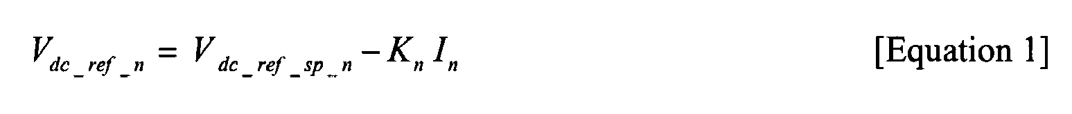
where Vdc_ref_sp_n is the dc link reference voltage set-point value for each power converter n, Kn is the droop rate of each power converter n and In is the output current of each power converter n. - It will be readily appreciated from
Figure 2 that there is a difference ΔI between the output currents I 1 and I 2 of the two parallel-connectedpower converters 1, 2 illustrated inFigure 1 for the same dc link voltage (i.e. output voltage) Vdc and that there is a difference ΔV between the dc link voltages of the twopower converters 1, 2 for the same output current Iave. It will be appreciated fromFigure 2 that the output current Iave is the average of the output currents I 1 and I 2 of the twopower converters 1, 2 for the same dc link voltage Vdc. - Embodiments of the present invention provide a control methodology for modifying the output voltage droop characteristic of each of the
power converters 1, 2 to reduce both the difference ΔI in the output currents I 1 and I 2 of the twopower converters 1, 2 for a given dc link voltage Vdc and the difference ΔV between the dc link voltages of the twopower converters 1, 2 for the same output current Iave. The methodology thus improves both the current sharing performance and the voltage regulation accuracy of the parallel-connectedpower converters 1, 2. - In more detail, the dc link reference voltage Vdc_ref_n of each power converter n is independently variable. A suitable droop controller is provided for this purpose, as will be described later in this specification. Specifically, the dc link reference voltage Vdc_ref_n of each power converter is varied based on the average of the output currents of the plurality of parallel-connected power converters Iave and the output current In of each respective power converter n.
-
Figure 3 illustrates one example of possible modified load regulation characteristics for the two parallel-connectedpower converters 1, 2 illustrated inFigure 1 . Specifically, the output voltage droop characteristic of each of the parallel-connectedpower converters 1, 2 is modified by varying the dc link reference voltage V dc_ref_1 and V dc_ref_2 of eachpower converter 1, 2. In accordance with embodiments of the invention, the dc link reference voltage V dc_ref_1 and V dc_ref_2 of each power converter is varied based on the average of the output currents of the plurality of parallel-connected power converters Iave and the output current I 1 and I 2 of eachrespective power converter 1, 2. In more general terms, the modified dc link reference voltage V'dc_ref_n of each power converter n is determined in accordance with the following equation:
- where (Iave - In ) is the error between the average of the output currents of the plurality of parallel-connected power converters and the output current of the power converter n and k' is an offset adjustment value.
- As a result of the use of the control methodology defined by
equation 2, it will be seen inFigure 3 that the modified dc link reference voltage V' dc_ref_1 of the first power converter 1 is reduced relative to the original dc link reference voltage V dc_ref_1 and that the modified dc link reference voltage V' dc_ref_2 of thesecond power converter 2 is increased relative to the original dc link reference voltage V dc_ref_2 , thereby modifying the output voltage droop characteristics of bothpower converters 1, 2. As a result, there is a decrease in the difference ΔI between the output currents I 1 and I 2 of bothpower converters 1, 2 for the same dc link voltage Vdc and a decrease in the difference ΔV between the dc link voltages of the twopower converters 1, 2 for the same output current Iave. Both the current sharing performance and the voltage regulation performance of thepower converters 1, 2 are thus improved by utilising the control methodology according to embodiments of the present invention. -
Figure 4 is a schematic illustration of one possible embodiment of acontroller 22 for use with at least one, and preferably both, of thepower converters 1, 2 illustrated inFigure 1 which implements the control methodology outlined above. - The
controller 22 is operable to initially measure the instantaneous three-phase currents ia, ib , and ic of eachpower converter 1, 2, for example using suitable current sensors. Thecontroller 22 includes a ForwardPark transformation block 24 which transforms the measured three phase currents ia, ib, and ic from the stationary reference frame into the rotating reference frame to provide amplitude values of the reactive current id and active current iq . The transformation equations implemented by the ForwardPark transformation block 24 are as follows:

where Ia, Ib and Ic are rms values of the measured instantaneous three-phase currents ia, ib and ic of each power converter and ω is the rotation speed (rad/s) of the rotating frame. - The
controller 22 is operable to compare the reactive current id determined by the ForwardPark transformation block 24 with the desired reactive current reference value id_ref by subtracting the reactive current id from the desired reactive current reference value id_ref atcalculation block 26. The output from thecalculation block 26 is fed to acurrent controller 27. In some embodiments, the desired reactive current reference value id_ref may be zero but other values are, of course, possible and entirely within the scope of the claimed invention. - The dc link current idc flowing through the
common dc link 16 is measured and is sent to adroop controller 28 which may form part of thecontroller 22 and which is operable to determine the output voltage droop characteristic of itsrespective power converter 1, 2. The output voltage droop characteristic of eachpower converter 1, 2 is defined by a droop rate and a droop sign, positive or negative, applied to the droop rate. In accordance with embodiments of the invention, thedroop controller 28 is operable (at block 30) to determine whether a positive or negative droop sign should be applied to the droop rate (set by block 32). To do this, thedroop controller 28 determines the direction of flow of the dc link current idc and determines the droop sign based on the direction of current flow through thecommon dc link 16. The direction of current flow is indicative of the direction of power flow through eachpower converter 1, 2. In some embodiments, when eachpower converter 1, 2 operates as a rectifier (when power is supplied to thecommon dc link 16 in power generation applications), the droop sign is positive. In other embodiments, when eachpower converter 1, 2 operates as an inverter (when power is supplied from thecommon dc link 16 in motoring applications), the droop sign is negative. - The product of the active current iq (as determined by the Forward Park transformation block 24) and signed droop rate, performed at
calculation block 33, is sent to alow pass filter 34 which eliminates any high frequency noise. - The
droop controller 28 is operable to modify the output voltage droop characteristic of its respective power converter n, as generally discussed above with respect toFigures 2 and 3 , by varying the dc link reference voltage Vdc_ref_n of the power converter. The average of the output currents of the plurality of parallel-connected power converters Iave is determined by thedroop controller 28 in accordance with the following equation:-
where N is the total number of the parallel-connected power converters and In is the rms value of the output current of each power converter n. In and Iave must comply with the reference frame used by thecontroller 22 and may, therefore, need to be modified accordingly. In this example, thecontroller 22 uses the rotating reference frame and, hence, In and Iave are transformed from the stationary reference frame into the rotating reference frame before In and Iave are inputted into the calculation block 35. In alternative embodiments in which thecontroller 22 uses the three-phase stationary reference frame, In and Iave may be the three-phase currents and their average, respectively. - In accordance with
equation 2, the rms value of the output current In of each power converter 10 is subtracted from the average of the output currents Iave at calculation block 35 and the resultant error is sent to aproportional controller 36 where it is modified in accordance with the offset adjustment value k'. The output of theproportional controller 36, which it will be clearly understood is based on the output current In, and the average of the output currents Iave, is then used to modify the dc link reference voltage Vdc_ref_n at thecalculation block 38. The signed droop rate and the modified dc link reference voltage set-point Vdc_ref_sp are also taken into account by thecalculation block 38 to provide the adaptively controlled dc link reference voltage V'dc_ref, generally in accordance withequation 2. - The error between the modified dc link reference voltage V'dc_ref and the measured dc link voltage Vdc is determined at the
calculation block 40 and any resultant error is used as an input for adc voltage controller 42 which is preferably a proportional-integral (PI) controller. The output of thedc voltage controller 42 is used to determine the active current reference iq_ref. Finally, the active current iq , determined as aforesaid by the ForwardPark transformation block 24, is subtracted, at thecalculation block 44, from the active current reference iq_ref. - The error between the determined active current iq and the active current reference iq_ref is fed to the
current controller 27 along with the error between the determined reactive current id and the reactive current reference id_ref as aforesaid, and thecurrent controller 27 generates suitable PWM command signals to control eachpower converter 1, 2, for example by driving insulated gate bipolar transistors (IGBTs). Eachcontroller 22 operates continuously and in real-time to provide for the active control of its associatedpower converter 1, 2 and, in particular, to provide for the active control of the output voltage droop characteristic of its associatedpower converter 1, 2. Both the current sharing performance and voltage regulation performance are thus improved. - Embodiments of the invention advantageously also provide for synchronisation of any number of parallel-connected power converters 1-N, since even a small phase difference between the power converters can cause an unwanted circulating current, especially under light load. Synchronisation of the power converters is achieved in the following manner.
- The power converters 1-N are connected together to form a cascaded array. More particularly, each power converter includes a controller having an input for receiving a synchronisation signal from the controller of a preceding power converter in the array and an output for transmitting a synchronisation signal to the controller of a succeeding power converter in the array. The controller of the last power converter in the array transmits a synchronisation signal to the controller of the first power converter in the array to complete the connection and form a "closed loop".
- A cascaded array of four
controllers 1a, 2a, 3 a, 4a associated with a cascaded array of four parallel-connected power converters is shown schematically inFigure 5 . The input and output of each controller can be fibre optic channels so that the synchronisation signals are transmitted as optic signals through fibre optic cables, for example. Other means of transmitting the synchronisation signals, such as electrical or radio frequency (RF) signalling, can be used. - Each
controller 1a, 2a, 3a, 4a is arranged to transmit a synchronisation signal consisting of a series of digital time pulses having states 0 and 1. The pulse period (i.e. the time between the falling edges of successive time pulses) can be measured by each controller and the pulse width of the time pulses (i.e. the period of time during which state 1 applies) can be used to provide information about the position the controller that transmits the synchronisation signal has within the array. The way in which eachcontroller 1a, 2a, 3a, 4a, and hence its associated power converter, is allocated a role as a "master" or "slave" is described in more detail below with continued reference toFigure 5 . - In a situation where all four of the power converters in the array are connected in sequence and operating normally, the controller 1 a of the first power converter may be the "master" controller and the
controllers 2a, 3a, 4a of the second, third and fourth power converters may be the "slave" controllers. In this example, the controller 1a of the first power converter outputs to the controller 2a of the second power converter a first synchronisation signal S1 having a pulse width t. The controller 2a of the second power converter receives the first synchronisation signal S1 having a pulse width t and identifies its position as the second power converter in the array based on the pulse width t of the first synchronisation signal S1. - The controller 2a of the second power converter outputs a second synchronisation signal S2 having a
pulse width 2t. The controller 3a of the third power converter receives the second synchronisation signal S2 having apulse width 2t and identifies its position as the third power converter in the array based on thepulse width 2t of the second synchronisation signal S2. - The controller 3a of the third power converter outputs a third synchronisation signal S3 having a
pulse width 3t. Thecontroller 4a of the fourth power converter receives the third synchronisation signal S3 having apulse width 3t and identifies its position as the fourth power converter in the array based on thepulse width 3t of the third synchronisation signal S3. - The
controller 4a of the fourth power converter outputs a fourth synchronisation signal S4 having apulse width 4t. The controller 1a of the first power converter receives the fourth synchronisation signal S4 ofpulse width 4t which confirms its role as a "master" controller and its operation thus remains unchanged. - The
controllers 1a, 2a, 3a, 4a of the parallel-connected power converters, and hence the power converters themselves, are determined to be a "master" or a "slave" depending on when they come on-line. The controller of the power converter in the array that is the first to come on-line preferably assumes a role as a "master" controller and takes a position as the first controller in the array. Any controller that receives a synchronisation signal when its power converter comes on-line will preferably assume a role as a "slave" controller. Any "slave" controller that fails to receive a synchronisation signal for any reason (i.e. the immediately preceding controller in the array goes off-line or the synchronisation signal is disrupted) may assume a role as a "master" controller. - The cascaded array of power converters functions normally until one of the power converters goes off-line or one of the synchronisation signals is otherwise disrupted. For example, if the first power converter goes off-line or the first synchronisation signal S1 is disrupted, the controller 2a of the second power converter no longer receives a synchronisation signal. The controller 2a of the second power converter thus assumes the role of the "master" controller and takes the first position in the array. The controller 2a now outputs a first synchronisation signal S1 having a pulse width t. The controller 3a of the third power converter receives the first synchronisation signal S1 of pulse width t and takes a role as a "slave" controller because it is receiving a synchronisation signal, but now takes the second position in the array.
- The controller 3a of the third power converter now outputs a second synchronisation signal S2 having a
pulse width 2t. Thecontroller 4a of the fourth power converter receives the second synchronisation signal S2 ofpulse width 2t and takes a role as a "slave" controller because it is receiving a synchronisation signal, but now takes the third position in the array. - The
controller 4a of the fourth power converter now outputs a third synchronisation signal S3 having apulse width 3t. When the first power converter comes back on-line, the controller 1a of the first power converter receives the third synchronisation signal S3 and assumes a role as a "slave" power converter because it is receiving a synchronisation signal. The controller 1a, and hence the first power converter, thus takes the fourth position in the array. - The controller 1 a of the first power converter outputs a fourth synchronisation signal S4 having a
pulse width 4t. The controller 2a of the second power converter receives the fourth synchronisation signal S4 which confirms its role as a "master" power converter and its operation remains unchanged. - It will be appreciated from the foregoing that synchronisation of the parallel-connected power converters can be maintained, and that the power converters can continue to operate effectively, in the event of a fault occurring in any one or more of the power converters. Reliability is thus significantly improved when the parallel-connected power converters operate as a cascaded array.
- Although embodiments of the invention have been described in the preceding paragraphs with reference to various examples, it should be understood that various modifications may be made to those examples without departing from the scope of the present invention, as claimed.
- For example, the output voltage droop characteristic of only one of the
power converters 1, 2 could be modified by varying the dc link reference voltage Vdc_ref of therespective power converter 1, 2 based on the average of the output currents of the plurality of parallel-connected power converters Iave and the output current In of the respective one of thepower converters 1, 2. The methodology may be employed with any number of power converters connected in parallel, whether they operate as active rectifiers and/or active inverters. - Although the droop rates of the
power converters 1, 2 are shown to be the same as each other inFigures 2 and 3 , it should be understood that the methodology described above is equally applicable when the droop rates of parallel-connected power converters are different.
Claims (15)
- A method for controlling a plurality of power converters connected in parallel between an ac arrangement and a common dc link, each of the power converters operating in accordance with a pulse width modulation (PWM) strategy and having an independently variable dc link reference voltage, the method comprising modifying an output voltage droop characteristic of at least one of the plurality of parallel-connected power converters by varying the dc link reference voltage of the at least one power converter based on the output current of the at least one power converter and the average of the output currents of the plurality of power converters.
- A method according to claim 1, wherein the method comprises modifying the output voltage droop characteristic of each of the plurality of parallel-connected power converters by varying the dc link reference voltage of each power converter based on the output current of each respective power converter and the average of the output currents of the plurality of power converters.
- A method according to claim 1 or claim 2, wherein the method comprises continuously measuring the output current of the or each power converter and continuously determining the average of the output currents of the plurality of power converters to thereby actively modify the output voltage droop characteristic of the or each power converter by varying the dc link reference voltage of the or each power converter.
- A method according to any preceding claim, wherein the method comprises modifying the output voltage droop characteristic of a first power converter by decreasing the dc link reference voltage of the first power converter and modifying the output voltage droop characteristic of a second power converter by increasing the dc link reference voltage of the second power converter.
- A method according to any preceding claim, wherein the method comprises varying the dc link reference voltage of the or each power converter based on the error between the average of the output currents of the plurality of power converters and the rms output current of the or each respective power converter.
- A method according to any preceding claim, wherein the output voltage droop characteristic of the or each power converter is defined by a droop rate and a droop sign applied to the droop rate, the step of controlling the output voltage droop characteristic of at least one of the plurality of power converters further comprising determining the droop sign.
- A method according to claim 6, wherein the step of determining the droop sign comprises determining the direction of current flow through the common dc link.
- A method according to any preceding claim, wherein the method comprises synchronising the parallel-connected power converters by providing each of the power converters with a synchronisation signal.
- A method according to any preceding claim, in which the PWM strategy of each power converter is defined by an independent voltage carrier signal and an independently controllable modulating sinusoidal voltage signal which are used to generate a PWM command signal for each PWM strategy, wherein the voltage carrier signals of the PWM strategies have the same switching period and wherein any desynchronisation of the PWM command signals causes an unwanted circulating current to flow between the power converters, the method comprising providing the independently controllable modulating sinusoidal voltage signal of the PWM strategy of at least one of the power converters with a dc voltage offset to modify the PWM command signal of the at least one power converter and thereby increase the synchronisation of the PWM command signals so that the magnitude of any unwanted circulating current is reduced.
- A plurality of power converters connected in parallel between an ac arrangement and a common dc link, each of the power converters operating in accordance with a pulse width modulation (PWM) strategy and having an individually variable dc link reference voltage, at least one of the power converters including a droop controller for controlling the output voltage droop characteristic of the power converter, wherein the droop controller is operable to modify the output voltage droop characteristic by varying the dc link reference voltage of the at least one power converter based on the output current of the at least one power converter and the average of the output currents of the plurality of power converters.
- A plurality of parallel-connected power converters according to claim 10, wherein each of the power converters includes a droop controller and each droop controller is operable to modify the output voltage droop characteristic of its respective power converter by varying the dc link reference voltage of the power converter based on the output current of the power converter and the average of the output currents of the plurality of power converters.
- A plurality of parallel-connected power converters according to claim 10 or claim 11, wherein the or each droop controller is operable to actively vary the dc link reference voltage of its respective power converter based on continuous determinations of the output current of its respective power converter and the average of the output currents of the plurality of power converters.
- A plurality of parallel-connected power converters according to any of claims 10 to 12, wherein the output voltage droop characteristic of the or each power converter is defined by a droop rate and a droop sign applied to the droop rate, the or each droop controller being operable to control the output voltage droop characteristic of its respective power converter by determining the droop sign.
- A plurality of parallel-connected power converters according to claim 13, wherein the or each droop controller is operable to determine the droop sign by determining the direction of current flow through the common dc link.
- A plurality of parallel-connected power converters according to any of claims 10 to 14, wherein some or all of the parallel-connected power converters are operable as active rectifiers or active inverters.
Priority Applications (4)
| Application Number | Priority Date | Filing Date | Title |
|---|---|---|---|
| EP09251710A EP2270969B8 (en) | 2009-07-02 | 2009-07-02 | Control methods for parallel-connected power converters |
| AT09251710T ATE545193T1 (en) | 2009-07-02 | 2009-07-02 | CONTROL METHOD FOR PARALLEL-CONNECTED CURRENT TRANSFORMERS |
| PCT/EP2010/003846 WO2011000511A2 (en) | 2009-07-02 | 2010-06-29 | Control methods for parallel-connected power converters |
| US13/380,082 US20120243274A1 (en) | 2009-07-02 | 2010-06-29 | Control Methods for Parallel-Connected Power Converters |
Applications Claiming Priority (1)
| Application Number | Priority Date | Filing Date | Title |
|---|---|---|---|
| EP09251710A EP2270969B8 (en) | 2009-07-02 | 2009-07-02 | Control methods for parallel-connected power converters |
Publications (3)
| Publication Number | Publication Date |
|---|---|
| EP2270969A1 true EP2270969A1 (en) | 2011-01-05 |
| EP2270969B1 EP2270969B1 (en) | 2012-02-08 |
| EP2270969B8 EP2270969B8 (en) | 2012-04-11 |
Family
ID=41402573
Family Applications (1)
| Application Number | Title | Priority Date | Filing Date |
|---|---|---|---|
| EP09251710A Not-in-force EP2270969B8 (en) | 2009-07-02 | 2009-07-02 | Control methods for parallel-connected power converters |
Country Status (4)
| Country | Link |
|---|---|
| US (1) | US20120243274A1 (en) |
| EP (1) | EP2270969B8 (en) |
| AT (1) | ATE545193T1 (en) |
| WO (1) | WO2011000511A2 (en) |
Cited By (7)
| Publication number | Priority date | Publication date | Assignee | Title |
|---|---|---|---|---|
| US20120217802A1 (en) * | 2011-02-26 | 2012-08-30 | General Electric Company | System and method for power sharing of front-end converters without communication link in a modular-stacked dc transmission system |
| CN103227581A (en) * | 2013-05-10 | 2013-07-31 | 湖南大学 | Inverter parallel harmonic wave ring current restraining method for controlling harmonic wave droop |
| CN104659813A (en) * | 2015-02-04 | 2015-05-27 | 湖南大学 | Multiple-inverter parallel control method for quickly restraining harmonic circulating current |
| EP2804309A4 (en) * | 2012-01-11 | 2016-05-04 | Toshiba Mitsubishi Elec Inc | ELECTRONIC POWER CONVERSION DEVICE AT THREE LEVELS |
| EP2492504B1 (en) | 2011-02-25 | 2018-01-31 | Siemens Aktiengesellschaft | Wind turbine |
| WO2018206085A1 (en) * | 2017-05-09 | 2018-11-15 | Ge Energy Power Conversion Technology Ltd | Methods and apparatus of controllers for power converter with parallel power channels having independent dc buses |
| CN111316522B (en) * | 2017-11-14 | 2021-08-31 | Abb电网瑞士股份公司 | Voltage droop-based approach in power transmission systems |
Families Citing this family (24)
| Publication number | Priority date | Publication date | Assignee | Title |
|---|---|---|---|---|
| EP2382701B1 (en) | 2009-01-16 | 2016-11-30 | Boulder Wind Power, Inc. | Segmented stator for an axial field device |
| WO2010119256A1 (en) | 2009-04-17 | 2010-10-21 | Isis Innovation Limited | Composition for delivery of genetic material |
| US9154024B2 (en) | 2010-06-02 | 2015-10-06 | Boulder Wind Power, Inc. | Systems and methods for improved direct drive generators |
| GB201121070D0 (en) | 2011-12-07 | 2012-01-18 | Isis Innovation | composition for delivery of biotherapeutics |
| CN103378742B (en) * | 2012-04-18 | 2016-02-03 | 台达电子企业管理(上海)有限公司 | Converter system and control method thereof |
| US8736133B1 (en) | 2013-03-14 | 2014-05-27 | Boulder Wind Power, Inc. | Methods and apparatus for overlapping windings |
| CN103219906B (en) * | 2013-04-10 | 2015-07-22 | 哈尔滨工程大学 | Method for suppressing active circulation with parallel three-phase inverters |
| US20150145462A1 (en) * | 2013-11-25 | 2015-05-28 | Rockwell Automation Technologies, Inc. | Method and apparatus for current auto balancing for parallel converter systems |
| US10177620B2 (en) | 2014-05-05 | 2019-01-08 | Boulder Wind Power, Inc. | Methods and apparatus for segmenting a machine |
| US9698589B1 (en) | 2014-06-09 | 2017-07-04 | Google Inc. | DC power distribution architectures |
| US10008854B2 (en) | 2015-02-19 | 2018-06-26 | Enphase Energy, Inc. | Method and apparatus for time-domain droop control with integrated phasor current control |
| US10996704B2 (en) * | 2015-06-12 | 2021-05-04 | Enphase Energy, Inc. | Method and apparatus for control of intelligent loads in microgrids |
| US10050551B1 (en) * | 2015-07-28 | 2018-08-14 | Abb Schweiz Ag | Arrangement, method and computer program product for limiting circulating currents |
| US10097095B2 (en) | 2016-09-21 | 2018-10-09 | General Electric Company | DC converters with modified droop control and method of use |
| US10348184B2 (en) | 2017-08-14 | 2019-07-09 | Ge Global Sourcing Llc | Power system and an associated method thereof |
| US10840706B2 (en) * | 2018-02-28 | 2020-11-17 | Inventus Holdings, Llc | Voltage droop compensation for a utility power system |
| DE102018115490A1 (en) | 2018-06-27 | 2020-01-02 | Vacon Oy | Method of reducing common mode current in power electronics equipment |
| CN109066820B (en) * | 2018-10-23 | 2024-06-11 | 四川大学 | Power sharing device and control method of parallel inverters based on current droop characteristics |
| EP4175142A1 (en) | 2021-10-27 | 2023-05-03 | Siemens Gamesa Renewable Energy Innovation & Technology S.L. | Power conversion system and operating method |
| EP4254711A1 (en) * | 2022-03-30 | 2023-10-04 | Danfoss Editron Oy | A method and a control system for controlling parallel connected power converters |
| EP4555616A1 (en) * | 2022-07-11 | 2025-05-21 | Nextracker LLC | Parallel inverter systems and methods |
| TWI870844B (en) * | 2023-05-03 | 2025-01-21 | 幸康電子股份有限公司 | Parallel power conversion system and parallel controller thereof |
| DE102023210240A1 (en) | 2023-10-18 | 2025-04-24 | Robert Bosch Gesellschaft mit beschränkter Haftung | Method for operating several parallel-connected active rectifiers |
| DE102024113783A1 (en) * | 2024-05-16 | 2025-11-20 | Schaeffler Technologies AG & Co. KG | Electrical circuit arrangement for controlling and/or driving electrical machines |
Citations (3)
| Publication number | Priority date | Publication date | Assignee | Title |
|---|---|---|---|---|
| JPH05308777A (en) * | 1992-04-30 | 1993-11-19 | Hitachi Ltd | Uninterruptible power unit |
| US20040032755A1 (en) * | 2002-06-13 | 2004-02-19 | Riku Pollanen | Method in connection with converter bridges |
| EP2020740A1 (en) * | 2006-05-23 | 2009-02-04 | Mitsubishi Denki Kabushiki Kaisha | Power converter |
Family Cites Families (4)
| Publication number | Priority date | Publication date | Assignee | Title |
|---|---|---|---|---|
| JP3251628B2 (en) * | 1992-03-06 | 2002-01-28 | 三菱電機株式会社 | Elevator speed control device |
| US6801026B2 (en) * | 2002-12-20 | 2004-10-05 | Intel Corporation | Hysteretic DC-DC converters |
| JP2006149153A (en) * | 2004-11-24 | 2006-06-08 | Mitsubishi Electric Corp | Motor control device |
| TW200939632A (en) * | 2008-03-11 | 2009-09-16 | Richtek Technology Corp | Rapid response generating circuit and the method thereof, multi-phase voltage regulator and the rapid response method |
-
2009
- 2009-07-02 AT AT09251710T patent/ATE545193T1/en active
- 2009-07-02 EP EP09251710A patent/EP2270969B8/en not_active Not-in-force
-
2010
- 2010-06-29 US US13/380,082 patent/US20120243274A1/en not_active Abandoned
- 2010-06-29 WO PCT/EP2010/003846 patent/WO2011000511A2/en not_active Ceased
Patent Citations (3)
| Publication number | Priority date | Publication date | Assignee | Title |
|---|---|---|---|---|
| JPH05308777A (en) * | 1992-04-30 | 1993-11-19 | Hitachi Ltd | Uninterruptible power unit |
| US20040032755A1 (en) * | 2002-06-13 | 2004-02-19 | Riku Pollanen | Method in connection with converter bridges |
| EP2020740A1 (en) * | 2006-05-23 | 2009-02-04 | Mitsubishi Denki Kabushiki Kaisha | Power converter |
Non-Patent Citations (1)
| Title |
|---|
| ZHIHONG YE ET AL: "Control of circulating current in parallel three-phase boost rectifiers", APEC 2000. FIFTEENTH ANNUAL IEEE APPLIED POWER ELECTRONICS CONFERENCE AND EXPOSITION, vol. 1, 2000, IEEE PISCATAWAY, NJ, USA, pages 506 - 512, XP002561009, ISBN: 0-7803-5864-3 * |
Cited By (15)
| Publication number | Priority date | Publication date | Assignee | Title |
|---|---|---|---|---|
| EP2492504B1 (en) | 2011-02-25 | 2018-01-31 | Siemens Aktiengesellschaft | Wind turbine |
| US20120217802A1 (en) * | 2011-02-26 | 2012-08-30 | General Electric Company | System and method for power sharing of front-end converters without communication link in a modular-stacked dc transmission system |
| US8624431B2 (en) * | 2011-02-26 | 2014-01-07 | General Electric Company | System and method for power sharing of front-end converters without communication link in a modular-stacked DC transmission system |
| CN103650280B (en) * | 2011-02-26 | 2016-09-21 | 通用电气公司 | The system and method shared without the power of front end converter during communication link in modular stacked DC transmission system |
| CN103650280A (en) * | 2011-02-26 | 2014-03-19 | 通用电气公司 | System and method for power sharing front-end converters without communication link in a modular-stacked dc transmission system |
| AU2012225872B2 (en) * | 2011-02-26 | 2016-06-02 | General Electric Company | System and method for power sharing front-end converters without communication link in a modular-stacked DC transmission system |
| EP2804309A4 (en) * | 2012-01-11 | 2016-05-04 | Toshiba Mitsubishi Elec Inc | ELECTRONIC POWER CONVERSION DEVICE AT THREE LEVELS |
| US9374033B2 (en) | 2012-01-11 | 2016-06-21 | Toshiba Mitsubishi-Electric Industrial Systems Corporation | Three-level power conversion apparatus |
| CN103227581B (en) * | 2013-05-10 | 2014-01-22 | 湖南大学 | Inverter parallel harmonic wave ring current restraining method for controlling harmonic wave droop |
| CN103227581A (en) * | 2013-05-10 | 2013-07-31 | 湖南大学 | Inverter parallel harmonic wave ring current restraining method for controlling harmonic wave droop |
| CN104659813A (en) * | 2015-02-04 | 2015-05-27 | 湖南大学 | Multiple-inverter parallel control method for quickly restraining harmonic circulating current |
| WO2018206085A1 (en) * | 2017-05-09 | 2018-11-15 | Ge Energy Power Conversion Technology Ltd | Methods and apparatus of controllers for power converter with parallel power channels having independent dc buses |
| EP3646455A1 (en) * | 2017-05-09 | 2020-05-06 | GE Energy Power Conversion Technology Ltd. | Methods and apparatus of controllers for power converter with parallel power channels having independent dc buses |
| CN111316522B (en) * | 2017-11-14 | 2021-08-31 | Abb电网瑞士股份公司 | Voltage droop-based approach in power transmission systems |
| EP3711134B1 (en) | 2017-11-14 | 2022-01-05 | Hitachi Energy Switzerland AG | Voltage droop-based method in a power transmission system |
Also Published As
| Publication number | Publication date |
|---|---|
| WO2011000511A2 (en) | 2011-01-06 |
| EP2270969B1 (en) | 2012-02-08 |
| US20120243274A1 (en) | 2012-09-27 |
| EP2270969B8 (en) | 2012-04-11 |
| ATE545193T1 (en) | 2012-02-15 |
| WO2011000511A3 (en) | 2011-04-21 |
Similar Documents
| Publication | Publication Date | Title |
|---|---|---|
| EP2270969B1 (en) | Control methods for parallel-connected power converters | |
| EP2270970B1 (en) | Control methods for the synchronisation of parallel-connected power converters operating in accordance with a pulse width modulation (PWM) strategy | |
| EP2793392B1 (en) | Controller for controlling a power converter | |
| EP2485358B1 (en) | System and method for mitigating an electric unbalance of a three-phase current at a Point of Common Coupling between a wind farm and a power grid | |
| US9973125B2 (en) | Operating a wind turbine being connected to a utility grid solely via an umbilical AC cable with a network bridge controller performing a power and a voltage control | |
| KR101474564B1 (en) | Of Phase Shift and Synchronization Control in Pulse Width Modulation of Power Converter | |
| EP3116086B1 (en) | Operating a wind turbine being connected to a utility grid both via a hvdc power connection and via an umbilical ac cable with a network bridge controller performing a power and a voltage control | |
| EP3116087A1 (en) | Wind turbine connected to a utility grid via a hvdc power connection through a network bridge controller with power and voltage control | |
| GB2449119A (en) | AC-AC converter | |
| EP2750270A1 (en) | Harmonic current controller | |
| EP3806318B1 (en) | Variable-speed power generation electric device | |
| EP2725701B1 (en) | Current balance control in converter for doubly fed induction generator wind turbine system | |
| JP3838093B2 (en) | Grid interconnection power converter | |
| EP3736940A1 (en) | System and method for coordinated control of reactive power from a generator and a reactive power compensation device in a wind turbine system | |
| EP3982531B1 (en) | Power converters | |
| JP4838031B2 (en) | Multiple inverter control system | |
| Sepahvand et al. | Fault recovery strategy for hybrid cascaded H-bridge multi-level inverters | |
| US20230093800A1 (en) | Control unit and method for a converter | |
| CA2835303C (en) | System and method for optimization of dual bridge doubly fed induction generator (dfig) | |
| EP4436027A1 (en) | Dc link voltage control for electrical converters with multiple branches | |
| EP4207579A1 (en) | Double winding electric machine assembly | |
| EP3975418A1 (en) | Systems and methods of multi-motor regenerative drive |
Legal Events
| Date | Code | Title | Description |
|---|---|---|---|
| PUAI | Public reference made under article 153(3) epc to a published international application that has entered the european phase |
Free format text: ORIGINAL CODE: 0009012 |
|
| AK | Designated contracting states |
Kind code of ref document: A1 Designated state(s): AT BE BG CH CY CZ DE DK EE ES FI FR GB GR HR HU IE IS IT LI LT LU LV MC MK MT NL NO PL PT RO SE SI SK SM TR |
|
| AX | Request for extension of the european patent |
Extension state: AL BA RS |
|
| 17P | Request for examination filed |
Effective date: 20110624 |
|
| GRAP | Despatch of communication of intention to grant a patent |
Free format text: ORIGINAL CODE: EPIDOSNIGR1 |
|
| RIC1 | Information provided on ipc code assigned before grant |
Ipc: H02M 7/23 20060101AFI20110802BHEP |
|
| RIN1 | Information on inventor provided before grant (corrected) |
Inventor name: WEBB, RICHARD STUART Inventor name: MORENO CASTENEDA, VEIMAR YOBANY Inventor name: KNIGHT, JEREMY STEPHEN PREVOST Inventor name: FENG, CHUNMEI |
|
| GRAS | Grant fee paid |
Free format text: ORIGINAL CODE: EPIDOSNIGR3 |
|
| GRAA | (expected) grant |
Free format text: ORIGINAL CODE: 0009210 |
|
| AK | Designated contracting states |
Kind code of ref document: B1 Designated state(s): AT BE BG CH CY CZ DE DK EE ES FI FR GB GR HR HU IE IS IT LI LT LU LV MC MK MT NL NO PL PT RO SE SI SK SM TR |
|
| REG | Reference to a national code |
Ref country code: GB Ref legal event code: FG4D |
|
| REG | Reference to a national code |
Ref country code: AT Ref legal event code: REF Ref document number: 545193 Country of ref document: AT Kind code of ref document: T Effective date: 20120215 Ref country code: CH Ref legal event code: EP |
|
| RIN2 | Information on inventor provided after grant (corrected) |
Inventor name: KNIGHT, JEREMY STEPHEN PREVOST Inventor name: MORENO CASTANEDA, VEIMAR YOBANY Inventor name: WEBB, RICHARD STUART Inventor name: FENG, CHUNMEI |
|
| RIN2 | Information on inventor provided after grant (corrected) |
Inventor name: FENG, CHUNMEI Inventor name: WEBB, RICHARD STUART Inventor name: KNIGHT, JEREMY STEPHEN PREVOST Inventor name: MORENO-CASTANEDA, VEIMAR YOBANY |
|
| REG | Reference to a national code |
Ref country code: DE Ref legal event code: R096 Ref document number: 602009005212 Country of ref document: DE Effective date: 20120405 |
|
| REG | Reference to a national code |
Ref country code: SE Ref legal event code: TRGR |
|
| REG | Reference to a national code |
Ref country code: NL Ref legal event code: VDEP Effective date: 20120208 |
|
| REG | Reference to a national code |
Ref country code: CH Ref legal event code: NV Representative=s name: CRONIN INTELLECTUAL PROPERTY |
|
| REG | Reference to a national code |
Ref country code: NO Ref legal event code: T2 Effective date: 20120208 |
|
| LTIE | Lt: invalidation of european patent or patent extension |
Effective date: 20120208 |
|
| PG25 | Lapsed in a contracting state [announced via postgrant information from national office to epo] |
Ref country code: HR Free format text: LAPSE BECAUSE OF FAILURE TO SUBMIT A TRANSLATION OF THE DESCRIPTION OR TO PAY THE FEE WITHIN THE PRESCRIBED TIME-LIMIT Effective date: 20120208 Ref country code: LT Free format text: LAPSE BECAUSE OF FAILURE TO SUBMIT A TRANSLATION OF THE DESCRIPTION OR TO PAY THE FEE WITHIN THE PRESCRIBED TIME-LIMIT Effective date: 20120208 Ref country code: IS Free format text: LAPSE BECAUSE OF FAILURE TO SUBMIT A TRANSLATION OF THE DESCRIPTION OR TO PAY THE FEE WITHIN THE PRESCRIBED TIME-LIMIT Effective date: 20120608 Ref country code: NL Free format text: LAPSE BECAUSE OF FAILURE TO SUBMIT A TRANSLATION OF THE DESCRIPTION OR TO PAY THE FEE WITHIN THE PRESCRIBED TIME-LIMIT Effective date: 20120208 |
|
| PG25 | Lapsed in a contracting state [announced via postgrant information from national office to epo] |
Ref country code: BE Free format text: LAPSE BECAUSE OF FAILURE TO SUBMIT A TRANSLATION OF THE DESCRIPTION OR TO PAY THE FEE WITHIN THE PRESCRIBED TIME-LIMIT Effective date: 20120208 Ref country code: PL Free format text: LAPSE BECAUSE OF FAILURE TO SUBMIT A TRANSLATION OF THE DESCRIPTION OR TO PAY THE FEE WITHIN THE PRESCRIBED TIME-LIMIT Effective date: 20120208 Ref country code: PT Free format text: LAPSE BECAUSE OF FAILURE TO SUBMIT A TRANSLATION OF THE DESCRIPTION OR TO PAY THE FEE WITHIN THE PRESCRIBED TIME-LIMIT Effective date: 20120608 Ref country code: LV Free format text: LAPSE BECAUSE OF FAILURE TO SUBMIT A TRANSLATION OF THE DESCRIPTION OR TO PAY THE FEE WITHIN THE PRESCRIBED TIME-LIMIT Effective date: 20120208 Ref country code: GR Free format text: LAPSE BECAUSE OF FAILURE TO SUBMIT A TRANSLATION OF THE DESCRIPTION OR TO PAY THE FEE WITHIN THE PRESCRIBED TIME-LIMIT Effective date: 20120509 |
|
| PG25 | Lapsed in a contracting state [announced via postgrant information from national office to epo] |
Ref country code: CY Free format text: LAPSE BECAUSE OF FAILURE TO SUBMIT A TRANSLATION OF THE DESCRIPTION OR TO PAY THE FEE WITHIN THE PRESCRIBED TIME-LIMIT Effective date: 20120208 |
|
| PG25 | Lapsed in a contracting state [announced via postgrant information from national office to epo] |
Ref country code: CZ Free format text: LAPSE BECAUSE OF FAILURE TO SUBMIT A TRANSLATION OF THE DESCRIPTION OR TO PAY THE FEE WITHIN THE PRESCRIBED TIME-LIMIT Effective date: 20120208 Ref country code: DK Free format text: LAPSE BECAUSE OF FAILURE TO SUBMIT A TRANSLATION OF THE DESCRIPTION OR TO PAY THE FEE WITHIN THE PRESCRIBED TIME-LIMIT Effective date: 20120208 Ref country code: RO Free format text: LAPSE BECAUSE OF FAILURE TO SUBMIT A TRANSLATION OF THE DESCRIPTION OR TO PAY THE FEE WITHIN THE PRESCRIBED TIME-LIMIT Effective date: 20120208 Ref country code: EE Free format text: LAPSE BECAUSE OF FAILURE TO SUBMIT A TRANSLATION OF THE DESCRIPTION OR TO PAY THE FEE WITHIN THE PRESCRIBED TIME-LIMIT Effective date: 20120208 Ref country code: SI Free format text: LAPSE BECAUSE OF FAILURE TO SUBMIT A TRANSLATION OF THE DESCRIPTION OR TO PAY THE FEE WITHIN THE PRESCRIBED TIME-LIMIT Effective date: 20120208 |
|
| REG | Reference to a national code |
Ref country code: AT Ref legal event code: MK05 Ref document number: 545193 Country of ref document: AT Kind code of ref document: T Effective date: 20120208 |
|
| PG25 | Lapsed in a contracting state [announced via postgrant information from national office to epo] |
Ref country code: SK Free format text: LAPSE BECAUSE OF FAILURE TO SUBMIT A TRANSLATION OF THE DESCRIPTION OR TO PAY THE FEE WITHIN THE PRESCRIBED TIME-LIMIT Effective date: 20120208 |
|
| PLBE | No opposition filed within time limit |
Free format text: ORIGINAL CODE: 0009261 |
|
| STAA | Information on the status of an ep patent application or granted ep patent |
Free format text: STATUS: NO OPPOSITION FILED WITHIN TIME LIMIT |
|
| 26N | No opposition filed |
Effective date: 20121109 |
|
| PG25 | Lapsed in a contracting state [announced via postgrant information from national office to epo] |
Ref country code: AT Free format text: LAPSE BECAUSE OF FAILURE TO SUBMIT A TRANSLATION OF THE DESCRIPTION OR TO PAY THE FEE WITHIN THE PRESCRIBED TIME-LIMIT Effective date: 20120208 |
|
| PG25 | Lapsed in a contracting state [announced via postgrant information from national office to epo] |
Ref country code: MC Free format text: LAPSE BECAUSE OF NON-PAYMENT OF DUE FEES Effective date: 20120731 Ref country code: MK Free format text: LAPSE BECAUSE OF FAILURE TO SUBMIT A TRANSLATION OF THE DESCRIPTION OR TO PAY THE FEE WITHIN THE PRESCRIBED TIME-LIMIT Effective date: 20120208 |
|
| REG | Reference to a national code |
Ref country code: DE Ref legal event code: R097 Ref document number: 602009005212 Country of ref document: DE Effective date: 20121109 |
|
| PG25 | Lapsed in a contracting state [announced via postgrant information from national office to epo] |
Ref country code: ES Free format text: LAPSE BECAUSE OF FAILURE TO SUBMIT A TRANSLATION OF THE DESCRIPTION OR TO PAY THE FEE WITHIN THE PRESCRIBED TIME-LIMIT Effective date: 20120519 |
|
| REG | Reference to a national code |
Ref country code: IE Ref legal event code: MM4A |
|
| PG25 | Lapsed in a contracting state [announced via postgrant information from national office to epo] |
Ref country code: BG Free format text: LAPSE BECAUSE OF FAILURE TO SUBMIT A TRANSLATION OF THE DESCRIPTION OR TO PAY THE FEE WITHIN THE PRESCRIBED TIME-LIMIT Effective date: 20120508 Ref country code: IE Free format text: LAPSE BECAUSE OF NON-PAYMENT OF DUE FEES Effective date: 20120702 Ref country code: MT Free format text: LAPSE BECAUSE OF FAILURE TO SUBMIT A TRANSLATION OF THE DESCRIPTION OR TO PAY THE FEE WITHIN THE PRESCRIBED TIME-LIMIT Effective date: 20120208 |
|
| REG | Reference to a national code |
Ref country code: DE Ref legal event code: R082 Ref document number: 602009005212 Country of ref document: DE Representative=s name: RUEGER | ABEL PATENT- UND RECHTSANWAELTE, DE Country of ref document: DE Representative=s name: RUEGER, BARTHELT & ABEL PATENTANWAELTE, DE Ref country code: DE Ref legal event code: R082 Ref document number: 602009005212 Ref country code: DE Ref legal event code: R082 Ref document number: 602009005212 Country of ref document: DE Representative=s name: RUEGER ABEL PATENT- UND RECHTSANWAELTE, DE |
|
| PG25 | Lapsed in a contracting state [announced via postgrant information from national office to epo] |
Ref country code: TR Free format text: LAPSE BECAUSE OF FAILURE TO SUBMIT A TRANSLATION OF THE DESCRIPTION OR TO PAY THE FEE WITHIN THE PRESCRIBED TIME-LIMIT Effective date: 20120208 |
|
| PG25 | Lapsed in a contracting state [announced via postgrant information from national office to epo] |
Ref country code: LU Free format text: LAPSE BECAUSE OF NON-PAYMENT OF DUE FEES Effective date: 20120702 Ref country code: SM Free format text: LAPSE BECAUSE OF FAILURE TO SUBMIT A TRANSLATION OF THE DESCRIPTION OR TO PAY THE FEE WITHIN THE PRESCRIBED TIME-LIMIT Effective date: 20120208 |
|
| PG25 | Lapsed in a contracting state [announced via postgrant information from national office to epo] |
Ref country code: HU Free format text: LAPSE BECAUSE OF FAILURE TO SUBMIT A TRANSLATION OF THE DESCRIPTION OR TO PAY THE FEE WITHIN THE PRESCRIBED TIME-LIMIT Effective date: 20090702 |
|
| PGFP | Annual fee paid to national office [announced via postgrant information from national office to epo] |
Ref country code: FI Payment date: 20140729 Year of fee payment: 6 Ref country code: DE Payment date: 20140729 Year of fee payment: 6 Ref country code: NO Payment date: 20140729 Year of fee payment: 6 Ref country code: CH Payment date: 20140728 Year of fee payment: 6 |
|
| PGFP | Annual fee paid to national office [announced via postgrant information from national office to epo] |
Ref country code: FR Payment date: 20140717 Year of fee payment: 6 Ref country code: SE Payment date: 20140729 Year of fee payment: 6 Ref country code: GB Payment date: 20140729 Year of fee payment: 6 |
|
| PGFP | Annual fee paid to national office [announced via postgrant information from national office to epo] |
Ref country code: IT Payment date: 20140721 Year of fee payment: 6 |
|
| REG | Reference to a national code |
Ref country code: DE Ref legal event code: R119 Ref document number: 602009005212 Country of ref document: DE |
|
| REG | Reference to a national code |
Ref country code: NO Ref legal event code: MMEP Ref country code: CH Ref legal event code: PL |
|
| REG | Reference to a national code |
Ref country code: SE Ref legal event code: EUG |
|
| GBPC | Gb: european patent ceased through non-payment of renewal fee |
Effective date: 20150702 |
|
| PG25 | Lapsed in a contracting state [announced via postgrant information from national office to epo] |
Ref country code: GB Free format text: LAPSE BECAUSE OF NON-PAYMENT OF DUE FEES Effective date: 20150702 Ref country code: NO Free format text: LAPSE BECAUSE OF NON-PAYMENT OF DUE FEES Effective date: 20150731 Ref country code: LI Free format text: LAPSE BECAUSE OF NON-PAYMENT OF DUE FEES Effective date: 20150731 Ref country code: DE Free format text: LAPSE BECAUSE OF NON-PAYMENT OF DUE FEES Effective date: 20160202 Ref country code: CH Free format text: LAPSE BECAUSE OF NON-PAYMENT OF DUE FEES Effective date: 20150731 Ref country code: IT Free format text: LAPSE BECAUSE OF NON-PAYMENT OF DUE FEES Effective date: 20150702 |
|
| REG | Reference to a national code |
Ref country code: FR Ref legal event code: ST Effective date: 20160331 |
|
| PG25 | Lapsed in a contracting state [announced via postgrant information from national office to epo] |
Ref country code: FI Free format text: LAPSE BECAUSE OF NON-PAYMENT OF DUE FEES Effective date: 20150702 Ref country code: SE Free format text: LAPSE BECAUSE OF NON-PAYMENT OF DUE FEES Effective date: 20150703 Ref country code: FR Free format text: LAPSE BECAUSE OF NON-PAYMENT OF DUE FEES Effective date: 20150731 |