EP2270954A2 - Rotor of electric motor - Google Patents
Rotor of electric motor Download PDFInfo
- Publication number
- EP2270954A2 EP2270954A2 EP10003157A EP10003157A EP2270954A2 EP 2270954 A2 EP2270954 A2 EP 2270954A2 EP 10003157 A EP10003157 A EP 10003157A EP 10003157 A EP10003157 A EP 10003157A EP 2270954 A2 EP2270954 A2 EP 2270954A2
- Authority
- EP
- European Patent Office
- Prior art keywords
- rotor
- insertion holes
- permanent magnets
- rotor core
- electric motor
- Prior art date
- Legal status (The legal status is an assumption and is not a legal conclusion. Google has not performed a legal analysis and makes no representation as to the accuracy of the status listed.)
- Withdrawn
Links
- 238000003780 insertion Methods 0.000 claims abstract description 104
- 230000037431 insertion Effects 0.000 claims abstract description 104
- XEEYBQQBJWHFJM-UHFFFAOYSA-N Iron Chemical compound [Fe] XEEYBQQBJWHFJM-UHFFFAOYSA-N 0.000 claims abstract description 48
- 229910052742 iron Inorganic materials 0.000 claims abstract description 24
- 238000010030 laminating Methods 0.000 claims abstract description 8
- 229910052761 rare earth metal Inorganic materials 0.000 claims description 10
- 150000002910 rare earth metals Chemical class 0.000 claims description 10
- 230000002093 peripheral effect Effects 0.000 claims description 9
- 230000007423 decrease Effects 0.000 abstract description 7
- 230000003247 decreasing effect Effects 0.000 description 17
- 238000010586 diagram Methods 0.000 description 9
- 230000004907 flux Effects 0.000 description 7
- 239000003507 refrigerant Substances 0.000 description 6
- 230000006835 compression Effects 0.000 description 5
- 238000007906 compression Methods 0.000 description 5
- 229910000831 Steel Inorganic materials 0.000 description 3
- 230000005284 excitation Effects 0.000 description 3
- 239000010959 steel Substances 0.000 description 3
- 238000004891 communication Methods 0.000 description 2
- 230000000694 effects Effects 0.000 description 2
- 230000003993 interaction Effects 0.000 description 2
- 239000000463 material Substances 0.000 description 2
- 238000000034 method Methods 0.000 description 2
- 229910000859 α-Fe Inorganic materials 0.000 description 2
- 230000006866 deterioration Effects 0.000 description 1
- 238000007599 discharging Methods 0.000 description 1
- WABPQHHGFIMREM-UHFFFAOYSA-N lead(0) Chemical compound [Pb] WABPQHHGFIMREM-UHFFFAOYSA-N 0.000 description 1
- 238000005192 partition Methods 0.000 description 1
- 238000004080 punching Methods 0.000 description 1
- 238000007789 sealing Methods 0.000 description 1
- 238000004804 winding Methods 0.000 description 1
Images




Classifications
-
- H—ELECTRICITY
- H02—GENERATION; CONVERSION OR DISTRIBUTION OF ELECTRIC POWER
- H02K—DYNAMO-ELECTRIC MACHINES
- H02K1/00—Details of the magnetic circuit
- H02K1/06—Details of the magnetic circuit characterised by the shape, form or construction
- H02K1/22—Rotating parts of the magnetic circuit
- H02K1/27—Rotor cores with permanent magnets
- H02K1/2706—Inner rotors
- H02K1/272—Inner rotors the magnetisation axis of the magnets being perpendicular to the rotor axis
- H02K1/274—Inner rotors the magnetisation axis of the magnets being perpendicular to the rotor axis the rotor consisting of two or more circumferentially positioned magnets
- H02K1/2753—Inner rotors the magnetisation axis of the magnets being perpendicular to the rotor axis the rotor consisting of two or more circumferentially positioned magnets the rotor consisting of magnets or groups of magnets arranged with alternating polarity
- H02K1/276—Magnets embedded in the magnetic core, e.g. interior permanent magnets [IPM]
Definitions
- the present invention relates to a structure of a rotor of an electric motor used for a compressor or the like.
- this type of electric motor for the compressor is constituted of a ring-shaped stator attached to an inner wall of a sealed container and a rotor disposed on the inner side of the stator.
- This stator has, for example, a constitution in which stator coils of three phases of U, V and W-phases are directly wound around tooth portions of a stator core formed by laminating a plurality of electromagnetic steel plates.
- the rotor has a constitution in which a plurality of iron plates for the rotor are laminated and fixed by caulking, thereby forming a rotor core. Furthermore, permanent magnets constituting magnetic poles are inserted into insertion holes formed along the outer peripheral side of this rotor core.
- a current is caused to flow through the three-phase stator coils wound around the tooth portions of the stator in order, and a driving force is generated by an interaction between a varying magnetic field of the current and a magnetic field of the permanent magnets (e.g., see Japanese Patent Application Laid-Open No. 2007-174776 (Patent Document 1) or 2008-022666 (Patent Document 2)).
- the present invention has been developed to solve such a conventional technical problem, and an object thereof is to provide a rotor of an electric motor which can decrease the generation of noises.
- a rotor of an electric motor comprising: a rotor core formed by laminating a plurality of iron plates for the rotor; a pair of insertion holes corresponding to each magnetic pole of the rotor core and provided along the axial direction of a rotary shaft; and a pair of flat plate-like permanent magnets inserted into the insertion holes to constitute the magnetic pole, wherein the pair of insertion holes are disposed in the form of a slanted roof when seen from the side of the rotary shaft, and 0 ⁇ t1/t2 ⁇ 0.15 is satisfied in which t1 is the shortest distance from the center of a line connecting outer ends of the adjacent insertion holes to the outer periphery of the rotor core and t2 is a width dimension of each of the permanent magnets.
- a rotor of an electric motor comprising: a rotor core formed by laminating a plurality of iron plates for the rotor; insertion holes corresponding to magnetic poles of the rotor core and provided along the axial direction of a rotary shaft; and a pair of flat plate-like permanent magnets inserted into each of the insertion holes to constitute the magnetic pole, wherein the insertion holes are formed into such a V-shape as to project toward the outer periphery of the rotor core, and 0 ⁇ t1/t2 ⁇ 0.15 is satisfied in which t1 is the shortest distance from the outer end of the insertion hole to the outer periphery of the rotor core and t2 is a width dimension of each of the permanent magnets.
- the rotor of the electric motor of a third aspect of the present invention is characterized in that in the above aspects of the present invention, the permanent magnets are rare earth magnets.
- the rotor of the electric motor of a fourth aspect of the present invention is characterized in that in any one of the first to third aspects of the present invention, the outer peripheral surface of the rotor core in front of the magnetic pole in a rotating direction thereof is provided with cutout portions.
- the pair of insertion holes are disposed in the form of the slanted roof when seen from the side of the rotary shaft. Therefore, the pair of permanent magnets can be disposed in the pair of insertion holes in the form of the slanted roof when seen from the side of the rotary shaft, and magnetic force lines generated by the permanent magnets can be scattered.
- t1 is the shortest distance from the center of the line connecting the outer ends of the adjacent insertion holes to the outer periphery of the rotor core and t2 is the width dimension of each of the permanent magnets
- a suction force periodically applied in a concentrated manner can be decreased, and the variance of the suction force can be decreased, whereby the deformation of a stator core can be suppressed, and the generation of noises due to the deformation can effectively be suppressed.
- the insertion holes are formed into such a V-shape as to project toward the outer periphery of the rotor core. Therefore, the pair of permanent magnets can be disposed in each insertion hole in the form of the slanted roof when seen from the side of the rotary shaft, and magnetic force lines generated by the permanent magnets can be scattered.
- t1 is the shortest distance from the outer end of the insertion hole to the outer periphery of the rotor core and t2 is the width dimension of each of the permanent magnets
- a suction force periodically applied in a concentrated manner can be decreased, and the variance of the suction force can be decreased, whereby the deformation of a stator core can be suppressed, and the generation of noises due to the deformation can effectively be suppressed.
- the above aspects of the present invention are effective in a case where as in the third aspect of the present invention, the permanent magnets are the rare earth magnets having high material cost and processing cost and formed mainly into a planar shape. Furthermore, in the rare earth permanent magnets, the holding force of the magnets increases, and the excitation of a stator due to the suction force increases as compared with ferrite permanent magnets. Therefore, the permanent magnets have a problem that the vibration thereof is transmitted to a surrounding area, thereby increasing the noises. However, according to the first or second aspect of the present invention, the problem of the noises can be suppressed. Therefore, the first or second aspect of the present invention becomes more valid and effective in a case where the permanent magnets are the rare earth magnets as in the third aspect of the present invention.
- the variance of the magnetic force line can be optimized, and the vibration of the stator can be decreased.
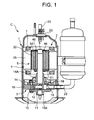
- FIG. 1 is a vertical side view of a compressor C to which a rotor of an electric motor of the present invention is applied.
- reference numeral 1 is a sealed container.
- An electric motor (a brushless DC motor) 2 is received on the upside in the container, and a compression element 3 driven and rotated by the electric motor 2 is received on the downside in the container.
- the sealed container 1 is beforehand divided into two parts where the electric motor 2 and the compression element 3 are received, and then hermetically closed by high-frequency sealing.
- the present embodiment will be described by use of a rotary compressor as the compressor C, but the present invention is not limited to the compressor, and is effective even in a case where, for example, a reciprocating or scroll type compressor or the like is used.
- the electric motor 2 is constituted of a stator 4 attached to an inner wall of the sealed container 1, and a rotor 5 disposed on the inner side of the stator 4 and supported rotatably around a rotary shaft 6. It is to be noted that in the electric motor 2 of the present embodiment, a four-pole permanent magnet rotary type electric motor is used in which a ratio between the number of poles of the rotor 5 and the number of slots of the stator 4 is 2:3.
- the stator 4 is constituted of a stator core 25 having a constitution in which electromagnetic steel plates are laminated, and a stator coil 7 (not shown in FIG. 2 ) wound around the stator core 25.
- the stator core 25 is provided with tooth portions 26 each having a predetermined width, and the tip of each of the tooth portions 26 is extended to both arms, thereby forming a tooth tip portion 27 along the surface of the rotor 5.
- the stator coil 7 for excitation is directly wound around each tooth portion 26 by use of a space of a slot portion 28, and magnetic poles of the stator 4 are formed by a concentrated direct winding system.
- the stator coil 7 has a three-phase constitution of U, V and W-phases.
- the compression element 3 is constituted of a cylinder 10 in which a compression chamber is formed; a roller 12 fitted into an eccentric portion 11 provided on the rotary shaft 6 to eccentrically rotate in the cylinder 10; a vane (not shown) which abuts on the roller 12 to partition the compression chamber of the cylinder 10 into a low pressure chamber side and a high pressure chamber side; an upper support member 14 which closes the open surface of the cylinder 10 on one side thereof (the upside in FIG. 1 ) and which is also used as a bearing 14A of the rotary shaft 6; and a lower support member 15 which closes the open surface of the cylinder on the other side thereof (the downside in FIG. 1 ) and which is also used as a bearing 15A of the rotary shaft 6.
- reference numeral 17 is a discharge muffler chamber.
- This discharge muffler chamber 17 is formed by covering a part of the upper support member 14 on the side of the electric motor 2 (the upside) with a cover 18.
- the inside of the discharge muffler chamber 17 is connected to the high pressure chamber side of the cylinder 10 via a discharge port 19.
- the cover 18 is provided with a communication hole (not shown) which connects the inside of the discharge muffler chamber 17 to the inside of the sealed container 1, and a refrigerant in the discharge muffler chamber 17 is discharged into the sealed container 1 through the communication hole.
- reference numeral 20 is a refrigerant discharge tube for discharging, to the outside of the compressor C, a high-temperature high-pressure refrigerant gas discharged into the sealed container 1.
- the refrigerant discharge tube is attached to the upper end of the sealed container 1.
- Reference numeral 22 is a refrigerant introducing tube for introducing a low-temperature low-pressure refrigerant into the cylinder 10 from the outside of the compressor C.
- reference numeral 23 is a terminal for supplying a power from the outside of the sealed container 1 to the stator coil 7 of the stator 4, and the terminal is attached around the center of the upper end of the sealed container 1. The terminal 23 is connected to the stator coil 7 via a lead wire (not shown).
- FIG. 3 is a plan view of the rotor 5 of one embodiment to which the present invention is applied (a state before permanent magnets are inserted), and FIG. 4 is a side view of the rotor 5 of FIG. 3 .
- reference numeral 30 is a rotor core. Electromagnetic steel plates having thicknesses of 0.35 mm to 0.50 mm are punched into a shape shown in FIG. 3 , and a plurality of resultant rotor iron plates 31 are stacked, mutually caulked and integrally laminated. If the thickness of the rotor iron plate 31 is excessively increased, a problem occurs that an eddy current loss increases. This eddy current loss is a loss caused by the generation of the current based on the variance of a magnetic flux in the core 30. The eddy current loss can be decreased by decreasing the thickness of the core 30.
- the thickness of the rotor iron plate 31 is excessively decreased, it becomes difficult to process the plate, or a problem occurs that processability and processing precision lower. In consideration of such problems, it is preferable to use the rotor iron plate 31 having a thickness of 0.35 mm to 0.50 mm as described above, and in the present embodiment, the rotor iron plate 31 having a thickness of 0.35 mm is used.
- the insertion holes 32 to 35 are provided along the axial direction of the rotary shaft 6.
- the insertion holes 32 to 35 are formed into such a V-shape as to project toward the outer periphery of the rotor core 30.
- the insertion holes 32 to 35 are formed so that centers (hereinafter referred to as the outer ends) 32C to 35C are positioned on the most distant outer peripheral side when seen from a rotary shaft 6 side and so that each insertion hole extends to both sides so as to tilt inwardly (the rotary shaft 6 side) from each of the outer ends 32C to 35C symmetrically with respect to a straight line (e.g., a broken line L) connecting the axial center of the rotary shaft 6 to each of the outer ends 32C to 35C.
- a straight line e.g., a broken line L
- an angle ⁇ formed by tips (e.g., 32E, 32E) of each of the insertion holes 32 to 35 and the outer end thereof (32C) is a predetermined obtuse angle, and the whole insertion hole has a substantially rectangular shape (V-shape).
- a pair of flat plate-like permanent magnets 37 to 44 which are rare earth magnets are inserted into the insertion holes 32 to 35, respectively.
- four pairs of permanent magnets are provided. Specifically, two permanent magnets 37, 38 forming a pair are inserted into the insertion hole 32, two permanent magnets 39, 40 forming a pair are inserted into the insertion hole 33, two permanent magnets 41, 42 forming a pair are inserted into the insertion hole 34, and two permanent magnets 43, 44 forming a pair are inserted into the insertion hole 35, thereby constituting magnetic poles, respectively.
- the outer peripheral surface of the rotor core 30 in front of the magnetic pole in a rotating direction thereof is provided with cutout portions S, respectively.
- reference numerals 45 are through holes into which rivets 46 for integrally combining, with the rotor core 30, nonmagnetic end face members 50, 51 attached to both end faces of the rotor core 30 are inserted, and reference numerals 47 are air holes.
- the rotor 5 is provided with four through holes 45 and four air holes 47, and these holes are alternately provided with a substantially equal interval and at a substantially equal radius from the rotary shaft 6 as the center.
- the positions and numbers of the through holes 45 and the air holes 47 are preferably appropriately determined in consideration of the arrangement of the permanent magnets 37 to 44 or the like so that characteristics and efficiency do not lower, and the present invention is not limited to the arrangement and the numbers of the present embodiment.
- FIG. 5 is a partially enlarged view around the insertion hole 32 of the rotor 5 in a state where the permanent magnets 37 to 44 are inserted into the insertion holes 32 to 35, respectively.
- the insertion hole 32 constituting one of the four magnetic poles of the rotor 5 and the pair of permanent magnets 37, 38 inserted into the insertion hole 32 will be described, and the description of the other insertion holes 33 to 35 and permanent magnets 39 to 44 inserted into the insertion holes 33 to 35 is omitted.
- the insertion holes 33 to 35 and the permanent magnets 39 to 44 have constitutions and arrangements similar to those of the insertion hole 32 and the permanent magnets 37, 38.
- reference numerals 55, 55 are holes formed so as to extend through the plurality of rotor iron plates 31 positioned at both end faces of the rotor 5, and connected to the insertion hole 32.
- Reference numerals 56, 56 are thin fixing members provided between the holes 55 and 55 and the insertion hole 32 and configured to fix the permanent magnets 37, 38, respectively. It is to be noted that in FIG. 3 , these holes 55 and the fixing members 56 are omitted, but the plurality of rotor iron plates 31 positioned at both the end faces of the rotor 5 are provided with the holes 55 connected to the insertion holes 33 to 35 in the same manner as in the insertion hole 32, and the fixing members 56.
- the fixing members 56 are pressed from the holes 55 toward the permanent magnets 37 to 44 (i.e., from the rotary shaft 6 side to the outer peripheral side of the rotary shaft), whereby both upper and lower ends of each permanent magnet can be held by the fixing members 56 and the inner walls of the insertion holes 32 to 35.
- the end face members 50, 51 are attached to both the end faces of the rotor 5, and are integrally combined by the rivets 46.
- the fixing members 56 are pressed from the holes 55 toward the permanent magnets 37 to 44 and held, but the present invention is not limited to this embodiment.
- the fixing members may be projected into the insertion holes 32 to 35, and the permanent magnets 37 to 44 may be pressed into the insertion holes 32 to 35, respectively.
- FIG. 6 is an enlarged view of a broken line part of FIG. 5 .
- an angle ⁇ at which a center line 37C of one permanent magnet 37 of the pair of permanent magnets inserted into the insertion hole 32 in a width direction intersects with a center line 38C of the other permanent magnet 38 in the width direction is substantially equal to an angle ⁇ (the above predetermined obtuse angle) formed by the tips 32E, 32E of the insertion hole 32 and the outer end 32C of the insertion hole.
- the insertion hole 32 is formed so as to satisfy the following formula (1), in which t1 is the shortest distance from the outer end 32C of the insertion hole 32 (i.e., P1 shown in FIG. 6 ) to an outer periphery P2 of the rotor core 30 and t2 is the width dimension of the permanent magnet. It is to be noted that as shown in FIG. 6 , in the present embodiment, the outer end P1 of the insertion hole 32, the outer periphery P2 of the rotor core 30 and an axial center P6 of the rotary shaft 6 are present on substantially the same straight line L. 0 ⁇ t ⁇ 1 / t ⁇ 2 ⁇ 0.15
- FIG. 7 shows the variance of the vibration value of the stator core with respect to t1/t2. It is seen from FIG. 7 that when the value of t1/t2 is 0.15 or less, the vibration value of the stator core 25 moderately increases with the increase of t1/t2 but that when the value of t1/t2 is larger than 0.15, the vibration value rapidly increases.
- the insertion hole into which the pair of permanent magnets are inserted and the respective permanent magnets are arranged so that the vibration value of the stator core is smaller than that of an inflection point at which the moderate increase of the vibration value of the stator core changes to the rapid increase thereof, that is, so that the above formula (1) is satisfied.
- the insertion holes 32 to 35 and the pair of permanent magnets have a constitution which satisfies the following formulas (2), (3) in addition to the above formula (1). 0.35 mm ⁇ t ⁇ 1 ⁇ 1.80 mm 12 mm ⁇ t ⁇ 2 ⁇ 15 mm
- the lower limit value (i.e., 0.35 mm) of t1 shown in the above formula (2) is based on the dimension (the thickness) of each rotor iron plate 31 constituting the rotor core 30 in a rotary shaft 6 direction. That is, the magnetic flux preferably stepwise passes through the rotor core 30, as t1 is small (i.e., the variance ratio of the magnetic force line flowing through the rotor core 30 decreases).
- the lower limit value is smaller than the dimension of the rotor iron plate 31 constituting the rotor core 30 in the rotary shaft 6 direction, processing precision extremely lowers. Therefore, from the viewpoint of this problem of the processing precision, the value cannot be smaller than the dimension of the rotor iron plate 31 in the rotary shaft 6 direction.
- t1 is also set to 0.35 mm or more.
- an upper limit value i.e., 15 mm
- a lower limit value i.e., 12 mm
- the iron loss of the rotor core 30 increases, and efficiency disadvantageously remarkably deteriorates.
- FIG. 8 is a diagram showing the positions of the permanent magnets 37 to 44 in the stator 4 at the respective rotation angles of the rotor 5 in the present embodiment
- FIG. 9 is a diagram showing magnetic fluxes at the respective rotation angles shown in FIG. 8
- FIG. 10 is a partially enlarged view of FIG. 9 .
- the stator coil 7 of the U-phase is directly wound around tooth portions 26A, 26D of the stator core 25
- the coil of the V-phase is directly wound around tooth portions 26B, 26E
- the coil of the W-phase is directly wound around tooth portions 26C, 26F.
- an arrangement shown in (1) corresponds to a rotation angle of 0 degree of the rotor 5
- (2) shows that the rotor 5 has been rotated from (1) in an arrow direction
- (3) shows that the rotor 5 has further been rotated as much as 15 degrees from (2) (the rotor 5 has been rotated as much as 30 degrees from (1)).
- the insertion holes 32 to 35 are omitted.
- the right column shows the rotor 5 of the embodiment to which the present invention is applied
- the left column shows a rotor 205 having a conventional structure.
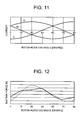
- FIG. 11 is a diagram showing a three-phase sinusoidal wave, and in this case, FIG. 12 shows the variance of a suction force generated between the tooth portion 26 of the stator core 25 and the permanent magnets of the rotor 5 (a broken line shows that the conventional rotor 205 is used, and a solid line shows that the rotor 5 of the present embodiment is used).
- FIG. 12 shows that in the structure of the embodiment in which the present invention is employed, it has been seen that the maximum value of the suction force decreases and the minimum value of the suction force increases as compared with the conventional structure. Therefore, it has been obvious from FIG. 12 that the variance of the suction force decreases in the present embodiment as compared with the conventional structure.
- the suction force periodically applied in a concentrated manner can be decreased, thereby decreasing the variance of the suction force.
- the deformation of the stator core 25 can be suppressed, and the generation of noises generated by the deformation can effectively be suppressed.
- the above invention is effective in a case where the permanent magnets 37 to 44 are rare earth magnets. That is, the rare earth magnets increase material cost and processing cost, and are used mainly in a planar shape (a flat plate-like shape). Therefore, the above invention is especially effective in a case where the permanent magnets 37 to 44 are the rare earth magnets.
- the rare earth permanent magnet has a magnet holding force larger than that of a ferrite permanent magnet having the same shape, and hence has problems that excitation of the stator due to the suction force increases and that the vibration is transmitted to a surrounding area, thereby increasing noises.
- such a noise problem can effectively be suppressed.
- the variance of the magnetic force line can be optimized, and the vibration of the stator 4 can be decreased.
- each insertion hole (32) into which a pair of permanent magnets (e.g., permanent magnets 37, 38) constituting one magnetic pole are inserted is formed into such a V-shape as to project toward the outer periphery of the rotor core 30 as shown in FIG. 4 , but the insertion holes of the present invention are not limited to this embodiment, and an insertion hole used exclusively for each permanent magnet may be formed.
- FIG. 13 is a partially enlarged view of a rotor for explaining one example of this case.
- One magnetic pole of four magnetic poles of the rotor is provided with a pair of insertion holes 37A, 38A, and the pair of insertion holes 37A, 38A are disposed in the form of a slanted roof when seen from the side of a rotary shaft 6.
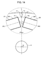
- FIG. 14 is an enlarged view of a broken line part of FIG. 13 . It is to be noted that in FIGS. 13 and 14 , the same reference numerals as those of FIGS. 1 to 12 indicate the same or similar functions or effects, and hence the description thereof is omitted.
- the insertion holes 37A, 38A have such a constitution as to satisfy the above formula (1), in which t1 is the shortest distance from a center P5 of a line L1 connecting outer ends P3, P4 of the adjacent insertion holes 37A, 38A to an outer periphery P2 of a rotor core 30 and t2 is the width dimension of each of the permanent magnets 37, 38. It is to be noted that as shown in FIG.
- the center P5 of the line L1 connecting the outer ends P3, P4 of the adjacent insertion holes 37A, 38A, the outer periphery P2 of the rotor core 30 and the axial center P6 of the rotary shaft 6 are present along the same straight line L, and the line L1 crosses the line L passing through the axial center P6 of the rotary shaft 6 and the center P5 of the line L1 at right angles.
- magnetic force lines generated by the permanent magnets 37 to 44 can be scattered in the same manner as in Embodiment 1 described above. Moreover, a distance from the adjacent outer ends of the pair of permanent magnets inserted into the insertion holes to the outer periphery of the rotor core can be shortened, whereby the variance ratio of the magnetic force line flowing through the rotor core 30 can be decreased. In consequence, a suction force periodically applied in a concentrated manner can be decreased, thereby decreasing the variance of the suction force, whereby the deformation of the stator core 25 can be suppressed, and the generation of the noises by the deformation can effectively be suppressed.
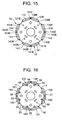
- the shape of the insertion hole is not limited to a shape shown in FIGS. 13 and 14 , and as shown in FIGS. 15 and 16 , the widths of both ends 137E, 137E to 144E, 144E of insertion holes 137 to 144 used exclusively for the permanent magnets on the side of the rotary shaft 6 may be decreased.
- reference numerals 55 shown in FIG. 16 are holes formed so as to extend through a plurality of rotor iron plates 31 positioned at both end faces of the rotor 5 and connected to the insertion holes 137 to 144 in the same manner as in the holes 55 described above with reference to FIGS. 5 and 13 .
- Reference numerals 56 are thin fixing members provided between the holes 55 and the insertion holes 137 to 144 and configured to fix the permanent magnets 37 to 44 inserted into the insertion holes 137 to 144, respectively, in the same manner as in the fixing members 56 shown in FIG. 5 .
- a method for fixing the permanent magnets 37 to 44 by the fixing members 56 is described above, and hence the description thereof is omitted here.
- a four-pole permanent magnet rotary type electric motor is used in which a ratio between the number of poles of a rotor 5 and the number of slots of a stator 4 is 2:3.
- a six-pole permanent magnet rotary type electric motor may be used in which a ratio between the number of poles of a rotor 105 and the number of slots of a stator 104 is 2:3.
- the rotor 105 is provided with insertion holes 106 to 111 which have a rectangular shape and into which each pair of permanent magnets are inserted.
- the insertion holes 106 to 111 are provided along the axial direction of a rotary shaft 6, and are formed so that the center of each of the insertion holes 106 to 111 is positioned on the most distant outer peripheral side from the rotary shaft 6 side and so that each hole extends to both sides symmetrically with respect to a straight line (e.g., a broken line L) connecting the center of the insertion hole and the center (the axial center) of the rotary shaft 6.
- a straight line e.g., a broken line L
- stator coils 7 of U-phase, V-phase and W-phase are successively directly wound around tooth portions 26 shown in FIG. 18 , and a current is caused to flow through the wound stator coils 7 in order, whereby a driving force can be generated by an interaction of a varying magnetic field of the current and a magnetic field generated by permanent magnets (not shown) of the rotor 105.
Landscapes
- Engineering & Computer Science (AREA)
- Power Engineering (AREA)
- Permanent Field Magnets Of Synchronous Machinery (AREA)
- Iron Core Of Rotating Electric Machines (AREA)
Abstract
Description
- The present invention relates to a structure of a rotor of an electric motor used for a compressor or the like.
- Heretofore, this type of electric motor for the compressor is constituted of a ring-shaped stator attached to an inner wall of a sealed container and a rotor disposed on the inner side of the stator. This stator has, for example, a constitution in which stator coils of three phases of U, V and W-phases are directly wound around tooth portions of a stator core formed by laminating a plurality of electromagnetic steel plates.
- Moreover, the rotor has a constitution in which a plurality of iron plates for the rotor are laminated and fixed by caulking, thereby forming a rotor core. Furthermore, permanent magnets constituting magnetic poles are inserted into insertion holes formed along the outer peripheral side of this rotor core. In addition, a current is caused to flow through the three-phase stator coils wound around the tooth portions of the stator in order, and a driving force is generated by an interaction between a varying magnetic field of the current and a magnetic field of the permanent magnets (e.g., see Japanese Patent Application Laid-Open No.
2007-174776 2008-022666 - However, in such an electric motor, heretofore, it has been known that a magnetic flux noticeably varies with respect to the rotation of the rotor and that a large suction force is periodically generated between the tooth portions of the stator core and the magnets of the rotor. Such a large suction force generated periodically has caused a problem that the stator core is deformed, thereby generating noises.
- The present invention has been developed to solve such a conventional technical problem, and an object thereof is to provide a rotor of an electric motor which can decrease the generation of noises.
- That is, according to a first aspect of the present invention, there is provided a rotor of an electric motor, comprising: a rotor core formed by laminating a plurality of iron plates for the rotor; a pair of insertion holes corresponding to each magnetic pole of the rotor core and provided along the axial direction of a rotary shaft; and a pair of flat plate-like permanent magnets inserted into the insertion holes to constitute the magnetic pole, wherein the pair of insertion holes are disposed in the form of a slanted roof when seen from the side of the rotary shaft, and 0 < t1/t2 ≤ 0.15 is satisfied in which t1 is the shortest distance from the center of a line connecting outer ends of the adjacent insertion holes to the outer periphery of the rotor core and t2 is a width dimension of each of the permanent magnets.
- According to a second aspect of the present invention, there is provided a rotor of an electric motor, comprising: a rotor core formed by laminating a plurality of iron plates for the rotor; insertion holes corresponding to magnetic poles of the rotor core and provided along the axial direction of a rotary shaft; and a pair of flat plate-like permanent magnets inserted into each of the insertion holes to constitute the magnetic pole, wherein the insertion holes are formed into such a V-shape as to project toward the outer periphery of the rotor core, and 0 < t1/t2 ≤ 0.15 is satisfied in which t1 is the shortest distance from the outer end of the insertion hole to the outer periphery of the rotor core and t2 is a width dimension of each of the permanent magnets.
- The rotor of the electric motor of a third aspect of the present invention is characterized in that in the above aspects of the present invention, the permanent magnets are rare earth magnets.
- The rotor of the electric motor of a fourth aspect of the present invention is characterized in that in any one of the first to third aspects of the present invention, the outer peripheral surface of the rotor core in front of the magnetic pole in a rotating direction thereof is provided with cutout portions.
- According to the first aspect of the present invention, in the rotor of the electric motor, comprising the rotor core formed by laminating the plurality of iron plates for the rotor, the pair of insertion holes corresponding to the magnetic pole of the rotor core and provided along the axial direction of the rotary shaft and the pair of flat plate-like permanent magnets inserted into the insertion holes to constitute the magnetic pole, the pair of insertion holes are disposed in the form of the slanted roof when seen from the side of the rotary shaft. Therefore, the pair of permanent magnets can be disposed in the pair of insertion holes in the form of the slanted roof when seen from the side of the rotary shaft, and magnetic force lines generated by the permanent magnets can be scattered. In particular, in the case of 0 < t1/t2 ≤ 0.15 in which t1 is the shortest distance from the center of the line connecting the outer ends of the adjacent insertion holes to the outer periphery of the rotor core and t2 is the width dimension of each of the permanent magnets, a distance from the adjacent outer ends of the pair of permanent magnets inserted into the insertion holes to the outer periphery of the rotor core can be shortened, whereby the variance ratio of the magnetic force line flowing through the rotor core can be decreased.
- In consequence, a suction force periodically applied in a concentrated manner can be decreased, and the variance of the suction force can be decreased, whereby the deformation of a stator core can be suppressed, and the generation of noises due to the deformation can effectively be suppressed.
- According to the second aspect of the present invention, in the rotor of the electric motor, comprising the rotor core formed by laminating the plurality of iron plates for the rotor, the insertion holes corresponding to the magnetic poles of this rotor core and provided along the axial direction of the rotary shaft and the pair of flat plate-like permanent magnets inserted into each of the insertion holes to constitute the magnetic pole, the insertion holes are formed into such a V-shape as to project toward the outer periphery of the rotor core. Therefore, the pair of permanent magnets can be disposed in each insertion hole in the form of the slanted roof when seen from the side of the rotary shaft, and magnetic force lines generated by the permanent magnets can be scattered. In particular, in the case of 0 < t1/t2 ≤ 0.15 in which t1 is the shortest distance from the outer end of the insertion hole to the outer periphery of the rotor core and t2 is the width dimension of each of the permanent magnets, a distance from adjacent outer ends of the pair of permanent magnets inserted into the insertion holes to the outer periphery of the rotor core can be shortened, whereby the variance ratio of the magnetic force line flowing through the rotor core can be decreased.
- In consequence, a suction force periodically applied in a concentrated manner can be decreased, and the variance of the suction force can be decreased, whereby the deformation of a stator core can be suppressed, and the generation of noises due to the deformation can effectively be suppressed.
- In particular, the above aspects of the present invention are effective in a case where as in the third aspect of the present invention, the permanent magnets are the rare earth magnets having high material cost and processing cost and formed mainly into a planar shape. Furthermore, in the rare earth permanent magnets, the holding force of the magnets increases, and the excitation of a stator due to the suction force increases as compared with ferrite permanent magnets. Therefore, the permanent magnets have a problem that the vibration thereof is transmitted to a surrounding area, thereby increasing the noises. However, according to the first or second aspect of the present invention, the problem of the noises can be suppressed. Therefore, the first or second aspect of the present invention becomes more valid and effective in a case where the permanent magnets are the rare earth magnets as in the third aspect of the present invention.
- Furthermore, when the outer peripheral surface of the rotor core in front of the magnetic pole in the rotating direction thereof is provided with cutout portions as in the fourth aspect of the present invention, the variance of the magnetic force line can be optimized, and the vibration of the stator can be decreased.
-
-
FIG. 1 is a vertical side view of a compressor to which the present invention is applied; -
FIG. 2 is a plan view of a stator core of a stator of an electric motor ofFIG. 1 ; -
FIG. 3 is a plan view of a rotor according to one embodiment of the present invention (Embodiment 1); -
FIG. 4 is a side view of the rotor ofFIG. 3 ; -
FIG. 5 is a partially enlarged view in a state where permanent magnets are inserted into an insertion hole of the rotor ofFIG. 3 ; -
FIG. 6 is an enlarged view of a broken line part ofFIG. 5 ; -
FIG. 7 is a diagram showing the variance of the vibration value of the stator core with respect to (t1/t2); -
FIG. 8 is a diagram showing positional relations between a stator and the permanent magnets of the rotor at rotation angles; -
FIG. 9 is a diagram showing magnetic fluxes of an electric motor comprising a conventional rotor and an electric motor comprising a rotor of the present invention at the rotation angles ofFIG. 8 ; -
FIG. 10 is a partially enlarged view ofFIG. 9 ; -
FIG. 11 is a diagram showing a three-phase sinusoidal wave; -
FIG. 12 is a diagram showing the variance of a suction force; -
FIG. 13 is a partially enlarged view of another rotor provided with insertion holes having a shape different from that ofFIG. 3 ; -
FIG. 14 is an enlarged view of a broken line part ofFIG. 13 ; -
FIG. 15 is a plan view showing one example of a rotor provided with insertion holes having a shape different from that ofFIG. 13 ; -
FIG. 16 is a plan view showing another example of the rotor provided with the insertion holes having the shape different from that ofFIG. 13 ; -
FIG. 17 is a plan view of a rotor of another embodiment (Embodiment 2); and -
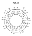
FIG. 18 is a plan view of a stator corresponding to the rotor ofFIG. 16 . - Hereinafter, embodiments of the present invention will be described in detail with reference to the drawings.
-
FIG. 1 is a vertical side view of a compressor C to which a rotor of an electric motor of the present invention is applied. InFIG. 1 ,reference numeral 1 is a sealed container. An electric motor (a brushless DC motor) 2 is received on the upside in the container, and acompression element 3 driven and rotated by theelectric motor 2 is received on the downside in the container. The sealedcontainer 1 is beforehand divided into two parts where theelectric motor 2 and thecompression element 3 are received, and then hermetically closed by high-frequency sealing. It is to be noted that the present embodiment will be described by use of a rotary compressor as the compressor C, but the present invention is not limited to the compressor, and is effective even in a case where, for example, a reciprocating or scroll type compressor or the like is used. - The
electric motor 2 is constituted of astator 4 attached to an inner wall of the sealedcontainer 1, and arotor 5 disposed on the inner side of thestator 4 and supported rotatably around arotary shaft 6. It is to be noted that in theelectric motor 2 of the present embodiment, a four-pole permanent magnet rotary type electric motor is used in which a ratio between the number of poles of therotor 5 and the number of slots of thestator 4 is 2:3. - As shown in
FIG. 2 , thestator 4 is constituted of astator core 25 having a constitution in which electromagnetic steel plates are laminated, and a stator coil 7 (not shown inFIG. 2 ) wound around thestator core 25. Specifically, thestator core 25 is provided withtooth portions 26 each having a predetermined width, and the tip of each of thetooth portions 26 is extended to both arms, thereby forming atooth tip portion 27 along the surface of therotor 5. Thestator coil 7 for excitation is directly wound around eachtooth portion 26 by use of a space of aslot portion 28, and magnetic poles of thestator 4 are formed by a concentrated direct winding system. Thestator coil 7 has a three-phase constitution of U, V and W-phases. - On the other hand, the
compression element 3 is constituted of acylinder 10 in which a compression chamber is formed; aroller 12 fitted into aneccentric portion 11 provided on therotary shaft 6 to eccentrically rotate in thecylinder 10; a vane (not shown) which abuts on theroller 12 to partition the compression chamber of thecylinder 10 into a low pressure chamber side and a high pressure chamber side; anupper support member 14 which closes the open surface of thecylinder 10 on one side thereof (the upside inFIG. 1 ) and which is also used as abearing 14A of therotary shaft 6; and alower support member 15 which closes the open surface of the cylinder on the other side thereof (the downside inFIG. 1 ) and which is also used as abearing 15A of therotary shaft 6. - In
FIG. 1 , reference numeral 17 is a discharge muffler chamber. This discharge muffler chamber 17 is formed by covering a part of theupper support member 14 on the side of the electric motor 2 (the upside) with acover 18. The inside of the discharge muffler chamber 17 is connected to the high pressure chamber side of thecylinder 10 via adischarge port 19. Moreover, thecover 18 is provided with a communication hole (not shown) which connects the inside of the discharge muffler chamber 17 to the inside of the sealedcontainer 1, and a refrigerant in the discharge muffler chamber 17 is discharged into the sealedcontainer 1 through the communication hole. - Moreover,
reference numeral 20 is a refrigerant discharge tube for discharging, to the outside of the compressor C, a high-temperature high-pressure refrigerant gas discharged into the sealedcontainer 1. The refrigerant discharge tube is attached to the upper end of the sealedcontainer 1.Reference numeral 22 is a refrigerant introducing tube for introducing a low-temperature low-pressure refrigerant into thecylinder 10 from the outside of the compressor C. Moreover,reference numeral 23 is a terminal for supplying a power from the outside of the sealedcontainer 1 to thestator coil 7 of thestator 4, and the terminal is attached around the center of the upper end of the sealedcontainer 1. The terminal 23 is connected to thestator coil 7 via a lead wire (not shown). - Next, the
rotor 5 of theelectric motor 2 will be described in detail.FIG. 3 is a plan view of therotor 5 of one embodiment to which the present invention is applied (a state before permanent magnets are inserted), andFIG. 4 is a side view of therotor 5 ofFIG. 3 . - In the drawing,
reference numeral 30 is a rotor core. Electromagnetic steel plates having thicknesses of 0.35 mm to 0.50 mm are punched into a shape shown inFIG. 3 , and a plurality of resultantrotor iron plates 31 are stacked, mutually caulked and integrally laminated. If the thickness of therotor iron plate 31 is excessively increased, a problem occurs that an eddy current loss increases. This eddy current loss is a loss caused by the generation of the current based on the variance of a magnetic flux in thecore 30. The eddy current loss can be decreased by decreasing the thickness of thecore 30. However, if the thickness of therotor iron plate 31 is excessively decreased, it becomes difficult to process the plate, or a problem occurs that processability and processing precision lower. In consideration of such problems, it is preferable to use therotor iron plate 31 having a thickness of 0.35 mm to 0.50 mm as described above, and in the present embodiment, therotor iron plate 31 having a thickness of 0.35 mm is used. - Moreover, in the present embodiment, since the four-
pole rotor 5 is employed as described above, as shown inFIG. 3 , fourinsertion holes 32 to 35 corresponding to the magnetic poles of therotor core 30 are formed in therotor iron plate 31 by punching. - As shown in
FIG. 5 , the insertion holes 32 to 35 are provided along the axial direction of therotary shaft 6. The insertion holes 32 to 35 are formed into such a V-shape as to project toward the outer periphery of therotor core 30. Specifically, the insertion holes 32 to 35 are formed so that centers (hereinafter referred to as the outer ends) 32C to 35C are positioned on the most distant outer peripheral side when seen from arotary shaft 6 side and so that each insertion hole extends to both sides so as to tilt inwardly (therotary shaft 6 side) from each of the outer ends 32C to 35C symmetrically with respect to a straight line (e.g., a broken line L) connecting the axial center of therotary shaft 6 to each of the outer ends 32C to 35C. In consequence, an angle α formed by tips (e.g., 32E, 32E) of each of the insertion holes 32 to 35 and the outer end thereof (32C) is a predetermined obtuse angle, and the whole insertion hole has a substantially rectangular shape (V-shape). - A pair of flat plate-like
permanent magnets 37 to 44 which are rare earth magnets are inserted into the insertion holes 32 to 35, respectively. In the present embodiment, since the four-pole rotor 5 is employed as described above, four pairs of permanent magnets are provided. Specifically, twopermanent magnets insertion hole 32, twopermanent magnets insertion hole 33, twopermanent magnets insertion hole 34, and twopermanent magnets insertion hole 35, thereby constituting magnetic poles, respectively. - Moreover, as shown in
FIG. 3 , in therotor 5, the outer peripheral surface of therotor core 30 in front of the magnetic pole in a rotating direction thereof is provided with cutout portions S, respectively. - It is to be noted that in
FIG. 3 ,reference numerals 45 are through holes into which rivets 46 for integrally combining, with therotor core 30, nonmagneticend face members rotor core 30 are inserted, andreference numerals 47 are air holes. In the present embodiment, as shown inFIG. 3 , therotor 5 is provided with four throughholes 45 and fourair holes 47, and these holes are alternately provided with a substantially equal interval and at a substantially equal radius from therotary shaft 6 as the center. However, the positions and numbers of the throughholes 45 and the air holes 47 are preferably appropriately determined in consideration of the arrangement of thepermanent magnets 37 to 44 or the like so that characteristics and efficiency do not lower, and the present invention is not limited to the arrangement and the numbers of the present embodiment. - Here, attention is focused on one of four magnetic poles of the
rotor 5, and the insertion hole into which the pair of permanent magnets are inserted and the permanent magnets inserted into this insertion hole will be described in detail.FIG. 5 is a partially enlarged view around theinsertion hole 32 of therotor 5 in a state where thepermanent magnets 37 to 44 are inserted into the insertion holes 32 to 35, respectively. It is to be noted that here, as shown inFIG. 5 , theinsertion hole 32 constituting one of the four magnetic poles of therotor 5 and the pair ofpermanent magnets insertion hole 32 will be described, and the description of the other insertion holes 33 to 35 andpermanent magnets 39 to 44 inserted into the insertion holes 33 to 35 is omitted. However, the insertion holes 33 to 35 and thepermanent magnets 39 to 44 have constitutions and arrangements similar to those of theinsertion hole 32 and thepermanent magnets - In
FIG. 5 ,reference numerals rotor iron plates 31 positioned at both end faces of therotor 5, and connected to theinsertion hole 32.Reference numerals holes insertion hole 32 and configured to fix thepermanent magnets FIG. 3 , theseholes 55 and the fixingmembers 56 are omitted, but the plurality ofrotor iron plates 31 positioned at both the end faces of therotor 5 are provided with theholes 55 connected to the insertion holes 33 to 35 in the same manner as in theinsertion hole 32, and the fixingmembers 56. - According to such a constitution, after inserting the
permanent magnets 37 to 44 into the insertion holes 32 to 35, the fixingmembers 56 are pressed from theholes 55 toward thepermanent magnets 37 to 44 (i.e., from therotary shaft 6 side to the outer peripheral side of the rotary shaft), whereby both upper and lower ends of each permanent magnet can be held by the fixingmembers 56 and the inner walls of the insertion holes 32 to 35. Afterward, theend face members rotor 5, and are integrally combined by therivets 46. It is to be noted that in the present embodiment, as described above, after inserting thepermanent magnets 37 to 44 into the insertion holes 32 to 35, the fixingmembers 56 are pressed from theholes 55 toward thepermanent magnets 37 to 44 and held, but the present invention is not limited to this embodiment. For example, the fixing members may be projected into the insertion holes 32 to 35, and thepermanent magnets 37 to 44 may be pressed into the insertion holes 32 to 35, respectively. - On the other hand,
FIG. 6 is an enlarged view of a broken line part ofFIG. 5 . As shown inFIGS. 5 and6 , an angle β at which acenter line 37C of onepermanent magnet 37 of the pair of permanent magnets inserted into theinsertion hole 32 in a width direction intersects with acenter line 38C of the otherpermanent magnet 38 in the width direction is substantially equal to an angle α (the above predetermined obtuse angle) formed by thetips insertion hole 32 and theouter end 32C of the insertion hole. - In this case, the
insertion hole 32 is formed so as to satisfy the following formula (1), in which t1 is the shortest distance from theouter end 32C of the insertion hole 32 (i.e., P1 shown inFIG. 6 ) to an outer periphery P2 of therotor core 30 and t2 is the width dimension of the permanent magnet. It is to be noted that as shown inFIG. 6 , in the present embodiment, the outer end P1 of theinsertion hole 32, the outer periphery P2 of therotor core 30 and an axial center P6 of therotary shaft 6 are present on substantially the same straight line L.
-
FIG. 7 shows the variance of the vibration value of the stator core with respect to t1/t2. It is seen fromFIG. 7 that when the value of t1/t2 is 0.15 or less, the vibration value of thestator core 25 moderately increases with the increase of t1/t2 but that when the value of t1/t2 is larger than 0.15, the vibration value rapidly increases. To solve the problem, in the present invention, the insertion hole into which the pair of permanent magnets are inserted and the respective permanent magnets, that is, the insertion holes 32 to 35 and thepermanent magnets 37 to 44 are arranged so that the vibration value of the stator core is smaller than that of an inflection point at which the moderate increase of the vibration value of the stator core changes to the rapid increase thereof, that is, so that the above formula (1) is satisfied. - In particular, according to the present embodiment, the insertion holes 32 to 35 and the pair of permanent magnets have a constitution which satisfies the following formulas (2), (3) in addition to the above formula (1).


- The lower limit value (i.e., 0.35 mm) of t1 shown in the above formula (2) is based on the dimension (the thickness) of each
rotor iron plate 31 constituting therotor core 30 in arotary shaft 6 direction. That is, the magnetic flux preferably stepwise passes through therotor core 30, as t1 is small (i.e., the variance ratio of the magnetic force line flowing through therotor core 30 decreases). However, when the lower limit value is smaller than the dimension of therotor iron plate 31 constituting therotor core 30 in therotary shaft 6 direction, processing precision extremely lowers. Therefore, from the viewpoint of this problem of the processing precision, the value cannot be smaller than the dimension of therotor iron plate 31 in therotary shaft 6 direction. In the present embodiment, since therotor iron plate 31 having a dimension of 0.35 mm in therotary shaft 6 direction is used as described above, t1 is also set to 0.35 mm or more. - Moreover, as to t2 shown in the above formula (3), an upper limit value (i.e., 15 mm) is determined from the problem of the iron loss of the
rotor core 30, and a lower limit value (i.e., 12 mm) is determined from the problem of the magnetic flux. Specifically, when t2 is larger than 15 mm, the iron loss of therotor core 30 increases, and efficiency disadvantageously remarkably deteriorates. - Moreover, when the value is smaller than t2, the above iron loss decreases. However, when the value is smaller than 12 mm, the magnetic flux (the magnetic force line) excessively decreases. Also in this case, there occurs a problem that the efficiency remarkably lowers. To solve the problem, t2 is set to such a range as to satisfy the above formula (3), whereby such deterioration of the efficiency can be prevented. It is to be noted that the upper limit value (1.8 mm) of the above formula (2) can be determined in accordance with the above formulas (1) and (3).
-
FIG. 8 is a diagram showing the positions of thepermanent magnets 37 to 44 in thestator 4 at the respective rotation angles of therotor 5 in the present embodiment,FIG. 9 is a diagram showing magnetic fluxes at the respective rotation angles shown inFIG. 8 , andFIG. 10 is a partially enlarged view ofFIG. 9 . In this case, thestator coil 7 of the U-phase is directly wound aroundtooth portions stator core 25, the coil of the V-phase is directly wound aroundtooth portions tooth portions rotor 5, (2) shows that therotor 5 has been rotated from (1) in an arrow direction, and (3) shows that therotor 5 has further been rotated as much as 15 degrees from (2) (therotor 5 has been rotated as much as 30 degrees from (1)). It is to be noted that inFIGS. 8 to 10 , the insertion holes 32 to 35 are omitted. InFIGS. 9 and10 , the right column shows therotor 5 of the embodiment to which the present invention is applied, and the left column shows arotor 205 having a conventional structure. - As shown in
FIG. 10 , at a rotation angle of, for example, 0 degree in (1), in the conventional structure, almost all magnetic force lines of apermanent magnet 232 corresponding to one magnetic pole of therotor 205 flow through theadjacent tooth portion 26C, but in the structure of the embodiment, an only approximately half of the magnetic force lines of onepermanent magnet 38 of the pair ofpermanent magnets tooth portion 26C. Moreover, at a rotation angle of 15 degrees, the magnetic force line flows through thetooth portion 26C in both the conventional structure and the present embodiment, whereby in the embodiment, the magnetic force line varies stepwise. Similarly, at a rotation angle of 30 degrees, in the conventional structure, almost all the magnetic force lines of apermanent magnet 233 corresponding to one magnetic pole of therotor 205 flow through theadjacent tooth portion 26B, but in the present embodiment, an only approximately half of the magnetic force lines of onepermanent magnet 40 of the pair ofpermanent magnets tooth portion 26B. -
FIG. 11 is a diagram showing a three-phase sinusoidal wave, and in this case,FIG. 12 shows the variance of a suction force generated between thetooth portion 26 of thestator core 25 and the permanent magnets of the rotor 5 (a broken line shows that theconventional rotor 205 is used, and a solid line shows that therotor 5 of the present embodiment is used). As shown inFIG. 12 , in the structure of the embodiment in which the present invention is employed, it has been seen that the maximum value of the suction force decreases and the minimum value of the suction force increases as compared with the conventional structure. Therefore, it has been obvious fromFIG. 12 that the variance of the suction force decreases in the present embodiment as compared with the conventional structure. - As described above in detail, according to the present invention, the suction force periodically applied in a concentrated manner can be decreased, thereby decreasing the variance of the suction force. In consequence, the deformation of the
stator core 25 can be suppressed, and the generation of noises generated by the deformation can effectively be suppressed. - Moreover, the above invention is effective in a case where the
permanent magnets 37 to 44 are rare earth magnets. That is, the rare earth magnets increase material cost and processing cost, and are used mainly in a planar shape (a flat plate-like shape). Therefore, the above invention is especially effective in a case where thepermanent magnets 37 to 44 are the rare earth magnets. In particular, the rare earth permanent magnet has a magnet holding force larger than that of a ferrite permanent magnet having the same shape, and hence has problems that excitation of the stator due to the suction force increases and that the vibration is transmitted to a surrounding area, thereby increasing noises. However, according to the present invention, such a noise problem can effectively be suppressed. - Furthermore, when the outer peripheral surface of the
rotor core 30 is provided with the cutout portions S as described above, the variance of the magnetic force line can be optimized, and the vibration of thestator 4 can be decreased. - It is to be noted that in
Embodiment 1 described above, each insertion hole (32) into which a pair of permanent magnets (e.g.,permanent magnets 37, 38) constituting one magnetic pole are inserted is formed into such a V-shape as to project toward the outer periphery of therotor core 30 as shown inFIG. 4 , but the insertion holes of the present invention are not limited to this embodiment, and an insertion hole used exclusively for each permanent magnet may be formed.FIG. 13 is a partially enlarged view of a rotor for explaining one example of this case. One magnetic pole of four magnetic poles of the rotor is provided with a pair ofinsertion holes insertion holes rotary shaft 6. - It is to be noted that here, as shown in
FIG. 13 , the pair ofinsertion holes rotor 5 and a pair ofpermanent magnets permanent magnets 39 to 44 inserted into these insertion holes is omitted, but the insertion holes and thepermanent magnets 39 to 44 have constitutions and arrangements similar to those of the insertion holes 37A, 38A and thepermanent magnets FIG. 14 is an enlarged view of a broken line part ofFIG. 13 . It is to be noted that inFIGS. 13 and14 , the same reference numerals as those ofFIGS. 1 to 12 indicate the same or similar functions or effects, and hence the description thereof is omitted. - In this case, the insertion holes 37A, 38A have such a constitution as to satisfy the above formula (1), in which t1 is the shortest distance from a center P5 of a line L1 connecting outer ends P3, P4 of the
adjacent insertion holes rotor core 30 and t2 is the width dimension of each of thepermanent magnets FIG. 14 , the center P5 of the line L1 connecting the outer ends P3, P4 of theadjacent insertion holes rotor core 30 and the axial center P6 of therotary shaft 6 are present along the same straight line L, and the line L1 crosses the line L passing through the axial center P6 of therotary shaft 6 and the center P5 of the line L1 at right angles. - In this way, also in the constitution of the present embodiment, magnetic force lines generated by the
permanent magnets 37 to 44 can be scattered in the same manner as inEmbodiment 1 described above. Moreover, a distance from the adjacent outer ends of the pair of permanent magnets inserted into the insertion holes to the outer periphery of the rotor core can be shortened, whereby the variance ratio of the magnetic force line flowing through therotor core 30 can be decreased. In consequence, a suction force periodically applied in a concentrated manner can be decreased, thereby decreasing the variance of the suction force, whereby the deformation of thestator core 25 can be suppressed, and the generation of the noises by the deformation can effectively be suppressed. - It is to be noted that when the insertion hole used exclusively for each permanent magnet is formed as in the present embodiment, the shape of the insertion hole is not limited to a shape shown in
FIGS. 13 and14 , and as shown inFIGS. 15 and 16 , the widths of both ends 137E, 137E to 144E, 144E ofinsertion holes 137 to 144 used exclusively for the permanent magnets on the side of therotary shaft 6 may be decreased. - It is to be noted that
reference numerals 55 shown inFIG. 16 are holes formed so as to extend through a plurality ofrotor iron plates 31 positioned at both end faces of therotor 5 and connected to the insertion holes 137 to 144 in the same manner as in theholes 55 described above with reference toFIGS. 5 and13 .Reference numerals 56 are thin fixing members provided between theholes 55 and the insertion holes 137 to 144 and configured to fix thepermanent magnets 37 to 44 inserted into the insertion holes 137 to 144, respectively, in the same manner as in the fixingmembers 56 shown inFIG. 5 . A method for fixing thepermanent magnets 37 to 44 by the fixingmembers 56 is described above, and hence the description thereof is omitted here. - Moreover, in
Embodiment 1 described above, as an electric motor, a four-pole permanent magnet rotary type electric motor is used in which a ratio between the number of poles of arotor 5 and the number of slots of astator 4 is 2:3. However, as shown inFIGS. 17 and18 , a six-pole permanent magnet rotary type electric motor may be used in which a ratio between the number of poles of arotor 105 and the number of slots of astator 104 is 2:3. - In this case, as shown in
FIG. 17 , therotor 105 is provided withinsertion holes 106 to 111 which have a rectangular shape and into which each pair of permanent magnets are inserted. In the same manner as in the insertion holes 32 to 35 ofEmbodiment 1 described above, the insertion holes 106 to 111 are provided along the axial direction of arotary shaft 6, and are formed so that the center of each of the insertion holes 106 to 111 is positioned on the most distant outer peripheral side from therotary shaft 6 side and so that each hole extends to both sides symmetrically with respect to a straight line (e.g., a broken line L) connecting the center of the insertion hole and the center (the axial center) of therotary shaft 6. It is to be noted that inFIGS. 17 ,18 , the same reference numerals as those ofFIGS. 1 to 16 indicate similar effects and functions, and hence the description thereof is omitted here. - Moreover, in the same manner as in
Embodiment 1 described above, stator coils 7 of U-phase, V-phase and W-phase are successively directly wound aroundtooth portions 26 shown inFIG. 18 , and a current is caused to flow through thewound stator coils 7 in order, whereby a driving force can be generated by an interaction of a varying magnetic field of the current and a magnetic field generated by permanent magnets (not shown) of therotor 105.
Claims (4)
- A rotor of an electric motor, comprising: a rotor core formed by laminating a plurality of iron plates for the rotor; a pair of insertion holes corresponding to each magnetic pole of the rotor core and provided along the axial direction of a rotary shaft; and a pair of flat plate-like permanent magnets inserted into the insertion holes to constitute the magnetic pole,
wherein the pair of insertion holes are disposed in the form of a slanted roof when seen from the side of the rotary shaft, and 0 < t1/t2 ≤ 0.15 is satisfied in which t1 is the shortest distance from the center of a line connecting outer ends of the adjacent insertion holes to the outer periphery of the rotor core and t2 is a width dimension of each permanent magnet. - A rotor of an electric motor, comprising: a rotor core formed by laminating a plurality of iron plates for the rotor; insertion holes corresponding to magnetic poles of the rotor core and provided along the axial direction of a rotary shaft; and a pair of flat plate-like permanent magnets inserted into each of the insertion holes to constitute the magnetic pole,
wherein the insertion holes are formed into such a V-shape as to project toward the outer periphery of the rotor core, and 0 < t1/t2 ≤ 0.15 is satisfied in which t1 is the shortest distance from the outer end of the insertion hole to the outer periphery of the rotor core and t2 is a width dimension of each of the permanent magnets. - The rotor of the electric motor according to claim 1 or 2, wherein the permanent magnets are rare earth magnets.
- The rotor of the electric motor according to any one of claims 1 to 3, wherein the outer peripheral surface of the rotor core in front of the magnetic pole in a rotating direction thereof is provided with cutout portions.
Applications Claiming Priority (1)
| Application Number | Priority Date | Filing Date | Title |
|---|---|---|---|
| JP2009156073A JP2011015499A (en) | 2009-06-30 | 2009-06-30 | Rotor of electric motor |
Publications (2)
| Publication Number | Publication Date |
|---|---|
| EP2270954A2 true EP2270954A2 (en) | 2011-01-05 |
| EP2270954A3 EP2270954A3 (en) | 2013-05-22 |
Family
ID=42983597
Family Applications (1)
| Application Number | Title | Priority Date | Filing Date |
|---|---|---|---|
| EP10003157.4A Withdrawn EP2270954A3 (en) | 2009-06-30 | 2010-03-24 | Rotor of electric motor |
Country Status (3)
| Country | Link |
|---|---|
| EP (1) | EP2270954A3 (en) |
| JP (1) | JP2011015499A (en) |
| CN (1) | CN101938171B (en) |
Cited By (5)
| Publication number | Priority date | Publication date | Assignee | Title |
|---|---|---|---|---|
| US20140084735A1 (en) * | 2012-09-21 | 2014-03-27 | Sanyo Denki Co., Ltd. | Permanent magnet-embedded motor and rotor thereof |
| EP3316452A1 (en) * | 2016-10-27 | 2018-05-02 | Mitsubishi Heavy Industries Thermal Systems, Ltd. | Electric rotor and electric compressor |
| GB2559015A (en) * | 2016-11-24 | 2018-07-25 | Jaguar Land Rover Ltd | Electric machine apparatus |
| US10110077B2 (en) | 2014-08-21 | 2018-10-23 | Mitsubishi Electric Corporation | Permanent-magnet-embedded electric motor and compressor |
| GB2609865A (en) * | 2021-12-31 | 2023-02-15 | Univ Jiangsu | High-performance permanent magnet motor with controllable magnetic field in variable operating conditions, and flux orientation design method and leakage flux |
Families Citing this family (4)
| Publication number | Priority date | Publication date | Assignee | Title |
|---|---|---|---|---|
| JP2017055501A (en) * | 2015-09-07 | 2017-03-16 | アイチエレック株式会社 | Permanent magnet motor |
| JP2017055502A (en) * | 2015-09-07 | 2017-03-16 | アイチエレック株式会社 | Permanent magnet motor |
| CN112104123A (en) * | 2020-08-27 | 2020-12-18 | 江苏常丰车业有限公司 | Homopolar and anisotropic permanent magnet motor rotor |
| CN115224839A (en) * | 2021-04-20 | 2022-10-21 | 东元电机股份有限公司 | Rotor structure with edge notches |
Citations (2)
| Publication number | Priority date | Publication date | Assignee | Title |
|---|---|---|---|---|
| JP2007174776A (en) | 2005-12-21 | 2007-07-05 | Daikin Ind Ltd | Motor and compressor |
| JP2008022666A (en) | 2006-07-14 | 2008-01-31 | Daikin Ind Ltd | Motor and compressor |
Family Cites Families (11)
| Publication number | Priority date | Publication date | Assignee | Title |
|---|---|---|---|---|
| JPH0583892A (en) * | 1991-09-19 | 1993-04-02 | Seiko Epson Corp | Permanent magnet rotor |
| JP3757434B2 (en) * | 1994-07-20 | 2006-03-22 | ダイキン工業株式会社 | Brushless DC motor |
| JP3734566B2 (en) * | 1996-05-13 | 2006-01-11 | 株式会社明電舎 | Rotating electrical machine rotor |
| JP3523557B2 (en) * | 2000-03-03 | 2004-04-26 | 株式会社日立製作所 | Permanent magnet type rotating electric machine and hybrid electric vehicle using the same |
| DE10020946A1 (en) * | 2000-04-28 | 2001-11-15 | Siemens Ag | Rotor design for high-speed induction machine |
| FR2849329A1 (en) * | 2002-12-20 | 2004-06-25 | France Telecom | Video sequence successive image coding having an image mesh divided and wavelet coded with two wavelet types applied distinct image zones |
| US6847144B1 (en) * | 2003-12-10 | 2005-01-25 | Industrial Technology Research Institute | Permanent magnet rotor assembly for interior permanent magnet electric motor |
| JP4668721B2 (en) * | 2004-11-30 | 2011-04-13 | 日立オートモティブシステムズ株式会社 | Permanent magnet rotating electric machine |
| JP2006333656A (en) * | 2005-05-27 | 2006-12-07 | Toshiba Industrial Products Manufacturing Corp | Rotor of rotary electric machine and rotary electric machine using same |
| ITBO20050437A1 (en) * | 2005-06-30 | 2007-01-01 | Spal Automotive Srl | ROTOR FOR ELECTRIC MACHINE |
| JP5157138B2 (en) * | 2006-11-24 | 2013-03-06 | 株式会社日立製作所 | Permanent magnet rotating electrical machine and wind power generation system |
-
2009
- 2009-06-30 JP JP2009156073A patent/JP2011015499A/en active Pending
-
2010
- 2010-03-19 CN CN 201010143323 patent/CN101938171B/en not_active Expired - Fee Related
- 2010-03-24 EP EP10003157.4A patent/EP2270954A3/en not_active Withdrawn
Patent Citations (2)
| Publication number | Priority date | Publication date | Assignee | Title |
|---|---|---|---|---|
| JP2007174776A (en) | 2005-12-21 | 2007-07-05 | Daikin Ind Ltd | Motor and compressor |
| JP2008022666A (en) | 2006-07-14 | 2008-01-31 | Daikin Ind Ltd | Motor and compressor |
Cited By (10)
| Publication number | Priority date | Publication date | Assignee | Title |
|---|---|---|---|---|
| US20140084735A1 (en) * | 2012-09-21 | 2014-03-27 | Sanyo Denki Co., Ltd. | Permanent magnet-embedded motor and rotor thereof |
| EP2712062A3 (en) * | 2012-09-21 | 2015-11-04 | Sanyo Denki Co., Ltd. | Permanent magnet-embedded rotor and motor thereof |
| TWI583104B (en) * | 2012-09-21 | 2017-05-11 | Sanyo Electric Co | Permanent magnet-embedded motor and rotor thereof |
| US10014736B2 (en) * | 2012-09-21 | 2018-07-03 | Sanyo Denki Co., Ltd. | Permanent magnet-embedded motor and rotor thereof |
| US10110077B2 (en) | 2014-08-21 | 2018-10-23 | Mitsubishi Electric Corporation | Permanent-magnet-embedded electric motor and compressor |
| EP3316452A1 (en) * | 2016-10-27 | 2018-05-02 | Mitsubishi Heavy Industries Thermal Systems, Ltd. | Electric rotor and electric compressor |
| GB2559015A (en) * | 2016-11-24 | 2018-07-25 | Jaguar Land Rover Ltd | Electric machine apparatus |
| GB2559015B (en) * | 2016-11-24 | 2019-05-22 | Jaguar Land Rover Ltd | Electric machine apparatus |
| GB2609865A (en) * | 2021-12-31 | 2023-02-15 | Univ Jiangsu | High-performance permanent magnet motor with controllable magnetic field in variable operating conditions, and flux orientation design method and leakage flux |
| GB2609865B (en) * | 2021-12-31 | 2024-11-06 | Univ Jiangsu | Permanent magnet motor with controllable magnetic field in variable operating conditions and flux orientation design method and leakage flux regulation method |
Also Published As
| Publication number | Publication date |
|---|---|
| CN101938171A (en) | 2011-01-05 |
| CN101938171B (en) | 2013-07-10 |
| JP2011015499A (en) | 2011-01-20 |
| EP2270954A3 (en) | 2013-05-22 |
Similar Documents
| Publication | Publication Date | Title |
|---|---|---|
| JP5259934B2 (en) | Permanent magnet type rotating electric machine and compressor using the same | |
| JP5372468B2 (en) | Permanent magnet type rotating electric machine and compressor using the same | |
| CN108292868B (en) | Compressor motor and compressor including the compressor motor | |
| US9641032B2 (en) | Motor having magnets embedded in a rotor and electric compressor using same | |
| JP7362801B2 (en) | Electric motors, compressors, blowers, and refrigeration and air conditioning equipment | |
| CN110326190B (en) | Rotor, motor, compressor, and blower | |
| CN109923757B (en) | Permanent magnet type rotating electrical machine and compressor using the same | |
| JP6636144B2 (en) | Stator, electric motor, compressor, and refrigeration air conditioner | |
| US10879760B2 (en) | Permanent-magnet-embedded electric motor for compressor, compressor, and refrigeration cycle device | |
| EP3136560B1 (en) | Embedded permanent magnet-type electric motor, compressor, and refrigeration/air-conditioning device | |
| JP2011015499A (en) | Rotor of electric motor | |
| KR102237601B1 (en) | Internal permanent magnet motor and compressor with internal permanent magnet motor | |
| CN111033947B (en) | Rotors, Electric Motors, Compressors and Air Conditioners | |
| JP2005210826A (en) | Electric motor | |
| CN110663160A (en) | Motor, compressor, and air conditioner | |
| US20210175761A1 (en) | Rotor, motor, compressor, and air conditioner | |
| JP2018074890A (en) | Rotating electric machine | |
| CN105580244B (en) | Permanent magnet submerged motor, compressor and refrigerating air conditioning device | |
| CN111953166B (en) | Permanent magnet rotary electric machine and compressor using the same | |
| JP5208662B2 (en) | Permanent magnet type rotating electric machine and compressor using the same | |
| JP2012196034A (en) | Reluctance motor for electric compressor | |
| EP2270955A2 (en) | Rotor of electric motor | |
| US11264847B2 (en) | Reluctance motor, compressor, and air conditioner | |
| JP6470598B2 (en) | Permanent magnet type rotating electric machine and compressor using the same | |
| CN109417320B (en) | Rotor, motor, blower, compressor, and air conditioner |
Legal Events
| Date | Code | Title | Description |
|---|---|---|---|
| PUAI | Public reference made under article 153(3) epc to a published international application that has entered the european phase |
Free format text: ORIGINAL CODE: 0009012 |
|
| AK | Designated contracting states |
Kind code of ref document: A2 Designated state(s): AT BE BG CH CY CZ DE DK EE ES FI FR GB GR HR HU IE IS IT LI LT LU LV MC MK MT NL NO PL PT RO SE SI SK SM TR |
|
| AX | Request for extension of the european patent |
Extension state: AL BA ME RS |
|
| PUAL | Search report despatched |
Free format text: ORIGINAL CODE: 0009013 |
|
| AK | Designated contracting states |
Kind code of ref document: A3 Designated state(s): AT BE BG CH CY CZ DE DK EE ES FI FR GB GR HR HU IE IS IT LI LT LU LV MC MK MT NL NO PL PT RO SE SI SK SM TR |
|
| AX | Request for extension of the european patent |
Extension state: AL BA ME RS |
|
| RIC1 | Information provided on ipc code assigned before grant |
Ipc: H02K 1/27 20060101AFI20130415BHEP |
|
| 17P | Request for examination filed |
Effective date: 20131119 |
|
| RBV | Designated contracting states (corrected) |
Designated state(s): AT BE BG CH CY CZ DE DK EE ES FI FR GB GR HR HU IE IS IT LI LT LU LV MC MK MT NL NO PL PT RO SE SI SK SM TR |
|
| STAA | Information on the status of an ep patent application or granted ep patent |
Free format text: STATUS: THE APPLICATION HAS BEEN WITHDRAWN |
|
| 18W | Application withdrawn |
Effective date: 20150212 |