EP2270528B1 - Battery status display in connection with display of remaining time - Google Patents
Battery status display in connection with display of remaining time Download PDFInfo
- Publication number
- EP2270528B1 EP2270528B1 EP10161033.5A EP10161033A EP2270528B1 EP 2270528 B1 EP2270528 B1 EP 2270528B1 EP 10161033 A EP10161033 A EP 10161033A EP 2270528 B1 EP2270528 B1 EP 2270528B1
- Authority
- EP
- European Patent Office
- Prior art keywords
- application
- battery
- applications
- user terminal
- battery charging
- Prior art date
- Legal status (The legal status is an assumption and is not a legal conclusion. Google has not performed a legal analysis and makes no representation as to the accuracy of the status listed.)
- Active
Links
- 230000009849 deactivation Effects 0.000 claims description 29
- 238000000034 method Methods 0.000 claims description 19
- 238000005265 energy consumption Methods 0.000 claims description 8
- 238000001514 detection method Methods 0.000 claims description 6
- 230000003213 activating effect Effects 0.000 claims description 4
- 230000004913 activation Effects 0.000 claims description 4
- 230000006870 function Effects 0.000 description 9
- 230000001413 cellular effect Effects 0.000 description 5
- 238000004891 communication Methods 0.000 description 3
- 238000011161 development Methods 0.000 description 2
- 230000018109 developmental process Effects 0.000 description 2
- 238000007726 management method Methods 0.000 description 2
- 238000010295 mobile communication Methods 0.000 description 2
- 238000012545 processing Methods 0.000 description 2
- 230000000007 visual effect Effects 0.000 description 2
- 230000006978 adaptation Effects 0.000 description 1
- 230000005540 biological transmission Effects 0.000 description 1
- 230000008859 change Effects 0.000 description 1
- 238000004590 computer program Methods 0.000 description 1
- 238000013500 data storage Methods 0.000 description 1
- 238000013461 design Methods 0.000 description 1
- 230000008569 process Effects 0.000 description 1
Images
Classifications
-
- G—PHYSICS
- G01—MEASURING; TESTING
- G01R—MEASURING ELECTRIC VARIABLES; MEASURING MAGNETIC VARIABLES
- G01R31/00—Arrangements for testing electric properties; Arrangements for locating electric faults; Arrangements for electrical testing characterised by what is being tested not provided for elsewhere
- G01R31/36—Arrangements for testing, measuring or monitoring the electrical condition of accumulators or electric batteries, e.g. capacity or state of charge [SoC]
- G01R31/3644—Constructional arrangements
- G01R31/3646—Constructional arrangements for indicating electrical conditions or variables, e.g. visual or audible indicators
Definitions
- the invention relates to a display device for displaying a battery charge status in an electronic battery-operated user terminal according to claim 1.
- the invention further relates to an electronic battery-operated user terminal which is designed for a plurality of applications for a user according to claim 4.
- the invention also relates to a method for displaying a battery charge status for an electronic battery-operated user terminal, which is designed for a plurality of applications for a user and for this purpose contains a plurality of electrical components for carrying out the applications and a battery for supplying energy to the electrical components .
- An electronic user terminal is generally referred to as a terminal for electronically generating, processing, exchanging and reproducing information or data for a user.
- the data or information can be, for example, texts, language, music, images, animations, films or multimedia data.
- Mobile, battery-operated user terminals are in particular cellular phones for communication via a cellular network according to the GSM (Global System for Mobile Communication) or UMTS (Universal Mobile Telecommunications System) standard, MP3 players (playback devices for audio data in the Moving Picture Experts Group Audio Layer 3 Format), PDAs (Personal Digital Assistants), laptops, digital cameras, camcorders and navigation devices.
- GSM Global System for Mobile Communication
- UMTS Universal Mobile Telecommunications System
- MP3 players playback devices for audio data in the Moving Picture Experts Group Audio Layer 3 Format
- PDAs Personal Digital Assistants
- laptops digital cameras, camcorders and navigation devices.
- Such user terminals increasingly make several applications available to a user.
- Cell phones now usually contain a digital camera and an MP3 player.
- MP3 players and navigation devices that enable the display of digital images or videos
- PDAs with cellular telephony or cellular radio terminals with an integrated satellite-supported navigation system are also examples.
- many user terminals have interfaces, such as those based on the Bluetooth or USB (Universal Serial Bus) standard, in order to use functions or applications of external devices.
- USB Universal Serial Bus
- a disposable battery or a rechargeable accumulator is used as the battery in battery-operated user terminals.
- the battery status is displayed to a user by means of a battery status display. This enables the user to replace a battery or recharge an accumulator in good time. Furthermore, the user can adapt a use of the user terminal to the battery status.
- the user terminal In order to avoid a disadvantageous complete discharge, a so-called total discharge, of a battery and to terminate active applications safely and without data loss, the user terminal is typically switched off automatically at a predetermined threshold value.
- applications In the case of battery-operated user terminals with several applications, applications must still be deactivated at an early stage or functions with low priority are known. These applications or functions are deactivated before the above-mentioned visual threshold value is reached in order to achieve a longer remaining battery life for important applications. For example, additional visual threshold values can be used for this procedure.
- first a camera, later a Bluetooth interface and finally telephony and thus the cell phone as such are deactivated or switched off. This results in a longer running time for the preferred telephony application of the mobile radio terminal.
- EP 1202457 B describes a method for switching off a battery-powered mobile radio terminal.
- the current battery voltage is determined periodically.
- the current battery status can be displayed to the user symbolically with a battery symbol on a display of the mobile radio terminal. If the voltage drops below a predetermined cut-off voltage, the power supply to the mobile radio terminal is switched off. This process is previously indicated to a user by an alarm signal, for example the battery symbol flashing.
- Different predetermined cut-off voltages are possible for different operating states, such as a voice mode or a TX transmission burst.
- the known user terminals with several applications and a deactivation of individual applications depending on the battery status have the disadvantage that a user cannot understand whether and when an individual application or function is deactivated.
- These user terminals do have a battery status display which shows the user a charge status of the battery and draws his attention to an imminent shutdown of the user terminal.
- the battery status display shows the user a charge status of the battery and draws his attention to an imminent shutdown of the user terminal.
- the user cannot recognize when which applications of the user terminal are deactivated, since deactivation depends on the energy requirement of active applications and the usage behavior of the user.
- the DE 103 45 437 A1 discloses a method for operating a mobile radio terminal with an operating system, wherein a plurality of applications are present in the mobile radio terminal, which in User profiles are activated individually and / or pre-configured, in which at least one application that is actively running in the mobile radio terminal or is in a standby state uses at least one electrical component and thereby consumes energy from the mobile radio terminal battery.
- the WO 2008/101251 A1 discloses systems, methods and devices for limiting power consumption in a wireless communication device, wherein thresholds for power limiting are provided to reserve or limit power consumption for one or more predetermined applications that can be executed by the wireless communication device.
- the US 2003/0158609 A1 discloses a power management system for a portable device that uses a variety of techniques to dynamically control the allocation of power between components of the portable device.
- a scheme with performance priority deactivates individual components of the device step by step or reduces their performance so that less important functions are deactivated earlier in order to ensure a longer service life for more important functions, such as B. data storage functions to provide.
- the US 2009/0164152 A1 discloses a method, apparatus and computer program product to enable notification of power consumption and management thereof.
- application power consumption models and device battery energy levels can be used to determine device discharge duration.
- a device energy consumption rate can be determined from application energy consumption models.
- the object of the invention is therefore to avoid the disadvantages of the prior art and to inform a user effectively and in a user-friendly manner about the deactivation of individual applications.
- the object is achieved with a display device, a user terminal and a method according to the appended claims.
- the invention is based on the principle of having an application-specific battery state of charge in each case for different applications, which are deactivated for different, predetermined battery charge statuses and thus at different times to display.
- the application-specific battery charge status differs from the battery charge status by taking into account the deactivation of the application depending on the battery charge status. If, for example, an application is deactivated by the power supply control when the battery is half full, the application-specific battery charge status of this application indicates, for example, an insufficient charge status or an "empty" battery when the battery is half full.
- an application-specific battery charge status is displayed to the user for each application.
- This information is very effective in advising the user of an imminent deactivation of an application.
- the user is enabled in a user-friendly way to adapt his usage behavior according to the determined and displayed application-specific battery charge levels. In particular, the user is not surprised by a deactivation of an application, although the battery charge status of the user terminal still indicates sufficient battery charge for operation of the user terminal.
- charging status means are designed to determine the application-specific battery charging status of an application by means of the battery charging status and a predetermined priority of the application for deactivation.
- the display device according to the invention is particularly suitable for user terminals which assign different priorities to different applications and deactivate individual applications in each case as a function of a battery charge status and a priority.
- the determination of the application-specific battery state of charge is uncomplicated and can be carried out quickly as a result of this design.
- the display device comprises runtime determination means for determining and displaying a remaining runtime of an application depending on the application-specific battery charge status and an energy consumption of active applications.
- runtime determination means for determining and displaying a remaining runtime of an application depending on the application-specific battery charge status and an energy consumption of active applications.
- An advantageous development of the display device according to the invention is achieved by switching means for activating or deactivating at least one application by the user. This measure enables the user to exert extensive influence on the deactivation of applications. Applications that are not required can be deactivated as required. This leads to a longer remaining time for the remaining active applications. Furthermore, an activation of an application that has already been deactivated is also possible if the user urgently wishes to use such an application.
- the display device provides means for displaying battery utilization by an application.
- different applications or electrical components of the user terminal used for this application load the battery to different degrees.
- the user receives important information, according to which he can orient his usage behavior. For example, this makes a decision on not using or deactivating an application much easier.
- the display device comprises adjusting means for specifying or changing the priority of an application for deactivation.
- the adjusting means an adaptation of the priority of an application for deactivation as a function of the is user-friendly Battery charge status enabled.
- a sequence of automatic deactivations of various applications can advantageously be set by the user.
- the charging status means are designed to determine the application-specific battery charging status of an application by means of the battery charging status and a predetermined priority of the application for deactivation.
- a predetermined priority On the basis of a predetermined priority, an application is deactivated by an energy supply controller when the battery charge status is predetermined. Simultaneous deactivation of several applications with the same priority is possible.
- the user terminal is a mobile radio terminal for a mobile radio network.
- Modern mobile radio terminals usually provide a user with a large number of applications, such as telephony, text messages, games, creating and displaying photos and videos and playing music, for example.
- the invention can therefore be used particularly advantageously in mobile radio terminals.
- a user terminal according to the invention embodied as a mobile radio terminal informs the user at all times about application-specific battery charge states of the applications and thus also about upcoming deactivations of individual applications.
- a preferred embodiment of the method according to the invention for displaying a battery charge status for an electronic battery-operated user terminal also uses the battery charge status and a predetermined priority of the application for deactivation to determine the application-specific battery charge status of an application.
- a quick and efficient determination of application-specific battery states of charge is made possible in this way.
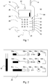
- Fig. 1 10 denotes an electronic battery-operated user terminal.
- a rechargeable battery 12 is provided for supplying energy to the user terminal 10.
- a disposable battery can also be used.
- the user terminal 10 is designed as a mobile radio terminal and contains, in addition to other components known to a person skilled in the art, in particular a mobile radio module 14 for sending and receiving data via a mobile radio network according to the GSM (Global System for Mobile Communication) or UMTS (Universal Mobile Telecommunications) System) standard.
- GSM Global System for Mobile Communication
- UMTS Universal Mobile Telecommunications
- the user terminal 10 is, for example, an MP3 player (playback device for audio data in the Moving Picturc Exports Group Audio Layer 3 Format), PDA (Personal Digital Assistant), laptop, digital camera, camcorder or navigation device.
- the electronic battery-operated user terminal 10 is characterized by the electronic generation, processing, exchange and reproduction of information or data for a user. It thus represents an interface between a user and electronic data or information available. Data or information can be, for example, texts, language, music, images, animations, films or multimedia data.
- the user terminal 10 makes several applications available to the user and contains the electrical components required for this. Possible applications include: Telephony, WAP (Wireless Application Protocol), SMS (Short Message Service), EMS (Enhanced Messaging Service) and MMS (Multimedia Messaging Service) applications, e-mail, Internet, WWW (World Wide Web), organizer, address book, taking pictures or videos, playing music, pictures or videos, games, satellite-based navigation and various interfaces for using applications with external devices, such as USB (Universal Serial Bus), Bluetooth or IrDa ( Infrared Data Association).
- WAP Wireless Application Protocol
- SMS Short Message Service
- EMS Enhanced Messaging Service
- MMS Multimedia Messaging Service
- the user terminal 10 enables images or videos to be recorded and for this purpose contains a digital camera 16 as an electrical component.
- external devices can be used via a Bluetooth interface 18 as an electrical component.
- the user terminal 10 enables the user to make telephony and for this purpose contains, in addition to a microphone 20, a loudspeaker 22 and the cellular radio module 14, all of the other electrical components required for this.
- An operating unit 24 and a display 26 are provided for the control and use of the user terminal 10 by a user.
- the display 26 can also be used to display application data such as images or videos.
- An energy supply of the electrical components of the user terminal 10 is controlled with an energy supply controller 28.
- the power supply controller 28 switches off the user terminal 10 when the battery 12 is at a predetermined minimum charge and terminates all applications or deactivates all electrical components of the user terminal 10.
- the energy supply controller 28 deactivates individual applications or the corresponding electrical components even before the minimum charge is reached when the battery 12 has further predetermined residual charges in order to increase the running time of important applications.
- the energy supply controller 28 uses predetermined priorities of the applications and residual charge values of the battery 12 assigned to them. When one of these residual charge values is reached, all applications with the corresponding priority are deactivated.
- the state of charge of the battery 12 is detected as the battery charge status by a detection device 30.
- the battery voltage can be checked continuously or periodically, for example.
- the battery charge status can be, for example, in percentages and then ranges from 100% for a fully charged battery 12 to 0% for a discharged battery 12.
- the energy supply control 28 determines whether individual applications or the entire user terminal 10 must be deactivated.
- the battery charge status is shown as a bar 32 on the display 26 for the user.
- a fully filled bar 32 corresponds to a fully charged battery 12 and a bar 32 without a filling corresponds to a discharged battery 12.
- the user terminal 10 also contains charging status means 34 for determining and displaying an application-specific battery charging status for each application.
- the application-specific battery charge status differs from the battery charge status by taking into account the deactivation of an application depending on the battery charge status. This fact will be described in more detail below.
- the Charge status means 34 determine the application-specific battery charge status of an application with the aid of the current battery charge status and the specified priority of the respective application.
- runtime determination means 36 a remaining runtime for each application is determined on the basis of the application-specific battery state of charge of an application and an energy consumption of active applications and is shown on the display 26 for the user. Furthermore, a battery load or an energy consumption of an application is shown by means 38 for displaying the battery load of an application for the user on the display 26 (see FIG. Fig. 2 ).
- actuating means 40 are provided in the user terminal 10. Furthermore, activation or deactivation of individual applications by the user with switching means 42 is possible.
- the actuating means 40 and the switching means 42 are actuated by the user with the aid of the operating unit 24 and the display 26.
- menus, symbols or soft keys can be used on the display 26, which the user selects with the aid of the operating unit 24.
- the detection device 30, the display 26, the charge status means 34, the runtime determination means 36, the means for displaying the battery load 38, as well as the priority setting means 40 and the switching means 42 together form a display device 44 for displaying a battery charge status and application-specific battery charge states.
- a display device 44 for displaying a battery charge status and application-specific battery charge states.
- the display 26 of the user terminal 10 it is also possible to use a further display. The same also applies to the detection device 30.
- the mode of operation of the display device 44 is described below together with a corresponding exemplary method for displaying a battery charge status and application-specific battery charge states. Both on Fig. 1 as well as on Fig. 2 Referenced. The same components are used in FIGS. 1 and 2 with corresponding references. As mentioned earlier, be three applications and their electrical components, namely the digital camera 16, the Bluetooth interface 16 and telephony are considered as an example. However, the display device 44 and the method can also be used for fewer or more applications.
- the user When using the user terminal 10, the user is permanently shown the battery charge status as a bar 32, see FIG. Fig. 1 .
- the user calls up the display device 44 by means of the operating unit 24.
- the bar 32 can be designed as a selectable symbol or softkey.
- the display device 44 then shows, among other things, application-specific battery charge states, remaining running times and battery utilization of individual applications on the display 26 for the user.
- a schematic and exemplary section of the display 26 is shown with this information.
- an application-specific battery charge state is shown for the digital camera 16 as a bar 50a together with a symbol or text 52a as an identifier. Since the digital camera 16 has a low priority and is deactivated by the energy supply control 28 before the Bluetooth interface 18 and telephony, the application-specific battery charge status 50a of the digital camera 16 differs from the battery charge status 32.
- a remaining running time 54a up to the deactivation and a battery utilization 56a are shown for the digital camera 16.
- the battery utilization 56a describes the energy requirement of the digital camera 16. All of these values can be displayed as text or symbols.
- a symbol 58a shows, as the status of the digital camera 16, whether the digital camera 16 is activated or deactivated. This symbol 58a simultaneously serves the user as a selectable symbol or softkey for operating the switching means 42 for activating or deactivating the digital camera 16.
- an application-specific battery charge state 50b, an identifier 52b, a remaining running time 54b, a battery load 56b and a status and switching symbol 58b and for telephony an application-specific battery charge state 50c, an identifier 52c, a remaining running time 54c, a battery load are used for the Bluetooth interface 18 56c and a status and switching symbol 58b are shown.
- the Bluetooth interface 18 has a medium priority, while the telephony has a high priority. The telephony is therefore deactivated together with the user terminal 10 by the energy supply control 28 when the battery is at least charged for operation.
- the application-specific battery charge status 50c of the telephony thus corresponds to the battery charge status 32.
- the application-specific battery charge status 50b of the Bluetooth differs -Interface 18 both from that of the digital camera 16 and from that of the telephony.
- the user receives extensive information in order to prepare for the upcoming deactivation of individual applications and to adjust his usage behavior accordingly. Furthermore, the setting means 40 for the priority and the switching means 42 provided in the display device 44 enable the user to exert extensive influence on the deactivation and activation of applications by the user terminal 10.
Description
Die Erfindung betrifft eine Anzeigevorrichtung zum Darstellen eines Batterieladestatus bei einem elektronischen batteriebetriebenen Benutzerendgerät nach Anspruch 1.The invention relates to a display device for displaying a battery charge status in an electronic battery-operated user terminal according to
Weiterhin betrifft die Erfindung ein elektronisches batteriebetriebenes Benutzerendgerät, welches für eine Mehrzahl von Anwendungen für einen Benutzer ausgebildet ist nach Anspruch 4.The invention further relates to an electronic battery-operated user terminal which is designed for a plurality of applications for a user according to
Ferner betrifft die Erfindung ein Verfahren zum Darstellen eines Batterieladestatus für ein elektronisches batteriebetriebenes Benutzerendgerät, welches für eine Mehrzahl von Anwendungen für einen Benutzer ausgebildet ist und dazu eine Mehrzahl von elektrischen Komponenten zur Durchführung der Anwendungen und eine Batterie zur Energieversorgung der elektrischen Komponenten enthält nach Anspruch 8.The invention also relates to a method for displaying a battery charge status for an electronic battery-operated user terminal, which is designed for a plurality of applications for a user and for this purpose contains a plurality of electrical components for carrying out the applications and a battery for supplying energy to the electrical components .
Als elektronisches Benutzerendgerät wird allgemein ein Endgerät zum elektronischen Erzeugen, Verarbeiten, Austauschen und Wiedergeben von Informationen oder Daten für einen Benutzer bezeichnet. Die Daten oder Informationen können beispielsweise Texte, Sprache, Musik, Bilder, Animationen, Filme oder Multimediadaten sein. Als mobile batteriebetriebene Benutzerendgeräte sind insbesondere Mobilfunktelefone für eine Kommunikation über ein Mobilfunknetz nach dem GSM- (Global System for Mobile Communication) oder UMTS- (Universal Mobile Telecommunications System) Standard, MP3-Player (Wiedergabegeräte für Audiodaten im Moving Picture Experts Group Audio Layer 3 Format), PDAs (Persönliche Digitale Assistenten), Laptops, digitale Kameras, Camcorder und Navigationsgeräte bekannt.An electronic user terminal is generally referred to as a terminal for electronically generating, processing, exchanging and reproducing information or data for a user. The data or information can be, for example, texts, language, music, images, animations, films or multimedia data. Mobile, battery-operated user terminals are in particular cellular phones for communication via a cellular network according to the GSM (Global System for Mobile Communication) or UMTS (Universal Mobile Telecommunications System) standard, MP3 players (playback devices for audio data in the Moving Picture Experts
Solche Benutzerendgeräte stellen einem Benutzer zunehmend mehrere Anwendungen zur Verfügung. So enthalten Mobilfunktelefone inzwischen üblicherweise eine digitale Kamera und einen MP3-Player. Weitere Beispiele sind MP3-Player und Navigationsgeräte, welche ein Anzeigen von digitalen Bildern oder Videos ermöglichen, PDAs mit Mobilfunktelefonie oder Mobilfunkendgeräte mit einem integrierten satellitengestützten Navigationssystem. Zudem verfügen viele Benutzerendgeräte über Schnittstellen, wie etwa nach dem Bluetooth- oder USB- (Universal Serial Bus) Standard, um Funktionen oder Anwendungen externer Geräte zu nutzen.Such user terminals increasingly make several applications available to a user. Cell phones now usually contain a digital camera and an MP3 player. Further examples are MP3 players and navigation devices that enable the display of digital images or videos, PDAs with cellular telephony or cellular radio terminals with an integrated satellite-supported navigation system. In addition, many user terminals have interfaces, such as those based on the Bluetooth or USB (Universal Serial Bus) standard, in order to use functions or applications of external devices.
Üblicherweise wird in batteriebetriebenen Benutzerendgeräten als Batterie eine Einwegbatterie oder ein wiederaufladbarer Akkumulator verwendet. Mittels einer Batteriestatusanzeige wird einem Benutzer der Batteriestatus angezeigt. Auf diese Weise wird es dem Benutzer ermöglicht, rechtzeitig eine Batterie auszutauschen oder einen Akkumulator wieder aufzuladen. Ferner kann der Benutzer eine Nutzung des Benutzerendgeräts auf den Batteriestatus abstimmen.Usually, a disposable battery or a rechargeable accumulator is used as the battery in battery-operated user terminals. The battery status is displayed to a user by means of a battery status display. This enables the user to replace a battery or recharge an accumulator in good time. Furthermore, the user can adapt a use of the user terminal to the battery status.
Um eine nachteilhafte vollständige Entladung, eine sogenannte Tiefentladung, eines Akkumulators zu vermeiden und aktive Anwendungen sicher und ohne Datenverlust zu beenden, erfolgt bei einem vorgegebenen Schwellwert typischerweise ein automatisches Ausschalten des Benutzerendgeräts. Bei batteriebetriebenen Benutzerendgeräten mit mehreren Anwendungen ist weiterhin ein frühzeitiges Deaktivieren von Anwendungen oder Funktionen mit geringer Priorität bekannt. Diese Anwendungen oder Funktionen werden bereits vor Erreichen des oben genannten Sehwellwerts deaktiviert, um so ein längere Restlaufzeit einer Batterie für wichtige Anwendungen zu erzielen. Für diese Vorgehensweise können beispielsweise weitere Sehwellwerte verwendet werden. So wird bei aktuellen Mobilfunktelefonen je nach Ladezustand der Batterie beispielsweise zunächst eine Kamera, später eine Bluetooth-Schnittstelle und schließlich die Telefonie und damit das Mobilfunktelefon als solches deaktiviert bzw. ausgeschaltet. Hierdurch wird eine längere Laufzeit für die bevorzugte Telefonie-Anwendung des Mobilfunkendgeräts erzielt.In order to avoid a disadvantageous complete discharge, a so-called total discharge, of a battery and to terminate active applications safely and without data loss, the user terminal is typically switched off automatically at a predetermined threshold value. In the case of battery-operated user terminals with several applications, applications must still be deactivated at an early stage or functions with low priority are known. These applications or functions are deactivated before the above-mentioned visual threshold value is reached in order to achieve a longer remaining battery life for important applications. For example, additional visual threshold values can be used for this procedure. In current cell phones, for example, depending on the battery charge level, first a camera, later a Bluetooth interface and finally telephony and thus the cell phone as such are deactivated or switched off. This results in a longer running time for the preferred telephony application of the mobile radio terminal.
In der
Die bekannten Benutzerendgeräte mit mehreren Anwendungen und einer vom Batteriestatus abhängigen Deaktivierung einzelner Anwendungen haben den Nachteil, dass für einen Benutzer nicht nachvollziehbar ist, ob und wann eine einzelne Anwendung oder Funktion deaktiviert wird. Diese Benutzerendgeräte verfügen zwar über eine Batteriestatusanzeige, welche dem Benutzer einen Ladezustand der Batterie darstellt und ihn auf eine unmittelbar bevorstehende Abschaltung des Benutzerendgeräts aufmerksam macht. Es ist aber für den Benutzer auch mittels der Batteriestatusanzeige nicht erkennbar, wann welche Anwendungen des Benutzerendgeräts deaktiviert werden, da eine Deaktivierung von einem Energiebedarf aktiver Anwendungen und dem Nutzungsverhalten des Benutzers abhängt.The known user terminals with several applications and a deactivation of individual applications depending on the battery status have the disadvantage that a user cannot understand whether and when an individual application or function is deactivated. These user terminals do have a battery status display which shows the user a charge status of the battery and draws his attention to an imminent shutdown of the user terminal. However, even by means of the battery status display, the user cannot recognize when which applications of the user terminal are deactivated, since deactivation depends on the energy requirement of active applications and the usage behavior of the user.
Die
Die
Die
Die
Aufgabe der Erfindung ist es daher, Nachteile des Standes der Technik zu vermeiden und einen Benutzer effektiv und benutzerfreundlich über eine Deaktivierung einzelner Anwendungen zu informieren.The object of the invention is therefore to avoid the disadvantages of the prior art and to inform a user effectively and in a user-friendly manner about the deactivation of individual applications.
Erfindungsgemäß wird die Aufgabe mit einer Anzeigevorrichtung, einem Benutzerendgerät und einem Verfahren gemäß der beigefügten Ansprüche gelöst.According to the invention, the object is achieved with a display device, a user terminal and a method according to the appended claims.
Die Erfindung beruht auf dem Prinzip, für verschiedene Anwendungen, welche bei unterschiedlichen, vorgegebenen Batterieladestatus und somit zu unterschiedlichen Zeitpunkten deaktiviert werden, jeweils einen anwendungsspezifischen Batterieladezustand anzuzeigen. Der anwendungsspezifische Batterieladezustand unterscheidet sich von dem Batterieladestatus durch Berücksichtigung der vom Batterieladestatus abhängigen Deaktivierung der Anwendung. Wird beispielsweise eine Anwendung durch die Energieversorgungssteuerung bei halbvoller Batterie deaktiviert, so zeigt der anwendungsspezifische Batterieladezustand dieser Anwendung bei halbvoller Batterie z.B. einen ungenügenden Ladezustand oder eine "leere" Batterie an.The invention is based on the principle of having an application-specific battery state of charge in each case for different applications, which are deactivated for different, predetermined battery charge statuses and thus at different times to display. The application-specific battery charge status differs from the battery charge status by taking into account the deactivation of the application depending on the battery charge status. If, for example, an application is deactivated by the power supply control when the battery is half full, the application-specific battery charge status of this application indicates, for example, an insufficient charge status or an "empty" battery when the battery is half full.
Bei der erfindungsgemäßen Anzeigevorrichtung und dem erfindungsgemäßen Benutzerendgeräts wird dem Benutzer für jede Anwendung ein anwendungsspezifischer Batterieladezustand angezeigt. Diese Information weist den Benutzer sehr effektiv auf eine bevorstehende Deaktivierung einer Anwendung hin. Dem Benutzer wird benutzerfreundlich ermöglicht, sein Nutzungsverhalten entsprechend der ermittelten und angezeigten anwendungsspezifischen Batterieladezustände anzupassen. Insbesondere wird der Benutzer nicht von einer Deaktivierung einer Anwendung überrascht, obwohl der Batterieladestatus des Benutzerendgeräts noch genügend Batterieladung für einen Betrieb des Benutzerendgeräts anzeigt.In the case of the display device according to the invention and the user terminal according to the invention, an application-specific battery charge status is displayed to the user for each application. This information is very effective in advising the user of an imminent deactivation of an application. The user is enabled in a user-friendly way to adapt his usage behavior according to the determined and displayed application-specific battery charge levels. In particular, the user is not surprised by a deactivation of an application, although the battery charge status of the user terminal still indicates sufficient battery charge for operation of the user terminal.
Entsprechende Vorteile ergeben sich bei dem erfindungsgemäßen Verfahren zum Darstellen eines Batterieladestatus für ein elektronisches batteriebetriebenes Benutzerendgerät. Wiederum wird der Benutzer rechtzeitig über eine Deaktivierung einer Anwendung informiert und kann sein Nutzugsverhalten entsprechend ausrichten.Corresponding advantages result from the method according to the invention for displaying a battery charge status for an electronic, battery-operated user terminal. Again, the user is informed in good time about the deactivation of an application and can adjust his usage behavior accordingly.
Bei der erfindungsgemäßen Anzeigevorrichtung sind Ladestatusmittel zum Ermitteln des anwendungsspezifischen Batterieladezustandes einer Anwendung mittels des Batterieladestatus und eine vorgegebene Priorität der Anwendung für eine Deaktivierung ausgebildet. Hierdurch eignet sich die erfindungsgemäße Anzeigevorrichtung besonders für Benutzerendgeräte, welche verschiedenen Anwendungen unterschiedliche Prioritäten zuweisen und einzelne Anwendungen jeweils in Abhängigkeit von einem Batterieladestatus und einer Priorität deaktivieren. Bei solchen Benutzerendgeräten wird das Ermitteln des anwendungsspezifischen Batterieladezustandes durch diese Ausbildung unkompliziert und schnell durchführbar.In the case of the display device according to the invention, charging status means are designed to determine the application-specific battery charging status of an application by means of the battery charging status and a predetermined priority of the application for deactivation. As a result, the display device according to the invention is particularly suitable for user terminals which assign different priorities to different applications and deactivate individual applications in each case as a function of a battery charge status and a priority. In the case of such user terminals, the determination of the application-specific battery state of charge is uncomplicated and can be carried out quickly as a result of this design.
Die erfindungsgemäße Anzeigevorrichtung umfasst Laufzeitbestimmungsmittel zum Bestimmen und Anzeigen einer Restlaufzeit einer Anwendung je nach anwendungsspezifischem Batterieladestatus und einem Energieverbrauch aktiver Anwendungen. Auf diese Weise wird ein Benutzer sehr benutzerfreundlich über Restlaufzeiten einzelner Anwendungen informiert und kann sein Nutzungsverhalten entsprechend anpassen. Der Benutzer erhält für verschiedene Anwendungen jederzeit Kenntnis über einen Zeitpunkt der Deaktivierung der Anwendung. Dadurch wird eine für den Benutzer überraschende Deaktivierung effektiv vermieden.The display device according to the invention comprises runtime determination means for determining and displaying a remaining runtime of an application depending on the application-specific battery charge status and an energy consumption of active applications. In this way, a user is informed in a very user-friendly manner about the remaining runtimes of individual applications and can adapt his usage behavior accordingly. For various applications, the user is always informed about the point in time when the application is deactivated. This effectively avoids a deactivation surprising for the user.
Durch Schaltmittel zum Aktivieren- oder Deaktivieren mindestens einer Anwendung durch den Benutzer wird eine vorteilhafte Weiterbildung der erfindungsgemäßen Anzeigevorrichtung erreicht. Mit dieser Maßnahme wird dem Benutzer eine umfangreiche Einflussnahme auf die Deaktivierung von Anwendungen ermöglicht. Je nach Bedarf ist eine Deaktivierung von nicht benötigten Anwendungen durchführbar. Dies führt zu einer längeren Restlaufzeit der verbleibenden aktiven Anwendungen. Ferner ist gegebenenfalls auch eine Aktivierung einer bereits deaktivierten Anwendung möglich, falls der Benutzer eine solche Anwendung dringend benutzen möchte.An advantageous development of the display device according to the invention is achieved by switching means for activating or deactivating at least one application by the user. This measure enables the user to exert extensive influence on the deactivation of applications. Applications that are not required can be deactivated as required. This leads to a longer remaining time for the remaining active applications. Furthermore, an activation of an application that has already been deactivated is also possible if the user urgently wishes to use such an application.
Die erfindungsgemäße Anzeigevorrichtung sieht Mittel zum Anzeigen einer Batterieauslastung durch eine Anwendung vor. Je nach Energiebedarf belasten verschiedene Anwendungen bzw. für diese Anwendung verwendete elektrische Komponenten des Benutzerendgeräts die Batterie unterschiedlich stark. Durch Anzeigen der Batterieauslastung oder des Energiebedarfs einer Anwendung erhält der Benutzer wichtige Informationen, nach denen er sein Nutzungsverhalten ausrichten kann. Beispielsweise wird hierdurch eine Entscheidung zum Nichtbenutzen oder Deaktivieren einer Anwendung wesentlich erleichtert.The display device according to the invention provides means for displaying battery utilization by an application. Depending on the energy requirement, different applications or electrical components of the user terminal used for this application load the battery to different degrees. By displaying the battery load or the energy requirement of an application, the user receives important information, according to which he can orient his usage behavior. For example, this makes a decision on not using or deactivating an application much easier.
Ferner umfasst die erfindungsgemäße Anzeigevorrichtung Stellmittel zum Vorgeben oder Ändern der Priorität einer Anwendung für eine Deaktivierung. Mit den Stellmitteln wird anwendungsfreundlich eine Anpassung der Priorität einer Anwendung für eine Deaktivierung in Abhängigkeit des Batterieladestatus ermöglicht. Je nach Bedürfnissen und Wünschen des Benutzers lässt sich eine Reihenfolge von automatischen Deaktivierungen verschiedener Anwendungen vorteilhaft durch den Benutzer einstellen.Furthermore, the display device according to the invention comprises adjusting means for specifying or changing the priority of an application for deactivation. With the adjusting means, an adaptation of the priority of an application for deactivation as a function of the is user-friendly Battery charge status enabled. Depending on the needs and desires of the user a sequence of automatic deactivations of various applications can advantageously be set by the user.
Bei einer bevorzugten Ausgestaltung des erfindungsgemäßen batteriebetriebenen Benutzerendgeräts sind die Ladestatusmittel zum Ermitteln des anwendungsspezifischen Batterieladezustandes einer Anwendung mittels des Batterieladestatus und einer vorgegebenen Priorität der Anwendung für eine Deaktivierung ausgebildet. Anhand einer vorgegebenen Priorität wird eine Anwendung durch eine Energieversorgungssteuerung bei einem vorgegebenen Batterieladestatus deaktiviert. Dabei ist eine gleichzeitige Deaktivierung von mehreren Anwendungen gleicher Priorität möglich. Durch Nutzung der Priorität einer Anwendung und des Batterieladestatus des Benutzerendgeräts wird ein effizientes Ermitteln von anwendungsspezifischen Batterieladezuständen durchführbar.In a preferred embodiment of the battery-operated user terminal according to the invention, the charging status means are designed to determine the application-specific battery charging status of an application by means of the battery charging status and a predetermined priority of the application for deactivation. On the basis of a predetermined priority, an application is deactivated by an energy supply controller when the battery charge status is predetermined. Simultaneous deactivation of several applications with the same priority is possible. By using the priority of an application and the battery charge status of the user terminal, it is possible to efficiently determine application-specific battery charge states.
Das Benutzerendgerät ist in einer vorteilhaften Ausbildung der Erfindung ein Mobilfunkendgerät für ein Mobilfunknetz. Moderne Mobilfunkendgeräte stellen einem Benutzer üblicherweise eine Vielzahl von Anwendungen, wie beispielsweise Telefonie, Textnachrichten, Spiele, Erzeugen und Anzeigen von Fotos und Videos und Wiedergabe von Musik, zur Verfügung. Die Erfindung lässt sich daher besonders vorteilhaft bei Mobilfunkendgeräten einsetzen. Ein als Mobilfunkendgerät ausgebildetes erfindungsgemäßes Benutzerendgerät informiert den Benutzer zu allen Zeiten über anwendungsspezifische Batterieladezustände der Anwendungen und somit auch über bevorstehende Deaktivierungen einzelner Anwendungen.In an advantageous embodiment of the invention, the user terminal is a mobile radio terminal for a mobile radio network. Modern mobile radio terminals usually provide a user with a large number of applications, such as telephony, text messages, games, creating and displaying photos and videos and playing music, for example. The invention can therefore be used particularly advantageously in mobile radio terminals. A user terminal according to the invention embodied as a mobile radio terminal informs the user at all times about application-specific battery charge states of the applications and thus also about upcoming deactivations of individual applications.
Eine bevorzugte Ausbildung des erfindungsgemäßen Verfahrens zum Darstellen eines Batterieladestatus für ein elektronisches batteriebetriebenes Benutzerendgerät verwendet zum Ermitteln des anwendungsspezifischen Batterieladezustandes einer Anwendung ebenfalls den Batterieladestatus und eine vorgegebene Priorität der Anwendung für eine Deaktivierung. Entsprechend der jeweiligen Ausgestaltung des erfindungsgemäßen Benutzerendgeräts und der erfindungsgemäßen Anzeigevorrichtung wird auf diese Weise ein schnelles und effizientes Ermitteln von anwendungsspezifischen Batterieladezuständen ermöglicht.A preferred embodiment of the method according to the invention for displaying a battery charge status for an electronic battery-operated user terminal also uses the battery charge status and a predetermined priority of the application for deactivation to determine the application-specific battery charge status of an application. In accordance with the respective configuration of the user terminal according to the invention and the display device according to the invention, a quick and efficient determination of application-specific battery states of charge is made possible in this way.
Weitere Ausbildungen des erfindungsgemäßen Benutzerendgeräts und des erfinderischen Verfahrens korrespondieren jeweils mit einer oben beschriebenen Ausgestaltung der Anzeigevorrichtung und verfügen daher über entsprechende Vorteile.Further developments of the user terminal according to the invention and the inventive method each correspond to an embodiment of the display device described above and therefore have corresponding advantages.
Ferner ergeben sich weitere Ausgestaltungen und Vorteile aus dem Gegenstand der Unteransprüche, sowie der Zeichnungen mit der dazugehörigen Beschreibung.Furthermore, further refinements and advantages result from the subject matter of the subclaims and the drawings with the associated description.
Ein Ausführungsbeispiel der Erfindung ist nachstehend unter Bezugnahme auf die zugehörigen Zeichnungen näher erläutert.An embodiment of the invention is explained in more detail below with reference to the accompanying drawings.
- Fig. 1Fig. 1
- zeigt in einer schematischen Prinzipskizze ein Ausführungsbeispiel einer erfindungsgemäßen Anzeigevorrichtung für ein Benutzerendgerät.shows in a schematic principle sketch an embodiment of a display device according to the invention for a user terminal.
- Fig. 2Fig. 2
-
zeigt einen schematischen Ausschnitt einer Anzeige des Ausführungsbeispiels nach
Fig. 1 .FIG. 11 shows a schematic section of a display of the exemplary embodiment according to FIGFig. 1 .
In
In anderen Ausführung ist das Benutzerendgerät 10 beispielsweise als MP3-Player (Wicdcrgabcgcrät für Audiodaten im Moving Picturc Exports Group Audio Layer 3 Format), PDA (Persönlicher Digitaler Assistent), Laptop, digitale Kamera, Camcorder oder Navigationsgerät ausgebildet. Allgemein zeichnet sich das elektronische batteriebetriebene Benutzerendgerät 10 durch elektronisches Erzeugen, Verarbeiten, Austauschen und Wiedergeben von Informationen oder Daten für einen Benutzer aus. Es stellt somit eine Schnittstelle zwischen einem Benutzer und elektronischen vorliegenden Daten oder Informationen dar. Daten oder Informationen können beispielsweise Texte, Sprache, Musik, Bilder, Animationen, Filme oder Multimediadaten sein.In another embodiment, the
Das Benutzerendgerät 10 stellt dem Benutzer mehrere Anwendungen zur Verfügung und enthält dazu notwenige elektrische Komponenten. Als Anwendungen sind beispielsweise möglich: Telefonie, WAP- (Wireless Application Protocol), SMS- (Short Message Service), EMS- (Enhanced Messaging Service) und MMS- (Multimedia Messaging Service) Anwendungen, E-Mail, Internet, WWW (World Wide Web), Organizer, Adressbuch, Aufnahme von Bildern oder Videos, Wiedergabe von Musik, Bildern oder Videos, Spiele, satellitengestützte Navigation und verschiedene Schnittstellen zur Nutzung von Anwendungen mit externen Geräten, wie z.B. USB (Universal Serial Bus), Bluetooth oder IrDa (Infrared Data Association).The
Der Einfachheit halber werden im Folgenden nur drei Anwendungen des Benutzerendgeräts 10 exemplarisch näher betrachtet. Erstens ermöglicht das Benutzerendgerät 10 eine Aufnahme von Bildern oder Videos und enthält dafür als elektrische Komponente eine digitale Kamera 16. Zweitens ist eine Anwendung von externen Geräten über eine Bluetooth-Schnittstelle 18 als elektrische Komponente durchführbar. Und drittens ermöglicht das Benutzerendgerät 10 dem Benutzer Telefonie und enthält dazu neben einem Mikrofon 20, einem Lautsprecher 22 und dem Mobilfunkmodul 14 alle weiteren dafür notwendigen elektrischen Komponenten.For the sake of simplicity, only three applications of the
Zur Steuerung und Nutzung des Benutzerendgeräts 10 durch einen Benutzer sind eine Bedienungseinheit 24 und eine Anzeige 26 vorgesehen. Mit der Anzeige 26 lassen sich neben Kontroll-, Status- und Steuerungsinformationen des Benutzerendgeräts 10 auch Anwendungsdaten, wie beispielsweise Bilder oder Videos darstellen.An operating
Mit einer Energieversorgungssteuerung 28 wird eine Energieversorgung der elektrischen Komponenten des Benutzerendgeräts 10 gesteuert. Einerseits schaltet die Energieversorgungssteuerung 28 das Benutzerendgerät 10 bei einer vorgegebenen Mindestladung der Batterie 12 ab und beendet dazu alle Anwendungen bzw. deaktiviert alle elektrischen Komponenten des Benutzerendgeräts 10. Auf diese Weise werden alle Anwendungen ordnungsgemäß beendet und eine schädliche vollständige Entladung der Batterie 12 vermieden. Andererseits werden durch die Energieversorgungssteuerung 28 einzelne Anwendungen bzw. die entsprechenden elektrischen Komponenten bereits vor Erreichen der Mindestladung bei weiteren vorgegebenen Restladungen der Batterie 12 deaktiviert, um eine Laufzeit wichtiger Anwendungen zu erhöhen. Dazu verwendet die Energieversorgungssteuerung 28 vorgegebene Prioritäten der Anwendungen und diesen zugeordnete Restladungswerte der Batterie 12. Beim Erreichen eines dieser Restladungswerte werden alle Anwendungen mit der entsprechenden Priorität deaktiviert.An energy supply of the electrical components of the
Der Ladungszustand der Batterie 12 wird als Batterieladestatus durch eine Erfassungsvorrichtung 30 erfasst. Dazu kann beispielsweise eine kontinuierliche oder periodische Überprüfung der Batteriespannung erfolgen. Der Batterieladestatus kann z.B. in Prozenten vorliegen und reicht dann von 100 % für eine vollständig geladene Batterie 12 bis 0% für eine entladene Batterie 12. Durch einen Vergleich des aktuellen Batterieladestatus mit vorgegebenen Batterieladestatus als vorgegebene Restladungswerte stellt die Energieversorgungssteuerung 28 fest, ob einzeln Anwendungen oder das gesamte Benutzerendgerät 10 deaktiviert werden müssen. Der Batterieladestatus wird in diesem Ausführungsbeispiel als Balken 32 auf der Anzeige 26 für den Benutzer dargestellt. Ein vollständig gefüllter Balken 32 entspricht einer vollständig geladenen Batterie 12 und ein Balken 32 ohne Füllung einer entladenen Batterie 12.The state of charge of the
Weiterhin enthält das Benutzerendgerät 10 Ladestatusmittel 34 zum Ermitteln und Anzeigen eines anwendungsspezifischen Batterieladezustands für jede Anwendung. Der anwendungsspezifische Batterieladezustand unterscheidet sich von dem Batterieladestatus durch Berücksichtigung der vom Batterieladestatus abhängigen Deaktivierung einer Anwendung. Dieser Umstand wird weiter unten näher bcschricbcn. Die Ladestatusmittel 34 ermitteln den anwendungsspezifischen Batterieladezustand einer Anwendung mit Hilfe des aktuellen Batterieladestatus und der vorgegebenen Priorität der jeweiligen Anwendung.The
Mit Laufzeitbestimmungsmittel 36 wird anhand des anwendungsspezifischen Batterieladezustands einer Anwendung und einem Energieverbrauch aktiver Anwendungen eine Restlaufzeit für jede Anwendung ermittelt und für den Benutzer auf der Anzeige 26 dargestellt. Ferner wird eine Batterieauslastung oder ein Energieverbrauch einer Anwendung durch Mittel 38 zum Anzeigen der Batterieauslastung einer Anwendung für den Benutzer auf der Anzeige 26 dargestellt (s.
Zum Vorgeben oder Ändern der Priorität einer Anwendung durch den Benutzer sind in dem Benutzerendgerät 10 Stellmittel 40 vorgesehen. Weiterhin ist ein Aktivieren oder Deaktivieren einzelner Anwendungen durch den Benutzer mit Schaltmitteln 42 möglich. Die Stellmittel 40 und die Schaltmittel 42 werden von dem Benutzer mit Hilfe der Bedienungseinheit 24 und der Anzeige 26 betätigt. Dazu können beispielsweise Menüs, Symbole oder Softkey auf der Anzeige 26 verwendet werden, welche der Benutzer mit Hilfe der Bedienungseinheit 24 auswählt.For the user to specify or change the priority of an application, actuating means 40 are provided in the
Die Erfassungsvorrichtung 30, die Anzeige 26, die Ladestatusmittel 34, die Laufzeitbestimmungsmittel 36, die Mittel zum Anzeigen der Batterieauslastung 38, sowie die Prioritätsstellmittel 40 und die Schaltmittel 42 bilden zusammen eine Anzeigevorrichtung 44 zum Darstellen eines Batterieladestatus und anwendungsspezifischer Batterieladezustände. Statt der Anzeige 26 des Benutzerendgeräts 10 ist auch eine Verwendung einer weiteren Anzeige möglich. Entsprechendes gilt auch für die Erfassungsvorrichtung 30.The
Im Folgenden wird die Funktionsweise der Anzeigevorrichtung 44 zusammen mit einem entsprechenden beispielhaften Verfahren zum Darstellen eines Batterieladestatus und anwendungsspezifischer Batterieladezustände beschrieben. Dabei wird sowohl auf
Bei einer Benutzung des Benutzerendgeräts 10 wird dem Benutzer permanent der Batterieladestatus als Balken 32 dargestellt, s.
In
Weiterhin wird für die digitale Kamera 16 eine Restlaufzeit 54a bis zur Deaktivierung und eine Batterieauslastung 56a dargestellt. Die Batterieauslastung 56a beschreibt den Energiebedarf der digitalen Kamera 16. Alle diese Werte können als Text oder symbolisch dargestellt werden. Ferner wird durch ein Symbol 58a als Status der digitalen Kamera 16 dargestellt, ob die digitale Kamera 16 aktiviert oder deaktiviert ist. Dieses Symbol 58a dient dem Benutzer gleichzeitig als anwählbares Symbol oder Softkey zur Bedienung der Schaltmittel 42 zum Aktivieren oder Deaktivieren der digitalen Kamera 16.Furthermore, a remaining
Entsprechend wird für die Bluetooth-Schnittstelle 18 ein anwendungsspezifischer Batterieladezustand 50b, ein Bezeichner 52b, eine Restlaufzeit 54b, eine Batterieauslastung 56b und ein Status- und Schaltsymbol 58b und für die Telefonie ein anwendungsspezifischer Batterieladezustand 50c, ein Bezeichner 52c, eine Restlaufzeit 54c, eine Batterieauslastung 56c und ein Status- und Schaltsymbol 58b dargestellt. Die Bluetooth-Schnittstelle 18 besitzt eine mittlere Priorität, während die Telefonie über eine hohe Priorität verfügt. Die Telefonie wird deshalb zusammen mit dem Benutzerendgerät 10 von der Energieversorgungssteuerung 28 bei der Mindestladung der Batterie für einen Betrieb deaktiviert. Der anwendungsspezifische Batterieladezustand 50c der Telefonie entspricht somit dem Batterieladestatus 32. Da die Bluetooth-Schnittstelle 18 bei einem Restladungswert der Batterie 12 zwischen dem der digitalen Kamera 16 und der Mindestladung der Batterie von der Energieversorgungssteuerung 28 deaktiviert wird, unterscheidet sich der anwendungsspezifische Batterieladezustand 50b der Bluetooth-Schnittstelle 18 sowohl von dem der digitalen Kamera 16 als auch von dem der Telefonie.Accordingly, an application-specific
Durch die Anzeigevorrichtung 44 und das entsprechenden Verfahren erhält der Benutzer umfangreiche Informationen, um sich auf bevorstehende Deaktivierungen einzelner Anwendungen vorzubereiten und sein Nutzungsverhalten entsprechend auszurichten. Weiterhin wird dem Benutzer durch die in der Anzeigevorrichtung 44 vorgesehenen Stellmittel 40 für die Priorität und die Schaltmittel 42 eine weitreichende Einflussnahme auf das Deaktivieren und Aktivieren von Anwendungen durch das Benutzerendgerät 10 ermöglicht.By means of the
Claims (10)
- A display device (44) for representing a battery charging status (32) in an electronic battery-operated user terminal (10), which is configured for a plurality of applications for a user, whereina) the user terminal (10) comprises- a plurality of electric components (16, 18) for carrying out the applications,- a battery (12) for the energy supply of the electric components (16, 18) and- an energy supply control (28) for deactivating the electric components (16, 18) of individual applications in case of a respectively predetermined battery charging statusandb) the display device (44) of the user terminal (10) comprises- a detection device (30) for detecting the battery charging status (32) of the user terminal,- a display (26) for representing the battery charging status (32) of the entire user terminal (10),- charging status means (34) for determining and displaying an application-specific battery charging status (50a, 50b, 50c) for at least one of the applications,- time determining means (36) for determining and displaying a remaining time (54a, 54b, 54c) of an application depending on the application-specific battery charging state (50a, 50b, 50c) and an energy consumption of active applications,
and- adjusting means (40) for defining or changing the priority of an application for a deactivation, characterized in that the display device (44) comprises means (38) for displaying a respective battery utilization (56a, 56b, 56c) by an application. - A display device (44) according to claim 1, characterized in that the charging status means (34) for determining and displaying the application-specific battery charging status (50a, 50b, 50c) of an application are configured for a deactivation on the base of the battery charging state (32) and a predetermined priority of the application.
- A display device (44) according to claim 1 or claim 2, characterized in that switching means (42) for activating or deactivating at least one application by the user are provided.
- An electronic battery-operated user terminal (10), which is configured for a plurality of applications for a user, wherein the user terminal (10) comprises- a plurality of electric components (16, 18) for carrying out the applications,- a battery (12) for the energy supply of the electric components (16, 18) and- an energy supply control (28) for deactivating the electric components (16, 18) of individual applications in case of a respectively predetermined battery charging status, as well as- a display device (44) comprising- a detection device (30) for detecting a battery charging status (32) of the user terminal,- an energy supply control (28) for deactivating the electric components (16, 18) of individual applications in case of a respectively predetermined battery charging status- a display (26) for representing the entire battery charging status (32) of the user terminal (10),- charging status means (34) for determining and displaying an application-specific battery charging status (50a, 50b, 50c) for at least one of the applications,- time determining means (36) for determining and displaying a remaining time (54a, 54b, 54c) of an application depending on the application-specific battery charging state (50a, 50b, 50c) and an energy consumption of active applications,
and- adjusting means (40) for defining or changing the priority of an application for a deactivation, characterized in that the display device (44) comprises means for displaying a respective battery utilization by an application. - An electronic battery-operated user terminal (10) according to claim 4, characterized in that the charging status means (34) for determining the application-specific battery charging state (50a, 50b, 50c) of an application are configured for a deactivation on the base of the battery status (32) and a predetermined priority of the application.
- An electronic battery-operated user terminal (10) according to claim 4 or claim 5, characterized in that switching means (42) are provided for the user for activating or deactivating at least one application.
- An electronic battery-operated user terminal (10) according to one of the claims 4 to 6, characterized in that the user terminal (10) is a mobile terminal for a mobile radio network.
- A method for representing a battery charging status (32) of an electronic battery-operated user terminal (10), which is configured for a plurality of applications for a user, and which therefore comprises a plurality of electric components (16, 18) for carrying out the applications and a battery (12) for supplying energy to the electric components (16, 18), comprising the process steps:- detecting the battery status (32) by means of a detection unit (30),- deactivating the electric components (16, 18) of individual applications in case of a respectively predefined battery charging status by means of an energy supply control (28),- representing the battery status (32) on a display (26),- determining and displaying of an application-specific battery charging state (50a, 50b, 50c) for at least one of the applications by means of charging status means (34),- determining and displaying a remaining time (54a, 54b, 54c) of an application depending on the application-specific battery charging state (50a, 50b, 50c) and an energy consumption of active applications by means of time-determining means (36),- and predefining or changing the priority of an application by means of adjusting means (40), characterized by displaying a respective battery utilization (56a, 56b, 56c), which is caused by an application.
- A method according to claim 8, characterized in that for determining the application-specific battery charging state (50a, 50b, 50c) of an application the battery charging status (32) and a predefined priority of the application are used for a deactivation.
- A method according to claim 8 or claim 9, characterized in that an activation or deactivation of at least one application by the user is provided.
Applications Claiming Priority (1)
| Application Number | Priority Date | Filing Date | Title |
|---|---|---|---|
| DE102009031828A DE102009031828A1 (en) | 2009-07-03 | 2009-07-03 | Battery charge status indicator for a user terminal |
Publications (3)
| Publication Number | Publication Date |
|---|---|
| EP2270528A2 EP2270528A2 (en) | 2011-01-05 |
| EP2270528A3 EP2270528A3 (en) | 2014-09-24 |
| EP2270528B1 true EP2270528B1 (en) | 2021-06-30 |
Family
ID=42983348
Family Applications (1)
| Application Number | Title | Priority Date | Filing Date |
|---|---|---|---|
| EP10161033.5A Active EP2270528B1 (en) | 2009-07-03 | 2010-04-26 | Battery status display in connection with display of remaining time |
Country Status (3)
| Country | Link |
|---|---|
| US (1) | US8482259B2 (en) |
| EP (1) | EP2270528B1 (en) |
| DE (1) | DE102009031828A1 (en) |
Families Citing this family (22)
| Publication number | Priority date | Publication date | Assignee | Title |
|---|---|---|---|---|
| EP2501183B1 (en) * | 2011-03-14 | 2015-05-06 | BlackBerry Limited | Electronic device and method for application and profile sensitive battery power management |
| US8904198B1 (en) * | 2011-04-13 | 2014-12-02 | Adriano L. Pinto | Electrical device recharging kiosk assembly |
| CN102325219A (en) * | 2011-09-05 | 2012-01-18 | 北京百纳威尔科技有限公司 | Method and device for processing electric quantity of mobile terminal |
| US10401305B2 (en) * | 2012-02-15 | 2019-09-03 | Kla-Tencor Corporation | Time-varying intensity map generation for reticles |
| KR101917688B1 (en) * | 2012-05-21 | 2018-11-13 | 엘지전자 주식회사 | Mobile terminal and control method thereof |
| TWI494745B (en) * | 2013-11-18 | 2015-08-01 | Polybatt Energy Technology Co Ltd | Mobile power charging information detection display method |
| CN104852410A (en) * | 2014-02-18 | 2015-08-19 | 中兴通讯股份有限公司 | Mobile terminal and charging indication method thereof |
| CN104900927B (en) * | 2014-03-07 | 2017-08-08 | 世和能源科技股份有限公司 | The method of portable power source charge information detecting display |
| FR3021798B1 (en) * | 2014-05-28 | 2018-01-05 | Valeo Comfort And Driving Assistance | MOBILE TELEPHONE FOR ACCESSING AND / OR STARTING A MOTOR VEHICLE |
| EP3457152B1 (en) * | 2014-05-30 | 2020-04-08 | Apple Inc. | Battery usage tracking user interface |
| CN114115460A (en) | 2014-08-06 | 2022-03-01 | 苹果公司 | Reduced size user interface for battery management |
| US10019218B2 (en) | 2014-08-14 | 2018-07-10 | Edan Instruments, Inc. | Multi-display power-up animation systems and methods |
| US9629606B2 (en) * | 2014-08-14 | 2017-04-25 | Edan Instruments, Inc. | Portability enhancing hardware for a portable ultrasound system |
| WO2016032022A1 (en) * | 2014-08-27 | 2016-03-03 | 삼성전자주식회사 | Method for reducing battery consumption in electronic device |
| US9841466B2 (en) | 2015-12-30 | 2017-12-12 | Thunder Power New Energy Vehicle Development Company Limited | Dynamic battery level indicator |
| US10154829B2 (en) | 2016-02-23 | 2018-12-18 | Edan Instruments, Inc. | Modular ultrasound system |
| WO2017188841A1 (en) * | 2016-04-28 | 2017-11-02 | Yota Devices Ipr Limited | Notification method |
| US10955886B2 (en) * | 2016-05-12 | 2021-03-23 | Dell Products L.P. | Systems and methods for graceful termination of applications in response to power event |
| US10671510B1 (en) | 2016-06-24 | 2020-06-02 | Intuit, Inc. | Techniques for evaluating collected build metrics during a software build process |
| US10951043B2 (en) | 2017-06-04 | 2021-03-16 | Apple Inc. | Multi-device charging user interface |
| CN107517494A (en) * | 2017-08-31 | 2017-12-26 | 努比亚技术有限公司 | A kind of display methods of terminal battery electricity quantity, terminal and computer-readable recording medium |
| US11646591B2 (en) | 2019-05-09 | 2023-05-09 | Apple Inc. | Indication for protective charging mode |
Citations (1)
| Publication number | Priority date | Publication date | Assignee | Title |
|---|---|---|---|---|
| US20090164152A1 (en) * | 2007-12-20 | 2009-06-25 | Nokia Corporation | Method, Apparatus and Computer Program Product for Providing Power Consumption Notification and Management |
Family Cites Families (10)
| Publication number | Priority date | Publication date | Assignee | Title |
|---|---|---|---|---|
| JP2996559B2 (en) * | 1992-01-29 | 2000-01-11 | 本田技研工業株式会社 | Electric vehicle charging status display system |
| DE60004373T2 (en) | 2000-10-30 | 2004-04-01 | Sony International (Europe) Gmbh | Process and software for switching off battery-powered electronic devices and mobile phone equipped with them |
| US6445162B1 (en) * | 2001-02-06 | 2002-09-03 | Quallion Llc | Detecting a remaining battery capacity and a battery remaining capacity circuit |
| US20030158609A1 (en) * | 2002-02-19 | 2003-08-21 | Koninklijke Philips Electronics N.V. | Power saving management for portable devices |
| JP3990990B2 (en) * | 2003-01-24 | 2007-10-17 | キヤノン株式会社 | Charging device, electronic device, battery remaining amount display control method in charging device, battery remaining amount detection method in electronic device |
| DE10344359A1 (en) | 2003-09-24 | 2005-05-12 | Siemens Ag | Method and device for communication with a system |
| DE10345437A1 (en) * | 2003-09-30 | 2005-05-19 | Siemens Ag | Method for operating a mobile radio terminal with an operating system |
| US20080200220A1 (en) * | 2007-02-16 | 2008-08-21 | Jackson Bruce K | Methods and devices for limiting battery power consumption in a wireless communication device |
| US8090415B2 (en) * | 2008-12-12 | 2012-01-03 | Sony Ericsson Mobile Communications Ab | Intelligent battery warning system |
| US8427114B2 (en) * | 2009-06-23 | 2013-04-23 | Evergreen Micro Devices Co., Ltd. | Apparatus for controlling LED indicator of charging status at the primary control side of an AC-DC power charger |
-
2009
- 2009-07-03 DE DE102009031828A patent/DE102009031828A1/en not_active Withdrawn
-
2010
- 2010-04-26 EP EP10161033.5A patent/EP2270528B1/en active Active
- 2010-07-02 US US12/803,743 patent/US8482259B2/en active Active
Patent Citations (1)
| Publication number | Priority date | Publication date | Assignee | Title |
|---|---|---|---|---|
| US20090164152A1 (en) * | 2007-12-20 | 2009-06-25 | Nokia Corporation | Method, Apparatus and Computer Program Product for Providing Power Consumption Notification and Management |
Also Published As
| Publication number | Publication date |
|---|---|
| US8482259B2 (en) | 2013-07-09 |
| EP2270528A3 (en) | 2014-09-24 |
| EP2270528A2 (en) | 2011-01-05 |
| US20110001457A1 (en) | 2011-01-06 |
| DE102009031828A1 (en) | 2011-01-05 |
Similar Documents
| Publication | Publication Date | Title |
|---|---|---|
| EP2270528B1 (en) | Battery status display in connection with display of remaining time | |
| DE10197232B4 (en) | Portable electronic device with special battery reserve | |
| CN101438477B (en) | Portable terminal and function operation control method | |
| DE102012204897A1 (en) | Prediction of battery power consumption | |
| DE102006001837A1 (en) | A system and method for regulating a precharge current in a battery system | |
| DE112008003519T5 (en) | Techniques for bidirectional power management | |
| EP2063616A1 (en) | Method for performing display in cell phone and cell phone thereof | |
| CN101826740A (en) | Method for reducing power consumption when terminal is charged and terminal | |
| EP1577738B1 (en) | Pocket PC with several operating states | |
| DE10345437A1 (en) | Method for operating a mobile radio terminal with an operating system | |
| CN116018707A (en) | Battery charging method, device and storage medium | |
| CN112349973A (en) | Battery module, charging method and device, electronic device and readable storage medium | |
| CN104348140A (en) | Low electric quantity prompting method and electronic equipment | |
| EP0866979B1 (en) | Method for displaying a "low battery" state in electrical equipment with electrical energy stores and electrical equipment with electrical energy stores with means for displaying a "low battery" state | |
| DE102004023627A1 (en) | Configuration of a storage device | |
| CN112217242A (en) | Charging control method and device | |
| CN106129503A (en) | A kind of method of quick charge and electronic equipment | |
| CN106034182A (en) | Method, device and terminal for controlling electric quantity loss | |
| CN114123417A (en) | Battery control method, device, electronic equipment and storage medium | |
| CN111376784B (en) | Control method and system for power swapping station | |
| DE602004009278T2 (en) | Automated switching of user messaging profiles in a mobile device | |
| CN105515076B (en) | The method and device of adjusting parameter | |
| DE102004003332B4 (en) | Telephone device and method | |
| CN108574978B (en) | Method and device for automatically switching modes of communication terminal | |
| DE102021210527B3 (en) | Method for transitioning an entity of a user equipment from a first operational state to a second operational state |
Legal Events
| Date | Code | Title | Description |
|---|---|---|---|
| PUAI | Public reference made under article 153(3) epc to a published international application that has entered the european phase |
Free format text: ORIGINAL CODE: 0009012 |
|
| AK | Designated contracting states |
Kind code of ref document: A2 Designated state(s): AT BE BG CH CY CZ DE DK EE ES FI FR GB GR HR HU IE IS IT LI LT LU LV MC MK MT NL NO PL PT RO SE SI SK SM TR |
|
| AX | Request for extension of the european patent |
Extension state: AL BA ME RS |
|
| RIN1 | Information on inventor provided before grant (corrected) |
Inventor name: FAMULLA, FRANK |
|
| PUAL | Search report despatched |
Free format text: ORIGINAL CODE: 0009013 |
|
| AK | Designated contracting states |
Kind code of ref document: A3 Designated state(s): AT BE BG CH CY CZ DE DK EE ES FI FR GB GR HR HU IE IS IT LI LT LU LV MC MK MT NL NO PL PT RO SE SI SK SM TR |
|
| AX | Request for extension of the european patent |
Extension state: AL BA ME RS |
|
| RIC1 | Information provided on ipc code assigned before grant |
Ipc: G01R 31/36 20060101AFI20140819BHEP |
|
| 17P | Request for examination filed |
Effective date: 20150324 |
|
| RBV | Designated contracting states (corrected) |
Designated state(s): AT BE BG CH CY CZ DE DK EE ES FI FR GB GR HR HU IE IS IT LI LT LU LV MC MK MT NL NO PL PT RO SE SI SK SM TR |
|
| STAA | Information on the status of an ep patent application or granted ep patent |
Free format text: STATUS: EXAMINATION IS IN PROGRESS |
|
| 17Q | First examination report despatched |
Effective date: 20180329 |
|
| STAA | Information on the status of an ep patent application or granted ep patent |
Free format text: STATUS: EXAMINATION IS IN PROGRESS |
|
| GRAP | Despatch of communication of intention to grant a patent |
Free format text: ORIGINAL CODE: EPIDOSNIGR1 |
|
| STAA | Information on the status of an ep patent application or granted ep patent |
Free format text: STATUS: GRANT OF PATENT IS INTENDED |
|
| INTG | Intention to grant announced |
Effective date: 20210309 |
|
| GRAS | Grant fee paid |
Free format text: ORIGINAL CODE: EPIDOSNIGR3 |
|
| GRAA | (expected) grant |
Free format text: ORIGINAL CODE: 0009210 |
|
| STAA | Information on the status of an ep patent application or granted ep patent |
Free format text: STATUS: THE PATENT HAS BEEN GRANTED |
|
| AK | Designated contracting states |
Kind code of ref document: B1 Designated state(s): AT BE BG CH CY CZ DE DK EE ES FI FR GB GR HR HU IE IS IT LI LT LU LV MC MK MT NL NO PL PT RO SE SI SK SM TR |
|
| REG | Reference to a national code |
Ref country code: GB Ref legal event code: FG4D Free format text: NOT ENGLISH Ref country code: CH Ref legal event code: EP |
|
| REG | Reference to a national code |
Ref country code: DE Ref legal event code: R096 Ref document number: 502010016933 Country of ref document: DE Ref country code: AT Ref legal event code: REF Ref document number: 1406818 Country of ref document: AT Kind code of ref document: T Effective date: 20210715 |
|
| REG | Reference to a national code |
Ref country code: IE Ref legal event code: FG4D Free format text: LANGUAGE OF EP DOCUMENT: GERMAN |
|
| REG | Reference to a national code |
Ref country code: LT Ref legal event code: MG9D |
|
| PG25 | Lapsed in a contracting state [announced via postgrant information from national office to epo] |
Ref country code: FI Free format text: LAPSE BECAUSE OF FAILURE TO SUBMIT A TRANSLATION OF THE DESCRIPTION OR TO PAY THE FEE WITHIN THE PRESCRIBED TIME-LIMIT Effective date: 20210630 Ref country code: BG Free format text: LAPSE BECAUSE OF FAILURE TO SUBMIT A TRANSLATION OF THE DESCRIPTION OR TO PAY THE FEE WITHIN THE PRESCRIBED TIME-LIMIT Effective date: 20210930 Ref country code: HR Free format text: LAPSE BECAUSE OF FAILURE TO SUBMIT A TRANSLATION OF THE DESCRIPTION OR TO PAY THE FEE WITHIN THE PRESCRIBED TIME-LIMIT Effective date: 20210630 |
|
| REG | Reference to a national code |
Ref country code: NL Ref legal event code: MP Effective date: 20210630 |
|
| PG25 | Lapsed in a contracting state [announced via postgrant information from national office to epo] |
Ref country code: LV Free format text: LAPSE BECAUSE OF FAILURE TO SUBMIT A TRANSLATION OF THE DESCRIPTION OR TO PAY THE FEE WITHIN THE PRESCRIBED TIME-LIMIT Effective date: 20210630 Ref country code: GR Free format text: LAPSE BECAUSE OF FAILURE TO SUBMIT A TRANSLATION OF THE DESCRIPTION OR TO PAY THE FEE WITHIN THE PRESCRIBED TIME-LIMIT Effective date: 20211001 Ref country code: SE Free format text: LAPSE BECAUSE OF FAILURE TO SUBMIT A TRANSLATION OF THE DESCRIPTION OR TO PAY THE FEE WITHIN THE PRESCRIBED TIME-LIMIT Effective date: 20210630 Ref country code: NO Free format text: LAPSE BECAUSE OF FAILURE TO SUBMIT A TRANSLATION OF THE DESCRIPTION OR TO PAY THE FEE WITHIN THE PRESCRIBED TIME-LIMIT Effective date: 20210930 |
|
| PG25 | Lapsed in a contracting state [announced via postgrant information from national office to epo] |
Ref country code: PT Free format text: LAPSE BECAUSE OF FAILURE TO SUBMIT A TRANSLATION OF THE DESCRIPTION OR TO PAY THE FEE WITHIN THE PRESCRIBED TIME-LIMIT Effective date: 20211102 Ref country code: NL Free format text: LAPSE BECAUSE OF FAILURE TO SUBMIT A TRANSLATION OF THE DESCRIPTION OR TO PAY THE FEE WITHIN THE PRESCRIBED TIME-LIMIT Effective date: 20210630 Ref country code: RO Free format text: LAPSE BECAUSE OF FAILURE TO SUBMIT A TRANSLATION OF THE DESCRIPTION OR TO PAY THE FEE WITHIN THE PRESCRIBED TIME-LIMIT Effective date: 20210630 Ref country code: ES Free format text: LAPSE BECAUSE OF FAILURE TO SUBMIT A TRANSLATION OF THE DESCRIPTION OR TO PAY THE FEE WITHIN THE PRESCRIBED TIME-LIMIT Effective date: 20210630 Ref country code: EE Free format text: LAPSE BECAUSE OF FAILURE TO SUBMIT A TRANSLATION OF THE DESCRIPTION OR TO PAY THE FEE WITHIN THE PRESCRIBED TIME-LIMIT Effective date: 20210630 Ref country code: CZ Free format text: LAPSE BECAUSE OF FAILURE TO SUBMIT A TRANSLATION OF THE DESCRIPTION OR TO PAY THE FEE WITHIN THE PRESCRIBED TIME-LIMIT Effective date: 20210630 Ref country code: SK Free format text: LAPSE BECAUSE OF FAILURE TO SUBMIT A TRANSLATION OF THE DESCRIPTION OR TO PAY THE FEE WITHIN THE PRESCRIBED TIME-LIMIT Effective date: 20210630 Ref country code: SM Free format text: LAPSE BECAUSE OF FAILURE TO SUBMIT A TRANSLATION OF THE DESCRIPTION OR TO PAY THE FEE WITHIN THE PRESCRIBED TIME-LIMIT Effective date: 20210630 |
|
| PG25 | Lapsed in a contracting state [announced via postgrant information from national office to epo] |
Ref country code: PL Free format text: LAPSE BECAUSE OF FAILURE TO SUBMIT A TRANSLATION OF THE DESCRIPTION OR TO PAY THE FEE WITHIN THE PRESCRIBED TIME-LIMIT Effective date: 20210630 |
|
| REG | Reference to a national code |
Ref country code: DE Ref legal event code: R097 Ref document number: 502010016933 Country of ref document: DE |
|
| PG25 | Lapsed in a contracting state [announced via postgrant information from national office to epo] |
Ref country code: DK Free format text: LAPSE BECAUSE OF FAILURE TO SUBMIT A TRANSLATION OF THE DESCRIPTION OR TO PAY THE FEE WITHIN THE PRESCRIBED TIME-LIMIT Effective date: 20210630 |
|
| PLBE | No opposition filed within time limit |
Free format text: ORIGINAL CODE: 0009261 |
|
| STAA | Information on the status of an ep patent application or granted ep patent |
Free format text: STATUS: NO OPPOSITION FILED WITHIN TIME LIMIT |
|
| 26N | No opposition filed |
Effective date: 20220331 |
|
| PG25 | Lapsed in a contracting state [announced via postgrant information from national office to epo] |
Ref country code: IT Free format text: LAPSE BECAUSE OF FAILURE TO SUBMIT A TRANSLATION OF THE DESCRIPTION OR TO PAY THE FEE WITHIN THE PRESCRIBED TIME-LIMIT Effective date: 20210630 |
|
| REG | Reference to a national code |
Ref country code: CH Ref legal event code: PL |
|
| REG | Reference to a national code |
Ref country code: BE Ref legal event code: MM Effective date: 20220430 |
|
| PG25 | Lapsed in a contracting state [announced via postgrant information from national office to epo] |
Ref country code: MC Free format text: LAPSE BECAUSE OF FAILURE TO SUBMIT A TRANSLATION OF THE DESCRIPTION OR TO PAY THE FEE WITHIN THE PRESCRIBED TIME-LIMIT Effective date: 20210630 Ref country code: LU Free format text: LAPSE BECAUSE OF NON-PAYMENT OF DUE FEES Effective date: 20220426 Ref country code: LI Free format text: LAPSE BECAUSE OF NON-PAYMENT OF DUE FEES Effective date: 20220430 Ref country code: CH Free format text: LAPSE BECAUSE OF NON-PAYMENT OF DUE FEES Effective date: 20220430 |
|
| PG25 | Lapsed in a contracting state [announced via postgrant information from national office to epo] |
Ref country code: BE Free format text: LAPSE BECAUSE OF NON-PAYMENT OF DUE FEES Effective date: 20220430 |
|
| PG25 | Lapsed in a contracting state [announced via postgrant information from national office to epo] |
Ref country code: LT Free format text: LAPSE BECAUSE OF FAILURE TO SUBMIT A TRANSLATION OF THE DESCRIPTION OR TO PAY THE FEE WITHIN THE PRESCRIBED TIME-LIMIT Effective date: 20210630 Ref country code: IE Free format text: LAPSE BECAUSE OF NON-PAYMENT OF DUE FEES Effective date: 20220426 |
|
| REG | Reference to a national code |
Ref country code: AT Ref legal event code: MM01 Ref document number: 1406818 Country of ref document: AT Kind code of ref document: T Effective date: 20220426 |
|
| PG25 | Lapsed in a contracting state [announced via postgrant information from national office to epo] |
Ref country code: AT Free format text: LAPSE BECAUSE OF NON-PAYMENT OF DUE FEES Effective date: 20220426 |
|
| PGFP | Annual fee paid to national office [announced via postgrant information from national office to epo] |
Ref country code: FR Payment date: 20230425 Year of fee payment: 14 Ref country code: DE Payment date: 20230420 Year of fee payment: 14 |
|
| PGFP | Annual fee paid to national office [announced via postgrant information from national office to epo] |
Ref country code: GB Payment date: 20230419 Year of fee payment: 14 |
|
| PG25 | Lapsed in a contracting state [announced via postgrant information from national office to epo] |
Ref country code: HU Free format text: LAPSE BECAUSE OF FAILURE TO SUBMIT A TRANSLATION OF THE DESCRIPTION OR TO PAY THE FEE WITHIN THE PRESCRIBED TIME-LIMIT; INVALID AB INITIO Effective date: 20100426 |