EP2270344A1 - Ball joint and method of manufacturing the same - Google Patents
Ball joint and method of manufacturing the same Download PDFInfo
- Publication number
- EP2270344A1 EP2270344A1 EP09732611A EP09732611A EP2270344A1 EP 2270344 A1 EP2270344 A1 EP 2270344A1 EP 09732611 A EP09732611 A EP 09732611A EP 09732611 A EP09732611 A EP 09732611A EP 2270344 A1 EP2270344 A1 EP 2270344A1
- Authority
- EP
- European Patent Office
- Prior art keywords
- support bar
- housing
- ball
- stud
- ball joint
- Prior art date
- Legal status (The legal status is an assumption and is not a legal conclusion. Google has not performed a legal analysis and makes no representation as to the accuracy of the status listed.)
- Granted
Links
Images




Classifications
-
- B—PERFORMING OPERATIONS; TRANSPORTING
- B60—VEHICLES IN GENERAL
- B60G—VEHICLE SUSPENSION ARRANGEMENTS
- B60G7/00—Pivoted suspension arms; Accessories thereof
- B60G7/005—Ball joints
-
- B—PERFORMING OPERATIONS; TRANSPORTING
- B60—VEHICLES IN GENERAL
- B60G—VEHICLE SUSPENSION ARRANGEMENTS
- B60G7/00—Pivoted suspension arms; Accessories thereof
- B60G7/001—Suspension arms, e.g. constructional features
-
- F—MECHANICAL ENGINEERING; LIGHTING; HEATING; WEAPONS; BLASTING
- F16—ENGINEERING ELEMENTS AND UNITS; GENERAL MEASURES FOR PRODUCING AND MAINTAINING EFFECTIVE FUNCTIONING OF MACHINES OR INSTALLATIONS; THERMAL INSULATION IN GENERAL
- F16C—SHAFTS; FLEXIBLE SHAFTS; ELEMENTS OR CRANKSHAFT MECHANISMS; ROTARY BODIES OTHER THAN GEARING ELEMENTS; BEARINGS
- F16C11/00—Pivots; Pivotal connections
- F16C11/04—Pivotal connections
- F16C11/06—Ball-joints; Other joints having more than one degree of angular freedom, i.e. universal joints
- F16C11/0619—Ball-joints; Other joints having more than one degree of angular freedom, i.e. universal joints the female part comprising a blind socket receiving the male part
- F16C11/0623—Construction or details of the socket member
- F16C11/0657—Construction or details of the socket member the socket member being mainly made of plastics
-
- F—MECHANICAL ENGINEERING; LIGHTING; HEATING; WEAPONS; BLASTING
- F16—ENGINEERING ELEMENTS AND UNITS; GENERAL MEASURES FOR PRODUCING AND MAINTAINING EFFECTIVE FUNCTIONING OF MACHINES OR INSTALLATIONS; THERMAL INSULATION IN GENERAL
- F16C—SHAFTS; FLEXIBLE SHAFTS; ELEMENTS OR CRANKSHAFT MECHANISMS; ROTARY BODIES OTHER THAN GEARING ELEMENTS; BEARINGS
- F16C11/00—Pivots; Pivotal connections
- F16C11/04—Pivotal connections
- F16C11/06—Ball-joints; Other joints having more than one degree of angular freedom, i.e. universal joints
- F16C11/0685—Manufacture of ball-joints and parts thereof, e.g. assembly of ball-joints
-
- F—MECHANICAL ENGINEERING; LIGHTING; HEATING; WEAPONS; BLASTING
- F16—ENGINEERING ELEMENTS AND UNITS; GENERAL MEASURES FOR PRODUCING AND MAINTAINING EFFECTIVE FUNCTIONING OF MACHINES OR INSTALLATIONS; THERMAL INSULATION IN GENERAL
- F16C—SHAFTS; FLEXIBLE SHAFTS; ELEMENTS OR CRANKSHAFT MECHANISMS; ROTARY BODIES OTHER THAN GEARING ELEMENTS; BEARINGS
- F16C7/00—Connecting-rods or like links pivoted at both ends; Construction of connecting-rod heads
- F16C7/02—Constructions of connecting-rods with constant length
-
- B—PERFORMING OPERATIONS; TRANSPORTING
- B60—VEHICLES IN GENERAL
- B60G—VEHICLE SUSPENSION ARRANGEMENTS
- B60G2204/00—Indexing codes related to suspensions per se or to auxiliary parts
- B60G2204/40—Auxiliary suspension parts; Adjustment of suspensions
- B60G2204/416—Ball or spherical joints
-
- B—PERFORMING OPERATIONS; TRANSPORTING
- B60—VEHICLES IN GENERAL
- B60G—VEHICLE SUSPENSION ARRANGEMENTS
- B60G2206/00—Indexing codes related to the manufacturing of suspensions: constructional features, the materials used, procedures or tools
- B60G2206/01—Constructional features of suspension elements, e.g. arms, dampers, springs
- B60G2206/011—Modular constructions
-
- B—PERFORMING OPERATIONS; TRANSPORTING
- B60—VEHICLES IN GENERAL
- B60G—VEHICLE SUSPENSION ARRANGEMENTS
- B60G2206/00—Indexing codes related to the manufacturing of suspensions: constructional features, the materials used, procedures or tools
- B60G2206/01—Constructional features of suspension elements, e.g. arms, dampers, springs
- B60G2206/014—Constructional features of suspension elements, e.g. arms, dampers, springs with reinforcing nerves or branches
-
- B—PERFORMING OPERATIONS; TRANSPORTING
- B60—VEHICLES IN GENERAL
- B60G—VEHICLE SUSPENSION ARRANGEMENTS
- B60G2206/00—Indexing codes related to the manufacturing of suspensions: constructional features, the materials used, procedures or tools
- B60G2206/01—Constructional features of suspension elements, e.g. arms, dampers, springs
- B60G2206/016—Constructional features of suspension elements, e.g. arms, dampers, springs allowing controlled deformation during collision
-
- B—PERFORMING OPERATIONS; TRANSPORTING
- B60—VEHICLES IN GENERAL
- B60G—VEHICLE SUSPENSION ARRANGEMENTS
- B60G2206/00—Indexing codes related to the manufacturing of suspensions: constructional features, the materials used, procedures or tools
- B60G2206/01—Constructional features of suspension elements, e.g. arms, dampers, springs
- B60G2206/017—Constructional features of suspension elements, e.g. arms, dampers, springs forming an eye for the bushing
-
- B—PERFORMING OPERATIONS; TRANSPORTING
- B60—VEHICLES IN GENERAL
- B60G—VEHICLE SUSPENSION ARRANGEMENTS
- B60G2206/00—Indexing codes related to the manufacturing of suspensions: constructional features, the materials used, procedures or tools
- B60G2206/01—Constructional features of suspension elements, e.g. arms, dampers, springs
- B60G2206/10—Constructional features of arms
- B60G2206/11—Constructional features of arms the arm being a radius or track or torque or steering rod or stabiliser end link
-
- B—PERFORMING OPERATIONS; TRANSPORTING
- B60—VEHICLES IN GENERAL
- B60G—VEHICLE SUSPENSION ARRANGEMENTS
- B60G2206/00—Indexing codes related to the manufacturing of suspensions: constructional features, the materials used, procedures or tools
- B60G2206/01—Constructional features of suspension elements, e.g. arms, dampers, springs
- B60G2206/70—Materials used in suspensions
- B60G2206/71—Light weight materials
- B60G2206/7104—Thermoplastics
-
- B—PERFORMING OPERATIONS; TRANSPORTING
- B60—VEHICLES IN GENERAL
- B60G—VEHICLE SUSPENSION ARRANGEMENTS
- B60G2206/00—Indexing codes related to the manufacturing of suspensions: constructional features, the materials used, procedures or tools
- B60G2206/01—Constructional features of suspension elements, e.g. arms, dampers, springs
- B60G2206/80—Manufacturing procedures
- B60G2206/81—Shaping
- B60G2206/8101—Shaping by casting
- B60G2206/81012—Shaping by casting by injection moulding
-
- B—PERFORMING OPERATIONS; TRANSPORTING
- B60—VEHICLES IN GENERAL
- B60G—VEHICLE SUSPENSION ARRANGEMENTS
- B60G2206/00—Indexing codes related to the manufacturing of suspensions: constructional features, the materials used, procedures or tools
- B60G2206/01—Constructional features of suspension elements, e.g. arms, dampers, springs
- B60G2206/80—Manufacturing procedures
- B60G2206/82—Joining
- B60G2206/8209—Joining by deformation
- B60G2206/82092—Joining by deformation by press-fitting
-
- B—PERFORMING OPERATIONS; TRANSPORTING
- B60—VEHICLES IN GENERAL
- B60G—VEHICLE SUSPENSION ARRANGEMENTS
- B60G2206/00—Indexing codes related to the manufacturing of suspensions: constructional features, the materials used, procedures or tools
- B60G2206/01—Constructional features of suspension elements, e.g. arms, dampers, springs
- B60G2206/80—Manufacturing procedures
- B60G2206/82—Joining
- B60G2206/821—Joining by gluing
-
- B—PERFORMING OPERATIONS; TRANSPORTING
- B60—VEHICLES IN GENERAL
- B60G—VEHICLE SUSPENSION ARRANGEMENTS
- B60G2206/00—Indexing codes related to the manufacturing of suspensions: constructional features, the materials used, procedures or tools
- B60G2206/01—Constructional features of suspension elements, e.g. arms, dampers, springs
- B60G2206/90—Maintenance
- B60G2206/91—Assembly procedures
-
- F—MECHANICAL ENGINEERING; LIGHTING; HEATING; WEAPONS; BLASTING
- F16—ENGINEERING ELEMENTS AND UNITS; GENERAL MEASURES FOR PRODUCING AND MAINTAINING EFFECTIVE FUNCTIONING OF MACHINES OR INSTALLATIONS; THERMAL INSULATION IN GENERAL
- F16C—SHAFTS; FLEXIBLE SHAFTS; ELEMENTS OR CRANKSHAFT MECHANISMS; ROTARY BODIES OTHER THAN GEARING ELEMENTS; BEARINGS
- F16C2208/00—Plastics; Synthetic resins, e.g. rubbers
- F16C2208/20—Thermoplastic resins
- F16C2208/36—Polyarylene ether ketones [PAEK], e.g. PEK, PEEK
-
- F—MECHANICAL ENGINEERING; LIGHTING; HEATING; WEAPONS; BLASTING
- F16—ENGINEERING ELEMENTS AND UNITS; GENERAL MEASURES FOR PRODUCING AND MAINTAINING EFFECTIVE FUNCTIONING OF MACHINES OR INSTALLATIONS; THERMAL INSULATION IN GENERAL
- F16C—SHAFTS; FLEXIBLE SHAFTS; ELEMENTS OR CRANKSHAFT MECHANISMS; ROTARY BODIES OTHER THAN GEARING ELEMENTS; BEARINGS
- F16C2208/00—Plastics; Synthetic resins, e.g. rubbers
- F16C2208/20—Thermoplastic resins
- F16C2208/52—Polyphenylene sulphide [PPS]
-
- F—MECHANICAL ENGINEERING; LIGHTING; HEATING; WEAPONS; BLASTING
- F16—ENGINEERING ELEMENTS AND UNITS; GENERAL MEASURES FOR PRODUCING AND MAINTAINING EFFECTIVE FUNCTIONING OF MACHINES OR INSTALLATIONS; THERMAL INSULATION IN GENERAL
- F16C—SHAFTS; FLEXIBLE SHAFTS; ELEMENTS OR CRANKSHAFT MECHANISMS; ROTARY BODIES OTHER THAN GEARING ELEMENTS; BEARINGS
- F16C2208/00—Plastics; Synthetic resins, e.g. rubbers
- F16C2208/20—Thermoplastic resins
- F16C2208/66—Acetals, e.g. polyoxymethylene [POM]
-
- F—MECHANICAL ENGINEERING; LIGHTING; HEATING; WEAPONS; BLASTING
- F16—ENGINEERING ELEMENTS AND UNITS; GENERAL MEASURES FOR PRODUCING AND MAINTAINING EFFECTIVE FUNCTIONING OF MACHINES OR INSTALLATIONS; THERMAL INSULATION IN GENERAL
- F16C—SHAFTS; FLEXIBLE SHAFTS; ELEMENTS OR CRANKSHAFT MECHANISMS; ROTARY BODIES OTHER THAN GEARING ELEMENTS; BEARINGS
- F16C2326/00—Articles relating to transporting
- F16C2326/01—Parts of vehicles in general
- F16C2326/05—Vehicle suspensions, e.g. bearings, pivots or connecting rods used therein
-
- Y—GENERAL TAGGING OF NEW TECHNOLOGICAL DEVELOPMENTS; GENERAL TAGGING OF CROSS-SECTIONAL TECHNOLOGIES SPANNING OVER SEVERAL SECTIONS OF THE IPC; TECHNICAL SUBJECTS COVERED BY FORMER USPC CROSS-REFERENCE ART COLLECTIONS [XRACs] AND DIGESTS
- Y10—TECHNICAL SUBJECTS COVERED BY FORMER USPC
- Y10T—TECHNICAL SUBJECTS COVERED BY FORMER US CLASSIFICATION
- Y10T403/00—Joints and connections
- Y10T403/32—Articulated members
- Y10T403/32606—Pivoted
- Y10T403/32631—Universal ball and socket
-
- Y—GENERAL TAGGING OF NEW TECHNOLOGICAL DEVELOPMENTS; GENERAL TAGGING OF CROSS-SECTIONAL TECHNOLOGIES SPANNING OVER SEVERAL SECTIONS OF THE IPC; TECHNICAL SUBJECTS COVERED BY FORMER USPC CROSS-REFERENCE ART COLLECTIONS [XRACs] AND DIGESTS
- Y10—TECHNICAL SUBJECTS COVERED BY FORMER USPC
- Y10T—TECHNICAL SUBJECTS COVERED BY FORMER US CLASSIFICATION
- Y10T403/00—Joints and connections
- Y10T403/32—Articulated members
- Y10T403/32606—Pivoted
- Y10T403/32631—Universal ball and socket
- Y10T403/32729—Externally packed
Definitions
- the ball portion of the ball stud and the ball seat are used as the core in the die casting, when the stud portion is connected to the ball portion, die casting cannot be performed for the formation of the housing and the support bar. Due to this, after the die casting for the formation of the housing and the support bar, the stud portion was connected to the ball portion by resistance welding or the like, and the ball stud was thereby formed. Thus, strength of a connecting portion of the ball portion and the stud portion may be low, and reliability of the ball joint may be insufficient.
- the pivot member 200 is equipped with a ball seat 210, the housing 220, and the support bar 230.
- the housing 520 and the support bar 530 are mechanically engaged with each other, easy separation of the support bar 530 from the housing 520 can be prevented. Since the housing 520 and the support bar 530 are made of the same material, generation of backlash, crack, or the like, in which contact surfaces of the housing 520 and the support bar 530 may be separated from each other due to difference in thermal expansion coefficient, can be prevented. Thus, the reliability of the ball joint 10 can be improved.
Landscapes
- Engineering & Computer Science (AREA)
- General Engineering & Computer Science (AREA)
- Mechanical Engineering (AREA)
- Pivots And Pivotal Connections (AREA)
- Vehicle Body Suspensions (AREA)
- Finger-Pressure Massage (AREA)
Abstract
Description
- The present invention relates to a ball joint provided to stabilizers of vehicles (automobiles and the like), and to a production method therefor.
- For example, in a suspension mechanism of a vehicle, in order to rotatably and vibratably connect two portions (for example, a stabilizer and a shock absorber, or a stabilizer and a suspension arm) which can move relatively, a ball joint may be used.
- This ball joint is equipped with a ball stud, a ball seat, a housing, a support bar, and a dust cover. The ball stud has a stud portion and a ball portion. The ball seat has a bearing function and the ball portion is press-fitted therein. The housing holds the ball seat therein. The support bar supports the housing. The dust cover prevents infiltration of foreign matter which may inhibit sliding and vibration of the ball portion of the ball stud in the ball seat.
- In a production method for this ball joint, a housing and a support bar were separately formed, and the support bar, which was made of steel (for example, S200C), was connected to the housing, which was produced by press forming or the like, by resistance welding or carbon dioxide welding.
- When the support bar and the like are made of a steel material, the support bar is the heaviest of the components (the ball stud, the dust cover, the support bar, and the ball seat) of one ball joint. For example, the weight of the support bar having an axial direction length of 325 mm is 260 grams, the total weight of the components other than the support bar is 130 grams, and the weight of support bar is two times as heavy as those of the components other than the support bar. That is, the weight (130 grams) of the support bar is two thirds of the weight (390 grams) of the ball joint. Due to this, the weight of the ball joint is heavier, and it is therefore difficult for the ball joint to contribute to the weight reduction of the vehicle.
- When the housing and the support bar are separately formed, the support bar is connected to the housing by resistance welding or the like. Thus, when endurance tests were performed in which a tensile load or a compressive load was applied on the support bar in an axial direction thereof, it was confirmed that breakage occurs at a welded portion before a predetermined number of times of conducting the endurance test. Due to this, in a housing and a support bar which are integrally formed, a strength of a connecting portion may be low, and reliability of a ball joint may be insufficient.
- For example, Japanese Unexamined Patent Application Publication No.
2004-316771 - However, in the technique proposed above, in the die casting, a melted aluminum alloy is supplied to the die using the ball portion of the ball stud and the ball seat as the core, so that an outer surface of the ball seat made of a resin is deteriorated. Due to this, a contact portion of the ball seat which contacts the ball portion is maintained in good condition, but resin thickness thereof has a subtle unevenness. Thus, sliding and vibration of the ball stud may be unstable. That is, when a tensile load or a compressive load is applied on the support bar in an axial direction of the ball stud and in a radial direction of the ball portion, deflection amount of the ball seat may be uneven. Due to this, sliding and vibration of the ball stud may be irregular. As a result, the performance of the ball joint cannot be sufficient, and the ball joint may not be sufficiently reliable.
- Since the ball portion of the ball stud and the ball seat are used as the core in the die casting, when the stud portion is connected to the ball portion, die casting cannot be performed for the formation of the housing and the support bar. Due to this, after the die casting for the formation of the housing and the support bar, the stud portion was connected to the ball portion by resistance welding or the like, and the ball stud was thereby formed. Thus, strength of a connecting portion of the ball portion and the stud portion may be low, and reliability of the ball joint may be insufficient.
- An object of the present invention is to provide a ball joint which can have high reliability and reduced weight.
- According to first aspect of the present invention, a ball joint includes: a ball stud having a columnar stud portion and a ball portion which has a spherical side surface and a center positioned on an axis of the stud portion; a ball seat which is made of a resin and has a spherical recess portion into which the ball portion is relatively rotatably and slidably fitted; a housing which is made of a resin and holds the ball seat therein; and a support bar which is integrally formed with the housing, wherein the support bar has a bar portion which is a center portion extending along an axis of the support bar.
- According to second aspect of the present invention, a ball joint includes: a ball stud having a columnar stud portion and a ball portion which has a spherical side surface and a center positioned on an axis of the stud portion; a ball seat which is made of a resin and has a spherical recess portion into which the ball portion is relatively rotatably and slidably fitted; a housing which is made of a resin and holds the ball seat therein; and a support bar which is connected with the housing, wherein the housing has a boss portion having an opening portion which opens at a side surface of the housing, the support bar has a bar portion and a flange portion, the bar portion being a center portion extending along an axis of the support bar, the flange portion formed at a leading end portion of the bar portion so as to have a flanged shape, and the support bar is connected with the boss portion so that the opening portion is formed in close contact with and covers an entire periphery of the flange portion.
- In the aspect of the present invention, since the housing and the support bar are integrally formed, when a tensile load, a compressive load, or the like is applied in the axial direction of the support bar, a boundary portion between the housing and the support bar can have the load applied thereto. Since the support bar is connected with the boss portion so that the opening portion is formed in close contact with and covers an entire periphery of the flange portion, when a tensile load, a compressive load, or the like is applied in the axial direction of the support bar, a boundary portion between the housing and the support bar can have the load applied thereto. Thus, when the load is applied in the axial direction of the support bar, breakage from the boundary portion between the housing and the support bar can be prevented. That is, the ability to support the load in the axial direction of the support bar can be improved, and the strength of the ball joint can be improved. As a result, the reliability of the ball joint can be improved. The weight of the ball joint can be reduced. It is unnecessary to consider electrical corrosion occurring when an aluminum alloy is used.
- According to a preferred embodiment of the present invention, the resin may be polyphenylene sulfide, polyether ether ketone, or the like. For example, in the material (polyphenylene sulfide, polyether ether ketone, or the like), when injection conditions for formation of the housing and support bar are selected, generation of burr can be prevented. The material (polyphenylene sulfide, polyether ether ketone, or the like) can have a heat resistance and strength so as to resist the heat in caulking of thermal caulking portion of the ball seat.
- According to a preferred embodiment of the present invention, the support bar may extend in an axial direction of the support bar and may have plural protruding ridges which are integrally formed with the bar portion in a circumferential direction of the support bar. In this embodiment, when a load is applied in the axial direction of the support bar, buckling of the support bar can be prevented. That is, stiffness of the support bar can be improved. The resin used can be reduced, so that the weight and the cost can be reduced.
- According to a preferred embodiment of the present invention, the support bar may have plural protruding portions at the flange portion of the bar portion, and the opening portion may be formed in close contact with and may cover entire peripheries of the protruding portions. In this embodiment, when a torsional load is applied on the housing or the support bar, rotation of the housing or the support bar with respect to each other can be prevented. Thus, when a torsional load is applied on the housing or the support bar, change of the phase angle between the housings can be prevented, and the function of the ball joint can be maintained. The protruding portion of this embodiment can be a line protruding portion, a convex protruding portion, or the like.
- According to a preferred embodiment of the present invention, the support bar may have a straight portion formed at a side of the housing and within a predetermined range in an axial direction of the support bar, the axial direction being apart from the boss portion. In this embodiment, when the housing is formed at the leading end portion of the support bar after formation of the support bar, the support bar can be supported by supporting the straight portion, and the housing can be formed. Thus, when the housing is formed, the support bar can be easily supported, so that change of the support position of the support bar can be prevented, and leakage of the resin from the die for forming the housing can be prevented. The straight portion of this embodiment may have a shape so as to easily support the support bar. The straight portion of this embodiment can have a columnar shape, a rectangular columnar shape, or the like.
- According to a preferred embodiment of the present invention, the housing may be formed to have an upper end side and a bottom side, the upper end side having an outer diameter larger than that of the bottom side. In this embodiment, the strength of the upper side of the housing having the recess portion which may be weak can be greater. Thus, when a tensile load is applied on the housing toward an axial direction of the support bar, the housing can have the load applied thereto, and breakage of the housing can be prevented. That is, the strength of the housing can be greater. The resin used can be reduced, so that weight and cost can be reduced.
- According to a preferred embodiment of the present invention, the ball joint may include: a dust cover which has an end contacting the stud portion and the other end contacting an upper end of the housing; an upper end portion which is formed at the upper end of the housing so as to have a flat contact portion which the dust cover contacts when the ball stud vibrates; and a flat portion which is formed at a side of the support bar so as to be flush with the upper end portion. In this embodiment, the entire portion, which the dust cover contacts in vibration of the ball stud, can be flat. Thus, in vibration of the ball stud, contact of the dust cover to a protruding portion (a corner portion or the like) can be prevented, and breakage of the dust cover can be prevented.
- According to another aspect of the present invention, a production method for a ball joint includes: injection molding in which a support bar having a flange portion having a flanged shape and a straight portion is formed by injection using a resin; and insert molding in which the straight portion is supported and a housing having a boss portion is formed by injection using a resin so that the boss portion covers a leading end portion of the support bar which includes the flange portion.
- In the aspect of the present invention, when the housing is formed at the leading end portion of the support bar, the straight portion is supported, and the housing is formed. Thus, the support bar can be easily supported, so that change of the relative position of the support bar to the die for forming the housing can be prevented. Therefore, leakage of the resin from the die for forming the housing can be prevented. The end portion of the support bar can be strongly compressed and secured by molding shrinkage of the housing formed after the formation of the support bar. Thus, generation of backlash, in which contact surfaces of the housing and the support bar may be separated from each other, can be prevented, so that the reliability of the ball joint can be improved.
- According to the present invention, a ball joint, which has high reliability and reduced weight, can be produced.
-
-
Fig. 1 is a diagram which shows a ball joint. -
Fig. 2 is a diagram showing a condition in which a ball joint is vibrated. -
Fig. 3 is a perspective view showing a portion of a pivot member. -
Fig. 4 is a cross sectional view which is taken along line X-X inFig. 3 and which shows a support bar. -
Fig. 5 is a perspective view which shows a first modification example of a pivot member. -
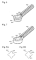
Fig. 6 is a perspective view showing a second modification example of a pivot member. -
Fig. 7 is a perspective view showing a third modification example of a pivot member. -
Figs. 8A and 8B are cross sectional views showing a modification example of a support bar. -
Fig. 9 is a flow chart which shows a production method for a ball joint. -
Fig. 10 is a diagram which shows a ball joint according to a second embodiment. -
Figs. 11A and 11B are views showing a portion of a pivot member according to a second embodiment. -
Figs. 12A and 12B are views showing a portion of a pivot member according to a second embodiment. -
Figs. 13A to 13C are diagrams showing a support bar according to a second embodiment. -
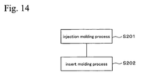
Fig. 14 is a flow chart which shows a production method for a pivot member. -
Reference numeral 10 denotes a ball joint, 100 denotes a ball stud, 110 denotes a stud portion, 120 denotes a ball portion, 210 denotes a ball seat, 212 denotes a recess portion, 220 denotes a housing, 221 denotes an upper portion, 223 denotes a recess portion, 224 denotes a flat portion, 230 denotes a support bar, 231 denotes a bar portion, 232 denotes a protruding ridge, 300 denotes a dust cover, 525 denotes a boss portion, 525a denotes an opening portion, 533 denotes a straight portion, 534 denotes a protruding portion, 535 denotes a flange portion. - An embodiment of the present invention will be explained hereinafter.
Fig. 1 is a diagram which shows a ball joint.Fig. 2 is a diagram showing a condition in which a ball joint is vibrated.Fig. 3 is a perspective view showing a portion of a pivot member.Fig. 4 is a cross sectional view which is taken along line X-X inFig. 3 and which shows a support bar.Fig. 5 is a perspective view showing a first modification example of a pivot member.Fig. 6 is a perspective view showing a second modification example of a pivot member.Fig. 7 is a perspective view showing a third modification example of a pivot member.Figs. 8A and 8B are cross sectional views showing a modification example of a support bar.Fig. 8A is a cross sectional view showing a first modification example of a support bar.Fig. 8B is a cross sectional view showing a second modification example of a support bar. - As shown in
Figs. 1 and 2 , a ball joint 10 is equipped with aball stud 100, apivot member 200, adust cover 300, and the like. Thepivot member 200 has ahousing 220 and the like. The ball joint 10 has theball stud 100 and thepivot member 200 as main components, and it is secured to a plate-like mounting member (not shown in the Figures). Thepivot member 200 universally supports theball stud 100. The ball joint 10 is used for connecting portions of stabilizers or the like. - As shown in
Figs. 1 and 2 ,housings 220 are provided on both sides of asupport bar 230. In a connecting portion of a stabilizer, when mounting directions of thehousings 220 are the same, a phase angle between thehousings 220 is 0 degrees. Thus, as shown inFigs. 1 and 2 , when thehousings 220 on both sides are directed toward an upper side, the phase angle between thehousings 220 is 0 degrees. When thehousing 220 on one side is directed toward an upper side and theother housing 220 on the other side is directed toward a lower side, the phase angle between thehousings 220 is 180 degrees. - The
ball stud 100 is made of a metal and is integrally formed. As shown inFigs. 1 and 2 , theball stud 100 has astud portion 110, aball portion 120, aflange portion 130, ascrew portion 140, a protrudingportion 150, and atapered portion 160. Theball stud 100 is structured such that theball portion 120 is formed at an end portion of thecolumnar stud portion 110. Theball portion 120 has a center positioned on an axis of thestud portion 110. On theball stud 100, theflange portion 130 having a flanged shape is formed at an axial direction middle portion of thestud portion 110, and the protrudingportion 150 is formed for prevention of movement of thedust cover 300. On theball stud 100, at a circumferential surface of a leading end side from theflange portion 130 of the stud portion 110 (that is, a peripheral surface of a side opposite to the ball portion 120), thescrew portion 140 is formed, and the taperedportion 160 is formed at a side of theball portion 120. - The
ball stud 100 is fastened as follows. The leading end portion of theball stud 100, at which thescrew portion 140 is formed, is penetrated into a hole which is formed at the mounting member (not shown in the Figures). A nut (not shown in the Figures) is screwed to thescrew portion 140, so that the leading end portion of theball stud 100 is secured to the mounting member. Thus, theflange portion 130 of theball stud 100 and the nut hold the mounting member, so that theball stud 100 is fastened. - As shown in
Figs. 1 and 2 , thepivot member 200 is equipped with aball seat 210, thehousing 220, and thesupport bar 230. - The
ball seat 210 is made of a hard resin (polyacetal, polybutylene terephthalate, or the like). Theball seat 210 has aflange portion 211, arecess portion 212, and athermal caulking portion 213. Theball seat 210 has a cylindrical shape with a bottom. Theflange portion 211 is formed at an upper end of the cylindrical shape. Regarding theball seat 210, thespherical recess portion 212 is formed at an inner portion thereof, and thethermal caulking portion 213 is formed at an outside bottom surface thereof for securing theball seat 210 to thehousing 220. - The
housing 220 is made of a resin (polyphenylene sulfide, polyether ether ketone, or the like). Thehousing 220 has anupper end portion 221, ahole portion 222, arecess portion 223, and aflat portion 224. Theupper end portion 221 and theflat portion 224 are formed at an upper end of thehousing 220. Therecess portion 223 in which theball seat 210 is provided is formed at an inner portion of thehousing 220. Thehole portion 222, in which thethermal caulking portion 213 of theball seat 210 is inserted, is at a bottom surface of thehousing 220. Thehousing 220 holds theball seat 210 therein. Specifically, thethermal caulking portion 213 of theball seat 210, which is fitted into thehole portion 222, is heated, so that theball seat 210 is secured to thehousing 220. - The
housing 220 is formed so as to have an outer diameter at the upper end side which is larger than an outer diameter of the bottom side. Specifically, the entirety of the peripheral wall of thehousing 220 is formed so as to have a tapered shape, and the outer diameter of thehousing 220 is slightly larger from the bottom side to the upper end side of thehousing 220. - An embodiment in which the outer diameter of the
housing 220 is larger at the upper end side is not limited to this embodiment. For example, as shown inFig. 5 , a portion of the peripheral wall may be formed so as to have a tapered shape. Alternatively, as shown inFig. 6 , a flange portion may be provided at the upper end side of thehousing 220. Alternatively, as shown inFig. 7 , thehousing 220 may have a cylindrical shape. - Since the
housing 220 is formed so as to have an outer diameter of the upper end side which is larger than an outer diameter of the bottom side in this manner, the strength of the upper side of thehousing 220, which may be weak, can be greater. Thus, when a tensile load is applied on thehousing 220 toward an axial direction of thesupport bar 230, thehousing 220 can have the load applied thereto, and breakage of thehousing 220 can be prevented. That is, the strength of thehousing 220 can be greater. The resin used can be reduced, so that weight and cost can be reduced. - As shown in
Figs. 1 to 3 , theflat portion 224 is provided at the upper end of thehousing 220 which is proximate to thesupport bar 230. Theflat portion 224 is provided to be flush with theupper end portion 221. Theupper end portion 221 is formed so as to have a flat contact portion which thedust cover 300 contacts in vibration of theball stud 100. - The entire portion, which the
dust cover 300 contacts in vibration of theball stud 100, is flat by formation of theflat portion 224 and theupper end portion 221. Thus, in vibration of theball stud 100, contact of thedust cover 300 to a protruding portion (a corner portion or the like) can be prevented, and breakage of thedust cover 300 can be prevented. - The
support bar 230 is made of a resin (polyphenylene sulfide, polyether ether ketone, or the like). Thesupport bar 230 is integrally formed with thehousing 220. Thesupport bar 230 is provided at the peripheral wall of thehousing 220 so as to extend in a radial direction of thehousing 220. As shown inFigs. 1 to 3 , thesupport bar 230 has abar portion 231, a protrudingridge 232, and asupport portion 233. Thebar portion 231 is a center portion extending in the axial direction of thesupport bar 230. - In consideration of a die for forming the
housing 220 and thesupport bar 230, when the phase angle is 0 degrees or 180 degrees, the embodiment in which thehousing 220 and thesupport bar 230 are integrally formed is desirable. - Since the
housing 220 and thesupport bar 230 are integrally formed in this manner, when a tensile load, a compressive load, or the like is applied in the axial direction of thesupport bar 230, a boundary portion between thehousing 220 and thesupport bar 230 has the load applied thereto. Thus, when the load is applied in the axial direction of thesupport bar 230, breakage from the boundary portion between thehousing 220 and thesupport bar 230 can be prevented. That is, the ability to support the load in the axial direction of thesupport bar 230 can be improved, and the strength of the ball joint 10 can be improved. As a result, the reliability of the ball joint 10 can be improved. - The protruding
ridges 232 are provided so as to extend in the axial direction of thesupport bar 230. The protrudingridges 232 are integrally formed with thebar portion 231. Plural protrudingridges 232 are provided in a circumferential direction. For example, as shown inFig. 4 , the number of protrudingridges 232 is six. Since the phase angle between thehousings 220 on both ends of thesupport bar 230 is 0 degrees or 180 degrees, a pair of the protrudingridges 232 is provided so that each faces the other in a horizontal direction when opening directions of therecesses 223 of thehousings 220 are upward and downward. - The present invention is not limited to the embodiment in which the number of the protruding
ridges 232 is six. For example, as shown inFigs. 8A and 8B , the number of the protrudingridges 232 may be four. The present invention is not limited to having a valley formed between the protrudingridges Fig. 8A . For example, as shown inFig. 8B , a protrudingportion 232a may be formed between the protrudingridges - For example, the number of the protruding ridges may be eight. In this case, in consideration of easy removal of the support bar from a half divided die, there may be one of eight protruding ridges, which may be an overhang portion that abuts the half divided die and cannot be easily removed therefrom. In this case, the protruding ridge which may be the overhang portion is formed so as to be smaller than the other protruding ridges which may not be an overhang portion. Therefore, the protruding ridge may not function as the overhang portion. Thus, the number of the protruding ridges is not limited to even number, and it may be odd number. The number of the protruding ridges may be plural.
- In this manner, since the protruding
ridges 232 are provided so as to extend, buckling of thesupport bar 230 can be prevented when a load is applied in the axial direction of thesupport bar 230. That is, stiffness of thesupport bar 230 can be improved. The resin used can be reduced, so that the weight and the cost can be reduced. - As shown in
Fig. 3 , thesupport portions 233 are provided at both sides of thebar portion 231 which is proximate to thehousing 220. Thesupport portions 233 are formed so as to have an inner shape formed by drawing a tangential line from the peripheral wall of thehousing 220 in the horizontal direction. Specifically, a pair of the protrudingridges 232 positioned horizontally is formed so as to extend the width thereof. When a load is applied on thehousing 220 or thesupport bar 230 from the horizontal direction, thesupport portions 233 support thehousing 220 or thesupport bar 230. Thus, breakage, which may occur from the boundary portion between thehousing 220 and thesupport bar 230 due to the load, can be prevented. - The shape of the
support portion 233 is not limited to that of this embodiment. For example, the shape of thesupport portion 233 may be formed such that a tangential line drawn from the peripheral wall of thehousing 220 is formed to have a circular arc shape. Thesupport portion 233 may have a shape so as to support thehousing 220 or thesupport bar 230 when a load is applied on thehousing 220 or thesupport bar 230 from the horizontal direction. - As shown in
Figs. 1 and 2 , thedust cover 300 is made of a rubber and has an umbrella shape. Thedust cover 300 is secured as follows. The larger diameter side end of thedust cover 300 is held by theflange portion 211 of theball seat 210 and theupper end portion 221 of thehousing 220, thereby being secured therebetween. The smaller diameter side end of thedust cover 300 is latched by theflange portion 130 of theball stud 100 and movement of the smaller diameter side end thereof is inhibited by the protrudingportion 150, so that the smaller diameter side end thereof is secured thereat. Thus, sealing properties can be provided by thedust cover 300, and infiltration of dust into therecess portion 212 of theball seat 210 can be prevented. As shown inFig. 2 , thedust cover 300 contacts theupper end portion 221 and theflat portion 224 in vibration of theball stud 100. - Regarding the weight of the ball joint 10, for example, one ball joint having a housing and a support bar which are made of a steel material has a weight of 390 grams. When the
support bar 230 has an axial direction length of 325 mm, the weight of thesupport bar 230 is 105grams, and the total weight of thesupport bar 230 is 235 grams. Thus, the weight can be reduced by about 155 grams. - Next, a production method for the ball joint 10 of the first embodiment will be explained with reference to the drawings.
Fig. 9 is a flow chart which shows a production method for a ball joint. - First, in an injection molding process (in step S101), the
housing 220, having thehole portion 222 and therecess portion 223, and thesupport bar 230 are integrally formed by injection using a resin. Next, in a securing process (in step S102), theball seat 210 is inserted into therecess portion 223 of thehousing 220. In the securing process, in a condition in which theball portion 120 of theball stud 100 is press-fitted into therecess portion 212 of theball seat 210, theball seat 210 is press-fitted into therecess portion 223 of thehousing 220. In a thermal caulking process, thethermal caulking portion 213, which is provided at the bottom surface of theball seat 210 inserted into thehole portion 222 formed in the bottom surface of thehousing 220, is caulked by heating. - The ball joint 10 is produced by the above processes.
- The securing process, in which the ball seat is secured in the
recess portion 223 of thehousing 220, is not limited to the embodiment. For example, an adhesive layer may be provided at the recess portion of the housing, and the ball seat may be secured in the recess portion of the housing. - In this production method, in consideration of bending of the
support bar 230, by adjusting a shape of a die for the injection molding process, it is possible for an outer diameter of thesupport bar 230 to be slightly smaller from a center of thesupport bar 230, which is a maximum stress portion, to an end portion thereof. Thus, stress of thebar portion 231 cam be uniform, and the weight of the ball joint 10 can be further reduced. - In the ball joint produced by this production method, the
housing 220 and thesupport bar 230 are integrally formed, when a tensile load, a compressive load, or the like is applied in the axial direction of thesupport bar 230, a boundary portion between thehousing 220 and thesupport bar 230 has the load applied thereto. Thus, when the load is applied in the axial direction of thesupport bar 230, breakage from the boundary portion between thehousing 220 and thesupport bar 230 can be prevented. That is, the ability to support the load in the axial direction of thesupport bar 230 can be improved, and the strength of the ball joint 10 can be improved. As a result, the reliability of the ball joint 10 can be improved. The weight of the ball joint can be reduced. - A second embodiment of the ball joint of the present invention will be explained with reference to the drawings. In the second embodiment of the ball joint, the housing and the support bar of the pivot member of the first embodiment are modified. Thus, constructions of the housing and the support bar of the pivot member will be explained mainly, and explanation of the same components as those in the first embodiment will be omitted.
-
Fig. 10 is a diagram which shows a ball joint according to a second embodiment.Figs. 11A and 11B are views showing a portion of a pivot member according to a second embodiment.Fig. 11A is a perspective view of the portion of the pivot member.Fig. 11B is a side view of the portion of the pivot member.Figs. 12A and 12B are views showing a portion of a pivot member according to a second embodiment.Fig. 12A is a perspective view of the portion of the pivot member.Fig. 12B is a side view of the portion of the pivot member.Figs. 13A to 13C are diagrams showing a support bar according to a second embodiment.Fig. 13A is a perspective view of the support bar. -
Fig. 13B is a side view of the support bar.Fig. 13C is a conceptual diagram of the support bar. - The
housing 520 is made of a resin (polyphenylene sulfide, polyether ether ketone, or the like). As shown inFigs. 11A and 11B and 12A and 12B , thehousing 520 has anupper portion 521, arecess portion 523, aflat portion 524, and aboss portion 525. - The
boss portion 525 is provided at a side of thesupport bar 530. Theboss portion 525 has anopening portion 525a. Theopening portion 525a opens at a side surface of thehousing 520. A leading end portion of thesupport bar 530 is connected to theopening portion 525a, and theboss portion 525 is a portion for connecting thehousing 520 and asupport bar 530. Theopening portion 525a covers the leading end portion of thesupport bar 530, and has the same shape as that of he leading end portion of thesupport bar 530. - The
boss portion 525 is formed so as to closely contact and cover the leading end portion of thesupport bar 530, so that theboss portion 525 has a larger outer diameter, and theboss portion 525 is higher than theupper portion 521 of thehousing 520. Thus, in thehousing 520, theflat portion 524 is provided to have a shape cut from an upper end of theboss portion 525 to theupper end portion 521 of thehousing 520. - The
support bar 530 is made of a resin (polyphenylene sulfide, polyether ether ketone, or the like). Thesupport bar 530 is separately formed from thehousing 520. AS shown inFigs. 11A and 11B and 12A and 12B , thesupport bar 530 is provided at the peripheral wall of thehousing 520 so as to extend in a radial direction of thehousing 520. As shown inFigs. 12A and 12B and13A to 13C , thesupport bar 530 has abar portion 531, a protrudingridge 532, astraight portion 533, a protrudingportion 534, and aflange portion 535. - In consideration of a die for forming the
housing 520 and thesupport bar 530, when the phase angle is 0 degrees or 180 degrees, the embodiment in which thehousing 520 and thesupport bar 530 are separately formed is desirable. - The
straight portion 533 is positioned so as not to be covered with theopening portion 525a of theboss portion 525 proximate to the leading end of thesupport bar 530. Specifically, thestraight portion 533 is formed at a side of thehousing 520 and within a predetermined range in an axial direction of thesupport bar 530 which is apart from theboss portion 525. Thestraight portion 533 has a columnar shape having an outer diameter equal to that of the circumscribed circle circumscribed on the protrudingridge 532. - The protruding
portion 534 is positioned so as to be covered with theopening portion 525a of theboss portion 525 between thestraight portion 533 and theflange portion 535. Specifically, theopening portion 525a is formed so as to closely contact and cover the entire periphery of the protrudingportion 534. The protrudingportion 534 is formed to have the same shape as that of protrudingridge 532 of thebar portion 531. - Since the protruding
portion 534 is provided in this manner, when a torsional load is applied on thehousing 520 or thesupport bar 530, rotation of thehousing 520 or thesupport bar 530 with respect to each other is prevented. Thus, when a torsional load is applied on thehousing 520 or thesupport bar 530, change of the phase angle between thehousings 520 is prevented, and the function of the ball joint 10 can be maintained. - The
flange portion 535 is provided at a leading end portion of thebar portion 531. Theflange portion 535 is formed to be flanged. The entire periphery of theflange portion 535 is provided so as to be covered with theopening portion 525a. That is, theopening portion 525a is formed so as to closely contact and cover the entire periphery of theflange portion 535. When a tensile load is applied in the axial direction of thesupport bar 530, removal of thesupport bar 530 from theboss portion 525 of thehousing 520 is prevented. - As shown in
Figs. 13A to 13C , when reference symbol Ab denotes a cross sectional area of thesupport bar 530 and reference symbol Dv denotes a root diameter between the protrudingridges flange portion 535 satisfies the following Equation 1.
- As shown in
Fig. 13C , the area Af of theflange portion 535, which is other than an area of a circumscribed circle circumscribed on theflange portion 535, satisfies the following Equation 2.
- The
flange portion 535 is formed so as to satisfy the Equations 1 and 2, so that easy breakage of theflange portion 535 can be prevented, and removal of thesupport bar 530 from theboss portion 525 of thehousing 520, which may be caused by a tensile load, can be prevented. - In this embodiment, in order that the
flange portion 535 may not be larger than the size of thehousing 520 of the axial direction of theball stud 100, theflange portion 535 has an outer shape such that upper and lower ends of circular shape are cut. Alternatively, for example, when the Equation 2 is satisfied, the outer shape of theflange portion 535 is a circular shape or the like. - In this embodiment, since the
housing 520 and thesupport bar 530 are mechanically engaged with each other, easy separation of thesupport bar 530 from thehousing 520 can be prevented. Since thehousing 520 and thesupport bar 530 are made of the same material, generation of backlash, crack, or the like, in which contact surfaces of thehousing 520 and thesupport bar 530 may be separated from each other due to difference in thermal expansion coefficient, can be prevented. Thus, the reliability of the ball joint 10 can be improved. - Next, a production method for the pivot member of the second embodiment will be explained.
Fig. 14 is a flow chart which shows a production method for the pivot member. - First, in an injection molding process (in step S201), the
support bar 530, which has thestraight portion 533, theflange portion 535, and the like, are formed by injection using a resin. Next, in a insert molding process (in step S202), thehousing 520 is formed by injection using a resin such that the leading end portion of thesupport bar 530 is covered with the resin. In this insert molding process, first, the leading end portion of thesupport bar 530, which includes the protrudingportion 534 and theflange portion 535, is inserted into a die. Next, thesupport bar 530 is supported by supporting thestraight portion 533, and thehousing 520 is formed by the resin such that the leading end portion of thesupport bar 530 is covered with theboss portion 525. Thepivot member 500 is produced by the above processes. - In this production method, when the
housing 520 is formed at the leading end portion of thesupport bar 530 after formation of thesupport bar 530, thesupport bar 530 is supported by supporting thestraight portion 533, and thehousing 520 can be formed. Thus, when thehousing 520 is formed, thesupport bar 530 is easily supported, so that change of the relative position of thesupport bar 530 to the die for forming thehousing 520 can be prevented. Therefore, leakage of the resin from the die for forming thehousing 520 can be prevented. - The end portion of the
support bar 530 can be strongly compressed and secured by molding shrinkage of thehousing 520 formed after the formation of thesupport bar 530. Thus, generation of backlash, in which contact surfaces of thehousing 520 and thesupport bar 530 may be separated from each other, can be prevented, so that the reliability of the ball joint 10 can be improved. - The present invention can be used for stabilizers, which are provided to vehicles (automobiles and the like), or the like.
Claims (8)
- A ball joint comprising:a ball stud having a columnar stud portion and a ball portion which has a spherical side surface and a center positioned on an axis of the stud portion;a ball seat which is made of a resin and has a spherical recess portion into which the ball portion is relatively rotatably and slidably fitted;a housing which is made of a resin and holds the ball seat therein; anda support bar which is integrally formed with the housing, whereinthe support bar has a bar portion which is a center portion extending along an axis of the support bar.
- A ball joint comprising:a ball stud having a columnar stud portion and a ball portion which has a spherical side surface and a center positioned on an axis of the stud portion;a ball seat which is made of a resin and has a spherical recess portion into which the ball portion is rotatably and slidably fitted;a housing which is made of a resin and holds the ball seat therein; anda support bar which is connected with the housing, whereinthe housing has a boss portion having an opening portion which opens at a side surface of the housing,the support bar has a bar portion and a flange portion, the bar portion being a center portion extending along an axis of the support bar, the flange portion formed at a leading end portion of the bar portion so as to have a flanged shape, andthe support bar is connected with the boss portion so that the opening portion is formed in close contact with and covers an entire periphery of the flange portion.
- A ball joint according to claim 1 or 2, wherein
the support bar extends in an axial direction of the support bar and has plural protruding ridges which are integrally formed with the bar portion in a circumferential direction of the support bar. - A ball joint according to claim 2, wherein
the support bar has plural protruding portions at the flange portion of the bar portion, and
the opening portion is formed in close contact with and covers entire peripheries of the protruding portions. - A ball joint according to claim 2, wherein
the support bar has a straight portion formed at a side of the housing and within a predetermined range in an axial direction of the support bar, the axial direction being apart from the boss portion. - A ball joint according to claim 1 or 2, wherein
the housing is formed to have an upper end side and a bottom side, the upper end side having an outer diameter larger than that of the bottom side. - A ball joint according to claim 1 or 2, wherein
the ball joint comprising:a dust cover which has an end contacting the stud portion and the other end contacting an upper end of the housing;an upper end portion which is formed at the upper end of the housing so as to have a flat contact portion which the dust cover contacts when the ball stud vibrates ; anda flat portion which is formed at a side of the support bar so as to be flush with the upper end portion. - A production method for a ball joint, comprising:injection molding in which a support bar having a flange portion and a straight portion is formed by injection using a resin; andinsert molding in which the straight portion is supported and a housing having a boss portion is formed by injection using a resin so that the boss portion covers a leading end portion of the support bar which includes the flange portion.
Applications Claiming Priority (2)
| Application Number | Priority Date | Filing Date | Title |
|---|---|---|---|
| JP2008108675A JP4933476B2 (en) | 2008-04-18 | 2008-04-18 | Ball joint |
| PCT/JP2009/057577 WO2009128472A1 (en) | 2008-04-18 | 2009-04-15 | Ball joint and method of manufacturing the same |
Publications (3)
| Publication Number | Publication Date |
|---|---|
| EP2270344A1 true EP2270344A1 (en) | 2011-01-05 |
| EP2270344A4 EP2270344A4 (en) | 2011-08-24 |
| EP2270344B1 EP2270344B1 (en) | 2018-05-30 |
Family
ID=41199160
Family Applications (1)
| Application Number | Title | Priority Date | Filing Date |
|---|---|---|---|
| EP09732611.0A Active EP2270344B1 (en) | 2008-04-18 | 2009-04-15 | Ball joint and method of manufacturing the same |
Country Status (8)
| Country | Link |
|---|---|
| US (1) | US8376647B2 (en) |
| EP (1) | EP2270344B1 (en) |
| JP (1) | JP4933476B2 (en) |
| KR (1) | KR101539480B1 (en) |
| CN (1) | CN102007309B (en) |
| BR (1) | BRPI0911111A2 (en) |
| ES (1) | ES2682460T3 (en) |
| WO (1) | WO2009128472A1 (en) |
Cited By (4)
| Publication number | Priority date | Publication date | Assignee | Title |
|---|---|---|---|---|
| WO2013127582A1 (en) * | 2012-02-28 | 2013-09-06 | Zf Friedrichshafen Ag | Connection arrangement for a motor vehicle wheel suspension |
| EP3199389A1 (en) * | 2016-01-26 | 2017-08-02 | ZF Friedrichshafen AG | Suspension arm comprising a glued joint |
| WO2018197131A1 (en) * | 2017-04-24 | 2018-11-01 | Zf Friedrichshafen Ag | Axle strut |
| EP3524450B1 (en) * | 2018-02-09 | 2022-10-05 | Toyota Jidosha Kabushiki Kaisha | Arm component and manufacturing method therefor |
Families Citing this family (24)
| Publication number | Priority date | Publication date | Assignee | Title |
|---|---|---|---|---|
| ES2537900T3 (en) * | 2009-06-30 | 2015-06-15 | Trw Automotive Gmbh | Ball joint |
| US8714571B2 (en) * | 2010-03-16 | 2014-05-06 | Automann Inc. | Torque rod |
| JP2011247338A (en) * | 2010-05-26 | 2011-12-08 | Nhk Spring Co Ltd | Stabilizer link and method for producing the same |
| JP5189145B2 (en) | 2010-08-23 | 2013-04-24 | 日本発條株式会社 | Stabilink and manufacturing method thereof |
| JP5826508B2 (en) * | 2011-04-14 | 2015-12-02 | 日本発條株式会社 | Manufacturing method of stabilizer link |
| JP5150750B2 (en) * | 2011-06-10 | 2013-02-27 | 日本発條株式会社 | Ball joint and manufacturing method thereof |
| JP5709665B2 (en) * | 2011-06-20 | 2015-04-30 | 日本発條株式会社 | Stabilink and manufacturing method thereof |
| US8757648B1 (en) * | 2013-05-03 | 2014-06-24 | Mevotech Lp | Control arm assembly with ball joint for automotive suspension |
| DE102014213111B4 (en) * | 2013-07-15 | 2020-06-18 | Ford Global Technologies, Llc | Device for stabilizing a motor vehicle against roll movements |
| US9616725B2 (en) * | 2013-10-02 | 2017-04-11 | Nhk Spring Co., Ltd. | Suspension arm member |
| JP6349573B2 (en) * | 2013-12-27 | 2018-07-04 | 三井金属アクト株式会社 | Striker |
| DE102014220443B4 (en) * | 2014-10-09 | 2021-12-23 | Ford Global Technologies, Llc | Handlebars for connecting a vehicle wheel to a vehicle and vehicle wheel suspension |
| KR101732063B1 (en) | 2015-04-29 | 2017-05-08 | 주식회사 일진 | Hybrid Arm With Ball Joint Integrated For Vehicle And The Method Thereof |
| JP6228996B2 (en) * | 2016-01-21 | 2017-11-08 | 日本発條株式会社 | Torque tuning method and ball joint |
| JP6234491B2 (en) * | 2016-02-10 | 2017-11-22 | 日本発條株式会社 | Ball joint manufacturing method and stabilizer link manufacturing method |
| JP6832206B2 (en) * | 2017-03-29 | 2021-02-24 | 日本発條株式会社 | Ball joint and stabilizer link using it |
| IL251923A0 (en) * | 2017-04-25 | 2017-07-31 | Duke Airborne Systems Ltd | A bearing assembly and uses thereof |
| US10808792B2 (en) | 2018-07-18 | 2020-10-20 | Honda Motor Co, Ltd. | Apparatus for shielding vehicle component |
| FR3084007B1 (en) * | 2018-07-19 | 2022-01-14 | Arianegroup Sas | PARTIALLY CURED HEAT-SETTING CONNECTOR AND METHODS OF MAKING AND ASSEMBLING SUCH CONNECTOR |
| DE102019204659A1 (en) * | 2019-04-02 | 2020-10-08 | Zf Friedrichshafen Ag | Ball joint for a chassis of a vehicle and method for producing such a ball joint |
| JP7175856B2 (en) * | 2019-07-17 | 2022-11-21 | 日本発條株式会社 | BALL SEAT, BALL JOINT AND METHOD OF MANUFACTURING BALL JOINT |
| US11859658B2 (en) * | 2021-08-17 | 2024-01-02 | Cnh Industrial America Llc | Steering sensor drive for articulating ball joint |
| KR102939295B1 (en) * | 2023-12-28 | 2026-03-13 | 주식회사 일진 | Link for vehicle and manufacturing method thereof |
| CN119408357B (en) * | 2024-10-22 | 2025-06-06 | 宁波优适捷传动件有限公司 | An assembly detection method for automobile tie rod structure |
Family Cites Families (38)
| Publication number | Priority date | Publication date | Assignee | Title |
|---|---|---|---|---|
| US2589820A (en) * | 1948-09-08 | 1952-03-18 | Anton W Konchan | Shock absorber link |
| JPS5727325B2 (en) * | 1973-11-20 | 1982-06-10 | ||
| US4225261A (en) * | 1979-02-12 | 1980-09-30 | Atwood Vacuum Machine Company | Ball socket assembly with resilient locking key |
| US4311405A (en) * | 1979-10-22 | 1982-01-19 | Illinois Tool Works Inc. | Swivel connector |
| JPS5666527U (en) * | 1979-10-29 | 1981-06-03 | ||
| JPS6269620A (en) | 1985-09-24 | 1987-03-30 | Anelva Corp | Plasma processor |
| JPH0343457Y2 (en) * | 1985-10-23 | 1991-09-11 | ||
| JPH01126413A (en) * | 1987-11-09 | 1989-05-18 | Tokai Rubber Ind Ltd | Connecting rod made of resin |
| DE3843330A1 (en) * | 1988-12-22 | 1990-07-05 | Ishikawa Tekko Kk | Cast insert |
| JPH039113A (en) * | 1989-03-22 | 1991-01-17 | Yorozu:Kk | Ball joint and its manufacture |
| US5092703A (en) * | 1989-03-22 | 1992-03-03 | Yorozu Manufacturing Corporation | Ball joint and method of manufacturing the same |
| JPH0366913A (en) * | 1989-08-03 | 1991-03-22 | Ishikawa Tekko Kk | Ball joint |
| JP3004745B2 (en) * | 1991-02-14 | 2000-01-31 | オイレス工業株式会社 | Ball joint for stabilizer |
| US5277860A (en) * | 1992-09-03 | 1994-01-11 | Sinclair William S | Process for making an all-plastic rod end |
| US5615967A (en) * | 1994-06-03 | 1997-04-01 | Maclean-Fogg Company | Ball joint link |
| JP3274937B2 (en) * | 1994-06-29 | 2002-04-15 | 株式会社ショーワ | Ball joint |
| JP3329137B2 (en) * | 1995-04-25 | 2002-09-30 | 株式会社ニフコ | Ball joint |
| DE19542071C2 (en) * | 1995-11-11 | 2000-03-30 | Trw Fahrwerksyst Gmbh & Co | Ball joint |
| US5947627A (en) * | 1996-02-14 | 1999-09-07 | Chuouhatsu-Jo Kabushiki Kaisha | Ball joint assembly having an integrally molded unitary or molded holder for the ball stud and link rod |
| US6109816A (en) * | 1996-09-30 | 2000-08-29 | Bridgestone Corporation | Stabilizer link rod, and method of manufacturing same |
| JPH10151931A (en) * | 1996-09-30 | 1998-06-09 | Bridgestone Corp | Link rod for stabilizer and manufacture thereof |
| JPH11338571A (en) * | 1998-05-28 | 1999-12-10 | Musashi Seimitsu Ind Co Ltd | Joint device for steering |
| JP2000081025A (en) * | 1998-09-07 | 2000-03-21 | Bridgestone Corp | Ball joint and manufacture thereof |
| US6161451A (en) * | 1999-01-18 | 2000-12-19 | Maclean-Fogg Company | Link assembly |
| JP2000310216A (en) * | 1999-02-25 | 2000-11-07 | Somic Ishikawa:Kk | Ball joint and joint device |
| JP2000309214A (en) * | 1999-04-26 | 2000-11-07 | Bridgestone Corp | Ball joint rod made of resin |
| US6698963B1 (en) * | 2000-10-12 | 2004-03-02 | Illinois Tool Works Inc. | Ball and socket joint and method therefor |
| JP4201238B2 (en) * | 2001-04-04 | 2008-12-24 | 日本発條株式会社 | Ball joint and method of manufacturing the same |
| US20060039748A1 (en) * | 2002-06-07 | 2006-02-23 | Ruhlander Gregory P | Arrangement for connecting a rod end to a headed pin and method of manufacture |
| DE10231014B4 (en) * | 2002-07-09 | 2009-10-01 | ZF Lemförder GmbH | Pendulum support with integrated ball joint |
| US7017224B2 (en) * | 2002-07-19 | 2006-03-28 | Valeo Electrical Systems, Inc. | Windshield wiper drive linkage arm with interior grooves |
| JP3862669B2 (en) * | 2003-04-16 | 2006-12-27 | Thk株式会社 | Manufacturing method of spherical bearing |
| WO2005042188A1 (en) * | 2003-10-20 | 2005-05-12 | Magna International, Inc. | Hybrid component |
| US7520691B2 (en) * | 2004-06-24 | 2009-04-21 | ZF Lemförder Metallwaren AG | Protected stabilizer link or tie rod and ball race protecting cap |
| DE102006030099B4 (en) * | 2006-06-28 | 2008-10-16 | Zf Friedrichshafen Ag | Plastic rocker pendulum |
| EP1911612A1 (en) * | 2006-10-13 | 2008-04-16 | Industria Auxiliar Alavesa, S.A. (Inauxa) | Suspension arm for a motor vehicle wheel suspension |
| DE102007038494A1 (en) * | 2007-08-14 | 2009-02-19 | Zf Friedrichshafen Ag | Coupling rod for a vehicle |
| JP5284018B2 (en) * | 2008-09-09 | 2013-09-11 | 日本発條株式会社 | Ball joint |
-
2008
- 2008-04-18 JP JP2008108675A patent/JP4933476B2/en not_active Expired - Fee Related
-
2009
- 2009-04-15 KR KR1020107024540A patent/KR101539480B1/en active Active
- 2009-04-15 EP EP09732611.0A patent/EP2270344B1/en active Active
- 2009-04-15 CN CN200980113613.3A patent/CN102007309B/en active Active
- 2009-04-15 WO PCT/JP2009/057577 patent/WO2009128472A1/en not_active Ceased
- 2009-04-15 BR BRPI0911111A patent/BRPI0911111A2/en not_active IP Right Cessation
- 2009-04-15 ES ES09732611.0T patent/ES2682460T3/en active Active
- 2009-04-15 US US12/935,990 patent/US8376647B2/en not_active Expired - Fee Related
Cited By (5)
| Publication number | Priority date | Publication date | Assignee | Title |
|---|---|---|---|---|
| WO2013127582A1 (en) * | 2012-02-28 | 2013-09-06 | Zf Friedrichshafen Ag | Connection arrangement for a motor vehicle wheel suspension |
| US9085214B2 (en) | 2012-02-28 | 2015-07-21 | Zf Friedrichshafen, Ag | Connection arrangement for a motor vehicle wheel suspension |
| EP3199389A1 (en) * | 2016-01-26 | 2017-08-02 | ZF Friedrichshafen AG | Suspension arm comprising a glued joint |
| WO2018197131A1 (en) * | 2017-04-24 | 2018-11-01 | Zf Friedrichshafen Ag | Axle strut |
| EP3524450B1 (en) * | 2018-02-09 | 2022-10-05 | Toyota Jidosha Kabushiki Kaisha | Arm component and manufacturing method therefor |
Also Published As
| Publication number | Publication date |
|---|---|
| WO2009128472A1 (en) | 2009-10-22 |
| US20110033226A1 (en) | 2011-02-10 |
| CN102007309B (en) | 2016-07-06 |
| EP2270344A4 (en) | 2011-08-24 |
| KR20100134083A (en) | 2010-12-22 |
| US8376647B2 (en) | 2013-02-19 |
| ES2682460T3 (en) | 2018-09-20 |
| JP2009257507A (en) | 2009-11-05 |
| CN102007309A (en) | 2011-04-06 |
| KR101539480B1 (en) | 2015-07-24 |
| EP2270344B1 (en) | 2018-05-30 |
| JP4933476B2 (en) | 2012-05-16 |
| BRPI0911111A2 (en) | 2015-10-06 |
Similar Documents
| Publication | Publication Date | Title |
|---|---|---|
| US8376647B2 (en) | Ball joint and production method therefor | |
| US9056538B2 (en) | Stabilizer link and manufacturing method therefor | |
| KR101183812B1 (en) | Ball and socket joint and method for producing the same | |
| CN103608595B (en) | Stabilizer link and manufacturing method thereof | |
| EP2336582B1 (en) | Ball joint and method of manufacturing same | |
| EP2592288B1 (en) | Ball joint and method for producing ball joint | |
| US20090202184A1 (en) | Bush bearing with reduced installation space | |
| WO2011148792A1 (en) | Stabilizer link and method for producing same | |
| CN110382886A (en) | Pod component | |
| KR20080085004A (en) | Method of manufacturing ball joints and joint housings | |
| KR20180110119A (en) | Ball joint and stabilizer link using it | |
| JP2007161146A (en) | Stabilizer bush | |
| JP6264652B2 (en) | Automotive knuckle | |
| US20050241860A1 (en) | Elastomer joint | |
| JP6136779B2 (en) | Vehicle door hinge device | |
| JP2009190065A (en) | Caulking structure using color members | |
| JP3888551B2 (en) | Vehicle door hinge mounting structure | |
| CN213892662U (en) | Connection structure and vehicle of sub vehicle frame and automobile body | |
| JP2005061537A (en) | Ball joint | |
| JP5150750B2 (en) | Ball joint and manufacturing method thereof | |
| CN109017158A (en) | Bloster and its manufacturing method for commercial vehicle | |
| JPS6199715A (en) | Ball joint | |
| JP2009216135A (en) | Automobile cylindrical vibration isolator | |
| US20250297660A1 (en) | Elastic bearing element | |
| JP4699294B2 (en) | Vibration isolator |
Legal Events
| Date | Code | Title | Description |
|---|---|---|---|
| PUAI | Public reference made under article 153(3) epc to a published international application that has entered the european phase |
Free format text: ORIGINAL CODE: 0009012 |
|
| 17P | Request for examination filed |
Effective date: 20101118 |
|
| AK | Designated contracting states |
Kind code of ref document: A1 Designated state(s): AT BE BG CH CY CZ DE DK EE ES FI FR GB GR HR HU IE IS IT LI LT LU LV MC MK MT NL NO PL PT RO SE SI SK TR |
|
| AX | Request for extension of the european patent |
Extension state: AL BA RS |
|
| DAX | Request for extension of the european patent (deleted) | ||
| A4 | Supplementary search report drawn up and despatched |
Effective date: 20110721 |
|
| RIC1 | Information provided on ipc code assigned before grant |
Ipc: B60G 21/055 20060101ALI20110715BHEP Ipc: B60G 7/02 20060101ALI20110715BHEP Ipc: F16C 11/06 20060101AFI20110715BHEP |
|
| 17Q | First examination report despatched |
Effective date: 20160322 |
|
| REG | Reference to a national code |
Ref country code: DE Ref legal event code: R079 Ref document number: 602009052522 Country of ref document: DE Free format text: PREVIOUS MAIN CLASS: F16C0011060000 Ipc: B60G0007000000 |
|
| RIC1 | Information provided on ipc code assigned before grant |
Ipc: F16C 7/02 20060101ALI20171004BHEP Ipc: B60G 7/00 20060101AFI20171004BHEP Ipc: F16C 11/06 20060101ALI20171004BHEP |
|
| GRAP | Despatch of communication of intention to grant a patent |
Free format text: ORIGINAL CODE: EPIDOSNIGR1 |
|
| STAA | Information on the status of an ep patent application or granted ep patent |
Free format text: STATUS: GRANT OF PATENT IS INTENDED |
|
| INTG | Intention to grant announced |
Effective date: 20171116 |
|
| GRAS | Grant fee paid |
Free format text: ORIGINAL CODE: EPIDOSNIGR3 |
|
| GRAA | (expected) grant |
Free format text: ORIGINAL CODE: 0009210 |
|
| STAA | Information on the status of an ep patent application or granted ep patent |
Free format text: STATUS: THE PATENT HAS BEEN GRANTED |
|
| RAP1 | Party data changed (applicant data changed or rights of an application transferred) |
Owner name: NHK SPRING CO., LTD. |
|
| RIN1 | Information on inventor provided before grant (corrected) |
Inventor name: KURODA, SHIGERU |
|
| AK | Designated contracting states |
Kind code of ref document: B1 Designated state(s): AT BE BG CH CY CZ DE DK EE ES FI FR GB GR HR HU IE IS IT LI LT LU LV MC MK MT NL NO PL PT RO SE SI SK TR |
|
| REG | Reference to a national code |
Ref country code: GB Ref legal event code: FG4D |
|
| REG | Reference to a national code |
Ref country code: CH Ref legal event code: EP |
|
| REG | Reference to a national code |
Ref country code: AT Ref legal event code: REF Ref document number: 1003234 Country of ref document: AT Kind code of ref document: T Effective date: 20180615 |
|
| REG | Reference to a national code |
Ref country code: IE Ref legal event code: FG4D |
|
| REG | Reference to a national code |
Ref country code: DE Ref legal event code: R096 Ref document number: 602009052522 Country of ref document: DE |
|
| REG | Reference to a national code |
Ref country code: ES Ref legal event code: FG2A Ref document number: 2682460 Country of ref document: ES Kind code of ref document: T3 Effective date: 20180920 |
|
| REG | Reference to a national code |
Ref country code: NL Ref legal event code: MP Effective date: 20180530 |
|
| REG | Reference to a national code |
Ref country code: LT Ref legal event code: MG4D |
|
| PG25 | Lapsed in a contracting state [announced via postgrant information from national office to epo] |
Ref country code: SE Free format text: LAPSE BECAUSE OF FAILURE TO SUBMIT A TRANSLATION OF THE DESCRIPTION OR TO PAY THE FEE WITHIN THE PRESCRIBED TIME-LIMIT Effective date: 20180530 Ref country code: LT Free format text: LAPSE BECAUSE OF FAILURE TO SUBMIT A TRANSLATION OF THE DESCRIPTION OR TO PAY THE FEE WITHIN THE PRESCRIBED TIME-LIMIT Effective date: 20180530 Ref country code: NO Free format text: LAPSE BECAUSE OF FAILURE TO SUBMIT A TRANSLATION OF THE DESCRIPTION OR TO PAY THE FEE WITHIN THE PRESCRIBED TIME-LIMIT Effective date: 20180830 Ref country code: BG Free format text: LAPSE BECAUSE OF FAILURE TO SUBMIT A TRANSLATION OF THE DESCRIPTION OR TO PAY THE FEE WITHIN THE PRESCRIBED TIME-LIMIT Effective date: 20180830 Ref country code: FI Free format text: LAPSE BECAUSE OF FAILURE TO SUBMIT A TRANSLATION OF THE DESCRIPTION OR TO PAY THE FEE WITHIN THE PRESCRIBED TIME-LIMIT Effective date: 20180530 Ref country code: CY Free format text: LAPSE BECAUSE OF FAILURE TO SUBMIT A TRANSLATION OF THE DESCRIPTION OR TO PAY THE FEE WITHIN THE PRESCRIBED TIME-LIMIT Effective date: 20180530 |
|
| PG25 | Lapsed in a contracting state [announced via postgrant information from national office to epo] |
Ref country code: LV Free format text: LAPSE BECAUSE OF FAILURE TO SUBMIT A TRANSLATION OF THE DESCRIPTION OR TO PAY THE FEE WITHIN THE PRESCRIBED TIME-LIMIT Effective date: 20180530 Ref country code: HR Free format text: LAPSE BECAUSE OF FAILURE TO SUBMIT A TRANSLATION OF THE DESCRIPTION OR TO PAY THE FEE WITHIN THE PRESCRIBED TIME-LIMIT Effective date: 20180530 Ref country code: GR Free format text: LAPSE BECAUSE OF FAILURE TO SUBMIT A TRANSLATION OF THE DESCRIPTION OR TO PAY THE FEE WITHIN THE PRESCRIBED TIME-LIMIT Effective date: 20180831 |
|
| REG | Reference to a national code |
Ref country code: AT Ref legal event code: MK05 Ref document number: 1003234 Country of ref document: AT Kind code of ref document: T Effective date: 20180530 |
|
| PG25 | Lapsed in a contracting state [announced via postgrant information from national office to epo] |
Ref country code: NL Free format text: LAPSE BECAUSE OF FAILURE TO SUBMIT A TRANSLATION OF THE DESCRIPTION OR TO PAY THE FEE WITHIN THE PRESCRIBED TIME-LIMIT Effective date: 20180530 |
|
| PG25 | Lapsed in a contracting state [announced via postgrant information from national office to epo] |
Ref country code: AT Free format text: LAPSE BECAUSE OF FAILURE TO SUBMIT A TRANSLATION OF THE DESCRIPTION OR TO PAY THE FEE WITHIN THE PRESCRIBED TIME-LIMIT Effective date: 20180530 Ref country code: SK Free format text: LAPSE BECAUSE OF FAILURE TO SUBMIT A TRANSLATION OF THE DESCRIPTION OR TO PAY THE FEE WITHIN THE PRESCRIBED TIME-LIMIT Effective date: 20180530 Ref country code: DK Free format text: LAPSE BECAUSE OF FAILURE TO SUBMIT A TRANSLATION OF THE DESCRIPTION OR TO PAY THE FEE WITHIN THE PRESCRIBED TIME-LIMIT Effective date: 20180530 Ref country code: EE Free format text: LAPSE BECAUSE OF FAILURE TO SUBMIT A TRANSLATION OF THE DESCRIPTION OR TO PAY THE FEE WITHIN THE PRESCRIBED TIME-LIMIT Effective date: 20180530 Ref country code: PL Free format text: LAPSE BECAUSE OF FAILURE TO SUBMIT A TRANSLATION OF THE DESCRIPTION OR TO PAY THE FEE WITHIN THE PRESCRIBED TIME-LIMIT Effective date: 20180530 Ref country code: RO Free format text: LAPSE BECAUSE OF FAILURE TO SUBMIT A TRANSLATION OF THE DESCRIPTION OR TO PAY THE FEE WITHIN THE PRESCRIBED TIME-LIMIT Effective date: 20180530 Ref country code: CZ Free format text: LAPSE BECAUSE OF FAILURE TO SUBMIT A TRANSLATION OF THE DESCRIPTION OR TO PAY THE FEE WITHIN THE PRESCRIBED TIME-LIMIT Effective date: 20180530 |
|
| PG25 | Lapsed in a contracting state [announced via postgrant information from national office to epo] |
Ref country code: IT Free format text: LAPSE BECAUSE OF FAILURE TO SUBMIT A TRANSLATION OF THE DESCRIPTION OR TO PAY THE FEE WITHIN THE PRESCRIBED TIME-LIMIT Effective date: 20180530 |
|
| REG | Reference to a national code |
Ref country code: DE Ref legal event code: R097 Ref document number: 602009052522 Country of ref document: DE |
|
| PLBE | No opposition filed within time limit |
Free format text: ORIGINAL CODE: 0009261 |
|
| STAA | Information on the status of an ep patent application or granted ep patent |
Free format text: STATUS: NO OPPOSITION FILED WITHIN TIME LIMIT |
|
| 26N | No opposition filed |
Effective date: 20190301 |
|
| PG25 | Lapsed in a contracting state [announced via postgrant information from national office to epo] |
Ref country code: SI Free format text: LAPSE BECAUSE OF FAILURE TO SUBMIT A TRANSLATION OF THE DESCRIPTION OR TO PAY THE FEE WITHIN THE PRESCRIBED TIME-LIMIT Effective date: 20180530 |
|
| REG | Reference to a national code |
Ref country code: CH Ref legal event code: PL |
|
| REG | Reference to a national code |
Ref country code: BE Ref legal event code: MM Effective date: 20190430 |
|
| GBPC | Gb: european patent ceased through non-payment of renewal fee |
Effective date: 20190415 |
|
| PG25 | Lapsed in a contracting state [announced via postgrant information from national office to epo] |
Ref country code: LU Free format text: LAPSE BECAUSE OF NON-PAYMENT OF DUE FEES Effective date: 20190415 Ref country code: MC Free format text: LAPSE BECAUSE OF FAILURE TO SUBMIT A TRANSLATION OF THE DESCRIPTION OR TO PAY THE FEE WITHIN THE PRESCRIBED TIME-LIMIT Effective date: 20180530 |
|
| PG25 | Lapsed in a contracting state [announced via postgrant information from national office to epo] |
Ref country code: CH Free format text: LAPSE BECAUSE OF NON-PAYMENT OF DUE FEES Effective date: 20190430 Ref country code: LI Free format text: LAPSE BECAUSE OF NON-PAYMENT OF DUE FEES Effective date: 20190430 Ref country code: GB Free format text: LAPSE BECAUSE OF NON-PAYMENT OF DUE FEES Effective date: 20190415 |
|
| PG25 | Lapsed in a contracting state [announced via postgrant information from national office to epo] |
Ref country code: BE Free format text: LAPSE BECAUSE OF NON-PAYMENT OF DUE FEES Effective date: 20190430 |
|
| PG25 | Lapsed in a contracting state [announced via postgrant information from national office to epo] |
Ref country code: TR Free format text: LAPSE BECAUSE OF FAILURE TO SUBMIT A TRANSLATION OF THE DESCRIPTION OR TO PAY THE FEE WITHIN THE PRESCRIBED TIME-LIMIT Effective date: 20180530 |
|
| PG25 | Lapsed in a contracting state [announced via postgrant information from national office to epo] |
Ref country code: IE Free format text: LAPSE BECAUSE OF NON-PAYMENT OF DUE FEES Effective date: 20190415 |
|
| PG25 | Lapsed in a contracting state [announced via postgrant information from national office to epo] |
Ref country code: PT Free format text: LAPSE BECAUSE OF FAILURE TO SUBMIT A TRANSLATION OF THE DESCRIPTION OR TO PAY THE FEE WITHIN THE PRESCRIBED TIME-LIMIT Effective date: 20181001 |
|
| PG25 | Lapsed in a contracting state [announced via postgrant information from national office to epo] |
Ref country code: IS Free format text: LAPSE BECAUSE OF FAILURE TO SUBMIT A TRANSLATION OF THE DESCRIPTION OR TO PAY THE FEE WITHIN THE PRESCRIBED TIME-LIMIT Effective date: 20180930 |
|
| PG25 | Lapsed in a contracting state [announced via postgrant information from national office to epo] |
Ref country code: HU Free format text: LAPSE BECAUSE OF FAILURE TO SUBMIT A TRANSLATION OF THE DESCRIPTION OR TO PAY THE FEE WITHIN THE PRESCRIBED TIME-LIMIT; INVALID AB INITIO Effective date: 20090415 Ref country code: MT Free format text: LAPSE BECAUSE OF FAILURE TO SUBMIT A TRANSLATION OF THE DESCRIPTION OR TO PAY THE FEE WITHIN THE PRESCRIBED TIME-LIMIT Effective date: 20180530 |
|
| PG25 | Lapsed in a contracting state [announced via postgrant information from national office to epo] |
Ref country code: MK Free format text: LAPSE BECAUSE OF FAILURE TO SUBMIT A TRANSLATION OF THE DESCRIPTION OR TO PAY THE FEE WITHIN THE PRESCRIBED TIME-LIMIT Effective date: 20180530 |
|
| P01 | Opt-out of the competence of the unified patent court (upc) registered |
Effective date: 20230515 |
|
| PGFP | Annual fee paid to national office [announced via postgrant information from national office to epo] |
Ref country code: DE Payment date: 20250305 Year of fee payment: 17 |
|
| PGFP | Annual fee paid to national office [announced via postgrant information from national office to epo] |
Ref country code: ES Payment date: 20250506 Year of fee payment: 17 |
|
| PGFP | Annual fee paid to national office [announced via postgrant information from national office to epo] |
Ref country code: FR Payment date: 20260309 Year of fee payment: 18 |