EP2269943A2 - Method of eliminating static charge from a resin vessel - Google Patents
Method of eliminating static charge from a resin vessel Download PDFInfo
- Publication number
- EP2269943A2 EP2269943A2 EP10167477A EP10167477A EP2269943A2 EP 2269943 A2 EP2269943 A2 EP 2269943A2 EP 10167477 A EP10167477 A EP 10167477A EP 10167477 A EP10167477 A EP 10167477A EP 2269943 A2 EP2269943 A2 EP 2269943A2
- Authority
- EP
- European Patent Office
- Prior art keywords
- resin vessel
- filling
- unit
- liquid
- vessel
- Prior art date
- Legal status (The legal status is an assumption and is not a legal conclusion. Google has not performed a legal analysis and makes no representation as to the accuracy of the status listed.)
- Granted
Links
Images


Classifications
-
- H—ELECTRICITY
- H05—ELECTRIC TECHNIQUES NOT OTHERWISE PROVIDED FOR
- H05F—STATIC ELECTRICITY; NATURALLY-OCCURRING ELECTRICITY
- H05F1/00—Preventing the formation of electrostatic charges
-
- A—HUMAN NECESSITIES
- A61—MEDICAL OR VETERINARY SCIENCE; HYGIENE
- A61L—METHODS OR APPARATUS FOR STERILISING MATERIALS OR OBJECTS IN GENERAL; DISINFECTION, STERILISATION OR DEODORISATION OF AIR; CHEMICAL ASPECTS OF BANDAGES, DRESSINGS, ABSORBENT PADS OR SURGICAL ARTICLES; MATERIALS FOR BANDAGES, DRESSINGS, ABSORBENT PADS OR SURGICAL ARTICLES
- A61L2/00—Methods or apparatus for disinfecting or sterilising materials or objects other than foodstuffs or contact lenses; Accessories therefor
- A61L2/02—Methods or apparatus for disinfecting or sterilising materials or objects other than foodstuffs or contact lenses; Accessories therefor using physical phenomena
- A61L2/08—Radiation
- A61L2/087—Particle radiation, e.g. electron-beam, alpha or beta radiation
-
- B—PERFORMING OPERATIONS; TRANSPORTING
- B65—CONVEYING; PACKING; STORING; HANDLING THIN OR FILAMENTARY MATERIAL
- B65B—MACHINES, APPARATUS OR DEVICES FOR, OR METHODS OF, PACKAGING ARTICLES OR MATERIALS; UNPACKING
- B65B3/00—Packaging plastic material, semiliquids, liquids or mixed solids and liquids, in individual containers or receptacles, e.g. bags, sacks, boxes, cartons, cans, or jars
-
- B—PERFORMING OPERATIONS; TRANSPORTING
- B67—OPENING, CLOSING OR CLEANING BOTTLES, JARS OR SIMILAR CONTAINERS; LIQUID HANDLING
- B67C—CLEANING, FILLING WITH LIQUIDS OR SEMILIQUIDS, OR EMPTYING, OF BOTTLES, JARS, CANS, CASKS, BARRELS, OR SIMILAR CONTAINERS, NOT OTHERWISE PROVIDED FOR; FUNNELS
- B67C7/00—Concurrent cleaning, filling, and closing of bottles; Processes or devices for at least two of these operations
- B67C7/0073—Sterilising, aseptic filling and closing
-
- H—ELECTRICITY
- H01—ELECTRIC ELEMENTS
- H01T—SPARK GAPS; OVERVOLTAGE ARRESTERS USING SPARK GAPS; SPARKING PLUGS; CORONA DEVICES; GENERATING IONS TO BE INTRODUCED INTO NON-ENCLOSED GASES
- H01T19/00—Devices providing for corona discharge
- H01T19/04—Devices providing for corona discharge having pointed electrodes
-
- H—ELECTRICITY
- H05—ELECTRIC TECHNIQUES NOT OTHERWISE PROVIDED FOR
- H05F—STATIC ELECTRICITY; NATURALLY-OCCURRING ELECTRICITY
- H05F3/00—Carrying-off electrostatic charges
- H05F3/04—Carrying-off electrostatic charges by means of spark gaps or other discharge devices
-
- H—ELECTRICITY
- H05—ELECTRIC TECHNIQUES NOT OTHERWISE PROVIDED FOR
- H05F—STATIC ELECTRICITY; NATURALLY-OCCURRING ELECTRICITY
- H05F3/00—Carrying-off electrostatic charges
- H05F3/06—Carrying-off electrostatic charges by means of ionising radiation
Abstract
Description
- The present invention relates to a static charge elimination method for eliminating static charge charged inside a wall structure of a resin vessel, a sterilization and filling method for a resin vessel for eliminating charge charged inside a wall structure of a resin vessel during a sterilization process of the resin vessel, a filling and capping method for a resin vessel, a static charge elimination apparatus for a resin vessel, and a sterilization and filling system for a resin vessel.
- In a conventional technology, there has been widely known an electron beam sterilization apparatus for sterilizing a resin vessel such as PET bottle by being irradiated with electron beam. It has also conventionally known that the resin vessel is charged when being irradiated with the electron beam. In such a case, dust and dirt are attracted to the charged resin vessel, which may cause an undesirable matter. Then, there have been provided several apparatus for eliminating static charge from a charged resin vessel (for example, refer to Japanese Patent Application Laid-open Publication Nos.
2006-216453 2009-51517 Patent Documents 1 and 2) . - The
above Patent Document 1 discloses an invention concerning a static charge elimination apparatus. This static charge elimination apparatus is provided with a hollow ionizing chamber, in which a flow-in port through which air or unreactive gas is introduced is formed to an upper central portion in this ionizing chamber and a flow-out port is also formed to a lower central portion thereof in a fashion opposing to the flow-in port. - Moreover, on the side portion of the ionizing chamber, a soft X-ray generating portion of a soft X-ray generator is positioned, and a soft X-ray generated through the soft X-ray generating portion is radiated into the ionizing chamber through a soft X-ray irradiating window formed to the side surface portion of the ionizing chamber. The soft X-ray radiated into the ionizing chamber acts to ionize the air or unreactive gas to thereby generate positive or negative ions.
- Furthermore, a back electrode (i.e., back plate) is disposed on an inner surface of the ionizing chamber, and a filter electrode, having a perforated plate shape, is also disposed to a front (tip) end portion of the flow-out port. In addition, a plate-shaped induction electrode is mounted to the lower portion of the ionizing chamber on the same level as the back plate and the filter electrode. Power sources for generating alternating current are connected to these back electrode, the filter electrode and the induction electrode so that the polarities of the voltages applied to these electrodes are switched alternately.
- The static elimination apparatus disclosed in the
above Patent Document 1 is disposed above a resin film, which is an object from which static charge is eliminated, air or unreactive gas is introduced into the ionizing chamber through the flow-in port, and the soft X-ray is emitted through the soft X-ray irradiating window, thus generating positive and negative ions in the ionizing chamber. - Then, the back electrode, the filter electrode and the induction electrode are applied with the voltage having the same polarity by the alternating current sources, whereby, in the ionizing chamber, ions having the same polarity as that of the applied voltage (unipolar ions) are generated, and on the other hand, by the filter electrode and the induction electrode disposed in opposition to the resin film, on the surface of the resin film, charge having polarity reverse to that of the applied voltage is induced.
- As mentioned above, the charge induced on the surface of the resin film and charge originally existing thereon are neutralized by blowing the unipolar ions generated in the ionizing chamber. The charge induced to the surface of the resin film and the polarities of the unipolar ions generated in the ionizing chamber are alternately switched in positive or negative state by alternately switching, in positive or negative state, the polarities of the voltages to be applied by the alternating current power source, and as a result of the repetition of these operations, the charges inside the resin film can be surely eliminated.
- Furthermore, the
Patent Document 2 discloses a method of manufacturing a vessel with inner content capable of suppressing charging of a vessel body. In this manufacturing method, a lid is mounted to a neck portion near a mouth of the vessel body before sealing, and the vessel body is arranged in a conveyance holder in a state in which the lid is directed downward. A seal portion disposed on a side reverse to the vessel lid is opened, and an inner content filling nozzle is inserted into the vessel from the upper side of the opening before the sealing of the same and fills the vessel with the inner content such as liquid. - When a predetermined amount of the inner content fills the vessel, the filling is stopped and the filling nozzle is pulled upward outside the vessel body. Thereafter, a conducting member or material is inserted inside the vessel body so as to contact the inner content to thereby eliminate static charge of the vessel body through the inner content and the conducting member or material.
- Furthermore, in another conventional technology, there is also disclosed a method in which a filling nozzle and a conducting member are inserted into the vessel body from the upper side thereof before the sealing the same, and the conducting member is contacted to the inner content while filling the inner content through the filling nozzle to thereby eliminate the static charges of the vessel body through the inner content and the conducting member.
- It is however found that it is difficult to completely eliminate charges charged inside a resin vessel (in the interior of a resin material forming the vessel) by the structure in which the ions are blown to an object subjected to the static charge elimination disclosed in the
above Patent Document 1 and by the structure in which a conducting member or material is inserted into an inner content to fill a resin vessel as in a method of manufacturing a resin vessel in which the inner content fills the resin vessel as disclosed in theabove Patent Document 2, thus being inconvenient. - Therefore, an object of the present invention is to eliminate charges charged inside a wall structure of a resin vessel sterilized by being irradiated with electron beam.
- This object can be achieved as defined in
claim 1 by the invention of a method of eliminating static charge from a resin vessel by using an apparatus including a liquid supply unit for supplying a liquid into a resin vessel and a charge applying unit for applying charge to an outer surface of the resin vessel, wherein, by applying charge having a same polarity as that of charge remaining in an interior of a wall section of the resin vessel, while supplying the liquid into the resin vessel, ion carrying charge having a polarity reverse to that of the charge remaining in an interior of the wall section of the resin vessel is attracted to an inner surface of the resin vessel. - The above object can be also achieved as defined in claim 3 by the invention of a method of sterilizing and filling a resin vessel including a sterilizing process for sterilizing a resin vessel by being irradiated with electron beam and a filling process for filling the resin vessel with a liquid, wherein a filling nozzle for filling the resin vessel with the liquid and a negative charge applying unit for applying negative charge on an outer surface of the resin vessel are provided, and during the liquid filling process into the resin vessel, the negative charge is applied to the outer surface of the resin vessel.
- The above object can be also achieved as defined in claim 5 by the invention of a resin vessel filling and capping method including a sterilizing process for sterilizing a resin vessel by being irradiated with electron beam, a filling process for filling a liquid into the resin vessel and a capping process for applying a cap to the resin vessel after completion of the liquid filling, wherein a conductive member to be inserted into the resin vessel and a negative charge applying unit for applying negative charge onto an outer surface of the resin vessel are provided, and during a period between the filling process and the capping process, the conductive member is contacted to the liquid filled into the resin vessel and the negative charge is applied to the outer surface of the resin vessel by the negative charge applying unit, and after the negative charge application, a cap is applied to the resin vessel.
- The above object can be also achieved as defined in claim 7 by the invention of a resin vessel filling and capping method including a sterilizing process for sterilizing a resin vessel by being irradiated with electron beam, a filling process for filling a liquid into the resin vessel and a capping process for applying a cap to the resin vessel after completion of the liquid filling, wherein a conductive member to be inserted into the resin vessel and a negative charge applying unit for applying negative charge onto an outer surface of the resin vessel are provided, and during a period between the filling process and the capping process, the negative charge is applied to the outer surface of the resin vessel by the negative charge applying unit to apply the negative charge application, the conductive member is contacted to the liquid filled into the resin vessel, and a cap is thereafter applied to the resin vessel.
- The above object can be also achieved as defined in claim 9 by the invention of an apparatus for eliminating static charge from a resin vessel including a liquid supply unit for supplying a liquid into a resin vessel and a charge applying unit for applying charge to an outer surface of the resin vessel which is filled with the liquid by the liquid supply unit, wherein charge having a same polarity as that of charge remaining in an interior of a wall section of the resin vessel is applied to the outer surface of the resin vessel by the charge applying unit during the supply of the liquid into the resin vessel by the liquid supply unit.
- The above object can be also achieved as defined in claim 11 by the invention of a resin vessel sterilizing and filling system, comprising: an electron beam irradiator for irradiating a resin vessel, which is being conveyed, with electron beam and sterilizing the resin vessel; a filling unit having a filling nozzle through which a liquid is discharged into the resin vessel from an upper portion of a mouth portion of the resin vessel irradiated with the electron beam; a capping unit for applying a cap to the resin vessel which is filled up with the liquid; and a negative charge applying unit for applying negative charge onto an outer surface of the resin vessel which is filled up with the liquid by the filling unit, wherein during the liquid filling process into the resin vessel by the filling unit, negative charge is applied to the outer surface of the resin vessel by the negative charge applying unit, and thereafter, a capping process is performed by the capping unit.
- The object can be also achieved as defined in claim 13 by the invention of a resin vessel sterilizing and filling system comprising: an electron beam irradiator for irradiating a resin vessel, which is being conveyed, with electron beam and sterilizing the resin vessel; a filling unit for filling the resin vessel, irradiated with the electron beam, with a liquid; a capping unit for applying a cap to the resin vessel which is filled up with the liquid; a conductive member inserting unit provided for a conveyance path between the filling unit and the capping unit and adapted for inserting a conductive member into the resin vessel; and a negative charge applying unit for applying negative charge onto an outer surface of the resin vessel which is filled up with the liquid by the filling unit,
wherein a capping process is performed by the capping unit after the negative charge is applied by the negative charge applying unit to the outer surface of the resin vessel while contacting the conductive member to the liquid filled into the resin vessel between the filling unit and the capping unit. - The above object can be also achieved as defined in claim 15 by the invention of a resin vessel sterilizing and filling system comprising: an electron beam irradiator for irradiating a resin vessel, which is being conveyed, with electron beam and sterilizing the resin vessel; a filling unit for filling the resin vessel, irradiated with the electron beam, with a liquid; a capping unit for applying a cap to the resin vessel, which is filled up with the liquid; a conductive member inserting unit provided for a conveyance path between the filling unit and the capping unit and adapted for inserting a conductive member into the resin vessel; and a negative charge applying unit for applying negative charge onto an outer surface of the resin vessel into which the conductive member is inserted,
wherein a capping process is performed by the capping unit after the negative charge is applied by the negative charge applying unit to the outer surface of the resin vessel while contacting the conductive member to the liquid filled into the resin vessel between the filling unit and the capping unit. - In the above respective inventions, the above object may be also achieved by constructing the charge applying unit so as to have a structure capable of emitting to the outer surface of the resin vessel with the ions.
- As described above, according to the invention defined in
claim 1, since the ion carrying charge having a polarity reverse to that of the charge remaining in an interior of the wall section of the resin vessel is attracted to an inner surface of the resin vessel, while supplying the liquid into the resin vessel, by applying charge having the same polarity as that of charge remaining in an interior of a wall section of the resin vessel, the charges charged inside the wall structure of the resin vessel can be effectively eliminated. - Furthermore, according to the inventions concerning the resin vessel sterilizing method and the resin vessel filling method defined in claims 3, 5 and 7, as like as the method of eliminating static charge from the resin vessel, the charges charged inside the wall structure of the resin vessel can be effectively eliminated. Still furthermore, substantially the same effects can be achieved by the invention defined in claims 9, 11, 13 and 15.
- For a better understanding of the present invention and to show how the same may be carried into effect, reference will now be made, by way of example to the accompanying drawings, in which:
-
Fig. 1 is an illustrated plan view showing an entire structure of a sterilizing and filling apparatus for carrying out a method of eliminating static charge of a resin vessel and a method of sterilizing and filling a resin vessel according to one embodiment of the present invention; -
Figs. 2A and 2B are respectively an illustrated vertical sectional view of an essential portion of an electron beam sterilization apparatus provided for the sterilizing and filling apparatus; -
fig. 3 is an illustrated vertical sectional view of a filler provided for the sterilizing and filling apparatus; -
Fig. 4 is a vertical sectional view of an intermediate wheel disposed between the filler and a capper of the sterilizing and filling apparatus, which concerns a second embodiment of the present invention; and -
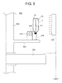
Fig. 5 is a vertical sectional view showing a state in which a structure for performing static charge elimination of a resin vessel is provided for a rinser, which concerns a third embodiment of the present invention. - Hereunder, the present invention will be described with reference to preferred embodiments represented by the accompanying drawings.
-
Fig. 1 shows a sterilizing and filling apparatus (entirely denoted by reference numeral "1" for a resin vessel in which liquid is filled as an inner content and is then capped to seal the resin vessel after the sterilization. - With reference to
Fig. 1 , a left side represents a sterilizing zone S and a right side represents a filling and capping zone F, which may be merely called "filling zone" for the sake of convenience. In the sterilizing zone S, there is provided asterilization chamber 6 surrounded by a wall structure 4 made of lead for shielding electron beam or X-ray (braking X-ray) from leaking outside at a time when aresin vessel 2 is irradiated with the electron beam to sterilize thevessel 2. - Within this
sterilization chamber 6, there are provided an inlet side carry-inchamber section 10, amain chamber section 14, anirradiation chamber section 20 and a carry-out chamber section 22. - In the carry-in
chamber section 10, a carry-inwheel 8 is disposed, and in themain chamber section 14, there is disposed aconveyance wheel 12 which rotates and conveys theresin vessel 2 transferred from the carry-inwheel 8. Theirradiation chamber section 20 is disposed on the front side of anelectron beam irradiator 16, and in thisirradiation chamber section 20, theresin vessel 2 is conveyed in a state of being held by a bottle support unit 18 (seeFig. 2 ) mounted to the carry-inwheel 12. The carry-outchamber section 22 is formed continuously to an outlet side (right side inFig. 1 ) of theirradiation chamber section 20 and adapted to convey theresin vessel 2, which was sterilized by the electron beam irradiation, to the downstream side (i.e. , filling zone F) of a vessel conveyance path or route while maintaining aseptic condition of the sterilizedvessel 2. Thesechamber sections plates sterilization chamber 6. Furthermore, these wall sections 4 and thepartition walls resin vessel 2 to pass through for transferring of theresin vessel 2, respectively. - The
vessel 2 which is sterilized in the sterilizing zone S and filled up with an inner content such as liquid in the downstream-side filling zone F is made of resin such as PET bottle has a shank (body) portion substantially rectangular in cross section (as schematically shown inFig. 1 ) and has an uppercylindrical mouth portion 2a as shown inFig. 2A . Furthermore, aflange portion 2b is formed to a lower side of thecylindrical mouth portion 2a, and theresin vessel 2 is conveyed in a suspended state such that a portion above or below theflange portion 2b is held by a gripper or a lower surface side of theflange portion 2b is held by abottle support unit 18 or other support unit or member. - The
resin vessel 2 is continuously conveyed by anair conveyer 29 and separated one by one at a predetermined interval by an infeed screw, not shown, and thereafter, therespective resin vessel 2 is carried in inside the carry-inchamber section 10 disposed on the inlet side of thesterilization chamber 6. - The carry-in
wheel 8 disposed within the carry-inchamber section 10 is provided with a plurality ofgrippers 30 arranged at an equal interval in a circumferential direction thereof, and eachgripper 30 grips a portion above theflange portion 2b of theresin vessel 2 and conveys theresin vessel 2 in the gripped state. Theresin vessel 2 held by thegrippers 30 of the carry-inwheel 8 and conveyed while being rotated are transferred to theconveyance wheel 12 arranged inside themain chamber section 14. - A plurality of
bottle support units 18 are mounted to theconveyance wheel 12 arranged inside themain chamber section 14 at an equal interval in the circumferential direction thereof (seeFig. 2A ), and each of thesebottle support units 18 supports the lower surface side of theflange portion 2b of eachresin vessel 2 and convey theresin vessel 2 in this state. - The carry-in
wheel 8 and theconveyance wheel 12 are rotated synchronously, and each of theresin vessels 2 is transferred to each of thebottle support units 18 at the vessel transferring position "A" from thegripper 30 of the carry-inwheel 8. - The
resin vessels 2 are rotated and conveyed in the state supported by the respectivebottle support units 18 of theconveyance wheel 12. Continuously, theresin vessels 2 pass inside theirradiation chamber section 20, and during the passing through theirradiation chamber section 20, theresin vessel 2 is irradiated along the vertically entire longitudinal direction with the electron beam emitted from theelectron beam irradiator 16, thereby being sterilized. Thus the sterilizedresin vessel 2 is guided into the carry-outchamber section 22 continuously arranged to theirradiation chamber section 20 and then transferred to the carry-outwheel 34. - The carry-out
wheel 34 is provided with a plurality ofgrippers 36 on the peripheral portion thereof at an equal interval in the circumferential direction, and each of thegrippers 36 receives each of theresin vessels 2 supported by each of thebottle support units 18 of theconveyance wheel 12 by gripping and holding the portion above theflange portion 2b of theresin vessel 2. This carry-outwheel 34 is also synchronously rotated with theconveyance wheel 12, and at the transferring position "B", theresin vessel 2 is transferred to eachgripper 36 of the carry-outwheel 34 from thebottle support unit 18 of theconveyance wheel 12. - The
resin vessel 2 held by thegripper 36 of the carry-outwheel 34 is then transferred to a vessel support unit, not shown, of asupport wheel 39 arranged on an inlet side of a succeeding chamber (i.e.,chamber 37 in the filling zone F) to be thereby subjected to a next process. - The
sterilization chamber 6 has anopening 4a formed to the lead wall section (structure) 4 at the portion where theirradiation chamber section 20 is formed, and theelectron beam irradiator 16 is mounted to thisopening 4a. Thiselectron beam irradiator 16 is provided with a vacuum chamber (acceleration chamber), not shown, for irradiating theresin vessel 2 with the electron beam, and as is known, a filament is heated in an evacuated atmosphere in the vacuum chamber to thereby generate thermal electrons, which are then accelerated by applying a high voltage to create high speed of electron beam. Thereafter, the electron beam is taken out into atmosphere through a metal foil such as titanium(Ti) attached to anirradiation window 16a of theelectron beam irradiator 16, and the taken-out electron beam is thereafter struck onto an object to be treated (herein, resin vessel 2) to perform the sterilization thereof. Further, though not shown inFig. 1 , a beam collector 38 (as shown inFig. 2A ) is disposed on a back side of theresin vessel 2 irradiated with the electron beam generated from theelectron beam irradiator 16. - Hereunder, with reference to
Figs. 2A and 2B , the structures of each of thebottle support units 18 provided for theconveyance wheel 12 and an earth electrode to be inserted into theresin vessel 2 at the sterilization process will be briefly described. - The
conveyance wheel 12 is provided with aplate 40 having a horizontal disc-shape, an annularrotary plate 41 fixed to the outer periphery of the disc-shapedplate 40, and an annularintermediate plate 42 disposed above therotary plate 41 to be integrally rotatable therewith. A plurality of cylindricalrotating shafts 44 extending perpendicularly are supported to be rotatable to outer peripheral portions of therotary plate 41 and theintermediate plate 42 throughball bearings - A
horizontal mount member 50 is fixed to the lower end portion of these cylindricalrotating shafts 44. A pair ofgrip members Fig. 2A ) are provided on the lower side of themount member 50 so as to hold theresin vessel 2 at the directly lower positions of the cylindricalrotating shafts 44, respectively. - Further, the
bottle support unit 18 has a structure substantially the same as abottle support unit 18 disclosed in the Japanese Patent Application No.2008-280304 grip members resin vessel 2 are held by the spring forces of these plate springs 54A and 54B. - A
pinion gear 64 is fixed to an upper (top) end portion of each of the cylindricalrotating shafts 44, to which thebottle support unit 18 is mounted, to be projected above theintermediate plate 42. Furthermore, the cylindricalrotating shaft 44 is supported by both of the annularrotary plate 41 and the annularintermediate plate 42 respectively fixed to the outer periphery of the disc-shapedplate 40. Anintermediate shaft 66 extending vertically is rotatably supported byball bearings plates cylindrical shaft 44. - Further,
sector gear 72 is mounted to the upper end portions of the respectiveintermediate shafts 66 at substantially the same height level as that of thepinion gear 64 of therotating shafts 44, respectively. Teeth are formed to radially outward surface portion of theconveyance wheel 12, the teeth being meshed with the pinion gears 64. - On the other hand, a
vertical pin 74 is attached to the end portion of thesector gear 72 directed radially inward of theconveyance wheel 12, that is, left side end inFig. 2A , and acam follower 76 is supported to the upper end portion of thevertical pin 74 to be rotatably. - Furthermore, a
tension coil spring 80 is interposed between the lower end portion of thevertical pin 74 and aspring receiving pin 78 fixed to an inner peripheral end of theintermediate plate 42 so as to attract the end portion of thesector gear 72 toward the radially inward direction of theconveyance wheel 12. - Above the disc-shaped
plate 40 of theconveyance wheel 12, there is disposed a circular fixedplate 82, which does not rotate or is not rotated, and arotational cam 84 for swinging thesector gear 72 is fixed to the outer peripheral portion of the fixedplate 82. The outer peripheral surface of thecam 84 is formed as a cam surface, along which thecam follower 76 is moved while being rotated. According to the swinging motion of thesector gear 72 in the radial direction in accordance with the rotating movement of thecam follower 76, thesector gear 72 is rotated around theintermediate shaft 66 to thereby rotate thepinion gear 64. - Each of the
bottle support units 18 is mounted to the lower end portion of the cylindricalrotating shaft 44, to the upper end of which thepinion gear 72 is fixed, and according to the swinging motion of thesector gear 72, thepinion gear 64 is rotated, and the cylindricalrotating shaft 44 disposed above the mouth portion of theresin vessel 2 is rotated, thereby rotating theresin vessel 2, now being conveyed in the state supported by thebottle support unit 18, around the central axis thereof. The above operations will be performed with respect to the respectivebottle support units 18 and their associated members or units. - According to the embodiment mentioned above, the pinion gears 64 are rotated by the pivotal motions of the
sector gear 72, and theresin vessel 2 is thereby rotated by about 180 degrees in the positive and reverse directions. - The
horizontal mount member 50 mentioned hereinbefore is formed with a throughhole 50a at a portion vertically according with aninner hole 44a of the cylindricalrotating shaft 44. A top surface and the outer peripheral surface of theconveyance wheel 12 are covered with acover 88. Thiscover 88 is composed of a metal material having conductivity. Furthermore, the upper portion of thepinion gear 64 reaches thecover 88 covering the top portion extending upward, and a space between it and thecover 88 is sealed to be swingable. According to such structure, thecircular hole 44a of therotating shaft 44 and thecircular hole 64a of thepinion gear 64 fixed to the upper end portion of therotating shaft 44 vertically penetrate the inner space defined by the disc-shapedplate 40 and thecover 88, so that an ambient environment maintained in the aseptic condition and an inner environment surrounded by the disc-shapedplate 40 and thecover 88 are shut off therebetween. - The
conveyance wheel 12 is provided with theearth electrode 90, which is inserted into theresin vessel 2 at the time of irradiating theresin vessel 2 with the electron beam. Theearth electrode 90 is attached to the lower end of asupport rod 92 standing vertically, and theseearth electrode 90 and thesupport rod 92 are disposed so as to be vertically movable through thecircular holes rotating shaft 44 and thepinion gear 64 and the throughhole 50a formed to thehorizontal mount member 50 disposed on the lower side thereof . - A mechanism for vertically moving each of the
earth electrodes 90 will be described hereunder with reference toFig. 2 . - The mechanism includes a vertically standing
guide mechanism 94 disposed above thecover 88 inward the position at which the cylindricalrotating shaft 44 is arranged. Thisguide mechanism 94 is provided with, as shown inFigs. 2A and 2B , anupright guide member 96 and aplurality guide rollers 98 attached to vertical plural portions of theguide member 96. Theguide rollers 98 are arranged at vertically appropriate portions of theguide member 96 respectively in pairs, and an elevatingrod 100 is disposed to be vertically movable in a state supported by theguide rollers 98 and theguide member 96. To the lower end portion of the elevatingrod 100, there are mounted thesupport rod 92 and theearth electrode 90 through ahorizontal mount member 102 so that theearth electrode 90 is vertically movable by the elevating motion of the elevatingrod 100. - Further, the
earth electrode 90 may be made of metal such as stainless, aluminum, titanium and the like, or other electrically conductive material. Furthermore, theearth electrode 90 may have various shapes, such as round-rod shape, having square, rectangular or polygonal section. Further, the outer peripheral surface of theearth electrode 90 may be formed with a plurality of projections so as to provide saw-teeth shape or may be provided with a brush to easily induce charges. - A horizontal
steady member 103 is disposed, independently from theconveyance wheel 12, above the top surface of thecover 88, and an elevatingcam 104 is attached to the outer peripheral portion of thesteady member 103. Furthermore, an elevating (liftable)member 106 is fixed to the elevatingrod 100 at a position higher than the location of themount member 102, and acam follower 108 is mounted to an end portion of the elevatingmember 106. Thiscam follower 108 moves while rotating on the upper surface (cam surface) of the elevatingcam 104 to be moved up and down in accordance with the cam shape of the elevatingcam 104 to thereby moving up and down theearth electrode 90. - When the
cam follower 108 is pushed upward by the elevatingcam 104 to the most upward position, the lower end of theearth electrode 90 takes a position above themouth portion 2a of theresin vessel 2, and on the contrary, when it is lowered to the most downward position, the lower end of theearth electrode 90 is inserted into theresin vessel 2 to a position near theinner bottom surface 2c thereof as shown inFig. 2A . - It is further to be noted that, at this operation, the lowering motion of the lower end of the elevating
rod 100 is restricted by abutment of thehorizontal mount member 102 against thesupport member 110 fixed to the top surface of thecover 88, and at this time, thecam follower 108 stops at a height level at which thecam follower 108 does not contact the cam surface of the elevatingcam 104. Under this state, theearth electrode 90 becomes conductive to thecover 88 which is made of metal conductive material through thesupport rod 92, themount member 102 and thesupport member 110, thus creating the conductive state between theearth electrode 90 and thecover 88 and flowing the electric charge from theearth electrode 90 to thecover 88. - After the
resin vessel 2 conveyed in a state of being supported by thebottle support unit 18 of theconveyance wheel 12 is irradiated with the electron beam emitted from theelectron beam irradiator 16 to sterilize theresin vessel 2, theresin vessel 2 is transferred to thegripper 36 of the carry-outwheel 34 and then rotated and conveyed outward. - The filling zone F includes a
chamber 37 arranged adjacent to thesterilization chamber 6 of the sterilizing zone S. Theresin vessel 2 rotated and conveyed by the carry-outwheel 34 of the sterilizing zone S is transferred to afiller 112 through thesupply wheel 39 arranged on an inlet (entrance) side of thechamber 37 in the filling zone F. - The
resin vessel 2 transferred to thesupply wheel 39 is conveyed, while being rotated, and is then transferred to thefiller 112. Thefiller 112 receiving theresin vessel 2 from thesupply wheel 39 fills theresin vessel 2 with the inner content such as liquid during the rotation and conveyance of theresin vessel 2. Theresin vessel 2 filled up with the inner content by thefiller 112 is taken out by anintermediate wheel 114 which also acts as a discharge wheel of thefiller 112 and a supply wheel of the capper and then supplied to thecapper 116. Theresin vessel 2 subjected to the capping operation by thecapper 116 is taken out fromcapper 116 by thedischarge wheel 118, and then fed for the next process by means of thedischarge conveyer 120. - The
filler 112 is provided, as shown inFig. 3 , with a rotary table 126 attached to arotating shaft 124 vertically extending at the central portion of the rotation, and the rotary table 126 has an outer periphery to which grippers 128 for holding theresin vessel 2 is arranged at an equal interval in the circumferential direction thereof. - Each of these
grippers 128 is attached to anupright stand 130 so as to be directed radially outward, and each of theresin vessels 2 is held by each of thegrippers 128 and then conveyed while being rotated. Further, fillingnozzles 132 are arranged above therespective resin vessels 2 held by thegrippers 128, respectively. Each of the fillingnozzles 132 is attached to an outer periphery of a second rotary table 133 arranged above the rotary table (first rotary table) 126, and theresin vessel 2 held by thegripper 128 and then conveyed, while being rotated, is then fed with a conductive liquid fed through aliquid supply pipe 135. The liquid fills theresin vessel 2 from each fillingnozzle 132 during the movement along a predetermined section (corresponding to a filling area from the position C to the position D inFig. 1 ) . - The
filler 112 is provided with a superimposed voltage-type (voltage-apply-type)ionizer 134, as static elimination device, outside the vessel conveying path or route by thegripper 128. This ionize 134 is disposed on the outer peripheral side of a rear side of the filling process near the filling finishing position D of thefiller 112, and as shown inFig. 3 , thisionizer 134 is positioned at a height level capable of emitting ions throughout the entire length of theresin vessel 2 and has a vertical length capable of achieving such ion emission. Further, since the structure of this voltage-applytype ionizer 134 is well known, detailed explanation thereof is omitted herein. That is, it has a structure in which corona discharge is spontaneously caused to a tapered sharp electrode needle by applying a high voltage, and in this embodiment, an ionizer generating only negative ions is adopted by applying a negative high voltage. - The filling
nozzle 132 is connected to anearth 138 side of theionizer 134 through therotating shaft 124 of thefiller 112 made of conductive metal and a base 136 supporting thisrotating shaft 124, and as mentioned hereinafter, an ion route or path connecting a space between the fillingnozzle 132 and theionizer 134 is formed. Further, in this embodiment, although the position at which theionizer 134 on the outer peripheral side of thefiller 112 is disposed is determined to the rear side position near the filling finishing position D in the filling section of thefiller 112, this position is not necessarily determined to this rear side position, and it may be disposed at a front half position thereof . However, it is necessary for theionizer 134 to be disposed in areas C-D in which the filling process is performed, and it is preferred to fill theresin vessel 2 with much liquid amount. - The operation and function of the sterilizing and filling
apparatus 1 of the structures mentioned above will be explained hereunder. - The
resin vessel 2 to be sterilized by the sterilizing and filling apparatus according to this embodiment are conveyed by theneck conveyer 29 and separated with a predetermined pitch interval and then carried into the carry-inchamber section 10 of theaseptic chamber 6 surrounded by the outer wall sections 4 made of lead. The carry-inwheel 8 disposed within the carry-inchamber section 10 is equipped with a plurality of thegrippers 30 arranged at an equal interval in the circumferential direction thereof, and thegrippers 30 grip the upper side portions of theflanges 2b formed to the lower side of thecylindrical mouth portions 2a of theresin vessels 2, respectively, carried into the carry-inchamber section 10 from the outside theaseptic chamber 6. - Each of the
resin vessels 2 held by thegripper 30 is rotated and conveyed by the rotation of the carry-inwheel 8, and transferred to thebottle support unit 18 provided for theconveyance wheel 12 from thegripper 30 of the carry-inwheel 8 at the bottle transferring position A. - Each of the
bottle support units 18 is rotated and moved in such a manner that one of thegripping members mouth portion 2a of theresin vessel 2 held by thegripper 30 of the carry-inwheel 8 is pushed into the space between thegripping members members mouth portion 2a of theresin vessel 2 is pushed into the space between both thegripping members Fig. 2A , the lower side of theflange 2b of theresin vessel 2 is held so that the lower surface thereof is supported as shown inFig. 2A . - According to the rotating motion of the
conveyance wheel 12, theresin vessel 2 supported by thebottle support unit 18 is rotated and conveyed in an arrowed direction R as shown inFig. 1 and enters the electron beamirradiation chamber section 20. - When the
resin vessel 2 is irradiated with the electron beam in theirradiation chamber section 20, theearth electrode 90 is lowered by the elevatingcam 104, and as shown inFig. 2A , is inserted into theresin vessel 2 so that the tip (lower) end portion thereof reaches a position of a height level near thebottom surface 2c of theresin vessel 2. Further, in the sections or areas other than the area in which the electron beam irradiates theresin vessel 2, theearth electrode 90 is raised upward by the elevatingcam 104 so that the tip end thereof is positioned above themouth portion 2a of theresin vessels 2. - As mentioned above, the
resin vessel 2 into which theearth electrode 90 is inserted is irradiated with the electron beam to be thereby sterilized during the movement in front of the irradiatingwindow 16a of theelectron beam irradiator 16. If the electron beam irradiates theresin vessel 2 with noearth electrode 90, theresin vessel 2 is charged, but as in this embodiment, by inserting theearth electrode 90 into theresin vessel 2 at the electron beam irradiation period, the emitted electron beam passes through the resin material forming theresin vessel 2, and the electrons entering inside theresin vessel 2 through the opening of themouth portion 2a are introduced by theearth electrode 90 and flow into the entire structure of the apparatus from thecover 88 through thesupport rod 92, themount member 102 and thesupport member 110, thus suppressing the interior of the resin material forming the inner surface and the wall section of theresin vessel 2 from being charged. Especially, the electrons emitted from theelectron beam irradiator 16 towards the outer surface of theresin vessel 2 act to transmit the resin material by not only the penetrating force by the acceleration at the time of electron beam irradiation but also the induction to theearth electrode 90 from the interior of theresin vessel 2, and hence, the electrons remain the interior of the resin material, thus being suppressed from being charged. - Further, the cylindrical
rotating shaft 44 to which each of thebottle support units 18 is mounted, and thepinion gear 64 fixed to the upper end thereof is meshed with thesector gear 72, which is swung by therotational cam 84 mounted to the outer periphery of the fixingplate 82 disposed above thesector gear 72. During the movement in front of theelectron beam irradiator 16 by the operation of therotational cam 84, the cylindricalrotating shaft 44 is rotated so that theresin vessel 2 supported by thebottle support unit 18 is rotated by about 180 degrees in positive and reverse directions. - As mentioned above, by the rotation of the
resin vessel 2 by about 180 degrees in front of the electronbeam irradiating window 16a of theelectron beam irradiator 16, the inner and outer surfaces of theresin vessel 2 can be irradiated with the electron beam throughout the entire longitudinal (vertical) direction thereof, thereby being sterilized. - The
resin vessel 2, which is irradiated with the electron beam and hence sterilized during the passing through the interior of the irradiatingchamber section 20 , is rotated and conveyed while being supported by thebottle support unit 18 and then conveyed into the adjacent carry-outchamber section 22 from theirradiation chamber section 20. Within the carry-outchamber section 22, the carry-outwheel 34 is disposed, and theresin vessel 2, in which the lower side portion of theflange 2b is supported by thebottle support unit 18, is transferred to thegripper 36 of the carry-outwheel 34 at the transferring position B and the upper side portion of theflange 2b is then gripped. Theresin vessel 2 rotated and conveyed while being held by thegripper 36 of the carry-outwheel 34 is then transferred to thesupply wheel 39 disposed on the inlet side of the subsequent chamber (i.e.,chamber 37 in the filling zone F). - The
resin vessel 2 rotated and conveyed while being held by a vessel holding unit, not shown, of thesupport wheel 39 is supplied to thefiller 112 and then held by thegripper 128. The fillingnozzle 132 is then inserted into theresin vessel 2 and starts the filling operation at the predetermined position (filling starting position C). The filling operation is continued during the rotation and movement in the filling areas C-D, and as the filled amount increases, and in the rear side period in the filling areas C-D, theresin vessel 2 reaches to the position at which the voltage-applytype ionizer 134 is disposed outside the resin vessel conveying path, and at this position, theresin vessel 2 is emitted with the ions from theionizer 134. In the present embodiment, when theelectron beam irradiator 16 irradiates theresin vessel 2 with the electron beam, theearth electrode 90 is inserted, and in addition, by the emission of the ion from theionizer 134, the charges remaining inside the wall section of theresin vessel 2 can be eliminated. - In this embodiment, since the electrons, i.e., negative charges, remain in the interior of the wall section of the
resin vessel 2 by the sterilization due to the electron beam irradiation in the sterilizing zone S, theionizer 134 emits, with the negative charges of the same polarity, the outer surface of theresin vessel 2. If the negative charges remain in the interior of the wall section of theresin vessel 2, there creates a state in which the positive charges are on the outer surface and inner surface (inside wall section of the resin vessel 2) of theresin vessel 2. Under this state, if the negative ion emission is performed from the outer surface side of theresin vessel 2, the positively charged ions on the outer surface of theresin vessel 2 is neutralized, and then, the negatively charged ions float on the outer surface side thereof. As a result, a large amount of negative charges exists on the outer surface side of theresin vessel 2 and the interior of the wall section thereof. - Furthermore, an ion path or route connecting the
ionize 134 and the fillingnozzle 132 is formed via the filling liquid L filling theresin vessel 2 and the liquid column La flowing downward from the fillingnozzle 132, so that the ions having positive charges in the filling liquid L are attracted to the inner surface side of theresin vessel 2 and, on the other hand, the ions having negative charges in the filling liquid L flow to theionizer 134 side via the liquid column La in the liquid flow and the fillingnozzle 132, thus existing a large amount of ions having positive charges in the filling liquid L. - According to the processes mentioned above, at a time when the negative ion emission from the
ionizer 134 has finished, a large amount of ions having negative charges exists on the outer surface side of theresin vessel 2, and the ions also having negative charges exists in the interior of the wall section thereof. According to such existence of the negatively charged ions, the ions having positive charges in the filling liquid L are attracted to inner surface side of theresin vessel 2, and hence, the negative charges remaining in the interior of the wall section of theresin vessel 2 are neutralized. - Furthermore, the ion neutralization reaction is more easily achieved in an atmosphere including much water content than in a dried condition, and as time elapses thereafter, the ions having positive charges in the filling liquid L and the negative charges remaining inside the wall section of the
resin vessel 2 are mutually attracted to each other, thereby being neutralized. - As mentioned above, by generating, in the filling liquid to fill the interior of the
resin vessel 2, a large amount of ions carrying positive charges which have a polarity reverse to that of the negative charges remaining in the interior of the wall section of theresin vessel 2, the neutralization reaction is more promoted in water than in atmosphere, and by utilizing this nature, the static elimination can be more effectively performed in the water than performed in the atmosphere by the ion emission. Moreover, since a large amount of ions having positive charges exists in the filling liquid L, the reaction continues even after the emission by the ionizer, and hence, the negative charges remaining in the interior of the wall section of theresin vessel 2 can be largely eliminated. - Further, in this embodiment, although the filling
nozzle 132 is connected to theearth 138 on theionize side 134 to thereby flow the negative ions on theionizer side 134, it is not always necessary to be connected to theionizer side 134, and the fillingnozzle 132 may be earthed independently from theionizer 134. - Furthermore, in the above-described embodiment, although the voltage-applied type ionize 134 is arranged on the outer peripheral side of the vessel conveying path by the
filler 112, it is not always necessary to perform the ion emission during the filling process by thefiller 112, and the ionizer may be disposed so as to perform the ion emission at the other portions. That is, in a second embodiment, anionizer 234 is arranged outside of the vessel conveying path formed by theintermediate wheel 114 acting commonly as the discharge wheel from thefiller 112 and a supply wheel to thecapper 116. - On the other hand, an electrode rod (earth electrode recited in claim 3) 140 to be inserted into the filling liquid L filled into the
resin vessel 2 is provided for theintermediate wheel 114, as shown inFig. 4 , which supplies theresin vessel 2 taken out from thefiller 112 to thecapper 116. - The
intermediate wheel 114 includes afirst rotary wheel 114 around the outer peripheral portion of a vertically standing rotating shaft 142, being the center of rotation of therotary wheel 144, and a plurality ofgrippers 146 holding theresin vessels 2, respectively, are disposed to the outer peripheral portion of thefirst rotary wheel 144 at an equal interval in the circumferential direction thereof. - Furthermore, a
second rotary wheel 148 is located above thefirst rotary wheel 144 , and a plurality ofelectrode rods 140 are provided in a manner such that eachelectrode rod 140 corresponds to each of theresin vessels 2, in the vertical alignment, held by thegripper 146. Eachelectrode rod 140 is fixed in a manner directed vertically downward, through ahorizontal mount plate 152, to an elevatingcylinder 150 fixed to thesecond rotary wheel 148 in a manner directed upward so as to be moved up and down in accordance with the actuation of the elevatingcylinder 150. - The
electrode rod 140 is operatively connected to theionizer 234 side via thehorizontal mount plate 152, the elevatingcylinder 150, the secondrotary plate 148, the upright rotating shaft 142, a fixingbase 154 and so on, which are all made of conductive metal materials, whereby when theelectrode rod 140 is inserted into the filling liquid L filled in theresin vessel 2, the ion flow path is formed from theelectrode rod 140 to theionizer 234 through the filling liquid L. - According to the structure of the second embodiment mentioned above, the voltage-applied
type ionizer 234 emits to the outer peripheral surface of theresin vessel 2 with the negative ions in the state that theelectrode rod 140 is lowered to be inserted into the filling liquid L by the operation of the elevatingcylinder 150. In the interior of the wall section of theresin vessel 2, the negative charges remain, and there are positively charged ions on the outer and inner surfaces thereof. Accordingly, the emission of the negative ions from theionizer 234 from the outer surface side of theresin vessel 2 neutralizes the ions having the positive charges adhering on the outer surface side thereof. Furthermore, the ions having the positive charges in the filling liquid L are attracted to the inner surface side of theresin vessel 2, and the negative ions in the filling liquid L flows outward through a circuit from theelectrode rod 140 to theionizer 234. Thus, according to this embodiment, the sterilization of theresin vessel 2 is performed by the electron beam irradiation, so that the negative charges remaining in the interior of the wall section of theresin vessel 2 can be largely eliminated. - In the respective embodiments described above, the voltage-applied
type ionizers filler 112 or outside of the discharge wheel (intermediate wheel 114) from thefiller 112, and the outer surface of theresin vessel 2 which is filled with the liquid L is emitted with the negative ions to thereby neutralize the negative charges remaining inside the wall section of theresin vessel 2. However, it is not always necessary to emit to theresin vessel 2 which is filled with the liquid L with the ions, and for example, the ion emission may be performed from the outside of the resin vessel to which cleaning liquid is blown by a rinser, and in such case, the charge remaining inside the wall section will be likely eliminated. -
Fig. 5 represents a third embodiment in which a voltage-appliedtype ionizer 334 is disposed outside arinser 300. Therinser 300 of this embodiment is equipped with a plurality of cleaningnozzles 306 to the outer peripheral portion of therotary wheel 304 mounted to the outer peripheral surface of the centralrotating shaft 302 at an equal interval in the circumferential direction of therotary wheel 304. -
Bottle grippers 308 are arranged at portions radially inward of the cleaningnozzles 306, respectively. Thesebottle grippers 308 are pivotal around horizontally arranged fulcrum pins 310, respectively, to be reciprocally movable between a position (i.e., position shown inFig. 5 ) at which the mouth portion of theresin vessel 2 held in an inverted attitude faces a drain port of thecleaning nozzle 306 and a position offset from the cleaningnozzle 306. Each of the cleaningnozzles 306 is earthed by being connected to the voltage-appliedtype ionizer 334 side via conductive metal members such as therotary wheel 304, the uprightrotating shaft 302, to which therotary wheel 304 is mounted, and the base 312 supporting the rotating shaft to be rotatable. - In this embodiment, although the liquid L does not fill the
resin vessel 2 as in the former embodiments, the outer surface of theresin vessel 2 is emitted with the negative ions from theionizer 334 during the cleaning process in which the cleaning liquid is jetted toward the inner sidebottom surface 2c of theresin vessel 2 from the cleaningnozzle 306, thereby achieving substantially the same effects and functions as those attained by the former embodiments. - During the cleaning process in which the cleaning liquid is jetted from the cleaning
nozzle 306, the cleaning liquid jetted from the cleaningnozzle 306 to thebottom surface 2c of theresin vessel 2 flows downward along the inside surface of theresin vessel 2. In this state, if the ion emission is performed, the cleaningnozzle 306 and theionizer 334 become conductive through the liquid column Lc blowing to thebottom surface 2c of theresin vessel 2, and hence, the positively charged ions flaw to the earth side of theionize 334 via thecleaning nozzle 306, therotary wheel 304, therotating shaft 302 and thebase 312, as mentioned above, and the positively charged ions existing in the cleaning liquid Lb are attracted to the inner surface side of theresin vessel 2. - As mentioned above, even in the case where the
resin vessel 2 is not filled with the liquid, the cleaningnozzle 306 can be earthed, while performing the rinsing process, through the liquid column Lc of the cleaning liquid jetted from the cleaningnozzle 306 and the cleaning liquid Lb flowing along the inner surface of theresin vessel 2, thereby attaining substantially the same effects as those attained by the former embodiment.
Claims (16)
- A method of eliminating static charge from a resin vessel by using an apparatus including a liquid supply unit for supplying a liquid into a resin vessel and a charge applying unit for applying charge to an outer surface of the resin vessel, wherein, by applying charge having a same polarity as that of charge remaining in an interior of a wall section of the resin vessel, while supplying the liquid into the resin vessel, ion carrying charge having a polarity reverse to that of the charge remaining in an interior of the wall section of the resin vessel is attracted to an inner surface of the resin vessel.
- The method of eliminating static charge from a resin vessel according to claim 1, wherein the charge applying unit is a device for emitting to the outer surface of the resin vessel with ions.
- A method of sterilizing and filling a resin vessel including a sterilizing process for sterilizing a resin vessel by being irradiated with electron beam and a filling process for filling the resin vessel with a liquid, wherein a filling nozzle for filling the resin vessel with the liquid and a negative charge applying unit for applying negative charge on an outer surface of the resin vessel are provided, and during the liquid filling process into the resin vessel, the negative charge is applied to the outer surface of the resin vessel.
- The method of sterilizing and filling a resin vessel according to claim 3, wherein the negative charge applying unit is a device for emitting to the outer surface of the resin vessel with ions.
- A resin vessel filling and capping method including a sterilizing process for sterilizing a resin vessel by being irradiated with electron beam, a filling process for filling a liquid into the resin vessel and a capping process for applying a cap to the resin vessel after completion of the liquid filling, wherein a conductive member to be inserted into the resin vessel and a negative charge applying unit for applying negative charge onto an outer surface of the resin vessel are provided, and during a period between the filling process and the capping process, the conductive member is contacted to the liquid filled into the resin vessel and the negative charge is applied to the outer surface of the resin vessel by the negative charge applying unit, and after the negative charge application, a cap is applied to the resin vessel.
- The resin vessel filling and capping method according to claim 5, wherein the negative charge applying unit is a device for emitting to the outer surface of the resin vessel with ions.
- A resin vessel filling and capping method including a sterilizing process for sterilizing a resin vessel by being irradiated with electron beam, a filling process for filling a liquid into the resin vessel and a capping process for applying a cap to the resin vessel after completion of the liquid filling, wherein a conductive member to be inserted into the resin vessel and a negative charge applying unit for applying negative charge onto an outer surface of the resin vessel are provided, and during a period between the filling process and the capping process, the negative charge is applied to the outer surface of the resin vessel by the negative charge applying unit to apply the negative charge, the conductive member is contacted to the liquid filled into the resin vessel after the application of the negative charge, and a cap is thereafter applied to the resin vessel.
- The resin vessel filling and capping method according to claim 7, wherein the negative charge applying unit is a device for emitting to the outer surface of the resin vessel with ions .
- An apparatus for eliminating static charge from a resin vessel comprising a liquid supply unit for supplying a liquid into a resin vessel and a charge applying unit far applying charge to an outer surface of the resin vessel which is filled with the liquid by the liquid supply unit, wherein charge having a same polarity as that of charge remaining in an interior of a wall section of the resin vessel is applied to the outer surface of the resin vessel by the charge applying unit during the supply of the liquid into the resin vessel by the liquid supply unit.
- The apparatus for eliminating static charge from a resin vessel according to claim 9, wherein the charge applying unit is a device for emitting to the outer surface of the resin vessel with ions.
- A resin vessel sterilizing and filling system, comprising:an electron beam irradiator for irradiating a resin vessel, which is being conveyed, with electron beam and sterilizing the resin vessel; a filling unit having a filling nozzle through which a liquid is discharged into the resin vessel from an upper portion of a mouth portion of the resin vessel irradiated with the electron beam; a capping unit for applying a cap to the resin vessel which is filled up with the liquid; and a negative charge applying unit for applying negative charge onto an outer surface of the resin vessel which is filled up with the liquid by the filling unit,wherein during the liquid filling process into the resin vessel by the filling unit, negative charge is applied to the outer surface of the resin vessel by the negative charge applying unit, and thereafter, a capping process is performed by the capping unit.
- The resin vessel sterilizing and filling system according to claim 11, wherein the negative charge applying unit is a device for emitting to the outer surface of the resin vessel with ions.
- A resin vessel sterilizing and filling system comprising:an electron beam irradiator for irradiating a resin vessel, which is being conveyed, with electron beam and sterilizing the resin vessel; a filling unit for filling the resin vessel, irradiated with the electron beam, with a liquid; a capping unit for applying a cap to the resin vessel which is filled up with the liquid; a conductive member inserting unit provided for a conveyance path between the filling unit and the capping unit and adapted for inserting a conductive member into the resin vessel; and a negative charge applying unit for applying negative charge onto an outer surface of the resin vessel which is filled up with the liquid by the filling unit,wherein a capping process is performed by the capping unit after the negative charge is applied by the negative charge applying unit to the outer surface of the resin vessel while contacting the conductive member to the liquid filled into the resin vessel between the filling unit and the capping unit.
- The resin vessel sterilizing and filling system according to claim 13, wherein the negative charge applying unit is a device for emitting to the outer surface of the resin vessel with ions.
- A resin vessel sterilizing and filling system comprising:an electron beam irradiator for irradiating a resin vessel, which is being conveyed, with electron beam and sterilizing the resin vessel; a filling unit for filling the resin vessel, irradiated with the electron beam, with a liquid; a capping unit for applying a cap to the resin vessel, filled up with the liquid; a conductive member inserting unit provided for a conveyance path between the filling unit and the capping unit and adapted for inserting a conductive member into the resin vessel; and a negative charge applying unit for applying negative charge onto an outer surface of the resin vessel into which the conductive member is inserted,wherein a capping process is performed by the capping unit after the negative charge is applied by the negative charge applying unit to the outer surface of the resin vessel while contacting the conductive member to the liquid filled into the resin vessel between the filling unit and the capping unit.
- The resin vessel sterilizing and filling system according to claim 15, wherein the negative charge applying unit is a device for emitting to the outer surface of the resin vessel with ions.
Applications Claiming Priority (1)
| Application Number | Priority Date | Filing Date | Title |
|---|---|---|---|
| JP2009156096A JP5336949B2 (en) | 2009-06-30 | 2009-06-30 | Resin container charge removal method, resin container sterilization filling method, resin container filling capping method, resin container charge removal device and resin container sterilization filling system |
Publications (4)
| Publication Number | Publication Date |
|---|---|
| EP2269943A2 true EP2269943A2 (en) | 2011-01-05 |
| EP2269943A3 EP2269943A3 (en) | 2013-11-20 |
| EP2269943B1 EP2269943B1 (en) | 2016-04-20 |
| EP2269943B8 EP2269943B8 (en) | 2016-08-10 |
Family
ID=42869122
Family Applications (1)
| Application Number | Title | Priority Date | Filing Date |
|---|---|---|---|
| EP10167477.8A Active EP2269943B8 (en) | 2009-06-30 | 2010-06-28 | Method and system for sterilizing and filling resin vessels |
Country Status (5)
| Country | Link |
|---|---|
| US (2) | US8505269B2 (en) |
| EP (1) | EP2269943B8 (en) |
| JP (1) | JP5336949B2 (en) |
| KR (1) | KR101630650B1 (en) |
| CN (1) | CN101962090B (en) |
Cited By (3)
| Publication number | Priority date | Publication date | Assignee | Title |
|---|---|---|---|---|
| EP3076766A1 (en) * | 2015-03-31 | 2016-10-05 | F. Hoffmann-La Roche AG | Method and apparatus for electrostatically discharging a primary packaging container made of plastics |
| WO2018037063A1 (en) * | 2016-08-26 | 2018-03-01 | Krones Ag | Filling system for filling a container with a filling product |
| EP4201433A1 (en) * | 2021-12-23 | 2023-06-28 | Krones AG | Device and method for treating and in particular sterilising containers |
Families Citing this family (14)
| Publication number | Priority date | Publication date | Assignee | Title |
|---|---|---|---|---|
| JP5336949B2 (en) * | 2009-06-30 | 2013-11-06 | サントリーホールディングス株式会社 | Resin container charge removal method, resin container sterilization filling method, resin container filling capping method, resin container charge removal device and resin container sterilization filling system |
| JP5660963B2 (en) * | 2011-04-12 | 2015-01-28 | 三菱重工食品包装機械株式会社 | Static eliminator |
| JP5752476B2 (en) * | 2011-04-20 | 2015-07-22 | 三菱重工食品包装機械株式会社 | Static eliminator, static elimination electrode |
| JP5848037B2 (en) * | 2011-06-15 | 2016-01-27 | 三菱重工食品包装機械株式会社 | Electron beam sterilizer |
| DE102011107772A1 (en) * | 2011-07-15 | 2013-01-17 | Krones Aktiengesellschaft | Method and device for producing beverage containers filled with liquids |
| JP5791459B2 (en) * | 2011-10-17 | 2015-10-07 | 日立造船株式会社 | Shielding structure for electron beam sterilization equipment |
| ITBO20110691A1 (en) | 2011-12-02 | 2013-06-03 | Ativa | LINE AND PROCESS OF BOTTLING IN CONTINUOUS CYCLE OF CONTAINERS IN THERMOPLASTIC MATERIAL. |
| JP5970856B2 (en) * | 2012-02-28 | 2016-08-17 | 澁谷工業株式会社 | Electron beam irradiation device |
| FR2991311B1 (en) * | 2012-05-31 | 2014-07-04 | Noviloire | DRILLING SYSTEM OF A OPERATOR |
| JP5783971B2 (en) * | 2012-08-10 | 2015-09-24 | 株式会社東芝 | Coating apparatus and coating method |
| EP3118129B1 (en) * | 2014-03-14 | 2021-05-19 | Dai Nippon Printing Co., Ltd. | Method and apparatus for the sterilisation of containers |
| CN104528059A (en) * | 2014-11-26 | 2015-04-22 | 界首市天鸿包装材料有限公司 | Dust preventing method for packing process |
| CN110921599B (en) * | 2019-12-13 | 2021-05-25 | 嵊州市雾非雾机械设备商行 | Liquid split charging equipment |
| CN112423459A (en) * | 2020-12-14 | 2021-02-26 | 江苏新美星包装机械股份有限公司 | Method and device for removing static electricity of resin container |
Citations (3)
| Publication number | Priority date | Publication date | Assignee | Title |
|---|---|---|---|---|
| JP2006216453A (en) | 2005-02-04 | 2006-08-17 | Techno Ryowa Ltd | Static eliminator of charged object and its method |
| JP2008280304A (en) | 2007-05-11 | 2008-11-20 | Daikin Ind Ltd | Method for producing fluorocarboxylic acid |
| JP2009051517A (en) | 2007-08-24 | 2009-03-12 | Kao Corp | Method for manufacturing container with content therein |
Family Cites Families (37)
| Publication number | Priority date | Publication date | Assignee | Title |
|---|---|---|---|---|
| US3768227A (en) * | 1970-09-16 | 1973-10-30 | R Grisell | Method of dissipating static electricity in packaging |
| US4180105A (en) * | 1978-10-27 | 1979-12-25 | Diamond International Corporation | Article inflating system |
| US4333123A (en) * | 1980-03-31 | 1982-06-01 | Consan Pacific Incorporated | Antistatic equipment employing positive and negative ion sources |
| US4415085A (en) * | 1981-12-21 | 1983-11-15 | Eli Lilly And Company | Dry pharmaceutical system |
| US4707414A (en) * | 1984-04-09 | 1987-11-17 | General Dynamics, Pomona Division | Electrostatic-free package |
| US4991379A (en) * | 1989-04-21 | 1991-02-12 | Zip-Pak Incorporated | Substantially frictionless and static-free former and feed tube |
| US5014849A (en) * | 1990-02-05 | 1991-05-14 | Conductive Containers, Inc. | Electro-static protective container for electrical components |
| US5199246A (en) * | 1992-09-08 | 1993-04-06 | Illinois Tool Works Inc. | Electrostatic method and apparatus for opening liners within containers |
| US5647193A (en) * | 1995-03-13 | 1997-07-15 | Southpac Trust International, Inc. | Pot wrapping apparatus and method |
| US5671591A (en) * | 1995-05-01 | 1997-09-30 | Ashland, Inc. | Integrated container moulding and filling facility |
| IT1285616B1 (en) * | 1996-03-15 | 1998-06-18 | Gd Spa | METHOD FOR WRAPPING A PRODUCT |
| IT1285619B1 (en) * | 1996-03-15 | 1998-06-18 | Co Me Sca Costruzioni Meccanic | BENDING METHOD OF A DIELECTRIC SHEET IN THE SHEET |
| JPH11214191A (en) * | 1998-01-30 | 1999-08-06 | Kazuo Okano | Glass substrate electricity removing device |
| JP4246819B2 (en) * | 1998-08-18 | 2009-04-02 | 浜松ホトニクス株式会社 | Static electricity removing method and apparatus |
| JP4330694B2 (en) * | 1999-04-23 | 2009-09-16 | アサヒ飲料株式会社 | Container cleaning device and container cleaning method |
| JP2002173114A (en) * | 2000-12-07 | 2002-06-18 | Ishikawajima Harima Heavy Ind Co Ltd | Method for sterilizing vessel |
| WO2002100762A2 (en) * | 2001-06-13 | 2002-12-19 | Ribi Pack Spa | Processes and devices for sealing containers with an extensible film |
| JP2003066198A (en) * | 2001-08-24 | 2003-03-05 | Mitsubishi Heavy Ind Ltd | Cap sterilizer and sterilizing method |
| JP4590805B2 (en) * | 2001-08-28 | 2010-12-01 | 凸版印刷株式会社 | Aseptic filling method for pouch with spout |
| JP3995535B2 (en) * | 2002-06-07 | 2007-10-24 | 株式会社コガネイ | Static eliminator |
| DE10254762A1 (en) * | 2002-11-22 | 2004-06-09 | Transcoject Gesellschaft für medizinische Geräte mbH & Co. KG | Process for producing and / or handling a high-purity object |
| ITMO20040111A1 (en) * | 2004-05-07 | 2004-08-07 | Sig Simonazzi Spa | APPARATUS AND METHODS FOR STERILIZING AND FILLING COMPONENTS OF PACKAGING UNITS, PARTICULARLY E-OR BOTTLES. |
| JP2006007012A (en) * | 2004-06-22 | 2006-01-12 | Koganei Corp | Charge removal/dedusting apparatus |
| SE528990C8 (en) * | 2005-08-23 | 2007-05-08 | Tetra Laval Holdings & Finance | Methods and apparatus for sterilizing packaging materials |
| JP2007106438A (en) * | 2005-10-13 | 2007-04-26 | Toyo Seikan Kaisha Ltd | Sterilizing method and sterilizing apparatus for package |
| JP4848173B2 (en) * | 2005-11-02 | 2011-12-28 | 三菱重工業株式会社 | Food container electron beam sterilization inspection system and food container electron beam sterilization inspection method |
| JP4910207B2 (en) * | 2005-11-25 | 2012-04-04 | Smc株式会社 | Ion balance adjustment method and work static elimination method using the same |
| JP4730190B2 (en) * | 2006-04-26 | 2011-07-20 | 澁谷工業株式会社 | Container sterilization apparatus and container sterilization method |
| WO2008046574A2 (en) * | 2006-10-18 | 2008-04-24 | Khs Ag | Method and device for treating plasstic containers |
| JP4940944B2 (en) * | 2006-12-28 | 2012-05-30 | 澁谷工業株式会社 | Container filling system |
| EP1982920A1 (en) * | 2007-04-19 | 2008-10-22 | Krones AG | Device for sterilising containers |
| CN101312613A (en) * | 2007-05-22 | 2008-11-26 | 鸿富锦精密工业(深圳)有限公司 | Destaticizer apparatus |
| US8132598B2 (en) * | 2007-07-11 | 2012-03-13 | Stokely-Van Camp, Inc. | Active sterilization zone for container filling |
| EP2119512B1 (en) * | 2008-05-14 | 2017-08-09 | Gerresheimer Glas GmbH | Method and device for removing contaminating particles from containers on automatic production system |
| US8293173B2 (en) * | 2009-04-30 | 2012-10-23 | Hitachi Zosen Corporation | Electron beam sterilization apparatus |
| JP5336949B2 (en) * | 2009-06-30 | 2013-11-06 | サントリーホールディングス株式会社 | Resin container charge removal method, resin container sterilization filling method, resin container filling capping method, resin container charge removal device and resin container sterilization filling system |
| DE102011012342A1 (en) * | 2011-02-24 | 2012-08-30 | Krones Aktiengesellschaft | Method and device for the sterilization of containers |
-
2009
- 2009-06-30 JP JP2009156096A patent/JP5336949B2/en active Active
-
2010
- 2010-06-23 US US12/803,276 patent/US8505269B2/en active Active
- 2010-06-25 KR KR1020100060687A patent/KR101630650B1/en active IP Right Grant
- 2010-06-28 EP EP10167477.8A patent/EP2269943B8/en active Active
- 2010-06-29 CN CN201010217995.9A patent/CN101962090B/en active Active
-
2013
- 2013-03-07 US US13/788,213 patent/US20130182363A1/en not_active Abandoned
Patent Citations (3)
| Publication number | Priority date | Publication date | Assignee | Title |
|---|---|---|---|---|
| JP2006216453A (en) | 2005-02-04 | 2006-08-17 | Techno Ryowa Ltd | Static eliminator of charged object and its method |
| JP2008280304A (en) | 2007-05-11 | 2008-11-20 | Daikin Ind Ltd | Method for producing fluorocarboxylic acid |
| JP2009051517A (en) | 2007-08-24 | 2009-03-12 | Kao Corp | Method for manufacturing container with content therein |
Cited By (6)
| Publication number | Priority date | Publication date | Assignee | Title |
|---|---|---|---|---|
| EP3076766A1 (en) * | 2015-03-31 | 2016-10-05 | F. Hoffmann-La Roche AG | Method and apparatus for electrostatically discharging a primary packaging container made of plastics |
| WO2016156229A1 (en) | 2015-03-31 | 2016-10-06 | F. Hoffmann-La Roche Ag | Method and apparatus for electrostatically discharging a primary packaging container made of plastics |
| US10548207B2 (en) | 2015-03-31 | 2020-01-28 | Hoffmann-La Roche Inc. | Method and apparatus for electrostatically discharging a primary packaging container made of plastics |
| WO2018037063A1 (en) * | 2016-08-26 | 2018-03-01 | Krones Ag | Filling system for filling a container with a filling product |
| US11078065B2 (en) | 2016-08-26 | 2021-08-03 | Krones Ag | Filling system for filling a container with a filling product |
| EP4201433A1 (en) * | 2021-12-23 | 2023-06-28 | Krones AG | Device and method for treating and in particular sterilising containers |
Also Published As
| Publication number | Publication date |
|---|---|
| EP2269943A3 (en) | 2013-11-20 |
| KR20110001919A (en) | 2011-01-06 |
| JP2011011775A (en) | 2011-01-20 |
| JP5336949B2 (en) | 2013-11-06 |
| CN101962090B (en) | 2014-03-12 |
| US20100326563A1 (en) | 2010-12-30 |
| US8505269B2 (en) | 2013-08-13 |
| CN101962090A (en) | 2011-02-02 |
| EP2269943B1 (en) | 2016-04-20 |
| US20130182363A1 (en) | 2013-07-18 |
| EP2269943B8 (en) | 2016-08-10 |
| KR101630650B1 (en) | 2016-06-15 |
Similar Documents
| Publication | Publication Date | Title |
|---|---|---|
| EP2269943B1 (en) | Method and device for sterilizing and filling resin vessels | |
| EP2213578B1 (en) | Apparatus and method for sterilizing vessel with electron beam | |
| JP2006518689A (en) | Apparatus and method for filling a container with a drug | |
| JP2007297067A (en) | Electron beam irradiation device for open container | |
| CN103209900B (en) | The surface modifying method of resin container and the surface modification device of resin container | |
| US9078935B2 (en) | Apparatus and method of sterilizing containers with a charge carrier source introduced into the containers | |
| JP6177827B2 (en) | Container cleaning device and beverage filling device | |
| JP5393612B2 (en) | Method and device for removing charge from resin container | |
| JP6577170B2 (en) | Container sterilization method and apparatus with cleaning of exit window | |
| JP5496842B2 (en) | Electron beam sterilization method and electron beam sterilizer | |
| US11370572B2 (en) | Surface treatment method and surface treatment device for resin vessel | |
| JP5818501B2 (en) | Static eliminator | |
| JP2012227092A (en) | Electricity removal apparatus | |
| JP6009038B2 (en) | Static eliminator | |
| JP2021095178A (en) | Electron beam sterilizer and method | |
| JP2012224371A (en) | Neutralizing apparatus and neutralizing electrode |
Legal Events
| Date | Code | Title | Description |
|---|---|---|---|
| PUAI | Public reference made under article 153(3) epc to a published international application that has entered the european phase |
Free format text: ORIGINAL CODE: 0009012 |
|
| AK | Designated contracting states |
Kind code of ref document: A2 Designated state(s): AL AT BE BG CH CY CZ DE DK EE ES FI FR GB GR HR HU IE IS IT LI LT LU LV MC MK MT NL NO PL PT RO SE SI SK SM TR |
|
| AX | Request for extension of the european patent |
Extension state: BA ME RS |
|
| PUAL | Search report despatched |
Free format text: ORIGINAL CODE: 0009013 |
|
| AK | Designated contracting states |
Kind code of ref document: A3 Designated state(s): AL AT BE BG CH CY CZ DE DK EE ES FI FR GB GR HR HU IE IS IT LI LT LU LV MC MK MT NL NO PL PT RO SE SI SK SM TR |
|
| AX | Request for extension of the european patent |
Extension state: BA ME RS |
|
| RIC1 | Information provided on ipc code assigned before grant |
Ipc: A61L 2/08 20060101ALI20131014BHEP Ipc: H05F 3/06 20060101ALI20131014BHEP Ipc: B67C 7/00 20060101AFI20131014BHEP |
|
| 17P | Request for examination filed |
Effective date: 20131206 |
|
| RBV | Designated contracting states (corrected) |
Designated state(s): AL AT BE BG CH CY CZ DE DK EE ES FI FR GB GR HR HU IE IS IT LI LT LU LV MC MK MT NL NO PL PT RO SE SI SK SM TR |
|
| 17Q | First examination report despatched |
Effective date: 20140930 |
|
| GRAP | Despatch of communication of intention to grant a patent |
Free format text: ORIGINAL CODE: EPIDOSNIGR1 |
|
| INTG | Intention to grant announced |
Effective date: 20151028 |
|
| RAP1 | Party data changed (applicant data changed or rights of an application transferred) |
Owner name: SHIBUYA KOGYO CO., LTD. |
|
| GRAS | Grant fee paid |
Free format text: ORIGINAL CODE: EPIDOSNIGR3 |
|
| GRAA | (expected) grant |
Free format text: ORIGINAL CODE: 0009210 |
|
| AK | Designated contracting states |
Kind code of ref document: B1 Designated state(s): AL AT BE BG CH CY CZ DE DK EE ES FI FR GB GR HR HU IE IS IT LI LT LU LV MC MK MT NL NO PL PT RO SE SI SK SM TR |
|
| REG | Reference to a national code |
Ref country code: GB Ref legal event code: FG4D |
|
| REG | Reference to a national code |
Ref country code: CH Ref legal event code: EP |
|
| REG | Reference to a national code |
Ref country code: AT Ref legal event code: REF Ref document number: 792229 Country of ref document: AT Kind code of ref document: T Effective date: 20160515 |
|
| REG | Reference to a national code |
Ref country code: IE Ref legal event code: FG4D |
|
| REG | Reference to a national code |
Ref country code: DE Ref legal event code: R096 Ref document number: 602010032399 Country of ref document: DE |
|
| REG | Reference to a national code |
Ref country code: FR Ref legal event code: PLFP Year of fee payment: 7 |
|
| RIN2 | Information on inventor provided after grant (corrected) |
Inventor name: NISHI, TOKUO Inventor name: YOKOI, TSUNEHIKO Inventor name: KOBAYASHI, TOSHIYA Inventor name: YAMAMOTO, YUKIHIRO Inventor name: NARITA, MITSUOMI Inventor name: ONISHI, TAKUYA Inventor name: HAYASHI, MASAMI Inventor name: KADOYA, TAKASHI Inventor name: MURATA, KOUICHI Inventor name: KIDA, TAKAHIRO Inventor name: SUGIMORI, TOMOHIKO Inventor name: NISHINO, YUKINOBU |
|
| REG | Reference to a national code |
Ref country code: LT Ref legal event code: MG4D |
|
| REG | Reference to a national code |
Ref country code: AT Ref legal event code: MK05 Ref document number: 792229 Country of ref document: AT Kind code of ref document: T Effective date: 20160420 |
|
| REG | Reference to a national code |
Ref country code: NL Ref legal event code: MP Effective date: 20160420 |
|
| PG25 | Lapsed in a contracting state [announced via postgrant information from national office to epo] |
Ref country code: FI Free format text: LAPSE BECAUSE OF FAILURE TO SUBMIT A TRANSLATION OF THE DESCRIPTION OR TO PAY THE FEE WITHIN THE PRESCRIBED TIME-LIMIT Effective date: 20160420 Ref country code: NL Free format text: LAPSE BECAUSE OF FAILURE TO SUBMIT A TRANSLATION OF THE DESCRIPTION OR TO PAY THE FEE WITHIN THE PRESCRIBED TIME-LIMIT Effective date: 20160420 Ref country code: PL Free format text: LAPSE BECAUSE OF FAILURE TO SUBMIT A TRANSLATION OF THE DESCRIPTION OR TO PAY THE FEE WITHIN THE PRESCRIBED TIME-LIMIT Effective date: 20160420 Ref country code: NO Free format text: LAPSE BECAUSE OF FAILURE TO SUBMIT A TRANSLATION OF THE DESCRIPTION OR TO PAY THE FEE WITHIN THE PRESCRIBED TIME-LIMIT Effective date: 20160720 Ref country code: LT Free format text: LAPSE BECAUSE OF FAILURE TO SUBMIT A TRANSLATION OF THE DESCRIPTION OR TO PAY THE FEE WITHIN THE PRESCRIBED TIME-LIMIT Effective date: 20160420 |
|
| PG25 | Lapsed in a contracting state [announced via postgrant information from national office to epo] |
Ref country code: HR Free format text: LAPSE BECAUSE OF FAILURE TO SUBMIT A TRANSLATION OF THE DESCRIPTION OR TO PAY THE FEE WITHIN THE PRESCRIBED TIME-LIMIT Effective date: 20160420 Ref country code: SE Free format text: LAPSE BECAUSE OF FAILURE TO SUBMIT A TRANSLATION OF THE DESCRIPTION OR TO PAY THE FEE WITHIN THE PRESCRIBED TIME-LIMIT Effective date: 20160420 Ref country code: LV Free format text: LAPSE BECAUSE OF FAILURE TO SUBMIT A TRANSLATION OF THE DESCRIPTION OR TO PAY THE FEE WITHIN THE PRESCRIBED TIME-LIMIT Effective date: 20160420 Ref country code: ES Free format text: LAPSE BECAUSE OF FAILURE TO SUBMIT A TRANSLATION OF THE DESCRIPTION OR TO PAY THE FEE WITHIN THE PRESCRIBED TIME-LIMIT Effective date: 20160420 Ref country code: GR Free format text: LAPSE BECAUSE OF FAILURE TO SUBMIT A TRANSLATION OF THE DESCRIPTION OR TO PAY THE FEE WITHIN THE PRESCRIBED TIME-LIMIT Effective date: 20160721 Ref country code: PT Free format text: LAPSE BECAUSE OF FAILURE TO SUBMIT A TRANSLATION OF THE DESCRIPTION OR TO PAY THE FEE WITHIN THE PRESCRIBED TIME-LIMIT Effective date: 20160822 Ref country code: AT Free format text: LAPSE BECAUSE OF FAILURE TO SUBMIT A TRANSLATION OF THE DESCRIPTION OR TO PAY THE FEE WITHIN THE PRESCRIBED TIME-LIMIT Effective date: 20160420 |
|
| PG25 | Lapsed in a contracting state [announced via postgrant information from national office to epo] |
Ref country code: BE Free format text: LAPSE BECAUSE OF FAILURE TO SUBMIT A TRANSLATION OF THE DESCRIPTION OR TO PAY THE FEE WITHIN THE PRESCRIBED TIME-LIMIT Effective date: 20160420 |
|
| REG | Reference to a national code |
Ref country code: DE Ref legal event code: R097 Ref document number: 602010032399 Country of ref document: DE |
|
| PG25 | Lapsed in a contracting state [announced via postgrant information from national office to epo] |
Ref country code: EE Free format text: LAPSE BECAUSE OF FAILURE TO SUBMIT A TRANSLATION OF THE DESCRIPTION OR TO PAY THE FEE WITHIN THE PRESCRIBED TIME-LIMIT Effective date: 20160420 Ref country code: DK Free format text: LAPSE BECAUSE OF FAILURE TO SUBMIT A TRANSLATION OF THE DESCRIPTION OR TO PAY THE FEE WITHIN THE PRESCRIBED TIME-LIMIT Effective date: 20160420 Ref country code: CZ Free format text: LAPSE BECAUSE OF FAILURE TO SUBMIT A TRANSLATION OF THE DESCRIPTION OR TO PAY THE FEE WITHIN THE PRESCRIBED TIME-LIMIT Effective date: 20160420 Ref country code: SK Free format text: LAPSE BECAUSE OF FAILURE TO SUBMIT A TRANSLATION OF THE DESCRIPTION OR TO PAY THE FEE WITHIN THE PRESCRIBED TIME-LIMIT Effective date: 20160420 Ref country code: MC Free format text: LAPSE BECAUSE OF FAILURE TO SUBMIT A TRANSLATION OF THE DESCRIPTION OR TO PAY THE FEE WITHIN THE PRESCRIBED TIME-LIMIT Effective date: 20160420 Ref country code: RO Free format text: LAPSE BECAUSE OF FAILURE TO SUBMIT A TRANSLATION OF THE DESCRIPTION OR TO PAY THE FEE WITHIN THE PRESCRIBED TIME-LIMIT Effective date: 20160420 |
|
| REG | Reference to a national code |
Ref country code: CH Ref legal event code: PL |
|
| PLBE | No opposition filed within time limit |
Free format text: ORIGINAL CODE: 0009261 |
|
| STAA | Information on the status of an ep patent application or granted ep patent |
Free format text: STATUS: NO OPPOSITION FILED WITHIN TIME LIMIT |
|
| PG25 | Lapsed in a contracting state [announced via postgrant information from national office to epo] |
Ref country code: SM Free format text: LAPSE BECAUSE OF FAILURE TO SUBMIT A TRANSLATION OF THE DESCRIPTION OR TO PAY THE FEE WITHIN THE PRESCRIBED TIME-LIMIT Effective date: 20160420 |
|
| REG | Reference to a national code |
Ref country code: IE Ref legal event code: MM4A |
|
| 26N | No opposition filed |
Effective date: 20170123 |
|
| PG25 | Lapsed in a contracting state [announced via postgrant information from national office to epo] |
Ref country code: CH Free format text: LAPSE BECAUSE OF NON-PAYMENT OF DUE FEES Effective date: 20160630 Ref country code: LI Free format text: LAPSE BECAUSE OF NON-PAYMENT OF DUE FEES Effective date: 20160630 |
|
| REG | Reference to a national code |
Ref country code: FR Ref legal event code: PLFP Year of fee payment: 8 |
|
| PG25 | Lapsed in a contracting state [announced via postgrant information from national office to epo] |
Ref country code: SI Free format text: LAPSE BECAUSE OF FAILURE TO SUBMIT A TRANSLATION OF THE DESCRIPTION OR TO PAY THE FEE WITHIN THE PRESCRIBED TIME-LIMIT Effective date: 20160420 Ref country code: IE Free format text: LAPSE BECAUSE OF NON-PAYMENT OF DUE FEES Effective date: 20160628 |
|
| REG | Reference to a national code |
Ref country code: FR Ref legal event code: PLFP Year of fee payment: 9 |
|
| PG25 | Lapsed in a contracting state [announced via postgrant information from national office to epo] |
Ref country code: HU Free format text: LAPSE BECAUSE OF FAILURE TO SUBMIT A TRANSLATION OF THE DESCRIPTION OR TO PAY THE FEE WITHIN THE PRESCRIBED TIME-LIMIT; INVALID AB INITIO Effective date: 20100628 Ref country code: CY Free format text: LAPSE BECAUSE OF FAILURE TO SUBMIT A TRANSLATION OF THE DESCRIPTION OR TO PAY THE FEE WITHIN THE PRESCRIBED TIME-LIMIT Effective date: 20160420 |
|
| PG25 | Lapsed in a contracting state [announced via postgrant information from national office to epo] |
Ref country code: IS Free format text: LAPSE BECAUSE OF FAILURE TO SUBMIT A TRANSLATION OF THE DESCRIPTION OR TO PAY THE FEE WITHIN THE PRESCRIBED TIME-LIMIT Effective date: 20160420 Ref country code: MK Free format text: LAPSE BECAUSE OF FAILURE TO SUBMIT A TRANSLATION OF THE DESCRIPTION OR TO PAY THE FEE WITHIN THE PRESCRIBED TIME-LIMIT Effective date: 20160420 Ref country code: TR Free format text: LAPSE BECAUSE OF FAILURE TO SUBMIT A TRANSLATION OF THE DESCRIPTION OR TO PAY THE FEE WITHIN THE PRESCRIBED TIME-LIMIT Effective date: 20160420 Ref country code: LU Free format text: LAPSE BECAUSE OF NON-PAYMENT OF DUE FEES Effective date: 20160628 Ref country code: MT Free format text: LAPSE BECAUSE OF NON-PAYMENT OF DUE FEES Effective date: 20160630 |
|
| PG25 | Lapsed in a contracting state [announced via postgrant information from national office to epo] |
Ref country code: BG Free format text: LAPSE BECAUSE OF FAILURE TO SUBMIT A TRANSLATION OF THE DESCRIPTION OR TO PAY THE FEE WITHIN THE PRESCRIBED TIME-LIMIT Effective date: 20160420 |
|
| PG25 | Lapsed in a contracting state [announced via postgrant information from national office to epo] |
Ref country code: AL Free format text: LAPSE BECAUSE OF FAILURE TO SUBMIT A TRANSLATION OF THE DESCRIPTION OR TO PAY THE FEE WITHIN THE PRESCRIBED TIME-LIMIT Effective date: 20160420 |
|
| PGFP | Annual fee paid to national office [announced via postgrant information from national office to epo] |
Ref country code: IT Payment date: 20230510 Year of fee payment: 14 Ref country code: FR Payment date: 20230510 Year of fee payment: 14 Ref country code: DE Payment date: 20230502 Year of fee payment: 14 |
|
| PGFP | Annual fee paid to national office [announced via postgrant information from national office to epo] |
Ref country code: GB Payment date: 20230504 Year of fee payment: 14 |