EP2269782A1 - Attachment structure for motor assembly - Google Patents
Attachment structure for motor assembly Download PDFInfo
- Publication number
- EP2269782A1 EP2269782A1 EP10166823A EP10166823A EP2269782A1 EP 2269782 A1 EP2269782 A1 EP 2269782A1 EP 10166823 A EP10166823 A EP 10166823A EP 10166823 A EP10166823 A EP 10166823A EP 2269782 A1 EP2269782 A1 EP 2269782A1
- Authority
- EP
- European Patent Office
- Prior art keywords
- brush holder
- motor assembly
- holder unit
- stator
- housing
- Prior art date
- Legal status (The legal status is an assumption and is not a legal conclusion. Google has not performed a legal analysis and makes no representation as to the accuracy of the status listed.)
- Granted
Links
Images






Classifications
-
- B—PERFORMING OPERATIONS; TRANSPORTING
- B25—HAND TOOLS; PORTABLE POWER-DRIVEN TOOLS; MANIPULATORS
- B25F—COMBINATION OR MULTI-PURPOSE TOOLS NOT OTHERWISE PROVIDED FOR; DETAILS OR COMPONENTS OF PORTABLE POWER-DRIVEN TOOLS NOT PARTICULARLY RELATED TO THE OPERATIONS PERFORMED AND NOT OTHERWISE PROVIDED FOR
- B25F5/00—Details or components of portable power-driven tools not particularly related to the operations performed and not otherwise provided for
- B25F5/02—Construction of casings, bodies or handles
-
- H—ELECTRICITY
- H02—GENERATION; CONVERSION OR DISTRIBUTION OF ELECTRIC POWER
- H02K—DYNAMO-ELECTRIC MACHINES
- H02K1/00—Details of the magnetic circuit
- H02K1/06—Details of the magnetic circuit characterised by the shape, form or construction
- H02K1/12—Stationary parts of the magnetic circuit
- H02K1/18—Means for mounting or fastening magnetic stationary parts on to, or to, the stator structures
- H02K1/185—Means for mounting or fastening magnetic stationary parts on to, or to, the stator structures to outer stators
-
- H—ELECTRICITY
- H02—GENERATION; CONVERSION OR DISTRIBUTION OF ELECTRIC POWER
- H02K—DYNAMO-ELECTRIC MACHINES
- H02K3/00—Details of windings
- H02K3/46—Fastening of windings on the stator or rotor structure
- H02K3/52—Fastening salient pole windings or connections thereto
- H02K3/521—Fastening salient pole windings or connections thereto applicable to stators only
- H02K3/522—Fastening salient pole windings or connections thereto applicable to stators only for generally annular cores with salient poles
-
- H—ELECTRICITY
- H02—GENERATION; CONVERSION OR DISTRIBUTION OF ELECTRIC POWER
- H02K—DYNAMO-ELECTRIC MACHINES
- H02K5/00—Casings; Enclosures; Supports
- H02K5/04—Casings or enclosures characterised by the shape, form or construction thereof
- H02K5/14—Means for supporting or protecting brushes or brush holders
- H02K5/143—Means for supporting or protecting brushes or brush holders for cooperation with commutators
- H02K5/148—Slidably supported brushes
-
- H—ELECTRICITY
- H02—GENERATION; CONVERSION OR DISTRIBUTION OF ELECTRIC POWER
- H02K—DYNAMO-ELECTRIC MACHINES
- H02K5/00—Casings; Enclosures; Supports
- H02K5/04—Casings or enclosures characterised by the shape, form or construction thereof
- H02K5/16—Means for supporting bearings, e.g. insulating supports or means for fitting bearings in the bearing-shields
- H02K5/173—Means for supporting bearings, e.g. insulating supports or means for fitting bearings in the bearing-shields using bearings with rolling contact, e.g. ball bearings
- H02K5/1732—Means for supporting bearings, e.g. insulating supports or means for fitting bearings in the bearing-shields using bearings with rolling contact, e.g. ball bearings radially supporting the rotary shaft at both ends of the rotor
-
- H—ELECTRICITY
- H02—GENERATION; CONVERSION OR DISTRIBUTION OF ELECTRIC POWER
- H02K—DYNAMO-ELECTRIC MACHINES
- H02K7/00—Arrangements for handling mechanical energy structurally associated with dynamo-electric machines, e.g. structural association with mechanical driving motors or auxiliary dynamo-electric machines
- H02K7/14—Structural association with mechanical loads, e.g. with hand-held machine tools or fans
- H02K7/145—Hand-held machine tool
Definitions
- the present invention relates to a structure for attaching a motor assembly comprising a commutator motor and a brush holder unit to a tubular housing such as used for a power tool.
- a power tool such as an electric hammer has a tubular housing, and a stator of a commutator motor (e.g., universal motor) is accommodated in the housing, while a rotor of the commutator motor is rotatably supported by a bearing provided in the housing.
- a brush holder unit Attached to the housing adjacent to the commutator motor is a brush holder unit which holds brushes being slidable in contact with a commutator provided on the rotor.
- FIG. 9 is a perspective view of a motor housing 30 to which a motor assembly is attached
- FIG. 10 is a vertical section taken in a right and left direction
- FIG. 11 is a vertical section taken in a front and rear direction.
- a bearing 31 for rotatably supporting a rotor (not shown) of a commutator motor is protrusively provided at a lower end of a tubular motor housing 30.
- the motor housing 30 is open at an upper end thereof.
- the motor housing 30 has an attachment seat 32 peripherally around the bearing 31, and a disk-shaped brush holder unit 35 for holding a pair of brushes 36, 36 each being slidable in contact with a commutator segment of a commutator provided on the rotor is mounted to the attachment seat 32 and fixed by screwing bolts from beneath the brush holder unit 35.
- an accommodating portion 33 for the commutator motor is formed in the motor housing 30, and bosses 34, 34 are provided at the bottom of the accommodating portion 33, against which an end surface of a stator 37 is in contact and fixed by screws.
- the brush holder unit 35 and the stator 37 are mounted from the opposite sides and fixed to the motor housing 30 by screws. This disadvantageously leads to deterioration of workability during assembly, an increased diameter of the stator 37 because of proving screw-threaded portions, and possible limitations on the construction of the brush holder unit 35.
- an attachment structure for a motor assembly which allows a motor assembly including a commutator motor and a brush holder unit configured to hold brushes being slidable in contact with a commutator of the commutator motor to be attached in a tubular housing, comprises: an accommodating portion with a bottom, formed in the housing and configured to accommodate therein the motor assembly with the brush holder unit facing downward; a receiving portion formed in the accommodating portion and configured to position the brush holder unit when it comes into contact with the brush holder unit; an abutment portion at least formed on one of a stator of the commutator motor and the brush holder unit, and configured to come into contact with the corresponding brush holder unit or stator adjacent thereto during assembly for positioning between the stator and the brush holder unit; and a fixing member configured to be inserted from an open side of the housing, brought into contact with the stator, and fixed to the housing, wherein the motor assembly is positioned within the
- the attachment structure according to the first embodiment may be characterized in that the fixing member is a screw, which is inserted from the open side of the housing and screwed into the housing through the stator and the brush holder unit.
- the fixing member is a screw, which is inserted from the open side of the housing and screwed into the housing through the stator and the brush holder unit.
- the attachment structure according to the second embodiment may be characterized in that the receiving portion and the abutment portion are in phase with each other, and that the screw is inserted through the stator and the brush holder unit at a position of the abutment portion and screwed into the receiving portion.
- the attachment structure according to the first embodiment may be characterized in that a baffle plate is mounted to the housing near an opening of the housing, which covers an upstream side of a cooling fan that is provided on a rotor of the commutator motor, and that a second abutment portion is formed at least on one of the stator and the baffle plate, which comes into contact with the corresponding baffle plate or stator during assembly for positioning between the stator and the baffle plate, and the baffle plate functions as the fixing member such that by fixing the baffle plate to the housing, the motor assembly is interposed and fixed between the baffle plate and the receiving portion.
- the attachment structure With the aforementioned configuration of the attachment structure according to the first embodiment, it is possible to attach the motor assembly to the housing with better workability. Further, since the motor assembly is interposed and fixed between the fixing member and the receiving portion, it is not necessary to increase the diameter of the stator for the purpose of ensuring the screw-threaded portions and it is not subject to limitations on the construction of the brush holder unit. Furthermore, since it is not necessary to protrusively provide the bearing for the rotor on the housing, an enhanced bearing rigidity can be obtained, which results in less vibration on the rotor as well as in a sufficient operating life of the brushes.
- the motor assembly is fixed by the screw which is inserted through the stator and the brush holder unit and screwed into the housing, so that the motor assembly can be interposed and fixed between the screw and the receiving portion without suffering from backlash in the radial direction or the peripheral direction of the housing.
- the interposed position of the motor assembly by the screw and the abutment position between the component parts are in conformity with each other, so that a more stable assembly can be provided.
- an electric hammer is a well-known power tool which comprises: a motor housing 1; a gear housing attached to an upper part of the motor housing 1 and in which a crank mechanism is disposed; a tubular housing attached to a front side (i.e., right side of FIG. 1 ) of the gear housing and in which an impact mechanism is disposed; and a bit attached to a front side of the tubular housing and to which an impact force is exerted.
- a handle housing is attached to a rear surface of the motor housing 1.
- the motor housing 1 has a tubular shape of which a lower end is closed and an upper end is open.
- the lower end of the motor housing 1 provides a closed portion 2, and a supporting portion 3 configured to support a bearing for rotatably supporting a rotor of a commutator motor is depressingly provided at a center of the closed portion 2.
- a plurality of air suction holes 4, 4 for sucking a cooling air to cool the commutator motor are formed peripherally around the supporting portion 3.
- an accommodating portion 5 with a bottom is formed in the motor housing 1.
- the accommodating portion 5 is configured to accommodate a motor assembly 10 including a commutator motor and a brush holder unit 20 by press fitting the respective parts with the brush holder unit 20 facing downward.
- a pair of bosses 6, 6 as receiving portions are provided at a bottom portion of the accommodating portion 5 in a point symmetrical arrangement.
- Each of the bosses 6, 6 has a screw hole 7 which opens upward.
- the commutator motor received in the accommodating portion 5 includes a stator 11 and a rotor (not shown).
- the stator 11 comprises a core 12 extending along its axis, a pair of terminal plates 13, 13 positioned at upper and lower ends of the core 12, a pair of main windings 14, 14 wound around the core 12, and a pair of sets of metal terminals 15, 15 provided in point symmetrical positions and protruding from an upper surface of the upper terminal plate 13 (in FIGS. 5 , an upper side of the figure is referred to as an upper side when explaining the motor assembly 10. So is FIG. 6A ).
- a through hole 16 which axially penetrates through the core 12 and the terminal plate 13 and opens from top to bottom.
- the through holes 16, 16 are arranged in positions corresponding to the bosses 6, 6 of the accommodating portion 5.
- the brush holder unit 20 has a ring-shaped base 21 which is substantially the same size as the terminal plate 13 of the stator 11.
- Brush holders 22, 22 in the shape of a rectangular tube are arranged on an upper surface of the base 21 in a point symmetrical arrangement, and brushes (not shown) being slidable in contact with the commutator of the rotor are retained in the brush holders 22, 22.
- Reference number 23 is a spiral spring which is provided to the lateral of the brush holder 22 and at its end portion urges the brush toward a center of the brush holder unit 22 (i.e., toward the commutator), and reference number 24 is a connecting portion having a metal terminal 25 and configured to be electrically connected to the metal terminals 15, 15 of the terminal plate 13 by inserting the metal terminals 15, 15 into the connecting portion 24.
- a pair of spiral springs 23, 23 and a pair of connecting portions 24, 24 are provided in a point symmetrical arrangement.
- One portion of the metal terminal 25 protrudes upward toward a switch, and the other portions of the metal terminal 25 extend toward the brush holder 22, so as to create an electrical connection between them.
- a cylinder portion 26 as an abutment portion is provided between the metal terminals 25, 25 of each connecting portion 24 at a lower side of the base 21.
- the cylinder portion 26 protrudes downward, and a through hole 27 penetrates through the base 21 and the cylinder portion 26 and opens from top to bottom.
- the cylinder portion 26 is brought into contact with the upper surface of the terminal plate 13 of the stator 11 while adjusting phase.
- a rib 28 having a U-shaped configuration as seen from top is provided on the upper surface of the base 21 at a periphery of each through hole 27.
- the rib 28 opens radially outward toward the circumference of the base 21.
- the bosses 6, 6 provided on the motor housing 1 are fitted into the ribs 28, 28 during assembly.
- the brush holder unit 20 is attached to the upper surface of the stator 11 while adjusting phase between the through holes 16, 16 and the cylinder portions 26, 26. This allows the metal terminals 15, 15 of the terminal plate 13 to be inserted into the corresponding connecting portions 24, 24 and the cylinder portions 26, 26 to be brought into contact with the upper surface of the terminal plate 13 for establishing communications between the through holes 16, 27.
- the thus assembled motor assembly 10 is inserted and press fitted into the accommodating portion 5 of the motor housing 1 from an upper opening of the motor housing 1 with the brush holder unit 20 facing downward.
- This can establish communications between the through holes 27, 27 and the screw holes 7, 7 by the result that the base 21 comes into engagement with the bosses 6, 6 within the accommodating portion 5 and the bosses 6, 6 are fitted into the ribs 28, 28.
- the attachment structure for the motor assembly 10 is configured such that: the accommodating portion 5 with a bottom is formed in the motor housing 1, in which the motor assembly 10 is received with the brush holder unit 20 facing downward; that the bosses 6, 6 are formed in the accommodating portion 5 so as to contact with the brush holder unit 20 for positioning therebetween; that the cylinder portions 26, 26 are provided on the brush holder unit 20 so as to come into contact with the stator 11 adjacent thereto during assembly for positioning between the stator 11 and the brush holder unit 20; and that fixing members (screws 8, 8) are employed, which are inserted from an open side of the motor housing 1, brought into contact with the stator 11, and fixed to the motor housing 1; wherein the motor assembly 10 is positioned within the accommodating portion 5 such that the brush holder unit 20 is in contact with the bosses 6, 6 and that the stator 11 and the brush holder unit 20 are brought into contact with each other through the cylinder portions 26, 26, and wherein by fixing the motor assembly 10 using the screws 8, 8, the motor assembly 10 is
- the motor assembly 10 comprising the commutator motor and the brush holder unit 20 can be attached to the motor housing 1 with better workability. Further, since the motor assembly 10 is interposed and fixed between the screws 8, 8 and the bosses 6, 6, it is not necessary to increase the diameter of the stator 11 for the purpose of ensuring screw-threaded portions and it is not subject to limitations on the construction of the brush holder unit 20. Furthermore, since it is not necessary to protrusively provide the bearing for the rotor on the motor housing 1, an enhanced bearing rigidity can be obtained, which results in less vibration on the rotor as well as in a sufficient operating life of the brushes.
- the fixing members are screws 8, 8, each of which is inserted from the open side of the motor housing 1 and screwed into the motor housing 1 through the stator 11 and the brush holder unit 20, so that the motor assembly 10 can be interposed and fixed between the screws 8, 8 and the bosses 6, 6 without suffering from backlash in the radial direction or the peripheral direction of the motor housing 1.
- the motor assembly 10 is inserted into and attached to the motor housing 1 after assembling the brush holder unit 20 and the stator 11.
- the brush holder unit 20 may be first attached to the motor housing 1, and then the stator 11 is inserted into and attached to the motor housing 1 and finally fixed by screws.
- the abutment portion is not limited to the cylinder portion, and various changes or modifications may be made.
- a multi-sided tubular member or a pair of ribs between which a screw is inserted may be employed as the abutment portion.
- Such changes or modifications may also be made to the receiving portion.
- the number of the abutment portions and the receiving portions can be changed.
- the abutment portion may be provided on an end surface of the stator 11, instead of providing on the brush holder unit 20.
- a pair of or pairs of corresponding abutment portions may be provided on opposed surfaces of the brush holder unit 20 and the stator 11.
- abutment portion is in phase with the receiving portion.
- the abutment portion and the through hole for screw may be provided with different phases.
- each screw 8 is inserted through the stator 11 and the brush holder unit 20 and screwed into the corresponding boss 6.
- the screws 8, 8 penetrate through the motor assembly 10.
- screw-threaded portions may be formed on the motor housing 1 near an opening of the motor housing 1 and outside the stator 11, and a screw may be screwed into the corresponding screw-threaded portion through a washer so as to press the end surface of the stator 11 by the washer. Therefore, the stator is interposed between the screw-threaded portions and fixed by screws. In this instance, the screws and the washers function as the fixing members.
- a baffle plate for covering an upstream side of a cooling fan that is provided on the rotor of the commutator motor is mounted to the motor housing 1 near an opening of the motor housing 1.
- a pair of block portions 18, 18 as second abutment portions are formed on a baffle plate 17 in a point symmetrical arrangement. The block portions 18, 18 come into contact with the end surface of the stator 11 adjacent thereto during assembly.
- screw-threaded portions 19, 19 are formed on the motor housing 1 near an opening of the motor housing 1, against which the block portions 18, 18 are brought into contact during assembly, so that screws 9, 9 are inserted through the corresponding block portions 18, 18 and screwed into the screw-threaded portions 19, 19.
- the brush holder unit 20 and the stator 11 are press fitted into the motor housing 1 until the brush holder unit 20 comes into contact with the bosses 6, 6. Thereafter, the baffle plate 17 is attached to the opening of the motor housing 1 in such a manner that the block portions 18, 18 contact with both the end surface of the stator 11 and the screw-threaded portions 19, 19. Finally, the screws 9, 9 are inserted from the open side of the motor housing 1 and screwed into the screw-threaded portions 19, 19 through the block portions 18, 18. Accordingly, the motor assembly 10 is interposed and fixed between the baffle plate 17 and the bosses 6, 6.
- the block portions 18, 18 are formed on the baffle plate 17, which comes into contact with stator 11 adjacent thereto during assembly for positioning between the stator 11 and the baffle plate 17, and the baffle plate 17 functions as the fixing member such that by fixing the baffle plate 17 to the motor housing 1, the motor assembly 10 is interposed and fixed between the baffle plate 17 and the bosses 6, 6. Therefore, it is possible to attach the motor assembly 10 to the motor housing 1 with better workability without increasing the diameter of the stator 11 and without limitations on the construction of the brush holder unit 20. Further, as with the above exemplary embodiment, an enhanced bearing rigidity can be obtained, which results in less vibration on the rotor as well as in a sufficient operating life of the brushes. Especially, according to this modification, it is possible to provide an efficient attachment structure by which the motor assembly 10 can be interposed and fixed between the baffle plate 17 and the bosses 6, 6 at the same time as assembling the baffle plate 17 with the motor housing 1.
- the second abutment portion may have other shapes such as a cylinder portion and a pair of ribs.
- the second abutment portion may be provided on the end surface of the stator 11, instead of providing on the baffle plate 17.
- a pair of or pairs of corresponding second abutment portions may be provided on opposed surfaces of the baffle plate 17 and the stator 11.
- the baffle plate 17 may be attached and fixed to the motor housing 1 by other means such as a bayonet coupling.
- the attachment structure according to the present invention may be applicable to other power tools other than the electric hammer.
Landscapes
- Engineering & Computer Science (AREA)
- Power Engineering (AREA)
- Mechanical Engineering (AREA)
- Motor Or Generator Frames (AREA)
- Motor Or Generator Current Collectors (AREA)
Abstract
Description
- The present invention relates to a structure for attaching a motor assembly comprising a commutator motor and a brush holder unit to a tubular housing such as used for a power tool.
- As disclosed in Japanese Laid-open Patent Publication No.
2007-143314 -
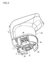
FIG. 9 is a perspective view of amotor housing 30 to which a motor assembly is attached,FIG. 10 is a vertical section taken in a right and left direction, andFIG. 11 is a vertical section taken in a front and rear direction. As seen in the drawings, abearing 31 for rotatably supporting a rotor (not shown) of a commutator motor is protrusively provided at a lower end of atubular motor housing 30. Themotor housing 30 is open at an upper end thereof. Themotor housing 30 has anattachment seat 32 peripherally around thebearing 31, and a disk-shapedbrush holder unit 35 for holding a pair ofbrushes attachment seat 32 and fixed by screwing bolts from beneath thebrush holder unit 35. In the meantime, anaccommodating portion 33 for the commutator motor is formed in themotor housing 30, andbosses accommodating portion 33, against which an end surface of astator 37 is in contact and fixed by screws. - Therefore, when the
brush holder unit 35 and thestator 37 are attached to themotor housing 30, as seen inFIGS. 12 and13 , thebrush holder unit 35 is fixed to theattachment seat 32 byscrews motor housing 30. On the contrary, thestator 37 is inserted into theaccommodating portion 33 from above themotor housing 30 and fixed to thebosses screws - As described above, the
brush holder unit 35 and thestator 37 are mounted from the opposite sides and fixed to themotor housing 30 by screws. This disadvantageously leads to deterioration of workability during assembly, an increased diameter of thestator 37 because of proving screw-threaded portions, and possible limitations on the construction of thebrush holder unit 35. - Further, since the
bearing 31 of the rotor is protrusively provided in themotor housing 30 at the middle of theattachment seat 32 of thebrush holder unit 35, a sufficient bearing rigidity is not obtained so that the operating life of thebrushes - It is thus an object of the present invention to provide an attachment structure for a motor assembly, by which a motor assembly comprising a commutator motor and a brush holder unit can be assembled with better workability, and by which an enhanced bearing rigidity can be obtained to ensure a sufficient operating life of the brushes, while avoiding increased diameter of the stator and possible limitations on the construction of the brush holder unit.
- In accordance with the present invention as embodied and described herein as a first embodiment, an attachment structure for a motor assembly, which allows a motor assembly including a commutator motor and a brush holder unit configured to hold brushes being slidable in contact with a commutator of the commutator motor to be attached in a tubular housing, comprises: an accommodating portion with a bottom, formed in the housing and configured to accommodate therein the motor assembly with the brush holder unit facing downward; a receiving portion formed in the accommodating portion and configured to position the brush holder unit when it comes into contact with the brush holder unit; an abutment portion at least formed on one of a stator of the commutator motor and the brush holder unit, and configured to come into contact with the corresponding brush holder unit or stator adjacent thereto during assembly for positioning between the stator and the brush holder unit; and a fixing member configured to be inserted from an open side of the housing, brought into contact with the stator, and fixed to the housing, wherein the motor assembly is positioned within the accommodating portion such that the brush holder unit is in contact with the receiving portion and that the stator and the brush holder unit are brought into contact with each other through the abutment portion, and wherein by fixing the motor assembly using the fixing member, the motor assembly is interposed and fixed between the fixing member and the receiving portion.
- Preferably, in a second embodiment, the attachment structure according to the first embodiment may be characterized in that the fixing member is a screw, which is inserted from the open side of the housing and screwed into the housing through the stator and the brush holder unit.
- Preferably, in a third embodiment, the attachment structure according to the second embodiment may be characterized in that the receiving portion and the abutment portion are in phase with each other, and that the screw is inserted through the stator and the brush holder unit at a position of the abutment portion and screwed into the receiving portion.
- Preferably, in a fourth embodiment, the attachment structure according to the first embodiment may be characterized in that a baffle plate is mounted to the housing near an opening of the housing, which covers an upstream side of a cooling fan that is provided on a rotor of the commutator motor, and that a second abutment portion is formed at least on one of the stator and the baffle plate, which comes into contact with the corresponding baffle plate or stator during assembly for positioning between the stator and the baffle plate, and the baffle plate functions as the fixing member such that by fixing the baffle plate to the housing, the motor assembly is interposed and fixed between the baffle plate and the receiving portion.
- With the aforementioned configuration of the attachment structure according to the first embodiment, it is possible to attach the motor assembly to the housing with better workability. Further, since the motor assembly is interposed and fixed between the fixing member and the receiving portion, it is not necessary to increase the diameter of the stator for the purpose of ensuring the screw-threaded portions and it is not subject to limitations on the construction of the brush holder unit. Furthermore, since it is not necessary to protrusively provide the bearing for the rotor on the housing, an enhanced bearing rigidity can be obtained, which results in less vibration on the rotor as well as in a sufficient operating life of the brushes.
- With the aforementioned configuration of the attachment structure according to the second embodiment, in addition to the above advantageous effects of the first embodiment, the motor assembly is fixed by the screw which is inserted through the stator and the brush holder unit and screwed into the housing, so that the motor assembly can be interposed and fixed between the screw and the receiving portion without suffering from backlash in the radial direction or the peripheral direction of the housing.
- With the aforementioned configuration of the attachment structure according to the third embodiment, in addition to the above advantageous effects of the second embodiment, the interposed position of the motor assembly by the screw and the abutment position between the component parts are in conformity with each other, so that a more stable assembly can be provided.
- Further, with the aforementioned configuration of the attachment structure according to the fourth embodiment, in addition to the above advantageous effects of the first embodiment, it is possible to provide an efficient attachment structure by which the motor assembly can be interposed and fixed between the fixing member and the receiving portion at the same time as assembling the conventional baffle plate.
- The above aspect, other advantages and further features of the present invention will become more apparent by describing in detail illustrative, non-limiting embodiments thereof with reference to the accompanying drawings, in which:
-
FIG. 1 is a perspective view of a motor housing; -
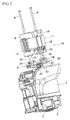
FIG. 2 is an exploded perspective view of an attachment structure for a motor assembly; -
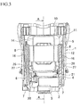
FIG. 3 is a vertical section taken in a right and left direction of the motor housing; -
FIG. 4 is a sectional view taken along the line A-A ofFIG. 3 ; -
FIG. 5 is a perspective view of the motor assembly; -
FIGS. 6A and 6B are perspective views of a brush holder unit, in whichFIG. 6A is a view from above, andFIG. 6B is a view from below; -
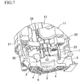
FIG. 7 is an enlarged perspective view illustrating an assembled state of the motor assembly; -
FIG. 8 is a partial perspective view according to a modification; -
FIG. 9 is a perspective view of a conventional motor housing; -
FIG. 10 is a vertical section of the conventional motor housing taken in a right and left direction; -
FIG. 11 is a vertical section of the conventional motor housing taken in a front and rear direction; -
FIG. 12 is an exploded perspective view of a conventional attachment structure for a motor assembly; and -
FIG. 13 is a perspective view illustrating an assembled state of the conventional motor assembly. - With reference to the accompanying drawings, exemplary embodiments of the present invention will be described in detail.
- In brief, an electric hammer is a well-known power tool which comprises: a
motor housing 1; a gear housing attached to an upper part of themotor housing 1 and in which a crank mechanism is disposed; a tubular housing attached to a front side (i.e., right side ofFIG. 1 ) of the gear housing and in which an impact mechanism is disposed; and a bit attached to a front side of the tubular housing and to which an impact force is exerted. A handle housing is attached to a rear surface of themotor housing 1. - As seen in
FIG. 1 , themotor housing 1 has a tubular shape of which a lower end is closed and an upper end is open. The lower end of themotor housing 1 provides a closedportion 2, and a supportingportion 3 configured to support a bearing for rotatably supporting a rotor of a commutator motor is depressingly provided at a center of the closedportion 2. A plurality ofair suction holes portion 3. - As best seen in
FIG. 2 , anaccommodating portion 5 with a bottom is formed in themotor housing 1. Theaccommodating portion 5 is configured to accommodate amotor assembly 10 including a commutator motor and abrush holder unit 20 by press fitting the respective parts with thebrush holder unit 20 facing downward. As seen inFIGS. 3 and4 , a pair ofbosses accommodating portion 5 in a point symmetrical arrangement. Each of thebosses - The commutator motor received in the
accommodating portion 5 includes astator 11 and a rotor (not shown). As seen inFIG. 5 , thestator 11 comprises acore 12 extending along its axis, a pair ofterminal plates core 12, a pair ofmain windings core 12, and a pair of sets ofmetal terminals FIGS. 5 , an upper side of the figure is referred to as an upper side when explaining themotor assembly 10. So isFIG. 6A ). Provided between each set ofmetal terminals hole 16 which axially penetrates through thecore 12 and theterminal plate 13 and opens from top to bottom. The throughholes bosses accommodating portion 5. - As seen in
FIGS. 6A and 6B , thebrush holder unit 20 has a ring-shapedbase 21 which is substantially the same size as theterminal plate 13 of thestator 11.Brush holders brush holders Reference number 23 is a spiral spring which is provided to the lateral of thebrush holder 22 and at its end portion urges the brush toward a center of the brush holder unit 22 (i.e., toward the commutator), andreference number 24 is a connecting portion having ametal terminal 25 and configured to be electrically connected to themetal terminals terminal plate 13 by inserting themetal terminals portion 24. A pair of spiral springs 23, 23 and a pair of connectingportions metal terminal 25 protrudes upward toward a switch, and the other portions of themetal terminal 25 extend toward thebrush holder 22, so as to create an electrical connection between them. - A
cylinder portion 26 as an abutment portion is provided between themetal terminals portion 24 at a lower side of thebase 21. Thecylinder portion 26 protrudes downward, and a throughhole 27 penetrates through thebase 21 and thecylinder portion 26 and opens from top to bottom. Thecylinder portion 26 is brought into contact with the upper surface of theterminal plate 13 of thestator 11 while adjusting phase. Further, arib 28 having a U-shaped configuration as seen from top is provided on the upper surface of the base 21 at a periphery of each throughhole 27. Therib 28 opens radially outward toward the circumference of thebase 21. Thebosses motor housing 1 are fitted into theribs - According to the
motor assembly 10 as described above, as seen inFIG. 5 , thebrush holder unit 20 is attached to the upper surface of thestator 11 while adjusting phase between the throughholes cylinder portions metal terminals terminal plate 13 to be inserted into the corresponding connectingportions cylinder portions terminal plate 13 for establishing communications between the throughholes - As best seen in
FIG. 7 , while adjusting phase between the throughholes bosses motor assembly 10 is inserted and press fitted into theaccommodating portion 5 of themotor housing 1 from an upper opening of themotor housing 1 with thebrush holder unit 20 facing downward. This can establish communications between the throughholes base 21 comes into engagement with thebosses accommodating portion 5 and thebosses ribs - In this state where the
motor assembly 10 is received in theaccommodating portion 5, twoscrews stator 11 into the throughholes bosses cylinder portions brush holder unit 20 and the throughholes stator 11 and thebrush holder unit 20 are fixed, as seen inFIGS. 3 and4 , while being interposed between thebosses screws stator 11 from above, and the lower end of the rotor is rotatably supported by the supportingportion 3, so that attachment of themotor assembly 10 is completed. - As described above, the attachment structure for the motor assembly 10 according to this exemplary embodiment is configured such that: the accommodating portion 5 with a bottom is formed in the motor housing 1, in which the motor assembly 10 is received with the brush holder unit 20 facing downward; that the bosses 6, 6 are formed in the accommodating portion 5 so as to contact with the brush holder unit 20 for positioning therebetween; that the cylinder portions 26, 26 are provided on the brush holder unit 20 so as to come into contact with the stator 11 adjacent thereto during assembly for positioning between the stator 11 and the brush holder unit 20; and that fixing members (screws 8, 8) are employed, which are inserted from an open side of the motor housing 1, brought into contact with the stator 11, and fixed to the motor housing 1; wherein the motor assembly 10 is positioned within the accommodating portion 5 such that the brush holder unit 20 is in contact with the bosses 6, 6 and that the stator 11 and the brush holder unit 20 are brought into contact with each other through the cylinder portions 26, 26, and wherein by fixing the motor assembly 10 using the screws 8, 8, the motor assembly 10 is interposed and fixed between the screws 8, 8 and the bosses 6, 6.
- With this configuration, the
motor assembly 10 comprising the commutator motor and thebrush holder unit 20 can be attached to themotor housing 1 with better workability. Further, since themotor assembly 10 is interposed and fixed between thescrews bosses stator 11 for the purpose of ensuring screw-threaded portions and it is not subject to limitations on the construction of thebrush holder unit 20. Furthermore, since it is not necessary to protrusively provide the bearing for the rotor on themotor housing 1, an enhanced bearing rigidity can be obtained, which results in less vibration on the rotor as well as in a sufficient operating life of the brushes. - In this exemplary embodiment, the fixing members are
screws motor housing 1 and screwed into themotor housing 1 through thestator 11 and thebrush holder unit 20, so that themotor assembly 10 can be interposed and fixed between thescrews bosses motor housing 1. - In this exemplary embodiment, since the
bosses cylinder portions screws stator 11 and thebrush holder unit 20 at positions of thecylinder portions bosses motor assembly 10 by thescrews - In the above exemplary embodiment, the
motor assembly 10 is inserted into and attached to themotor housing 1 after assembling thebrush holder unit 20 and thestator 11. However, as an alternative, thebrush holder unit 20 may be first attached to themotor housing 1, and then thestator 11 is inserted into and attached to themotor housing 1 and finally fixed by screws. - Further, the abutment portion is not limited to the cylinder portion, and various changes or modifications may be made. For example, a multi-sided tubular member or a pair of ribs between which a screw is inserted may be employed as the abutment portion. Such changes or modifications may also be made to the receiving portion. Of course, the number of the abutment portions and the receiving portions can be changed. Further, the abutment portion may be provided on an end surface of the
stator 11, instead of providing on thebrush holder unit 20. A pair of or pairs of corresponding abutment portions may be provided on opposed surfaces of thebrush holder unit 20 and thestator 11. - Further, it is not necessary that the abutment portion is in phase with the receiving portion. The abutment portion and the through hole for screw may be provided with different phases.
- In the above exemplary embodiment, each
screw 8 is inserted through thestator 11 and thebrush holder unit 20 and screwed into thecorresponding boss 6. However, it is not necessary that thescrews motor assembly 10. For example, screw-threaded portions may be formed on themotor housing 1 near an opening of themotor housing 1 and outside thestator 11, and a screw may be screwed into the corresponding screw-threaded portion through a washer so as to press the end surface of thestator 11 by the washer. Therefore, the stator is interposed between the screw-threaded portions and fixed by screws. In this instance, the screws and the washers function as the fixing members. - Another modification may be provided, in which the
motor assembly 10 is interposed and fixed between the fixing member and the receiving portion without employing screws penetrating through themotor assembly 10. In this example, a baffle plate for covering an upstream side of a cooling fan that is provided on the rotor of the commutator motor is mounted to themotor housing 1 near an opening of themotor housing 1. To be more specific, as best seen inFIG. 8 , a pair ofblock portions baffle plate 17 in a point symmetrical arrangement. Theblock portions stator 11 adjacent thereto during assembly. Meanwhile, screw-threadedportions motor housing 1 near an opening of themotor housing 1, against which theblock portions screws corresponding block portions portions - According to this modification, as with the above exemplary embodiment, the
brush holder unit 20 and thestator 11 are press fitted into themotor housing 1 until thebrush holder unit 20 comes into contact with thebosses baffle plate 17 is attached to the opening of themotor housing 1 in such a manner that theblock portions stator 11 and the screw-threadedportions screws motor housing 1 and screwed into the screw-threadedportions block portions motor assembly 10 is interposed and fixed between thebaffle plate 17 and thebosses - According to this modification, the
block portions baffle plate 17, which comes into contact withstator 11 adjacent thereto during assembly for positioning between thestator 11 and thebaffle plate 17, and thebaffle plate 17 functions as the fixing member such that by fixing thebaffle plate 17 to themotor housing 1, themotor assembly 10 is interposed and fixed between thebaffle plate 17 and thebosses motor assembly 10 to themotor housing 1 with better workability without increasing the diameter of thestator 11 and without limitations on the construction of thebrush holder unit 20. Further, as with the above exemplary embodiment, an enhanced bearing rigidity can be obtained, which results in less vibration on the rotor as well as in a sufficient operating life of the brushes. Especially, according to this modification, it is possible to provide an efficient attachment structure by which themotor assembly 10 can be interposed and fixed between thebaffle plate 17 and thebosses baffle plate 17 with themotor housing 1. - Various changes and modifications may also be made in this modification. For example, other than the
block portions stator 11, instead of providing on thebaffle plate 17. Of course, a pair of or pairs of corresponding second abutment portions may be provided on opposed surfaces of thebaffle plate 17 and thestator 11. Further, as long as thebaffle plate 17 is secured against the receiving portion, instead of using screws, thebaffle plate 17 may be attached and fixed to themotor housing 1 by other means such as a bayonet coupling. - The attachment structure according to the present invention may be applicable to other power tools other than the electric hammer.
- It is explicitly stated that all features disclosed in the description and/or the claims are intended to be disclosed separately and independently from each other for the purpose of original disclosure as well as for the purpose of restricting the claimed invention independent of the composition of the features in the embodiments and/or the claims. It is explicitly stated that all value ranges or indications of groups of entities disclose every possible intermediate value or intermediate entity for the purpose of original disclosure as well as for the purpose of restricting the claimed invention, in particular as limits of value ranges.
Claims (15)
- An attachment structure for a motor assembly (10), which allows a motor assembly (10) including a commutator motor and a brush holder unit (20) configured to hold brushes being slidable in contact with a commutator of the commutator motor to be attached in a tubular housing (1), comprising:an accommodating portion (5) with a bottom, formed in the housing (1) and configured to accommodate therein the motor assembly (10) with the brush holder unit (20) facing downward;a receiving portion (6) formed in the accommodating portion (5) and configured to position the brush holder unit (20) when it comes into contact with the brush holder unit (20);an abutment portion (26) at least formed on one of a stator (11) of the commutator motor and the brush holder unit (20), and configured to come into contact with the corresponding brush holder unit (20) or stator (11) adjacent thereto during assembly so that positioning is made between the stator (11) and the brush holder unit (20); anda fixing member (8, 9) configured to be inserted from an open side of the housing (1), brought into contact with the stator (11), and fixed to the housing (1),wherein the motor assembly (10) is positioned within the accommodating portion (5) such that the brush holder unit (20) is in contact with the receiving portion (6) and that the stator (11) and the brush holder unit (20) are brought into contact with each other through the abutment portion (26), andwherein by using the fixing member (8, 9), the motor assembly (10) is interposed and fixed between the fixing member (8, 9) and the receiving portion (6).
- The attachment structure for a motor assembly (10) according to claim 1, wherein the fixing member (8, 9) is a screw (8, 9), which is inserted from the open side of the housing (1) and screwed into the housing (1) through the stator (11) and the brush holder unit (20).
- The attachment structure for a motor assembly (10) according to claim 2, wherein the receiving portion (6) and the abutment portion (26) are in phase with each other, and wherein the screw (8, 9) is inserted through the stator (11) and the brush holder unit (20) at a position of the abutment portion (26) and screwed into the receiving portion (6).
- The attachment structure for a motor assembly (10) according to any one of claims 1 to 3, wherein a pair of receiving portions (6) and a pair of abutment portions (26) are formed in point symmetrical positions with respect to an axis of the housing (1).
- The attachment structure for a motor assembly (10) according to any one of claims 1 to 4, wherein the abutment portion (26) is a cylinder portion (26) provided on the brush holder unit (20).
- The attachment structure for a motor assembly (10) according to any one of claims 1 to 5, wherein a rib (28) is formed on the brush holder unit (20) at a position where the receiving portion (6) comes into contact with the brush holder unit (20), in such a manner that a periphery of the receiving portion (6) is surrounded by the rib (28) and the receiving portion (6) is fitted into the rib (28), wherein the rib (28) is preferably U-shaped.
- The attachment structure for a motor assembly (10) according to any one of claims 1 to 6, wherein the stator (11) comprises a core (12) extending along its axis, a pair of terminal plates (13) positioned at both ends of the core (12), a pair of main windings (14) wound around the core (12), and a pair of sets of metal terminals (15, 25) provided in point symmetrical positions on the terminal plate (13) that is positioned on the brush holder unit (20) side.
- The attachment structure for a motor assembly (10) according to claim 7, wherein a through hole (16, 27) for inserting the screw (8, 9) is formed between each set of metal terminals (15, 25), penetrating through the core (12) and the terminal plate (13).
- The attachment structure for a motor assembly (10) according to claim 7 or 8, wherein the brush holder unit (20) comprises a pair of connecting portions (24) having sets of metal terminals (15, 25) respectively, wherein the metal terminals (15, 25) of the connecting portions (24) are electrically connected to the metal terminals of the terminal plate (13).
- The attachment structure for a motor assembly (10) according to claim 9, wherein the abutment portion (26) is provided at each connecting portion (24) between each set of metal terminals (15, 25).
- The attachment structure for a motor assembly (10) according to claim 2, wherein the receiving portion (6) and the abutment portion (26) are not in phase with each other.
- The attachment structure for a motor assembly (10) according to claim 1, wherein a baffle plate (17) is mounted to the housing (1) near an opening of the housing (1), which covers an upstream side of a cooling fan that is provided on a rotor of the commutator motor.
- The attachment structure for a motor assembly (10) according to claim 12, wherein a second abutment portion is formed at least on one of the stator (11) and the baffle plate (17), which comes into contact with the corresponding baffle plate (17) or stator (11) during assembly for positioning between the stator (11) and the baffle plate (17), and wherein the baffle plate (17) functions as the fixing member (8, 9) such that by fixing the baffle plate (17) to the housing (1), the motor assembly (10) is interposed and fixed between the baffle plate (17) and the receiving portion (6).
- The attachment structure for a motor assembly (10) according to claim 13, wherein a screw-threaded portion (19) is formed on the housing (1) near the opening of the housing (1), against which the second abutment portion is brought into contact, and wherein a screw (8, 9) is inserted through the second abutment portion and screwed into the screw-threaded portion (19) to secure the baffle plate (17).
- The attachment structure for a motor assembly (10) according to claim 13 or 14, wherein the second abutment portion comprises a pair of block portions (18).
Applications Claiming Priority (1)
| Application Number | Priority Date | Filing Date | Title |
|---|---|---|---|
| JP2009154175A JP5319422B2 (en) | 2009-06-29 | 2009-06-29 | Motor assembly assembly structure |
Publications (2)
| Publication Number | Publication Date |
|---|---|
| EP2269782A1 true EP2269782A1 (en) | 2011-01-05 |
| EP2269782B1 EP2269782B1 (en) | 2018-08-08 |
Family
ID=42623402
Family Applications (1)
| Application Number | Title | Priority Date | Filing Date |
|---|---|---|---|
| EP10166823.4A Active EP2269782B1 (en) | 2009-06-29 | 2010-06-22 | Attachment structure for motor assembly |
Country Status (5)
| Country | Link |
|---|---|
| US (1) | US8373327B2 (en) |
| EP (1) | EP2269782B1 (en) |
| JP (1) | JP5319422B2 (en) |
| CN (1) | CN101938196B (en) |
| RU (1) | RU2532772C2 (en) |
Families Citing this family (3)
| Publication number | Priority date | Publication date | Assignee | Title |
|---|---|---|---|---|
| JP7149873B2 (en) * | 2019-02-14 | 2022-10-07 | 株式会社マキタ | Electric tool |
| US11691262B2 (en) | 2019-09-26 | 2023-07-04 | Makita Corporation | Electric power tool |
| JP7365834B2 (en) * | 2019-09-26 | 2023-10-20 | 株式会社マキタ | Electric tool |
Citations (8)
| Publication number | Priority date | Publication date | Assignee | Title |
|---|---|---|---|---|
| DE29702947U1 (en) * | 1997-02-21 | 1998-06-18 | Robert Bosch Gmbh, 70469 Stuttgart | Angle grinder |
| US6713916B1 (en) * | 2002-10-31 | 2004-03-30 | Black & Decker Inc. | Electric motor assembly |
| US20040171299A1 (en) * | 1999-12-01 | 2004-09-02 | Milwaukee Electric Tool Corporation | Method for assembling and electrical connector assembly for a power tool |
| EP1598151A2 (en) * | 2004-05-20 | 2005-11-23 | BLACK & DECKER INC. | Motor housing and assembly process for impact wrench |
| JP2007143314A (en) | 2005-11-18 | 2007-06-07 | Makita Corp | Forward-backward rotation switching device for power tool |
| DE102007001388A1 (en) * | 2006-01-11 | 2007-07-12 | Hitachi Koki Co., Ltd. | Electric power tool e.g. percussion drilling machine, has fan guide connected with yoke end surface in axial direction and staying in contact with yoke in circumferential direction, and recess section formed in yoke end surface |
| US20070188027A1 (en) * | 2006-02-13 | 2007-08-16 | Asmo Co., Ltd. | Motor |
| DE102006000543A1 (en) * | 2006-12-21 | 2008-06-26 | Hilti Ag | Hand tool device has multipart housing, which has motor housing, forming assembly opening, over which stator of motor is inserted in motor housing |
Family Cites Families (10)
| Publication number | Priority date | Publication date | Assignee | Title |
|---|---|---|---|---|
| US4498230A (en) * | 1982-01-08 | 1985-02-12 | Black & Decker Inc. | Assembling brush box sub-assemblies in electric motors |
| DE3300494A1 (en) * | 1983-01-08 | 1984-07-12 | Robert Bosch Gmbh, 7000 Stuttgart | THREE-PHASE GENERATOR FOR VEHICLES, ESPECIALLY WITH A CLAW-POLE RUNNER |
| JPS6110928A (en) * | 1984-06-25 | 1986-01-18 | Matsushita Electric Works Ltd | Stator for motor |
| JPH0739320Y2 (en) * | 1986-07-08 | 1995-09-06 | 三菱電機株式会社 | Flat motor |
| SU1399837A1 (en) * | 1986-08-07 | 1988-05-30 | Ташкентский институт инженеров железнодорожного транспорта | Assembly for securing brush holder on electric machine stator |
| JP3792282B2 (en) * | 1995-02-17 | 2006-07-05 | 本田技研工業株式会社 | Vehicle starter and generator |
| JPH1023691A (en) * | 1996-06-28 | 1998-01-23 | Shibaura Eng Works Co Ltd | DC motor |
| JP3877554B2 (en) * | 2001-08-10 | 2007-02-07 | 東芝テック株式会社 | Stator, motor and electric blower |
| US7063170B2 (en) * | 2003-02-26 | 2006-06-20 | Black & Decker Inc. | Flexible power tool motor pack and method of making the same |
| RU68803U1 (en) * | 2007-06-25 | 2007-11-27 | Общество с ограниченной ответственностью "Сибирская электротехническая компания" (ООО "СЭТК") | MOTOR-BRUSHED BRANCH ASSEMBLY |
-
2009
- 2009-06-29 JP JP2009154175A patent/JP5319422B2/en active Active
-
2010
- 2010-04-19 CN CN201010151074.7A patent/CN101938196B/en active Active
- 2010-06-02 US US12/792,180 patent/US8373327B2/en active Active
- 2010-06-22 EP EP10166823.4A patent/EP2269782B1/en active Active
- 2010-06-28 RU RU2010126454/02A patent/RU2532772C2/en active
Patent Citations (8)
| Publication number | Priority date | Publication date | Assignee | Title |
|---|---|---|---|---|
| DE29702947U1 (en) * | 1997-02-21 | 1998-06-18 | Robert Bosch Gmbh, 70469 Stuttgart | Angle grinder |
| US20040171299A1 (en) * | 1999-12-01 | 2004-09-02 | Milwaukee Electric Tool Corporation | Method for assembling and electrical connector assembly for a power tool |
| US6713916B1 (en) * | 2002-10-31 | 2004-03-30 | Black & Decker Inc. | Electric motor assembly |
| EP1598151A2 (en) * | 2004-05-20 | 2005-11-23 | BLACK & DECKER INC. | Motor housing and assembly process for impact wrench |
| JP2007143314A (en) | 2005-11-18 | 2007-06-07 | Makita Corp | Forward-backward rotation switching device for power tool |
| DE102007001388A1 (en) * | 2006-01-11 | 2007-07-12 | Hitachi Koki Co., Ltd. | Electric power tool e.g. percussion drilling machine, has fan guide connected with yoke end surface in axial direction and staying in contact with yoke in circumferential direction, and recess section formed in yoke end surface |
| US20070188027A1 (en) * | 2006-02-13 | 2007-08-16 | Asmo Co., Ltd. | Motor |
| DE102006000543A1 (en) * | 2006-12-21 | 2008-06-26 | Hilti Ag | Hand tool device has multipart housing, which has motor housing, forming assembly opening, over which stator of motor is inserted in motor housing |
Also Published As
| Publication number | Publication date |
|---|---|
| RU2010126454A (en) | 2012-01-10 |
| CN101938196B (en) | 2014-02-12 |
| RU2532772C2 (en) | 2014-11-10 |
| EP2269782B1 (en) | 2018-08-08 |
| US20100327685A1 (en) | 2010-12-30 |
| JP5319422B2 (en) | 2013-10-16 |
| CN101938196A (en) | 2011-01-05 |
| US8373327B2 (en) | 2013-02-12 |
| JP2011010530A (en) | 2011-01-13 |
Similar Documents
| Publication | Publication Date | Title |
|---|---|---|
| JP3515425B2 (en) | Motor storage structure | |
| US6677693B2 (en) | Motor | |
| EP3787153B1 (en) | Brushed permanent magnet micromotor and assembly method therefor | |
| JPH0753402Y2 (en) | Brush device | |
| CN205438465U (en) | Electric tool | |
| EP1814211A2 (en) | Noise suppression structure of blower motor | |
| EP2396870B1 (en) | Brush holder assembly for a dynamo-electric machine | |
| JP5522342B2 (en) | Motor power supply terminal connection parts for receiving electric power of motor, brush holder, and motor using them | |
| CA2298750A1 (en) | Method for assembling and electrical connector for a power tool | |
| US7049727B2 (en) | Integrated brush-holder retention system | |
| US8373327B2 (en) | Attachment structure for motor assembly | |
| EP2667490B1 (en) | Brush assembly for a power tool motor | |
| CN101933216A (en) | Motor | |
| JP6856067B2 (en) | Motor and motor manufacturing method | |
| US9484785B2 (en) | Electric motor | |
| JP2012191792A (en) | Electric power supply means and motor unit | |
| JP6105800B1 (en) | Motor assembly | |
| JP2005530470A (en) | Electric motor for handheld machine tools | |
| US7545071B2 (en) | Brush holder device for use in small-size motor | |
| EP0510984A1 (en) | Miniature electric motor | |
| US7987918B2 (en) | Electric hand-held power tool | |
| JP6370020B2 (en) | motor | |
| CN222515209U (en) | Motor rotor structure | |
| CN101361249A (en) | Commutator Motor Stator End Plates and Commutator Motors | |
| CN110581620A (en) | Brush assembly, motor comprising same and electric power steering system |
Legal Events
| Date | Code | Title | Description |
|---|---|---|---|
| PUAI | Public reference made under article 153(3) epc to a published international application that has entered the european phase |
Free format text: ORIGINAL CODE: 0009012 |
|
| AK | Designated contracting states |
Kind code of ref document: A1 Designated state(s): AL AT BE BG CH CY CZ DE DK EE ES FI FR GB GR HR HU IE IS IT LI LT LU LV MC MK MT NL NO PL PT RO SE SI SK SM TR |
|
| AX | Request for extension of the european patent |
Extension state: BA ME RS |
|
| 17P | Request for examination filed |
Effective date: 20110125 |
|
| 17Q | First examination report despatched |
Effective date: 20140226 |
|
| STAA | Information on the status of an ep patent application or granted ep patent |
Free format text: STATUS: EXAMINATION IS IN PROGRESS |
|
| GRAP | Despatch of communication of intention to grant a patent |
Free format text: ORIGINAL CODE: EPIDOSNIGR1 |
|
| STAA | Information on the status of an ep patent application or granted ep patent |
Free format text: STATUS: GRANT OF PATENT IS INTENDED |
|
| INTG | Intention to grant announced |
Effective date: 20180509 |
|
| GRAS | Grant fee paid |
Free format text: ORIGINAL CODE: EPIDOSNIGR3 |
|
| GRAA | (expected) grant |
Free format text: ORIGINAL CODE: 0009210 |
|
| STAA | Information on the status of an ep patent application or granted ep patent |
Free format text: STATUS: THE PATENT HAS BEEN GRANTED |
|
| AK | Designated contracting states |
Kind code of ref document: B1 Designated state(s): AL AT BE BG CH CY CZ DE DK EE ES FI FR GB GR HR HU IE IS IT LI LT LU LV MC MK MT NL NO PL PT RO SE SI SK SM TR |
|
| REG | Reference to a national code |
Ref country code: GB Ref legal event code: FG4D |
|
| REG | Reference to a national code |
Ref country code: CH Ref legal event code: EP Ref country code: AT Ref legal event code: REF Ref document number: 1026461 Country of ref document: AT Kind code of ref document: T Effective date: 20180815 |
|
| REG | Reference to a national code |
Ref country code: IE Ref legal event code: FG4D |
|
| REG | Reference to a national code |
Ref country code: DE Ref legal event code: R096 Ref document number: 602010052473 Country of ref document: DE |
|
| REG | Reference to a national code |
Ref country code: NL Ref legal event code: MP Effective date: 20180808 |
|
| REG | Reference to a national code |
Ref country code: LT Ref legal event code: MG4D |
|
| REG | Reference to a national code |
Ref country code: AT Ref legal event code: MK05 Ref document number: 1026461 Country of ref document: AT Kind code of ref document: T Effective date: 20180808 |
|
| PG25 | Lapsed in a contracting state [announced via postgrant information from national office to epo] |
Ref country code: FI Free format text: LAPSE BECAUSE OF FAILURE TO SUBMIT A TRANSLATION OF THE DESCRIPTION OR TO PAY THE FEE WITHIN THE PRESCRIBED TIME-LIMIT Effective date: 20180808 Ref country code: IS Free format text: LAPSE BECAUSE OF FAILURE TO SUBMIT A TRANSLATION OF THE DESCRIPTION OR TO PAY THE FEE WITHIN THE PRESCRIBED TIME-LIMIT Effective date: 20181208 Ref country code: AT Free format text: LAPSE BECAUSE OF FAILURE TO SUBMIT A TRANSLATION OF THE DESCRIPTION OR TO PAY THE FEE WITHIN THE PRESCRIBED TIME-LIMIT Effective date: 20180808 Ref country code: NO Free format text: LAPSE BECAUSE OF FAILURE TO SUBMIT A TRANSLATION OF THE DESCRIPTION OR TO PAY THE FEE WITHIN THE PRESCRIBED TIME-LIMIT Effective date: 20181108 Ref country code: GR Free format text: LAPSE BECAUSE OF FAILURE TO SUBMIT A TRANSLATION OF THE DESCRIPTION OR TO PAY THE FEE WITHIN THE PRESCRIBED TIME-LIMIT Effective date: 20181109 Ref country code: BG Free format text: LAPSE BECAUSE OF FAILURE TO SUBMIT A TRANSLATION OF THE DESCRIPTION OR TO PAY THE FEE WITHIN THE PRESCRIBED TIME-LIMIT Effective date: 20181108 Ref country code: SE Free format text: LAPSE BECAUSE OF FAILURE TO SUBMIT A TRANSLATION OF THE DESCRIPTION OR TO PAY THE FEE WITHIN THE PRESCRIBED TIME-LIMIT Effective date: 20180808 Ref country code: NL Free format text: LAPSE BECAUSE OF FAILURE TO SUBMIT A TRANSLATION OF THE DESCRIPTION OR TO PAY THE FEE WITHIN THE PRESCRIBED TIME-LIMIT Effective date: 20180808 Ref country code: LT Free format text: LAPSE BECAUSE OF FAILURE TO SUBMIT A TRANSLATION OF THE DESCRIPTION OR TO PAY THE FEE WITHIN THE PRESCRIBED TIME-LIMIT Effective date: 20180808 Ref country code: PL Free format text: LAPSE BECAUSE OF FAILURE TO SUBMIT A TRANSLATION OF THE DESCRIPTION OR TO PAY THE FEE WITHIN THE PRESCRIBED TIME-LIMIT Effective date: 20180808 |
|
| PG25 | Lapsed in a contracting state [announced via postgrant information from national office to epo] |
Ref country code: HR Free format text: LAPSE BECAUSE OF FAILURE TO SUBMIT A TRANSLATION OF THE DESCRIPTION OR TO PAY THE FEE WITHIN THE PRESCRIBED TIME-LIMIT Effective date: 20180808 Ref country code: LV Free format text: LAPSE BECAUSE OF FAILURE TO SUBMIT A TRANSLATION OF THE DESCRIPTION OR TO PAY THE FEE WITHIN THE PRESCRIBED TIME-LIMIT Effective date: 20180808 Ref country code: ES Free format text: LAPSE BECAUSE OF FAILURE TO SUBMIT A TRANSLATION OF THE DESCRIPTION OR TO PAY THE FEE WITHIN THE PRESCRIBED TIME-LIMIT Effective date: 20180808 Ref country code: AL Free format text: LAPSE BECAUSE OF FAILURE TO SUBMIT A TRANSLATION OF THE DESCRIPTION OR TO PAY THE FEE WITHIN THE PRESCRIBED TIME-LIMIT Effective date: 20180808 |
|
| PG25 | Lapsed in a contracting state [announced via postgrant information from national office to epo] |
Ref country code: CZ Free format text: LAPSE BECAUSE OF FAILURE TO SUBMIT A TRANSLATION OF THE DESCRIPTION OR TO PAY THE FEE WITHIN THE PRESCRIBED TIME-LIMIT Effective date: 20180808 Ref country code: IT Free format text: LAPSE BECAUSE OF FAILURE TO SUBMIT A TRANSLATION OF THE DESCRIPTION OR TO PAY THE FEE WITHIN THE PRESCRIBED TIME-LIMIT Effective date: 20180808 Ref country code: RO Free format text: LAPSE BECAUSE OF FAILURE TO SUBMIT A TRANSLATION OF THE DESCRIPTION OR TO PAY THE FEE WITHIN THE PRESCRIBED TIME-LIMIT Effective date: 20180808 Ref country code: EE Free format text: LAPSE BECAUSE OF FAILURE TO SUBMIT A TRANSLATION OF THE DESCRIPTION OR TO PAY THE FEE WITHIN THE PRESCRIBED TIME-LIMIT Effective date: 20180808 |
|
| REG | Reference to a national code |
Ref country code: DE Ref legal event code: R097 Ref document number: 602010052473 Country of ref document: DE |
|
| PG25 | Lapsed in a contracting state [announced via postgrant information from national office to epo] |
Ref country code: DK Free format text: LAPSE BECAUSE OF FAILURE TO SUBMIT A TRANSLATION OF THE DESCRIPTION OR TO PAY THE FEE WITHIN THE PRESCRIBED TIME-LIMIT Effective date: 20180808 Ref country code: SM Free format text: LAPSE BECAUSE OF FAILURE TO SUBMIT A TRANSLATION OF THE DESCRIPTION OR TO PAY THE FEE WITHIN THE PRESCRIBED TIME-LIMIT Effective date: 20180808 Ref country code: SK Free format text: LAPSE BECAUSE OF FAILURE TO SUBMIT A TRANSLATION OF THE DESCRIPTION OR TO PAY THE FEE WITHIN THE PRESCRIBED TIME-LIMIT Effective date: 20180808 |
|
| PLBE | No opposition filed within time limit |
Free format text: ORIGINAL CODE: 0009261 |
|
| STAA | Information on the status of an ep patent application or granted ep patent |
Free format text: STATUS: NO OPPOSITION FILED WITHIN TIME LIMIT |
|
| 26N | No opposition filed |
Effective date: 20190509 |
|
| PG25 | Lapsed in a contracting state [announced via postgrant information from national office to epo] |
Ref country code: SI Free format text: LAPSE BECAUSE OF FAILURE TO SUBMIT A TRANSLATION OF THE DESCRIPTION OR TO PAY THE FEE WITHIN THE PRESCRIBED TIME-LIMIT Effective date: 20180808 |
|
| PG25 | Lapsed in a contracting state [announced via postgrant information from national office to epo] |
Ref country code: MC Free format text: LAPSE BECAUSE OF FAILURE TO SUBMIT A TRANSLATION OF THE DESCRIPTION OR TO PAY THE FEE WITHIN THE PRESCRIBED TIME-LIMIT Effective date: 20180808 |
|
| REG | Reference to a national code |
Ref country code: CH Ref legal event code: PL |
|
| REG | Reference to a national code |
Ref country code: BE Ref legal event code: MM Effective date: 20190630 |
|
| PG25 | Lapsed in a contracting state [announced via postgrant information from national office to epo] |
Ref country code: TR Free format text: LAPSE BECAUSE OF FAILURE TO SUBMIT A TRANSLATION OF THE DESCRIPTION OR TO PAY THE FEE WITHIN THE PRESCRIBED TIME-LIMIT Effective date: 20180808 |
|
| PG25 | Lapsed in a contracting state [announced via postgrant information from national office to epo] |
Ref country code: IE Free format text: LAPSE BECAUSE OF NON-PAYMENT OF DUE FEES Effective date: 20190622 |
|
| PG25 | Lapsed in a contracting state [announced via postgrant information from national office to epo] |
Ref country code: LU Free format text: LAPSE BECAUSE OF NON-PAYMENT OF DUE FEES Effective date: 20190622 Ref country code: BE Free format text: LAPSE BECAUSE OF NON-PAYMENT OF DUE FEES Effective date: 20190630 Ref country code: LI Free format text: LAPSE BECAUSE OF NON-PAYMENT OF DUE FEES Effective date: 20190630 Ref country code: CH Free format text: LAPSE BECAUSE OF NON-PAYMENT OF DUE FEES Effective date: 20190630 |
|
| PG25 | Lapsed in a contracting state [announced via postgrant information from national office to epo] |
Ref country code: PT Free format text: LAPSE BECAUSE OF FAILURE TO SUBMIT A TRANSLATION OF THE DESCRIPTION OR TO PAY THE FEE WITHIN THE PRESCRIBED TIME-LIMIT Effective date: 20181208 |
|
| PG25 | Lapsed in a contracting state [announced via postgrant information from national office to epo] |
Ref country code: CY Free format text: LAPSE BECAUSE OF FAILURE TO SUBMIT A TRANSLATION OF THE DESCRIPTION OR TO PAY THE FEE WITHIN THE PRESCRIBED TIME-LIMIT Effective date: 20180808 |
|
| PG25 | Lapsed in a contracting state [announced via postgrant information from national office to epo] |
Ref country code: MT Free format text: LAPSE BECAUSE OF FAILURE TO SUBMIT A TRANSLATION OF THE DESCRIPTION OR TO PAY THE FEE WITHIN THE PRESCRIBED TIME-LIMIT Effective date: 20180808 Ref country code: HU Free format text: LAPSE BECAUSE OF FAILURE TO SUBMIT A TRANSLATION OF THE DESCRIPTION OR TO PAY THE FEE WITHIN THE PRESCRIBED TIME-LIMIT; INVALID AB INITIO Effective date: 20100622 |
|
| PG25 | Lapsed in a contracting state [announced via postgrant information from national office to epo] |
Ref country code: MK Free format text: LAPSE BECAUSE OF FAILURE TO SUBMIT A TRANSLATION OF THE DESCRIPTION OR TO PAY THE FEE WITHIN THE PRESCRIBED TIME-LIMIT Effective date: 20180808 |
|
| PGFP | Annual fee paid to national office [announced via postgrant information from national office to epo] |
Ref country code: DE Payment date: 20250429 Year of fee payment: 16 |
|
| PGFP | Annual fee paid to national office [announced via postgrant information from national office to epo] |
Ref country code: GB Payment date: 20250501 Year of fee payment: 16 |
|
| PGFP | Annual fee paid to national office [announced via postgrant information from national office to epo] |
Ref country code: FR Payment date: 20250508 Year of fee payment: 16 |