EP2268893B1 - Selectively angled perforating - Google Patents
Selectively angled perforating Download PDFInfo
- Publication number
- EP2268893B1 EP2268893B1 EP09724850.4A EP09724850A EP2268893B1 EP 2268893 B1 EP2268893 B1 EP 2268893B1 EP 09724850 A EP09724850 A EP 09724850A EP 2268893 B1 EP2268893 B1 EP 2268893B1
- Authority
- EP
- European Patent Office
- Prior art keywords
- perforating
- formation
- wellbore
- boundary
- gun
- Prior art date
- Legal status (The legal status is an assumption and is not a legal conclusion. Google has not performed a legal analysis and makes no representation as to the accuracy of the status listed.)
- Not-in-force
Links
Images
Classifications
-
- E—FIXED CONSTRUCTIONS
- E21—EARTH OR ROCK DRILLING; MINING
- E21B—EARTH OR ROCK DRILLING; OBTAINING OIL, GAS, WATER, SOLUBLE OR MELTABLE MATERIALS OR A SLURRY OF MINERALS FROM WELLS
- E21B43/00—Methods or apparatus for obtaining oil, gas, water, soluble or meltable materials or a slurry of minerals from wells
- E21B43/11—Perforators; Permeators
- E21B43/119—Details, e.g. for locating perforating place or direction
Definitions
- the invention relates generally to the field of oil and gas production. More specifically, the present invention relates to a method of perforating a wellbore. Yet more specifically, the invention concerns aligning perforations based on one or more reservoir characteristics.
- Perforating systems are used for the purpose, among others, of making hydraulic communication passages, called perforations, in wellbores drilled through earth formations so that predetermined zones of the earth formations can be hydraulically connected to the wellbore. Perforations are needed because wellbores are typically completed by coaxially inserting a pipe or casing into the wellbore.
- the casing is retained in the wellbore by pumping cement into the annular space between the wellbore and the casing.
- the cemented casing is provided in the wellbore for the specific purpose of hydraulically isolating from each other the various earth formations penetrated by the wellbore.
- Perforating systems typically comprise one or more perforating guns strung together, these strings of guns can sometimes surpass a thousand feet (305m) of perforating length
- FIG 1 an example of a perforating system 4 is shown.
- the system 4 depicted comprises a single perforating gun 6 instead of a multitude of guns.
- the gun 6 is shown disposed within a wellbore 1 on a wire line 5.
- the perforating system 4 as shown also includes a service truck 7 on the surface 9, where in addition to providing a raising and lowering means, the wire line 5 also provides communication and control connectivity between the truck 7 and the perforating gun 6.
- the wire line 5 is threaded through pulleys 3 supported above the wellbore 1.
- perforating systems may also be disposed into a wellbore via tubing, drill pipe, slick line, coiled tubing, to mention a few.
- shaped charges 8 that typically include a housing, a liner, and a quantity of high explosive inserted between the liner and the housing.
- the force of the detonation collapses the liner and ejects it from one end of the charge 8 at very high velocity in a pattern called a "jet" 12.
- the jet 12 perforates the casing and the cement and creates a perforation 10 that extends into the surrounding formation 2.
- the wellbore pressure is different from the pressure within the formation 2, thus upon perforation pressure equalization occurs between the formation and the wellbore which in turn produces either flow into the wellbore from the formation, or into the formation from the wellbore.
- a method of perforating a wellbore wherein the perforations are aligned with a characteristic of a reservoir.
- the perforations are aligned with a reservoir characteristic such as the direction of maximum stress or the formation dip.
- the method of perforating a wellbore involves forming a perforation in the wellbore, where the perforation is aligned with the direction of maximum stress or the formation dip.
- the method may further comprise disposing a perforating system in the wellbore, the perforating system comprising a shaped charge, aiming the shaped charge for alignment with the direction of maximum stress or the formation dip, and detonating the shaped charge.
- the perforating system may further comprise a body housing the shaped charge with the method further comprising orienting the body to aim the shaped charge for alignment with the direction of maximum stress or the formation dip. Perforating is performed with a shaped charge.
- the charges may be rotated about a pivot point for orientation purposes.
- the subterranean formations 2 intersected by the wellbore 1 comprise a series of individual and distinct layers or formations 14.
- Boundary lines 16 are provided between adjacent formations 14 illustrating a border thereby defining the contour of the formations 14.
- Each individual formation 14 is defined as a body of subterranean strata, such as rock, comprising predominantly a single type or types of composition.
- the formation 14 could comprise a type or types of rock having relatively consistent properties throughout that formation 14. Examples of characteristics include permeability, density, porosity, resistivity, saturation, dip angle, stress, and combinations thereof.
- a formation 14 may be comprised of low density material other than rock, such as sand, sediment, sedimentary rock, stratum, or sandstone.
- the formation 14 can be any stratigraphic unit, including a bed, wherein the beds are distinguishable from one another.
- the formations 14 and boundaries 16 as illustrated are oriented generally oblique to the axis A x of the wellbore 1; perforations 10 are shown formed through the wellbore 1 and into the formation may cross one or more boundary lines 16. These perforations 10 that intersect one or more boundary lines 16 may pass through adjacent strata with different and distinctive properties, thereby affecting the permeability from the strata into the perforation 10.
- the method and apparatus disclosed herein includes a manner of perforating with respect to a subterranean formation characteristic.
- the formation characteristics include formation bedding, formation dip angles, directions of constant stress, including a direction of maximum stress, and isotropic zones such as zones of constant density, porosity, permeability, saturation, and the like.
- the step of perforating thus includes aiming shaped charges with respect to a line(s) or plane(s) defining the formation characteristic. Aiming may include aligning shaped charges with a formation characteristic, or at a desired angle from a formation characteristic.
- a plane of maximum stress is defined herein as a plane in which the formation stress exceeds that in an adjacent formation(s).
- the direction of maximum stress denotes the plane's general trajectory along a line within the formation.
- FIG 2 provides a side partial cross-sectional view of a perforating system 4a disposed in a wellbore 1.
- the perforating system 4a includes a perforating gun 6a having shaped charges 8 aimed with the intent of forming a jet 12a that dodges boundary lines 16.
- Forming a perforating jet 12a that avoids the boundary lines 16 creates perforations 10a lying within a single identifiable formation 14 and thus can also be within a single formation characteristic.
- the shaped charge 8 can be aimed so its jet 12a is aligned with the formation 14.
- One example of alignment comprises a perforation 10a parallel with one or both of the boundary lines 16 lying adjacent to the particular formation 14.
- the shaped charge 8 is aimed to form a jet 12a largely parallel with the formation 14 dip angle.
- the dip angle may be defined as the angle at which the formation 14 and/or boundary line 16 lies relative to the axis A x of the wellbore 1. This is sometimes also referred to as the dip of the formation.
- Perforating into the formation 14 at its dip angle aligns the perforation 10a to the optimal permeability of the reservoir from which hydrocarbons are to be produced. This results in an enhanced and increased flow of hydrocarbons through the perforations 10a and into the wellbore 10a for production of the hydrocarbons.
- a gyroscope (not shown) can be included with the perforating system 4a to provide orientation control within the wellbore 1.
- the perforating system 4a of Figure 2 is not limited to a single gun body, but can include multiple gun bodies strung together adjacently as part of a larger string. Other downhole tools may also be provided in the tool string.
- the perforating method described herein is not limited to a vertical wellbore, but can be in deviated as well as horizontal wellbores. As such, the perforating system 4a may be disposed on wire line as well as any type of tubing, including coiled tubing and a tractor device.
- FIG. 3 An embodiment in accordance with the invention is provided in side view in Figure 3 illustrating shaped charges 8a statically affixed within a gun body 6b at an angle oblique to the gun body axis A x1 .
- the shaped charges 8a are disposed in a charge tube that is cylindrical and machined to hold the charges 8a pointing at a desired attitude relative to the gun body axis A x1 .
- This orientation angle can form perforations 10a aligned with the dip angle of the formation 14.
- the charge tube 18 in this embodiment is longitudinally split into two or more parts (20, 22) having end fittings 32 at each end to allow the two pieces (20, 22) to be secured at different longitudinal positions with respect to one another.
- the shaped charge 8a ends are shown engaged with holes (24, 25, 26, 27) formed through the charge tube 18 body.
- holes (24, 25, 26, 27) formed through the charge tube 18 body.
- selective longitudinal placement of the charge tube 18 parts (20, 22) in turn angles the shape charges 8a oblique to the axis A x1 .
- This shifting angularly cants the charges 8a for a desired alignment to be shot by the charges 8a.
- the angle of the shaped charge 8a can be controlled and selected by adding drilled and tap holes 30 formed to receive screws or bolts 31 in the end fittings 32.
- Figure 4 provides a partial cross sectional view of an example of perforating with respect to a formation characteristic.
- a perforating system 4b is disposed in a wellbore 1.
- Illustrated are jets 12b forming perforations 10b in a reservoir 36 surrounding the wellbore 1.
- the jets 12b emanate from shaped charges 8b in a perforating gun 6b.
- a direction of maximum stress 34 in the reservoir 36 is shown intersecting the wellbore 1.
- the direction of maximum stress 34 is generally oblique to the wellbore axis A x .
- the shaped charges 8b have been oriented and/or aligned within the perforating gun 6b so the jets 12b are either substantially aligned with the direction of maximum stress 34 or extend generally parallel to the direction 34.
- the shot phasing on the gun 6b may be at 0° and 180°.
- the shaped charges 8b at either 0° or 180° may be aligned with the plane and oriented to form a perforation 10b in the plane 34 coincident with the azimuth radial position where the angle between the direction 34 and the wellbore axis A x is at a minimum.
- the embodiment of Figure 4 as an example, if the 0° phased shot is directed azimuthally as described above and angled upward, the shot at 180° phasing would also be aligned in the plane and directed downward.
- FIG. 5 is a cross sectional view of an embodiment of a perforating system 4a in accordance with the present disclosure disposed in a deviated wellbore 1a.
- the perforating gun 6a is disposed on wireline 5 in the deviated portion of the wellbore 1a.
- a coordinate axis V A and H A are provided that represent potential shot direction.
- V A is largely parallel with vertical axis at surface 42 and H A is largely parallel with horizontal axis at surface 42.
- a dashed axis V A ' and H A ' graphically illustrate ranges of shot angles (A 1 , A 2 ) possible with a perforating device, such as an angled perforating system as described herein.
- a 1 and A 2 are greater than 90°, and may be equal in some instances.
- implementation of the angled shaped charges provides for shot angles that exceed vertical and horizontal alignments.
Landscapes
- Life Sciences & Earth Sciences (AREA)
- Engineering & Computer Science (AREA)
- Geology (AREA)
- Mining & Mineral Resources (AREA)
- Physics & Mathematics (AREA)
- Environmental & Geological Engineering (AREA)
- Fluid Mechanics (AREA)
- General Life Sciences & Earth Sciences (AREA)
- Geochemistry & Mineralogy (AREA)
- Drilling And Exploitation, And Mining Machines And Methods (AREA)
- Physical Or Chemical Processes And Apparatus (AREA)
- Earth Drilling (AREA)
Description
- The invention relates generally to the field of oil and gas production. More specifically, the present invention relates to a method of perforating a wellbore. Yet more specifically, the invention concerns aligning perforations based on one or more reservoir characteristics.
- Perforating systems are used for the purpose, among others, of making hydraulic communication passages, called perforations, in wellbores drilled through earth formations so that predetermined zones of the earth formations can be hydraulically connected to the wellbore. Perforations are needed because wellbores are typically completed by coaxially inserting a pipe or casing into the wellbore. The casing is retained in the wellbore by pumping cement into the annular space between the wellbore and the casing. The cemented casing is provided in the wellbore for the specific purpose of hydraulically isolating from each other the various earth formations penetrated by the wellbore.
- Perforating systems typically comprise one or more perforating guns strung together, these strings of guns can sometimes surpass a thousand feet (305m) of perforating length In
Figure 1 an example of aperforating system 4 is shown. For the sake of clarity, thesystem 4 depicted comprises a singleperforating gun 6 instead of a multitude of guns. Thegun 6 is shown disposed within awellbore 1 on awire line 5. The perforatingsystem 4 as shown also includes aservice truck 7 on thesurface 9, where in addition to providing a raising and lowering means, thewire line 5 also provides communication and control connectivity between thetruck 7 and theperforating gun 6. Thewire line 5 is threaded throughpulleys 3 supported above thewellbore 1. As is known, perforating systems may also be disposed into a wellbore via tubing, drill pipe, slick line, coiled tubing, to mention a few. - Included with the perforating
gun 6 are shapedcharges 8 that typically include a housing, a liner, and a quantity of high explosive inserted between the liner and the housing. When the high explosive is detonated, the force of the detonation collapses the liner and ejects it from one end of thecharge 8 at very high velocity in a pattern called a "jet" 12. Thejet 12 perforates the casing and the cement and creates aperforation 10 that extends into the surroundingformation 2. Generally the wellbore pressure is different from the pressure within theformation 2, thus upon perforation pressure equalization occurs between the formation and the wellbore which in turn produces either flow into the wellbore from the formation, or into the formation from the wellbore. -
- According to the present invention, there is provided a method as claimed in
claim 1. - Disclosed herein is a method of perforating a wellbore wherein the perforations are aligned with a characteristic of a reservoir. In one embodiment, the perforations are aligned with a reservoir characteristic such as the direction of maximum stress or the formation dip. The method of perforating a wellbore according to an embodiment involves forming a perforation in the wellbore, where the perforation is aligned with the direction of maximum stress or the formation dip. The method may further comprise disposing a perforating system in the wellbore, the perforating system comprising a shaped charge, aiming the shaped charge for alignment with the direction of maximum stress or the formation dip, and detonating the shaped charge. The perforating system may further comprise a body housing the shaped charge with the method further comprising orienting the body to aim the shaped charge for alignment with the direction of maximum stress or the formation dip. Perforating is performed with a shaped charge. Optionally, the charges may be rotated about a pivot point for orientation purposes.
- Various embodiments of the present invention will now be described, by way of example only, and with reference to the accompanying drawings in which:
-
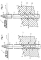
Figure 1 is partial cutaway side view of a perforating system in a wellbore not aligned with a formation dip angle. -
Figure 2 is side cutaway views of a perforating system aligned with a formation dip angle. -
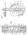
Figure 3 is a partial cutaway view of a gun tube having shaped charges. -
Figure 4 is a partial cutaway view of a wellbore and a surrounding formation with a zone of maximum stress. -
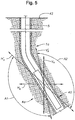
Figure 5 is a partial cutaway view of a perforating gun in a deviated wellbore. - While the invention will be described in connection with the preferred embodiments, it will be understood that it is not intended to limit the invention to that embodiment. On the contrary, it the scope of the invention is only limited according to the wording of the appended claims.
- The present invention will now be described more fully hereinafter with reference to the accompanying drawings in which embodiments of the invention are shown. This invention may, however, be embodied in many different forms and should not be construed as limited to the illustrated embodiments set forth herein; rather, these embodiments are provided so that this disclosure will be thorough and complete, and will fully convey the scope of the invention to those skilled in the art. Like numbers refer to like elements throughout. For the convenience in referring to the accompanying figures, directional terms are used for reference and illustration only. For example, the directional terms such as "upper", "lower", "above", "below", and the like are being used to illustrate a relational location. In the drawings and specification, there have been disclosed illustrative embodiments of the invention and, although specific terms are employed, they are used in a generic and descriptive sense only and not for the purpose of limitation. Accordingly, the invention is therefore to be limited only by the scope of the appended claims.
- With reference again to
Figure 1 thesubterranean formations 2 intersected by thewellbore 1 comprise a series of individual and distinct layers orformations 14.Boundary lines 16 are provided betweenadjacent formations 14 illustrating a border thereby defining the contour of theformations 14. Eachindividual formation 14 is defined as a body of subterranean strata, such as rock, comprising predominantly a single type or types of composition. For example, theformation 14 could comprise a type or types of rock having relatively consistent properties throughout thatformation 14. Examples of characteristics include permeability, density, porosity, resistivity, saturation, dip angle, stress, and combinations thereof. Optionally, aformation 14 may be comprised of low density material other than rock, such as sand, sediment, sedimentary rock, stratum, or sandstone. For the purposes of discussion herein, theformation 14 can be any stratigraphic unit, including a bed, wherein the beds are distinguishable from one another. Thus theformation 14 includes subterranean layers that are distinguishable from adjacent layers and can have thicknesses measurable in tenths of inches (0.1 inch = 2.54mm) and up to hundreds of feet (100ft = 30.5m). - The
formations 14 andboundaries 16 as illustrated are oriented generally oblique to the axis Ax of thewellbore 1;perforations 10 are shown formed through thewellbore 1 and into the formation may cross one ormore boundary lines 16. Theseperforations 10 that intersect one ormore boundary lines 16 may pass through adjacent strata with different and distinctive properties, thereby affecting the permeability from the strata into theperforation 10. - The method and apparatus disclosed herein includes a manner of perforating with respect to a subterranean formation characteristic. The formation characteristics include formation bedding, formation dip angles, directions of constant stress, including a direction of maximum stress, and isotropic zones such as zones of constant density, porosity, permeability, saturation, and the like. The step of perforating thus includes aiming shaped charges with respect to a line(s) or plane(s) defining the formation characteristic. Aiming may include aligning shaped charges with a formation characteristic, or at a desired angle from a formation characteristic. A plane of maximum stress is defined herein as a plane in which the formation stress exceeds that in an adjacent formation(s). The direction of maximum stress denotes the plane's general trajectory along a line within the formation.
-
Figure 2 provides a side partial cross-sectional view of aperforating system 4a disposed in awellbore 1. The perforatingsystem 4a includes a perforatinggun 6a having shapedcharges 8 aimed with the intent of forming ajet 12a that dodges boundary lines 16. Forming a perforatingjet 12a that avoids the boundary lines 16 createsperforations 10a lying within a singleidentifiable formation 14 and thus can also be within a single formation characteristic. Moreover, the shapedcharge 8 can be aimed so itsjet 12a is aligned with theformation 14. One example of alignment comprises aperforation 10a parallel with one or both of theboundary lines 16 lying adjacent to theparticular formation 14. - In one method of forming the
perforation 10a ofFigure 2 , the shapedcharge 8 is aimed to form ajet 12a largely parallel with theformation 14 dip angle. The dip angle may be defined as the angle at which theformation 14 and/orboundary line 16 lies relative to the axis Ax of thewellbore 1. This is sometimes also referred to as the dip of the formation. Perforating into theformation 14 at its dip angle aligns theperforation 10a to the optimal permeability of the reservoir from which hydrocarbons are to be produced. This results in an enhanced and increased flow of hydrocarbons through theperforations 10a and into thewellbore 10a for production of the hydrocarbons. - Optionally, a gyroscope (not shown) can be included with the perforating
system 4a to provide orientation control within thewellbore 1. It should be pointed out that the perforatingsystem 4a ofFigure 2 is not limited to a single gun body, but can include multiple gun bodies strung together adjacently as part of a larger string. Other downhole tools may also be provided in the tool string. Additionally, the perforating method described herein is not limited to a vertical wellbore, but can be in deviated as well as horizontal wellbores. As such, the perforatingsystem 4a may be disposed on wire line as well as any type of tubing, including coiled tubing and a tractor device. - An embodiment in accordance with the invention is provided in side view in
Figure 3 illustrating shapedcharges 8a statically affixed within agun body 6b at an angle oblique to the gun body axis Ax1. The shapedcharges 8a are disposed in a charge tube that is cylindrical and machined to hold thecharges 8a pointing at a desired attitude relative to the gun body axis Ax1. This orientation angle can formperforations 10a aligned with the dip angle of theformation 14. Thecharge tube 18 in this embodiment is longitudinally split into two or more parts (20, 22) havingend fittings 32 at each end to allow the two pieces (20, 22) to be secured at different longitudinal positions with respect to one another. The shapedcharge 8a ends are shown engaged with holes (24, 25, 26, 27) formed through thecharge tube 18 body. When the shapedcharge 8a ends are engaged in the holes (24, 25, 26, 27) selective longitudinal placement of thecharge tube 18 parts (20, 22) in turn angles the shape charges 8a oblique to the axis Ax1. This shifting angularly cants thecharges 8a for a desired alignment to be shot by thecharges 8a. The angle of the shapedcharge 8a can be controlled and selected by adding drilled and tapholes 30 formed to receive screws orbolts 31 in theend fittings 32. -
Figure 4 provides a partial cross sectional view of an example of perforating with respect to a formation characteristic. Here aperforating system 4b is disposed in awellbore 1. Illustrated arejets 12b forming perforations 10b in a reservoir 36 surrounding thewellbore 1. Thejets 12b emanate fromshaped charges 8b in a perforatinggun 6b. A direction ofmaximum stress 34 in the reservoir 36 is shown intersecting thewellbore 1. In the example, the direction ofmaximum stress 34 is generally oblique to the wellbore axis Ax. The shapedcharges 8b have been oriented and/or aligned within the perforatinggun 6b so thejets 12b are either substantially aligned with the direction ofmaximum stress 34 or extend generally parallel to thedirection 34. Optionally the shot phasing on thegun 6b may be at 0° and 180°. For example, the shapedcharges 8b at either 0° or 180° may be aligned with the plane and oriented to form aperforation 10b in theplane 34 coincident with the azimuth radial position where the angle between thedirection 34 and the wellbore axis Ax is at a minimum. Using the embodiment ofFigure 4 as an example, if the 0° phased shot is directed azimuthally as described above and angled upward, the shot at 180° phasing would also be aligned in the plane and directed downward. -
Figure 5 is a cross sectional view of an embodiment of aperforating system 4a in accordance with the present disclosure disposed in a deviatedwellbore 1a. The perforatinggun 6a is disposed onwireline 5 in the deviated portion of thewellbore 1a. A coordinate axis VA and HA are provided that represent potential shot direction. VA is largely parallel with vertical axis atsurface 42 and HA is largely parallel with horizontal axis atsurface 42. Also provided is a dashed axis VA' and HA' these lines graphically illustrate ranges of shot angles (A1, A2) possible with a perforating device, such as an angled perforating system as described herein. A1 and A2 are greater than 90°, and may be equal in some instances. Thus implementation of the angled shaped charges provides for shot angles that exceed vertical and horizontal alignments.
Claims (5)
- A method of perforating a wellbore (1) that intersects a formation (2) having adjacent first and second subterranean layers (14) and a boundary (16) separating the first and second layers, the method comprising:identifying the boundary (16);disposing a perforating gun (6; 6a) in the wellbore (1), the perforating gun (6; 6a) comprising an annular gun body (66), a charge tube (18) inserted within the gun body and a shaped charge (8-8a) held in the charge tube at an angle oblique to a gun body axis (AX1), wherein the charge tube (18) is longitudinally split into two parts (20,22) having end fittings (32) at each end to allow the two parts to be secured at different longitudinal positions with respect to one another, wherein ends of the shaped charge are engaged with holes (24,25,26,27) formed through a body of the charge tube, wherein selective longitudinal placement of the charge tube parts (20,22) in turn angles the shaped charge (8a) oblique to the gun body axis (AX1);orienting the shaped charge (8; 8a) in a direction that avoids the boundary (16); anddetonating the shaped charge (8; 8a) to provide a perforating jet (12a) directed into the first layer along a path that avoids the boundary (16).
- The method as claimed in claim 1, wherein the boundary (16) intersects the wellbore (1) at an oblique angle and directing the perforating jet (12a) comprises orienting the perforating jet azimuthally and at an oblique angle to the axis of the perforating gun (6; 6a).
- The method as claimed in claim 1 or 2, further comprising directing another perforating jet (12b) into the formation (14) along a path that avoids the boundary (16).
- The method as claimed in any of claims 1 to 3, wherein the formation (14) includes a third subterranean layer adjacent the second layer and an additional boundary (16) between the second and third layers.
- The method as claimed in any preceding claim, further comprising detecting a plane of maximum stress in the formation (14) and directing a first perforating jet (12a) into the plane of maximum stress.
Applications Claiming Priority (2)
| Application Number | Priority Date | Filing Date | Title |
|---|---|---|---|
| US3959508P | 2008-03-26 | 2008-03-26 | |
| PCT/US2009/038595 WO2009120980A2 (en) | 2008-03-26 | 2009-03-27 | Selectively angled perforating |
Publications (3)
| Publication Number | Publication Date |
|---|---|
| EP2268893A2 EP2268893A2 (en) | 2011-01-05 |
| EP2268893A4 EP2268893A4 (en) | 2014-05-28 |
| EP2268893B1 true EP2268893B1 (en) | 2018-11-14 |
Family
ID=41114779
Family Applications (1)
| Application Number | Title | Priority Date | Filing Date |
|---|---|---|---|
| EP09724850.4A Not-in-force EP2268893B1 (en) | 2008-03-26 | 2009-03-27 | Selectively angled perforating |
Country Status (6)
| Country | Link |
|---|---|
| US (1) | US8127848B2 (en) |
| EP (1) | EP2268893B1 (en) |
| CA (1) | CA2718439C (en) |
| DK (1) | DK2268893T3 (en) |
| GB (1) | GB2470697B (en) |
| WO (1) | WO2009120980A2 (en) |
Cited By (4)
| Publication number | Priority date | Publication date | Assignee | Title |
|---|---|---|---|---|
| US11834934B2 (en) | 2019-05-16 | 2023-12-05 | Schlumberger Technology Corporation | Modular perforation tool |
| USD1016958S1 (en) | 2020-09-11 | 2024-03-05 | Schlumberger Technology Corporation | Shaped charge frame |
| US12098623B2 (en) | 2020-11-13 | 2024-09-24 | Schlumberger Technology Corporation | Oriented-perforation tool |
| US12252964B2 (en) | 2020-11-13 | 2025-03-18 | Schlumberger Technology Corporation | Large shaped charge perforation tool |
Families Citing this family (36)
| Publication number | Priority date | Publication date | Assignee | Title |
|---|---|---|---|---|
| EP2213832A3 (en) * | 2009-01-29 | 2011-10-26 | Linde Aktiengesellschaft | Method for injecting a fluid |
| US9376902B2 (en) * | 2011-08-16 | 2016-06-28 | Schlumberger Technology Corporation | Method to optimize perforations for hydraulic fracturing in anisotropic earth formations |
| US8851191B2 (en) | 2011-10-18 | 2014-10-07 | Baker Hughes Incorporated | Selectively fired high pressure high temperature back-off tool |
| RU2493357C1 (en) * | 2012-04-12 | 2013-09-20 | Открытое акционерное общество "Всероссийский научно-исследовательский и проектно-конструкторский институт по использованию энергии взрыва в геофизике" (ОАО "ВНИПИвзрывгеофизика") | Method for well completion by cumulative charges |
| US9145763B1 (en) * | 2012-05-15 | 2015-09-29 | Joseph A. Sites, Jr. | Perforation gun with angled shaped charges |
| CN102953712A (en) * | 2012-11-01 | 2013-03-06 | 关俊华 | Upper tilting perforation diversion anchored fracturing umbrella ditch gravity oil production method |
| WO2014140752A1 (en) * | 2013-03-15 | 2014-09-18 | Ormat Technologies Inc. | Method for selecting the location of a simulating geothermal well |
| US9702680B2 (en) | 2013-07-18 | 2017-07-11 | Dynaenergetics Gmbh & Co. Kg | Perforation gun components and system |
| WO2015120181A1 (en) * | 2014-02-05 | 2015-08-13 | Thru Tubing Solutions, Inc. | Downhole perforator gun bypass tool |
| US9845666B2 (en) | 2014-02-08 | 2017-12-19 | Geodynamics, Inc. | Limited entry phased perforating gun system and method |
| US9562421B2 (en) * | 2014-02-08 | 2017-02-07 | Geodynamics, Inc. | Limited entry phased perforating gun system and method |
| US9038521B1 (en) * | 2014-02-08 | 2015-05-26 | Geodynamics, Inc. | Apparatus for creating and customizing intersecting jets with oilfield shaped charges |
| WO2016007481A1 (en) | 2014-07-07 | 2016-01-14 | Saudi Arabian Oil Company | Method to create connectivity between wellbore and formation |
| US10138713B2 (en) | 2014-09-08 | 2018-11-27 | Exxonmobil Upstream Research Company | Autonomous wellbore devices with orientation-regulating structures and systems and methods including the same |
| CN104278976A (en) * | 2014-10-11 | 2015-01-14 | 大庆红祥寓科技有限公司 | Perforator with directions and perforation angles determined inside |
| WO2016100762A1 (en) | 2014-12-19 | 2016-06-23 | Schlumberger Canada Limited | Workflows to address localized stress regime heterogeneity to enable hydraulic fracturing |
| MX384288B (en) | 2015-06-05 | 2025-03-14 | Geodynamics Inc | DRILLING GUN SYSTEM AND METHOD IN LIMITED ENTRY PHASE. |
| GB201513269D0 (en) * | 2015-07-28 | 2015-09-09 | Delphian Ballistics Ltd | Perforating gun assembly and methods of use |
| WO2017049262A1 (en) * | 2015-09-18 | 2017-03-23 | Schlumberger Technology Corporation | Systems and methods for performing hydraulic fracturing in vertically heterogenous regions |
| US10174595B2 (en) * | 2015-10-23 | 2019-01-08 | G&H Diversified Manufacturing Lp | Perforating tool |
| US11414965B2 (en) * | 2018-02-27 | 2022-08-16 | Schlumberger Technology Corporation | Rotating loading tube and angled shaped charges for oriented perforating |
| US10669821B2 (en) * | 2018-04-25 | 2020-06-02 | G&H Diversified Manufacturing Lp | Charge tube assembly |
| US10458213B1 (en) | 2018-07-17 | 2019-10-29 | Dynaenergetics Gmbh & Co. Kg | Positioning device for shaped charges in a perforating gun module |
| GB2598475B (en) | 2019-04-24 | 2022-12-14 | Halliburton Energy Services Inc | Apparatus and method for behind casing washout |
| US12385369B2 (en) | 2019-06-14 | 2025-08-12 | DynaEngergetics Europe GmbH | Perforating gun assembly with rotating shaped charge holder |
| US11480038B2 (en) | 2019-12-17 | 2022-10-25 | DynaEnergetics Europe GmbH | Modular perforating gun system |
| US11293271B1 (en) | 2020-10-28 | 2022-04-05 | Halliburton Energy Services, Inc. | Low-profile adjustable fastener for charge orientation of a downhole perforating tool |
| CN112593903A (en) * | 2020-12-14 | 2021-04-02 | 大庆石油管理局有限公司 | Fixed-firing-angle inner blind hole perforating gun |
| US11732556B2 (en) | 2021-03-03 | 2023-08-22 | DynaEnergetics Europe GmbH | Orienting perforation gun assembly |
| US12241361B2 (en) | 2021-08-24 | 2025-03-04 | Saudi Arabian Oil Company | Method and system to determine optimal perforation orientation for hydraulic fracturing slant wells |
| US12428938B2 (en) * | 2022-01-06 | 2025-09-30 | Halliburton Energy Services, Inc. | Perforating gun with self-orienting perforating charges |
| US12398628B2 (en) * | 2023-03-27 | 2025-08-26 | Halliburton Energy Services, Inc. | Using opposing charges to balance force |
| US12577859B2 (en) | 2023-05-30 | 2026-03-17 | Schlumberger Technology Corporation | Interventions to boost well performance in geothermal systems |
| US20240401450A1 (en) * | 2023-05-30 | 2024-12-05 | Schlumberger Technology Corporation | Boosting well performance in geothermal systems |
| US12669020B2 (en) | 2023-05-30 | 2026-06-30 | Schlumberger Technology Corporation | Coiled tubing systems and methods for geothermal wells |
| US12449163B2 (en) | 2023-10-02 | 2025-10-21 | Schlumberger Technology Corporation | Boosting well performance in geothermal systems |
Family Cites Families (24)
| Publication number | Priority date | Publication date | Assignee | Title |
|---|---|---|---|---|
| NL23055C (en) * | 1928-12-28 | 1930-05-15 | ||
| US2974589A (en) * | 1957-06-03 | 1961-03-14 | Du Pont | Jet perforators |
| US3062294A (en) * | 1959-11-13 | 1962-11-06 | Gulf Research Development Co | Apparatus for fracturing a formation |
| US3163112A (en) * | 1962-08-02 | 1964-12-29 | Jersey Prod Res Co | Well preforating |
| US3704749A (en) * | 1971-05-06 | 1972-12-05 | Nl Industries Inc | Method and apparatus for tool orientation in a bore hole |
| US4074756A (en) * | 1977-01-17 | 1978-02-21 | Exxon Production Research Company | Apparatus and method for well repair operations |
| US4105073A (en) * | 1977-09-26 | 1978-08-08 | Brieger Emmet F | Tubing conveyed sand consolidating method |
| US4552234A (en) * | 1981-07-13 | 1985-11-12 | Halliburton Company | Spiral gun apparatus |
| US4442891A (en) * | 1982-03-01 | 1984-04-17 | Insituform International N.V. | Cutters |
| US4756371A (en) * | 1986-12-15 | 1988-07-12 | Brieger Emmet F | Perforation apparatus and method |
| US4961365A (en) * | 1988-07-28 | 1990-10-09 | Schlumberger Technology Corporation | Perforating gun with rotating charges including a mechanical link retaining mechanism |
| US5040619A (en) * | 1990-04-12 | 1991-08-20 | Halliburton Logging Services, Inc. | Wireline supported perforating gun enabling oriented perforations |
| US5095801A (en) * | 1991-03-08 | 1992-03-17 | Schlumberger Technology Corporation | Pivot gun having charges which slidingly engage a stationary detonating cord and apparatus for deploying the charges |
| US5318123A (en) * | 1992-06-11 | 1994-06-07 | Halliburton Company | Method for optimizing hydraulic fracturing through control of perforation orientation |
| US5964294A (en) * | 1996-12-04 | 1999-10-12 | Schlumberger Technology Corporation | Apparatus and method for orienting a downhole tool in a horizontal or deviated well |
| US5765642A (en) * | 1996-12-23 | 1998-06-16 | Halliburton Energy Services, Inc. | Subterranean formation fracturing methods |
| US6397947B1 (en) * | 1999-05-04 | 2002-06-04 | Schlumberger Technology Corporation | Optimizing charge phasing of a perforating gun |
| US6401818B1 (en) | 1999-05-27 | 2002-06-11 | Schlumberger Technology Corporation | Wellbore perforation method and apparatus |
| US6679327B2 (en) * | 2001-11-30 | 2004-01-20 | Baker Hughes, Inc. | Internal oriented perforating system and method |
| US7172023B2 (en) * | 2004-03-04 | 2007-02-06 | Delphian Technologies, Ltd. | Perforating gun assembly and method for enhancing perforation depth |
| US7303017B2 (en) * | 2004-03-04 | 2007-12-04 | Delphian Technologies, Ltd. | Perforating gun assembly and method for creating perforation cavities |
| US7159657B2 (en) * | 2004-03-24 | 2007-01-09 | Schlumberger Technology Corporation | Shaped charge loading tube for perforating gun |
| US20050247447A1 (en) * | 2004-05-10 | 2005-11-10 | Spring Roger L | Angled perforating device for well completions |
| US20060118303A1 (en) * | 2004-12-06 | 2006-06-08 | Halliburton Energy Services, Inc. | Well perforating for increased production |
-
2009
- 2009-03-26 US US12/412,101 patent/US8127848B2/en not_active Expired - Fee Related
- 2009-03-27 EP EP09724850.4A patent/EP2268893B1/en not_active Not-in-force
- 2009-03-27 GB GB1016055.4A patent/GB2470697B/en active Active
- 2009-03-27 DK DK09724850.4T patent/DK2268893T3/en active
- 2009-03-27 CA CA2718439A patent/CA2718439C/en not_active Expired - Fee Related
- 2009-03-27 WO PCT/US2009/038595 patent/WO2009120980A2/en not_active Ceased
Non-Patent Citations (1)
| Title |
|---|
| None * |
Cited By (6)
| Publication number | Priority date | Publication date | Assignee | Title |
|---|---|---|---|---|
| US11834934B2 (en) | 2019-05-16 | 2023-12-05 | Schlumberger Technology Corporation | Modular perforation tool |
| US12398626B2 (en) | 2019-05-16 | 2025-08-26 | Schlumberger Technology Corporation | Modular perforation tool |
| USD1016958S1 (en) | 2020-09-11 | 2024-03-05 | Schlumberger Technology Corporation | Shaped charge frame |
| US12098623B2 (en) | 2020-11-13 | 2024-09-24 | Schlumberger Technology Corporation | Oriented-perforation tool |
| US12252964B2 (en) | 2020-11-13 | 2025-03-18 | Schlumberger Technology Corporation | Large shaped charge perforation tool |
| US12529293B2 (en) | 2020-11-13 | 2026-01-20 | Schlumberger Technology Corporation | Oriented-perforation tool |
Also Published As
| Publication number | Publication date |
|---|---|
| CA2718439A1 (en) | 2009-10-01 |
| CA2718439C (en) | 2014-01-07 |
| EP2268893A2 (en) | 2011-01-05 |
| GB201016055D0 (en) | 2010-11-10 |
| WO2009120980A3 (en) | 2009-11-19 |
| GB2470697A (en) | 2010-12-01 |
| US20090242198A1 (en) | 2009-10-01 |
| US8127848B2 (en) | 2012-03-06 |
| WO2009120980A2 (en) | 2009-10-01 |
| GB2470697B (en) | 2012-12-05 |
| DK2268893T3 (en) | 2019-01-02 |
| EP2268893A4 (en) | 2014-05-28 |
Similar Documents
| Publication | Publication Date | Title |
|---|---|---|
| CA2718439C (en) | Selectively angled perforating | |
| US9845666B2 (en) | Limited entry phased perforating gun system and method | |
| US10422204B2 (en) | System and method for perforating a wellbore | |
| US9562421B2 (en) | Limited entry phased perforating gun system and method | |
| US7604055B2 (en) | Completion method with telescoping perforation and fracturing tool | |
| US10208573B2 (en) | Perforating gun with integrated retaining system | |
| US8919443B2 (en) | Method for generating discrete fracture initiation sites and propagating dominant planar fractures therefrom | |
| US9238956B2 (en) | Perforating gun apparatus for generating perforations having variable penetration profiles | |
| US8126646B2 (en) | Perforating optimized for stress gradients around wellbore | |
| GB2522494A (en) | Perforating gun assembly and method of forming wellbore perfortions | |
| US8424606B2 (en) | Method and apparatus for perforating with reduced debris in wellbore | |
| US20230212927A1 (en) | Perforating Gun With Self-Orienting Perforating Charges | |
| AU2018282890B2 (en) | Limited penetration perforating methods for oilfield applications | |
| EP3101221B1 (en) | Limited entry phased perforating gun system and method | |
| CA2974013C (en) | Limited entry phased perforating gun system and method | |
| US6401818B1 (en) | Wellbore perforation method and apparatus | |
| US11933148B2 (en) | Tri-angled liner with jet shaper | |
| US20250237122A1 (en) | Slot Perforating Assembly | |
| US20240328287A1 (en) | Using Opposing Charges To Balance Force | |
| US10161724B2 (en) | Shaped-charge liner with fold around opening | |
| CN112105793A (en) | Multi-stage single-point short gun perforating device for oil field application |
Legal Events
| Date | Code | Title | Description |
|---|---|---|---|
| PUAI | Public reference made under article 153(3) epc to a published international application that has entered the european phase |
Free format text: ORIGINAL CODE: 0009012 |
|
| 17P | Request for examination filed |
Effective date: 20100920 |
|
| AK | Designated contracting states |
Kind code of ref document: A2 Designated state(s): AT BE BG CH CY CZ DE DK EE ES FI FR GB GR HR HU IE IS IT LI LT LU LV MC MK MT NL NO PL PT RO SE SI SK TR |
|
| AX | Request for extension of the european patent |
Extension state: AL BA RS |
|
| DAX | Request for extension of the european patent (deleted) | ||
| A4 | Supplementary search report drawn up and despatched |
Effective date: 20140430 |
|
| RIC1 | Information provided on ipc code assigned before grant |
Ipc: E21B 43/119 20060101ALI20140424BHEP Ipc: E21B 43/116 20060101AFI20140424BHEP |
|
| STAA | Information on the status of an ep patent application or granted ep patent |
Free format text: STATUS: EXAMINATION IS IN PROGRESS |
|
| 17Q | First examination report despatched |
Effective date: 20170412 |
|
| GRAP | Despatch of communication of intention to grant a patent |
Free format text: ORIGINAL CODE: EPIDOSNIGR1 |
|
| STAA | Information on the status of an ep patent application or granted ep patent |
Free format text: STATUS: GRANT OF PATENT IS INTENDED |
|
| INTG | Intention to grant announced |
Effective date: 20180216 |
|
| GRAS | Grant fee paid |
Free format text: ORIGINAL CODE: EPIDOSNIGR3 |
|
| RAP1 | Party data changed (applicant data changed or rights of an application transferred) |
Owner name: BAKER HUGHES, A GE COMPANY, LLC |
|
| GRAA | (expected) grant |
Free format text: ORIGINAL CODE: 0009210 |
|
| STAA | Information on the status of an ep patent application or granted ep patent |
Free format text: STATUS: THE PATENT HAS BEEN GRANTED |
|
| AK | Designated contracting states |
Kind code of ref document: B1 Designated state(s): AT BE BG CH CY CZ DE DK EE ES FI FR GB GR HR HU IE IS IT LI LT LU LV MC MK MT NL NO PL PT RO SE SI SK TR |
|
| REG | Reference to a national code |
Ref country code: GB Ref legal event code: FG4D |
|
| REG | Reference to a national code |
Ref country code: CH Ref legal event code: EP Ref country code: AT Ref legal event code: REF Ref document number: 1065043 Country of ref document: AT Kind code of ref document: T Effective date: 20181115 |
|
| REG | Reference to a national code |
Ref country code: DE Ref legal event code: R096 Ref document number: 602009055625 Country of ref document: DE |
|
| REG | Reference to a national code |
Ref country code: IE Ref legal event code: FG4D |
|
| REG | Reference to a national code |
Ref country code: DK Ref legal event code: T3 Effective date: 20181217 |
|
| REG | Reference to a national code |
Ref country code: NO Ref legal event code: T2 Effective date: 20181114 |
|
| REG | Reference to a national code |
Ref country code: NL Ref legal event code: MP Effective date: 20181114 |
|
| REG | Reference to a national code |
Ref country code: LT Ref legal event code: MG4D |
|
| REG | Reference to a national code |
Ref country code: AT Ref legal event code: MK05 Ref document number: 1065043 Country of ref document: AT Kind code of ref document: T Effective date: 20181114 |
|
| PG25 | Lapsed in a contracting state [announced via postgrant information from national office to epo] |
Ref country code: HR Free format text: LAPSE BECAUSE OF FAILURE TO SUBMIT A TRANSLATION OF THE DESCRIPTION OR TO PAY THE FEE WITHIN THE PRESCRIBED TIME-LIMIT Effective date: 20181114 Ref country code: LT Free format text: LAPSE BECAUSE OF FAILURE TO SUBMIT A TRANSLATION OF THE DESCRIPTION OR TO PAY THE FEE WITHIN THE PRESCRIBED TIME-LIMIT Effective date: 20181114 Ref country code: AT Free format text: LAPSE BECAUSE OF FAILURE TO SUBMIT A TRANSLATION OF THE DESCRIPTION OR TO PAY THE FEE WITHIN THE PRESCRIBED TIME-LIMIT Effective date: 20181114 Ref country code: LV Free format text: LAPSE BECAUSE OF FAILURE TO SUBMIT A TRANSLATION OF THE DESCRIPTION OR TO PAY THE FEE WITHIN THE PRESCRIBED TIME-LIMIT Effective date: 20181114 Ref country code: FI Free format text: LAPSE BECAUSE OF FAILURE TO SUBMIT A TRANSLATION OF THE DESCRIPTION OR TO PAY THE FEE WITHIN THE PRESCRIBED TIME-LIMIT Effective date: 20181114 Ref country code: IS Free format text: LAPSE BECAUSE OF FAILURE TO SUBMIT A TRANSLATION OF THE DESCRIPTION OR TO PAY THE FEE WITHIN THE PRESCRIBED TIME-LIMIT Effective date: 20190314 Ref country code: ES Free format text: LAPSE BECAUSE OF FAILURE TO SUBMIT A TRANSLATION OF THE DESCRIPTION OR TO PAY THE FEE WITHIN THE PRESCRIBED TIME-LIMIT Effective date: 20181114 Ref country code: BG Free format text: LAPSE BECAUSE OF FAILURE TO SUBMIT A TRANSLATION OF THE DESCRIPTION OR TO PAY THE FEE WITHIN THE PRESCRIBED TIME-LIMIT Effective date: 20190214 |
|
| PGFP | Annual fee paid to national office [announced via postgrant information from national office to epo] |
Ref country code: SE Payment date: 20190320 Year of fee payment: 7 |
|
| PG25 | Lapsed in a contracting state [announced via postgrant information from national office to epo] |
Ref country code: GR Free format text: LAPSE BECAUSE OF FAILURE TO SUBMIT A TRANSLATION OF THE DESCRIPTION OR TO PAY THE FEE WITHIN THE PRESCRIBED TIME-LIMIT Effective date: 20190215 Ref country code: NL Free format text: LAPSE BECAUSE OF FAILURE TO SUBMIT A TRANSLATION OF THE DESCRIPTION OR TO PAY THE FEE WITHIN THE PRESCRIBED TIME-LIMIT Effective date: 20181114 Ref country code: PT Free format text: LAPSE BECAUSE OF FAILURE TO SUBMIT A TRANSLATION OF THE DESCRIPTION OR TO PAY THE FEE WITHIN THE PRESCRIBED TIME-LIMIT Effective date: 20190314 Ref country code: SE Free format text: LAPSE BECAUSE OF FAILURE TO SUBMIT A TRANSLATION OF THE DESCRIPTION OR TO PAY THE FEE WITHIN THE PRESCRIBED TIME-LIMIT Effective date: 20181114 |
|
| PG25 | Lapsed in a contracting state [announced via postgrant information from national office to epo] |
Ref country code: PL Free format text: LAPSE BECAUSE OF FAILURE TO SUBMIT A TRANSLATION OF THE DESCRIPTION OR TO PAY THE FEE WITHIN THE PRESCRIBED TIME-LIMIT Effective date: 20181114 Ref country code: CZ Free format text: LAPSE BECAUSE OF FAILURE TO SUBMIT A TRANSLATION OF THE DESCRIPTION OR TO PAY THE FEE WITHIN THE PRESCRIBED TIME-LIMIT Effective date: 20181114 |
|
| REG | Reference to a national code |
Ref country code: DE Ref legal event code: R097 Ref document number: 602009055625 Country of ref document: DE |
|
| PG25 | Lapsed in a contracting state [announced via postgrant information from national office to epo] |
Ref country code: RO Free format text: LAPSE BECAUSE OF FAILURE TO SUBMIT A TRANSLATION OF THE DESCRIPTION OR TO PAY THE FEE WITHIN THE PRESCRIBED TIME-LIMIT Effective date: 20181114 Ref country code: EE Free format text: LAPSE BECAUSE OF FAILURE TO SUBMIT A TRANSLATION OF THE DESCRIPTION OR TO PAY THE FEE WITHIN THE PRESCRIBED TIME-LIMIT Effective date: 20181114 Ref country code: SK Free format text: LAPSE BECAUSE OF FAILURE TO SUBMIT A TRANSLATION OF THE DESCRIPTION OR TO PAY THE FEE WITHIN THE PRESCRIBED TIME-LIMIT Effective date: 20181114 |
|
| PLBE | No opposition filed within time limit |
Free format text: ORIGINAL CODE: 0009261 |
|
| STAA | Information on the status of an ep patent application or granted ep patent |
Free format text: STATUS: NO OPPOSITION FILED WITHIN TIME LIMIT |
|
| 26N | No opposition filed |
Effective date: 20190815 |
|
| PG25 | Lapsed in a contracting state [announced via postgrant information from national office to epo] |
Ref country code: MC Free format text: LAPSE BECAUSE OF FAILURE TO SUBMIT A TRANSLATION OF THE DESCRIPTION OR TO PAY THE FEE WITHIN THE PRESCRIBED TIME-LIMIT Effective date: 20181114 Ref country code: SI Free format text: LAPSE BECAUSE OF FAILURE TO SUBMIT A TRANSLATION OF THE DESCRIPTION OR TO PAY THE FEE WITHIN THE PRESCRIBED TIME-LIMIT Effective date: 20181114 |
|
| REG | Reference to a national code |
Ref country code: CH Ref legal event code: PL |
|
| PG25 | Lapsed in a contracting state [announced via postgrant information from national office to epo] |
Ref country code: LU Free format text: LAPSE BECAUSE OF NON-PAYMENT OF DUE FEES Effective date: 20190327 |
|
| REG | Reference to a national code |
Ref country code: BE Ref legal event code: MM Effective date: 20190331 |
|
| PG25 | Lapsed in a contracting state [announced via postgrant information from national office to epo] |
Ref country code: LI Free format text: LAPSE BECAUSE OF NON-PAYMENT OF DUE FEES Effective date: 20190331 Ref country code: CH Free format text: LAPSE BECAUSE OF NON-PAYMENT OF DUE FEES Effective date: 20190331 Ref country code: IE Free format text: LAPSE BECAUSE OF NON-PAYMENT OF DUE FEES Effective date: 20190327 |
|
| PG25 | Lapsed in a contracting state [announced via postgrant information from national office to epo] |
Ref country code: BE Free format text: LAPSE BECAUSE OF NON-PAYMENT OF DUE FEES Effective date: 20190331 |
|
| PG25 | Lapsed in a contracting state [announced via postgrant information from national office to epo] |
Ref country code: TR Free format text: LAPSE BECAUSE OF FAILURE TO SUBMIT A TRANSLATION OF THE DESCRIPTION OR TO PAY THE FEE WITHIN THE PRESCRIBED TIME-LIMIT Effective date: 20181114 |
|
| PGFP | Annual fee paid to national office [announced via postgrant information from national office to epo] |
Ref country code: IT Payment date: 20200218 Year of fee payment: 12 |
|
| PG25 | Lapsed in a contracting state [announced via postgrant information from national office to epo] |
Ref country code: MT Free format text: LAPSE BECAUSE OF NON-PAYMENT OF DUE FEES Effective date: 20190327 |
|
| PGFP | Annual fee paid to national office [announced via postgrant information from national office to epo] |
Ref country code: FR Payment date: 20200220 Year of fee payment: 12 |
|
| GBPC | Gb: european patent ceased through non-payment of renewal fee |
Effective date: 20200327 |
|
| PG25 | Lapsed in a contracting state [announced via postgrant information from national office to epo] |
Ref country code: GB Free format text: LAPSE BECAUSE OF NON-PAYMENT OF DUE FEES Effective date: 20200327 |
|
| PG25 | Lapsed in a contracting state [announced via postgrant information from national office to epo] |
Ref country code: CY Free format text: LAPSE BECAUSE OF FAILURE TO SUBMIT A TRANSLATION OF THE DESCRIPTION OR TO PAY THE FEE WITHIN THE PRESCRIBED TIME-LIMIT Effective date: 20181114 |
|
| PG25 | Lapsed in a contracting state [announced via postgrant information from national office to epo] |
Ref country code: HU Free format text: LAPSE BECAUSE OF FAILURE TO SUBMIT A TRANSLATION OF THE DESCRIPTION OR TO PAY THE FEE WITHIN THE PRESCRIBED TIME-LIMIT; INVALID AB INITIO Effective date: 20090327 |
|
| PG25 | Lapsed in a contracting state [announced via postgrant information from national office to epo] |
Ref country code: FR Free format text: LAPSE BECAUSE OF NON-PAYMENT OF DUE FEES Effective date: 20210331 |
|
| PG25 | Lapsed in a contracting state [announced via postgrant information from national office to epo] |
Ref country code: IT Free format text: LAPSE BECAUSE OF NON-PAYMENT OF DUE FEES Effective date: 20210327 |
|
| PG25 | Lapsed in a contracting state [announced via postgrant information from national office to epo] |
Ref country code: MK Free format text: LAPSE BECAUSE OF FAILURE TO SUBMIT A TRANSLATION OF THE DESCRIPTION OR TO PAY THE FEE WITHIN THE PRESCRIBED TIME-LIMIT Effective date: 20181114 |
|
| PGFP | Annual fee paid to national office [announced via postgrant information from national office to epo] |
Ref country code: NO Payment date: 20230223 Year of fee payment: 15 Ref country code: DK Payment date: 20230221 Year of fee payment: 15 |
|
| PGFP | Annual fee paid to national office [announced via postgrant information from national office to epo] |
Ref country code: DE Payment date: 20230221 Year of fee payment: 15 |
|
| REG | Reference to a national code |
Ref country code: DE Ref legal event code: R119 Ref document number: 602009055625 Country of ref document: DE |
|
| REG | Reference to a national code |
Ref country code: DK Ref legal event code: EBP Effective date: 20240331 |
|
| PG25 | Lapsed in a contracting state [announced via postgrant information from national office to epo] |
Ref country code: DE Free format text: LAPSE BECAUSE OF NON-PAYMENT OF DUE FEES Effective date: 20241001 |
|
| PG25 | Lapsed in a contracting state [announced via postgrant information from national office to epo] |
Ref country code: NO Free format text: LAPSE BECAUSE OF NON-PAYMENT OF DUE FEES Effective date: 20240331 |
|
| PG25 | Lapsed in a contracting state [announced via postgrant information from national office to epo] |
Ref country code: NO Free format text: LAPSE BECAUSE OF NON-PAYMENT OF DUE FEES Effective date: 20240331 Ref country code: DE Free format text: LAPSE BECAUSE OF NON-PAYMENT OF DUE FEES Effective date: 20241001 |
|
| PG25 | Lapsed in a contracting state [announced via postgrant information from national office to epo] |
Ref country code: DK Free format text: LAPSE BECAUSE OF NON-PAYMENT OF DUE FEES Effective date: 20240331 |