EP2268004A2 - Rundfunkempfänger und Verfahren - Google Patents
Rundfunkempfänger und Verfahren Download PDFInfo
- Publication number
- EP2268004A2 EP2268004A2 EP10275050A EP10275050A EP2268004A2 EP 2268004 A2 EP2268004 A2 EP 2268004A2 EP 10275050 A EP10275050 A EP 10275050A EP 10275050 A EP10275050 A EP 10275050A EP 2268004 A2 EP2268004 A2 EP 2268004A2
- Authority
- EP
- European Patent Office
- Prior art keywords
- physical layer
- data
- circuitry
- common
- layer pipe
- Prior art date
- Legal status (The legal status is an assumption and is not a legal conclusion. Google has not performed a legal analysis and makes no representation as to the accuracy of the status listed.)
- Granted
Links
Images






Classifications
-
- H—ELECTRICITY
- H04—ELECTRIC COMMUNICATION TECHNIQUE
- H04N—PICTORIAL COMMUNICATION, e.g. TELEVISION
- H04N5/00—Details of television systems
- H04N5/44—Receiver circuitry for the reception of television signals according to analogue transmission standards
-
- H—ELECTRICITY
- H04—ELECTRIC COMMUNICATION TECHNIQUE
- H04H—BROADCAST COMMUNICATION
- H04H40/00—Arrangements specially adapted for receiving broadcast information
-
- H—ELECTRICITY
- H04—ELECTRIC COMMUNICATION TECHNIQUE
- H04L—TRANSMISSION OF DIGITAL INFORMATION, e.g. TELEGRAPHIC COMMUNICATION
- H04L5/00—Arrangements affording multiple use of the transmission path
- H04L5/003—Arrangements for allocating sub-channels of the transmission path
-
- H—ELECTRICITY
- H04—ELECTRIC COMMUNICATION TECHNIQUE
- H04N—PICTORIAL COMMUNICATION, e.g. TELEVISION
- H04N21/00—Selective content distribution, e.g. interactive television or video on demand [VOD]
- H04N21/40—Client devices specifically adapted for the reception of or interaction with content, e.g. set-top-box [STB]; Operations thereof
- H04N21/43—Processing of content or additional data, e.g. demultiplexing additional data from a digital video stream; Elementary client operations, e.g. monitoring of home network or synchronising decoder's clock; Client middleware
- H04N21/438—Interfacing the downstream path of the transmission network originating from a server, e.g. retrieving encoded video stream packets from an IP network
- H04N21/4382—Demodulation or channel decoding, e.g. QPSK demodulation
-
- H—ELECTRICITY
- H04—ELECTRIC COMMUNICATION TECHNIQUE
- H04N—PICTORIAL COMMUNICATION, e.g. TELEVISION
- H04N21/00—Selective content distribution, e.g. interactive television or video on demand [VOD]
- H04N21/40—Client devices specifically adapted for the reception of or interaction with content, e.g. set-top-box [STB]; Operations thereof
- H04N21/43—Processing of content or additional data, e.g. demultiplexing additional data from a digital video stream; Elementary client operations, e.g. monitoring of home network or synchronising decoder's clock; Client middleware
- H04N21/438—Interfacing the downstream path of the transmission network originating from a server, e.g. retrieving encoded video stream packets from an IP network
- H04N21/4383—Accessing a communication channel
-
- H—ELECTRICITY
- H04—ELECTRIC COMMUNICATION TECHNIQUE
- H04N—PICTORIAL COMMUNICATION, e.g. TELEVISION
- H04N21/00—Selective content distribution, e.g. interactive television or video on demand [VOD]
- H04N21/60—Network structure or processes for video distribution between server and client or between remote clients; Control signalling between clients, server and network components; Transmission of management data between server and client, e.g. sending from server to client commands for recording incoming content stream; Communication details between server and client
- H04N21/61—Network physical structure; Signal processing
- H04N21/6106—Network physical structure; Signal processing specially adapted to the downstream path of the transmission network
- H04N21/6112—Network physical structure; Signal processing specially adapted to the downstream path of the transmission network involving terrestrial transmission, e.g. DVB-T
-
- H—ELECTRICITY
- H04—ELECTRIC COMMUNICATION TECHNIQUE
- H04N—PICTORIAL COMMUNICATION, e.g. TELEVISION
- H04N5/00—Details of television systems
- H04N5/44—Receiver circuitry for the reception of television signals according to analogue transmission standards
- H04N5/455—Demodulation-circuits
Definitions
- the present invention relates to a broadcast receiver and method for obtaining a selected data stream from a broadcast signal carrying a plurality of data streams.
- the broadcast receiver may be a television receiver.
- DVB-T Digital Video Broadcasting - Terrestrial
- DVB-T2 uses OFDM (orthogonal frequency division multiplex) modulation comprising a large number of sub-carriers transmitted on a symbol-by-symbol basis.
- DVB-T2 includes a number of features which are not included in the DVB-T standard. These include the use of time-interleaved physical layer pipes (PLPs) within the broadcast signal which carry respective data streams each representing one or more services.
- PLPs physical layer pipes
- These physical layer pipes may be considered as channels which are transparent to the method of network delivery, and which in the case of DVB-T2 are Time-Division-Multiplex (TDM) channels carried by specified sub-slices.
- TDM Time-Division-Multiplex
- the physical layer pipes are Frequency Division Multiplex channels.
- Physical layer pipes may also feature as channels in other network delivery schemes, including for example DVB-S2.
- the physical layer pipes provided for by the DVB-T2 standard include data physical layer pipes which carry at least a portion of a respective data stream, and common physical layer pipes which carry a common portion of two or more data streams. Where data is common to two or more data streams, respective data physical layer pipes carry the non-common portions of the data streams, and a common physical layer pipe carries the common portion.
- a common physical layer pipe In order to demodulate a data stream which is carried partly on a data physical layer pipe and partly on a common physical layer pipe, it is necessary to extract both the data physical layer pipe and the common physical layer pipe from the broadcast signal.
- Digital TVs commonly employ an architecture in which an input signal from a receiving antenna first passes through an RF (radio-frequency) tuner, and is then demodulated by demodulator circuitry.
- the demodulated signal is then passed to host circuitry, which decompresses and decodes the signal for output.
- the demodulated signal may then be passed between the demodulator circuitry and the host circuitry in the form of an MPEG (Motion Pictures Expert Group) transport stream.
- the MPEG transport stream may then be decompressed and decoded by the host circuitry.
- the host circuit contains a CPU (Central Processing Unit) which runs host software, the functions of which include controlling the demodulator circuitry to demodulate a selected data stream, and control of the decompression and decoding process of the MPEG transport stream.
- CPU Central Processing Unit
- a broadcast receiver comprising demodulator circuitry, host circuitry and an interface formed between the demodulator circuitry and the host circuitry, the demodulator circuitry being arranged in operation to receive a broadcast signal carrying a plurality of data streams on a respective plurality of data physical layer pipes and one or more common physical layer pipes, each of the data physical layer pipes carrying at least a unique portion of a corresponding one of the data streams, and the common physical layer pipes carrying a common portion of two or more of the plurality of data streams; to identify each of the data physical layer pipes and the common physical layer pipes present in the broadcast signal and to determine an association between the common physical layer pipes and the data physical layer pipes; to store the determined association between the common physical layer pipes and the data physical layer pipes in a data store; and to communicate an identification of each of the data physical layer pipes present in the broadcast signal to the host circuitry via the interface; the host circuitry being arranged in operation to communicate, to the demodulator circuitry via the interface, an identification of a
- the amount of data crossing the interface between the demodulator circuitry and the host circuitry can be reduced. This reduces the level of electrical noise that may be generated by the physical interface, which will in turn reduce interference with the sensitive electronic circuitry in the RF (radio frequency) tuner module and demodulator circuitry thus reducing performance degradation of the broadcast receiver. Furthermore, the reduction in the amount of data crossing the interface uses less of the limited bandwidth of the physical interface.
- the demodulator need not be concerned with the content of each physical layer pipe (provided that it is able to demodulate it), and merely needs to know which data physical layer pipe to demodulate, and which common physical layer pipe (if any) it should demodulate.
- the information regarding which data physical layer pipe is required to be demodulated is provided by the host circuitry in the form of an identification of the required data physical layer pipe, and the information regarding which common physical layer pipe (if any) is required to be demodulated in associated with the required data physical layer pipe is stored at the demodulator.
- the stored association between data physical layer pipes and common physical layer pipes need not be provided to the host circuitry, thus reducing the amount of information transmitted via the interface.
- the host circuitry may comprise a service store which stores an association between available services and the data PLP identifiers of data physical layer pipes carrying those available services, the host circuitry being responsive to a user input selecting one of the services stored in the service store to communicate an identification of the data physical layer pipe associated with the selected service to the demodulator circuit via the interface.
- the demodulator is then operable to obtain a data stream corresponding to the selected service by determining a common physical layer pipe associated with the data physical layer pipe identified by the host circuitry, extracting the identified data physical layer pipe and the determined associated common physical layer pipe, and combining the extracted data physical layer pipe and common physical layer pipe to for the data stream corresponding to the selected service.
- Providing this association between services and data physical layer pipes enables users of the broadcast receiver to be provided with a list of services, which may include various television channels and/or an electronic program guide, and are able to select, from that list, a service to be provided by the broadcast receiver. Based on the selected service, the host circuitry is able to determine the data physical layer pipe which provides the selected service, and use the respective data PLP identifier to control the demodulation of the requested physical layer pipe and service.
- the broadcast signal may comprise control signalling identifying each of the data physical layer pipes and the common physical layer pipes and indicating an association between the data physical layer pipes and the common physical layer pipes.
- the demodulator circuitry comprises identification extraction circuitry which is operable to extract, from the control signalling of the broadcast signal, a data PLP identifier for each of the data physical layer pipes, a common PLP identifier for each of the common physical layer pipes, and an association between the data PLP identifiers and the common PLP identifiers, to store the extracted association between the data PLP identifiers and the common PLP identifiers to the data store, and to communicate the extracted data PLP identifiers to the host circuitry via the interface.
- the host circuitry is then operable to communicate the data PLP identifier corresponding to the selected data physical layer pipe to the demodulator circuitry.
- the demodulator circuitry is operable, if the selected data physical layer pipe has an associated common physical layer pipe, to determine the common PLP identifier of the associated common physical layer pipe from the stored association between the data PLP identifiers and a common PLP identifiers, and to extract the selected data physical layer pipe and the associated common physical layer pipe based on their respective PLP identifiers.
- the association between the data physical layer pipes and the common physical layer pipes may be indicated in the control signalling using a group identifier.
- the data store may comprise:
- the data extraction circuitry is then responsive to the selection signal to obtain the group identifier corresponding to the selected data physical layer pipe by referring to the group identifier table, and to determine whether there is a common physical layer pipe corresponding to the selected data physical layer pipe by referring to the common PLP table, and if so to obtain the common PLP identifier of the common physical layer pipe from the common PLP table.
- This simple table structure can be populated by the demodulator circuitry as the control signalling in the broadcast signal is received and parsed, and can then be used to determine, as a function of the selection signal (which itself specifies the data PLP identifier for the selected data physical layer pipe) whether a common physical layer pipe belonging to the same logical group as the selected data physical layer pipe exists, and if so to determine its common PLP identifier.
- the selection signal which itself specifies the data PLP identifier for the selected data physical layer pipe
- the interface may comprise an address map having a set of memory locations each having a unique address.
- the host circuitry is operable to control the communication of data from the demodulator to the host circuitry via the interface by reading from a memory location within the address map, and is operable to control the communication of data from the host circuit to the demodulator circuit by writing to a memory location within the address map.
- the address map could be provided in the host circuitry rather than the demodulator. In this way, an efficient application programming interface for providing a control path between the host circuitry and the demodulator circuitry can be provided.
- the address map may comprise:
- This address map configuration provides a simplified application programming interface between the demodulator circuitry and the host circuitry, and consequently also permits the simplification of the control software running on the host circuitry.
- the data store may comprise a data PLP table storing an association between sequential data PLP indices and data PLP identifiers.
- the identification extraction circuitry is operable to sequentially populate the data PLP table with the data PLP identifiers indicated by the control signalling to be present in the broadcast signal as the broadcast signal is received and parsed.
- the host circuitry is operable to obtain an indication of the number N of received data physical layer pipes by reading the first memory location of the address map, and to obtain the data PLP identifiers stored in the data PLP table by sequentially writing N data PLP indices to the second memory location of the address map and reading the resultant N data PLP identifiers from the third memory location.
- the demodulator circuitry may comprise payload discrimination circuitry operable to detect a payload type of each of the data physical layer pipes and to determine whether the detected payload type is supported by the demodulator circuitry.
- the identification extraction circuitry is operable to communicate an extracted identification of a data physical layer pipe only if that data physical layer pipe is determined by the payload discrimination circuitry as having a payload type supported by the demodulator circuitry.
- the extraction circuitry may be operable in the absence of a selection signal to extract a default data physical layer pipe and any associated common physical layer pipe from the broadcast signal and to obtain from the extracted default data physical layer pipe and the associated extracted common physical layer pipe a data stream corresponding to the default data physical layer pipe.
- the provision of a default data physical layer pipe enables the broadcast receiver to start demodulating the broadcast signal to obtain a data stream without waiting for an input from the user.
- the host circuitry may comprise decompression and/or decoding circuitry for decompressing and/or decoding the data stream output by the demodulator circuitry.
- the host circuitry may also provide additional functions relating to the processing and outputting of the resultant data stream.
- the data streams carried by the broadcast signal may comprise one or more of a video transport stream, an audio transport stream and an electronic program guide.
- the broadcast signal may be in accordance with the DVB-T2 standard, and in this case the physical layer pipes will be time interleaved within the broadcast signal.
- Figure 1 provides an example block diagram of an OFDM transmitter which may be used for example to transmit video images and audio signals in accordance with the DVB-T2 standard.
- a program source 1 generates data to be transmitted by the OFDM transmitter.
- a video coder 2, an audio coder 4 and a data coder 6 generate video, audio and other data respectively to be transmitted which are fed to a program multiplexer 10.
- the output of the program multiplexer 10 forms a multiplexed stream with other information required to communicate the video, audio and other data.
- the multiplexer 10 provides a stream on a connecting channel 12. There may be many such multiplexed streams which are fed into different branches A, B, C etc. For simplicity, only branch A will be described with reference to Figure 1 , but it will be appreciated that the other branches will have an identical, or similar, structure.
- an OFDM transmitter receives the stream at a multiplexer adaptation and energy dispersal block 22.
- the multiplexer adaptation and energy dispersal block 22 randomises the data and feeds the appropriate data to a forward error correction encoder 24 which performs error correction encoding of the stream.
- a bit interleaver 26 is provided to interleave the encoded data bits which for the example of DVB-T2 is the LDCP/BCH encoder output.
- the output from the bit interleaver 26 is fed to a bit into constellation mapper 28, which maps groups of bits onto a constellation point of a modulation scheme, which is to be used for conveying the encoded data bits.
- the outputs from the bit into constellation mapper 28 are constellation point labels that represent real and imaginary components.
- the constellation point labels represent data symbols formed from two or more bits depending on the modulation scheme used. These can be referred to as data cells. These data cells are passed through a time-interleaver 30 whose effect is to interleave data cells resulting from multiple LDPC code words.
- the data cells are received by a frame builder 32, with data cells produced by branch B and C in Figure 1 , via other channels 31.
- the data cells of each of branches A, B and C will be carried by respective physical layer pipes as will be described in detail below.
- the frame builder 32 then forms the received data cells into sequences to be conveyed on OFDM symbols, where an OFDM symbol comprises a number of data cells, each data cell being mapped onto one of the sub-carriers.
- the number of sub-carriers will depend on the mode of operation of the system, which may include one of 1k, 2k, 4k, 8k, 16k or 32k , each of which provides a different number of sub-carriers according, for example to the following table:
- the sequence of data cells to be carried in each OFDM symbol is then passed to the symbol interleaver 33.
- An OFDM symbol is then generated by an OFDM symbol builder block 37 which introduces pilot and synchronising signals fed from a pilot and embedded signal former 36.
- An OFDM modulator 38 then forms the OFDM symbol in the time domain which is fed to a guard insertion processor 40 for generating a guard interval between symbols, and then to a digital to analogue converter 42 and finally to an RF amplifier within an RF front end 44 for eventual broadcast by the COFDM transmitter from an antenna 46.
- the number of sub-carriers per OFDM symbol can vary depending upon the number of pilot and other reserved carriers.
- An example illustration of a frame according to the DVB-T2 standard is shown in Figure 2 .
- the number of sub-carriers for carrying data is not fixed. Broadcasters can select one of the operating modes from 1k, 2k, 4k, 8k, 16k, 32k each providing a range of sub-carriers for data per OFDM symbol, the maximum available for each of these modes being 1024, 2048, 4096, 8192, 16384, 32768 respectively.
- a physical layer frame is composed of many OFDM symbols.
- the frame starts with a preamble or P1 symbol as shown in Figure 2 , which provides signalling information relating to the configuration of the DVB-T2 deployment, including an indication of the mode.
- the P1 symbol is followed by one or more P2 OFDM symbols 64, which are then followed by a number of payload carrying OFDM data (D1, D2, D3, D4) symbols 66.
- the end of the physical layer frame is marked by a frame closing symbols (FCS) 68.
- FCS frame closing symbols
- the DVB-T2 frame structure is discussed in more depth below.
- the number of sub-carriers may be different for each type of symbol.
- the number of sub-carriers may vary for each according to whether bandwidth extension is selected, whether tone reservation is enabled and according to which pilot sub-carrier pattern has been selected.
- FIG. 3 provides an example illustration of a receiver which may be used to handle an OFDM signal as described above.
- an OFDM signal is received by an antenna 100, detected by a tuner 102 and converted into digital form by an analogue-to-digital converter 104.
- a guard interval removal processor 106 removes the guard interval from a received OFDM symbol, before the data is recovered from the OFDM symbol using a Fast Fourier Transform (FFT) processor 108 in combination with a channel estimator and corrector 110 and an embedded-signalling decoding unit 111.
- FFT Fast Fourier Transform
- the demodulated data is recovered from a de-mapper 112 and fed to a symbol de-interleaver 114, which operates to affect a reverse mapping of the received data symbol to re-generate an output data stream with the data de-interleaved.
- This serves to separate the data cells of the physical layer pipes carrying the outputs of respective branches A, B and C of Figure 1 as described above.
- the bit de-interleaver 116 reverses the bit interleaving performed by the bit interleaver 26.
- the remaining parts of the OFDM receiver shown in Figure 3 are provided to effect error correction decoding 118 to correct errors and recover an estimate of the source data.
- the analogue-to-digital converter 104, guard interval removal processor 106, Fast Fourier Transform (FFT) processor 108, channel estimator and corrector 110, embedded-signalling decoding unit 111, de-mapper 112, symbol de-interleaver 114, bit de-interleaver 116 and error correction decoder 118 each form part of a demodulator 103.
- FFT Fast Fourier Transform
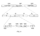
- FIG. 4 provides a schematic illustration of a DVB-T2 frame structure.
- the frame structure consists of a sequence of super frames 1001, each super frame 1001 in turn consisting of a number of T2 frames 91.
- the T2 frames each comprise a number of OFDM symbols.
- Each T2 frame begins with a P1 signalling symbol 1002, which is followed by at least one P2 signalling symbol 1003 and then a sequence of data symbols 1004 which terminates in a frame closing symbol 1005.
- frames are independent of each other and may be of variable length.
- the ETSI DVB-T2 standard introduces the concept of physical layer pipes (PLPs).
- a signal conforming to the DVB-T2 standard comprises one or more physical layer pipes for carrying data streams in a time-interleaved manner. If more than one data stream is to be transmitted on the broadcast signal, it is likely that some data will be common to multiple data streams. Accordingly, if each of those data streams were to be transported on a respective physical layer pipe, the data will be repeated in more than one physical layer pipe. This is a waste of capacity, and thus the DVB-T2 standard provides a mechanism to alleviate this problem. Specifically, data that is common to more than one data stream can be conveyed by a separate common physical layer pipe.
- the common data can be extracted from the original data streams prior to transmission and conveyed by a common physical layer pipe and a set of data physical layer pipes (which carry the non-common data).
- the data conveyed by a common physical layer pipe can be multiplexed with the data conveyed by one of the data physical layer pipes to reconstruct one of the original data streams.
- the DVB-T2 standard allows a DVB-T2 signal to consist of any integer number of physical layer pipes between 1 and 255.
- Any physical layer pipe can be a common physical layer pipe or a data physical layer pipe.
- a common physical layer pipe carries data from one or more original data streams, there will be fewer common physical layer pipes than data physical layer pipes in a DVB-T2 signal.
- each data physical layer pipe in the signal may be associated with a common physical layer pipe; there may be zero or more common physical layer pipes; some data physical layer pipes may have no common physical layer pipe.
- a receiver is able to select one of the data physical layer pipes and then determine the associated common physical layer pipe (if one exists) in order to reconstruct the original data stream.
- Each physical layer pipe can convey one of 32 payload types, one of which is an MPEG transport stream.
- the DVB-T2 signal also conveys some signalling to enable the receiver to handle the physical layer pipes.
- each physical layer pipe has an identifier specified within the signal (in a PLP_ID field) which is unique within the DVB-T2 signal.
- the signalling also conveys the total number of common and data physical layer pipes in the signal (in a NUM_PLP field); whether each physical layer pipe is a common physical layer pipe or a data physical layer pipe (in PLP_TYPE fields); the payload type (in PAYLOAD_TYPE fields) and the group ID (in GROUP_ID fields).
- Associated common and data physical layer pipes will have the same group ID. Therefore, in the set of signalled data, there will be one NUM_PLP field, and one PLP_ID, PLP_TYPE, PAYLOAD_TYPE and GROUP_ID field for each PLP.
- DVB-T2 digital terrestrial television broadcasting system
- FIG 5 schematically illustrates a transmitting arrangement 300 in which a plurality of channels Ch1, Ch2, Ch3, Ch 4 and Ch5 are formed into DVB-T2 payloads for insertion into T2 frames.
- the transmitting arrangement 300 of Figure 5 may approximately correspond to the frame builder 32 illustrated in Figure 1 .
- the arrangement comprises a physical layer pipe forming circuit 320 for generating a plurality of physical layer pipes for carrying the inputted channels Ch1, Ch2, Ch3, Ch 4 and Ch5.
- the physical layer pipes generated in this case include data physical layer pipes D1, D2, D3, D4 and D5, which carry at least portions of the inputted channels Ch1, Ch2, Ch3, Ch 4 and Ch5 respectively, and common physical layer pipes C1 and C2 which each carry a portion of two or more of the inputted channels Ch1, Ch2, Ch3, Ch 4 and Ch5. More particularly, the physical layer pipe forming circuit 320 analyses the content of each of the channels Ch1, Ch2, Ch3, Ch 4 and Ch5 to determine if two or more of the channels share common data. If so, the physical layer pipe forming circuit generates a common physical layer pipe to carry the common data, and generates respective data physical layer pipes corresponding to each of the channels sharing the common data, the data physical layer pipes carrying the data of those channels which is not common. In this way, the data physical layer pipes carry less data. As a result, duplication of data on the broadcast signal is reduced, resulting in lower bandwidth requirements.
- the first common physical layer pipe C1 may for example carry data common to each of channels Ch1 and Ch2.
- the second common physical layer pipe C2 may for example carry data common to each of channels Ch4 and Ch5.
- the channel Ch3 might not include data common to another channel and might therefore be carried wholly within the data physical layer pipe D3.
- each of data physical layer pipes D 1 and D2 will be associated with the common channel C1
- each of data physical layer pipes D4 and D5 will be associated with the common channel C2.
- Data physical layer pipe D3 will not be associated with a common physical layer pipe.
- the transmitting arrangement 300 further comprises a physical layer pipe interleaver 340 which time interleaves the physical layer pipes D1 to D5, C1 and C2 to form DVB-T2 frame payloads. These payloads will be represented for example by the data symbols 1004 of Figure 4 .
- An example interleaved structure generated by the physical layer pipe interleaver is illustrated at the bottom portion of Figure 5 .
- common physical layer pipes are provided before the data physical layer pipes, and are in the present case provided in interleaved form in the payload portion 352 of a first DVB-T2 frame payload 350 and in the payload portion 362 of a second DVB-T2 frame payload 360.
- a Type 1 payload portion 354 is provided in the frame payload 350 in which a set of data physical layer pipes D1, D2 and D3 are interleaved once within the frame payload 350. Similarly the data physical layer pipes D1, D2 and D3 are interleaved once within the Type 1 payload portion 364 of the frame payload 360.
- a Type 2 payload portion 356 is provided in the frame payload 350 in which a set of data physical layer pipes D4 and D5 are interleaved multiple times within the frame payload 350.
- each of the data physical layer pipes D4 and D5 are interleaved (repeated) twice within the Type 2 payload portion 356 of the frame payload 350.
- the data physical layer pipes D4 and D5 are interleaved twice within the Type 2 payload portions 366 of the frame payload 360.
- different channels can be carried on physical layer pipes specifically configured to handle the services provided by those channels.
- an example television receiver is schematically illustrated which comprises a tuner 400, a demodulator 500 and host circuitry 600.
- the tuner 400 of Figure 6 may be considered to correspond to the tuner 102 of Figure 3
- the demodulator 500 of Figure 6 may be considered to correspond approximately to the demodulator 103 of Figure 3 .
- the television receiver is shown to be connected to a display device 700 and an input device 800, in this case a television remote control.
- the tuner 400 serves to tune an antenna 402 to a particular frequency band of the radio-frequency spectrum upon which a desired television signal is broadcast, and to output the received broadcast signal to the demodulator 500.
- the demodulator 500 comprises demodulation circuitry 510 which carries out the functions specified in the demodulator 103 shown in Figure 3 , and also comprises control circuitry 520 for controlling the operation of the demodulation circuitry 510 in response to control signals received from the host circuitry via a physical interface line 525 and an address map 540 which together implement an application programming interface for providing a control path between the host circuitry 600 and the demodulator 500.
- the demodulator 500 also comprises a PLP association storage area 530 storing a first table 532, a second table 534 and a third table 536.
- the host circuitry 600 provides controlling, decoding and outputting functions in respect of the broadcast signal.
- the host circuitry 600 comprises a decompressor/decoder 610 for decompressing and/or decoding the demodulated signal output from the demodulator 500.
- the decompressor/decoder 610 is controlled by a central processing unit 620 upon which host software 625 is executing.
- the output of the decompressor/decoder 610 is provided via a display controller 602 to the display device 700.
- the host circuitry 600 can be controlled by a user via the input device 800 which is wirelessly connected to the host circuitry via wireless receiver 660.
- the host circuitry 600 also comprises a service store 630 for storing a list of services available on the broadcast signal in association with the physical layer pipes (channels) carrying those services.
- the host software 625 running on the central processing unit 620 of the host circuitry 600 controls the operation of the demodulator 500 via an application programming interface between the host software 625 and the control circuitry 520 of the demodulator 500.
- the application programming interface is provided using the physical interface line 525 between the central processing unit 620 of the host circuitry 600 and the address map 540 of the demodulator 500, and the address map 540 itself.
- the application programming interface between the demodulator 500 and the host software 625 is defined to satisfy the control requirements.
- the application programming interface is implemented using an address map 540, which is a set of memory locations (in the present example provided in the demodulator 500) each having a unique address. Each of the memory locations can be read from by the host software, and some of the memory locations can be written to by the host software.
- Information can be transferred from the demodulator 500 to the host software 625 running on the host circuitry 600 by reading from a memory location in the address map 540, whereas information can be transferred from the host software 625 to the demodulator 500 by writing to a memory location in the address map 540.
- the application programming interface between the host software 625 and the demodulator 500 is implemented in part by the physical interface 525 between the host circuitry 600 and the demodulator 500.
- This interface has a limited bandwidth and the more data which is passed across it, the more electrical noise is likely to be generated. This electrical noise may interfere with the sensitive electronic circuitry in the tuner circuitry and demodulator 500, in turn degrading the performance of the television receiver.
- the receiver, and in particular the host circuitry 600 will build up a database of available services in the service store 630.
- This database associates data physical layer pipe identifiers with services.
- Each data physical layer pipe identifier may be associated with one or more services.
- Embodiments of the present invention avoid the requirement for the database in the service store to store the common physical layer pipe identifiers associated with each data physical layer pipe identifiers in the case that there are common physical layer pipes present in the DVB-T2 signal.
- the process of building up this service list is sometimes referred to as channel scanning.
- the list of services is output to the display device 700 via the display controller 602.
- the receiver will then determine the associated data physical layer pipe identifier from the database in the service store 630 and also, in a manner described below, whether there is an associated common physical layer pipe and if so, the common physical layer pipe identifier. Once the physical layer pipe identifiers have been determined, the receiver can multiplex the data conveyed by the selected data physical layer pipe with the data conveyed by the associated common physical layer pipe in order to reconstruct one of the original data streams and, thus, give the TV user access to the desired service. This process is sometimes called channel zapping.
- the channel scanning and channel zapping functionality may be implemented partly by the host software and partly by the demodulator circuitry.
- One way of partitioning this functionality would be for the demodulator circuitry to make all of the signalling transmitted within the DVB-T2 signal available to the host software via the application programming interface and, during the channel scan process, for the host software to build up a database of available services which associates services with data physical layer pipe identifiers, with whether there is an associated common physical layer pipe and, if so, with the common physical layer pipe identifier. Then, when the TV user wishes to select a service, the host software will then determine the associated data physical layer pipe identifier from the database in the service store and also whether there is an associated common physical layer pipe and, if so, its identifier.
- the host software could write the physical layer pipe identifiers across the application programming interface to the demodulator 500 to enable it to multiplex the data conveyed by the selected data physical layer pipe with the data conveyed by the associated common physical layer pipe in order to reconstruct the original data stream and, thus, give the TV user access to the desired service.
- a disadvantage of this mode of operation is that the amount of data communicated between the demodulator 500 and the host circuitry 600 would be relatively large, thus wasting bandwidth and generating undesirable amounts of electrical noise in the physical interface.
- An improved way of partitioning the functionality between the demodulator 500 and the host circuitry 600 is for the demodulator 500 to make the number of data physical layer pipes transmitted within the DVB-T2 signal - N dataPLPs - and a list of the data physical layer pipes available to the host software via the application programming interface and, during the channel scan process, for the host software to build up a database of available services which associates services with the data physical layer pipe identifiers. Then, during both the channel scan and channel zap processes, the demodulator would build up a database which associates each data physical layer pipe identifier with whether there is an associated common physical layer pipe and, if so, with the respective common physical layer pipe identifier.
- the host software will determine the associated data physical layer pipe identifier from its database and will then write this across the application programming interface to the demodulator.
- the demodulator will then multiplex the data conveyed by the selected data physical layer pipe with the data conveyed by the associated common physical layer pipe in order to reconstruct the original data stream and, thus, give the TV user access to the desired service.
- a DVB-T2 demodulator circuit may only be capable of processing physical layer pipes which convey a subset of payload types.
- a DVB-T2 demodulator that is only capable of processing physical layer pipes which convey MPEG transport streams.
- the demodulator would ignore data physical layer pipes which do not convey unsupported payload types and so the number of data physical layer pipes to be transferred across the application programming interface to the host software would in fact be the number of data physical layer pipes which convey supported payload types. This would advantageously reduce the bandwidth requirements of the physical interface and reduce the time taken to conduct channel scanning.
- the demodulator circuitry selects one by default. For example, the demodulator circuitry could select the first data physical layer pipe it discovers and the corresponding common physical layer pipe if a common physical layer pipe is associated with the default data physical layer pipe.
- a section of an example address map which could implement the application programming interface is: R NUM_DATA_PLPS RW DATA_PLP_INDEX R READ_PLP_ID RW PLP_SELECT
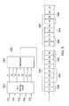
- FIG. 7 This address map is schematically illustrated in Figure 7 .
- the address map 540 shown in Figure 6 is illustrated in more detail.
- the address map 540 is provided within the demodulator 500 and serves as part of the interface between the control circuitry 520 of the demodulator 500 and the host software 625 running on the host circuitry 600.
- a first memory location 542 stores a value NUM_DATA_PLPS which indicates the number of data physical layer pipes present in a currently received broadcast signal.
- the value NUM_DATA_PLPS is obtained by the demodulator from the signalling portion of the broadcast signal and is then written into the first memory location.
- the symbol "R" above indicates that the first memory location is readable by the host circuitry 600.
- Figure 7 which includes directional arrows 541 a and 54 1 b indicating that data is written to the first memory location 542 by the control circuitry 520 and read from the first memory location by the host circuitry 600.
- the address map also comprises a second memory location 544 which stores a value DATA_PLP_INDEX which can be specified by the host circuitry 600 in a process of acquiring data physical layer pipe identifiers, as will be described below.
- the symbol "RW" indicates that the first memory location can be written to by the host circuitry 600. This is also apparent from Figure 7 , which includes directional arrows 543a and 543b indicating that data is written to the second memory location 544 by the host circuitry 600 and read from the second memory location by the control circuitry 520.
- the address map also comprises a third memory location 546 which stores a value READ_PLP_ID which is populated by the demodulator 500 with a data PLP identifier read from a table using the DATA_PLP_INDEX specified in the second memory location by the host circuitry 600.
- the third memory location 546 is readable by the host circuitry 600 to acquire the data physical layer pipe identifiers extracted from the broadcast signal.
- the symbol "R” indicates that the third memory location 546 is readable by the host circuitry 600, but cannot be written to by the host circuitry 600.
- Figure 7 which includes directional arrows 545a and 545b indicating that data is written to the third memory location 546 by the control circuitry 520 and read from the third memory location 546 the host circuitry 600.
- the address map comprises a fourth memory location 548 which stores a value PLP_SELECT which is populated by the host circuitry 600 with a data PLP identifier selected by the host circuitry 600 for demodulation.
- the fourth memory location can be written to by the host circuitry 600, as is apparent from Figure 7 , which includes directional arrows 547a and 547b indicating that data is written to the fourth memory location 548 by the host circuitry 600 and read from the fourth memory location 548 by the control circuitry 520.
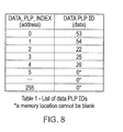
- the host software reads the number of data physical layer pipes from NUM_DATA_PLPS via the first memory location in the address map. Then, the host circuitry writes an index value between 0 and NUM_DATA_PLPS - 1 to DATA_PLP_INDEX via the second memory location in the address map. Then, the host circuitry reads the corresponding data physical layer pipe identifier from READ_PLP_ID via the third memory location in the address map. In this way, by holding at the demodulator a list of available data physical layer pipe identifiers indexed by sequential values from 0 to NUM_DATA_PLPS - 1, the list can be efficiently transferred by the present technique. In the C programming language, the relevant portion of the host software might resemble:
- Line 1 of the above program code declares a 256 cell integer array to store received data physical layer pipes received from the demodulator via the application programming interface.
- Lines 2 and 3 declare the variables PLPindex and numPLP_IDs.
- Line 4 obtains the number of data physical layer pipes from the first memory location of the address map using the APIread command.
- Lines 5 to 7 set up a loop to sequentially apply an index value of between 0 and numPLP_IDs - 1 to the second memory location of the memory map in the demodulator 500 using an APlwrite command and read the corresponding data physical layer pipe identifier from the third memory location using the APIread command.
- the host software is able to build up a list of data physical layer pipes from the indexed list stored at the demodulator 500. This list is then associated with services at the host circuitry 600 to form the service database stored in the service store 630.
- the host software writes one the data physical layer pipe identifier corresponding to a selected one of the data physical layer pipes from its service database to the fourth memory location location 548 to specify the PLP_SELECT value, which is then referred to by the control circuitry 520 of the demodulator 500 to select the physical layer pipes which are to be demodulated.
- the broadcast signalling described above will be received sequentially.
- the first field received in the control signalling is the number of PLPs - NUM_PLP.
- the PLP_ID, PLP_TYPE and GROUP_ID fields are received in turn for each PLP.
- the hardware builds up three tables:
- the value of the fourth (SELECT_PLP) API memory location and the output of the third table give a data physical layer pipe identifier and a flag to signal whether a common physical layer pipe exists for that data physical layer pipe, and if so, the corresponding common physical layer pipe identifier.
- the data physical layer pipe identifier and (if present) the common physical layer pipe identifier are then used by the demodulation circuitry 510 of the demodulator 500 to demodulate the service selected by the user.
- the hardware would parse the DVB-T2 signalling PAYLOAD_TYPE fields and would ignore any physical layer pipe that conveys an unsupported payload type.
- the demodulator 500 is set to select a default physical layer pipe in the absence of a selection by the user, then by convention, the data physical layer pipe identifier specified in the first row of the first table could be designated as being the default location, which would output a default physical layer pipe identifier.
- the mechanism of the second and third tables would then generate a flag to signal whether a common physical layer pipe exists for that data physical layer pipe, and if so, the corresponding physical layer pipe identifier.
- other default physical layer pipe selection schemes could be used, such as selecting a most recently watched channel, or selecting from a default channel list specified by the user.
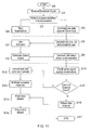
- the process starts at a step S1, which may be initiated for example when the television receiver is first switched on.
- the broadcast signal is received via an aerial and tuner unit and provided to a demodulator.
- the broadcast signal is parsed, and control signalling provided within the broadcast signal is processed to extract PLP identifiers and associations between the physical layer pipes at a step S3.
- the identifiers may be those provided within the PLP_ID fields of a DVB-T2 signal, and the associations may be provided by the GROUP_ID fields of a DVB-T2 signal.
- the associations are stored within the demodulator, and a list of the data PLP identifiers extracted from the broadcast signal by the demodulator are communicated to host circuitry at a step S5.
- the host circuitry is able to build up a list of available services for presentation to a user at a step S6, and the user is able to make a selection from amongst these services at a step S7.
- the host circuitry then generates a selection signal at a step S8 in dependence on the data PLP identifier which corresponds to the selected service, and then communicates the selection signal to the demodulator at a step S9.
- the demodulator checks the selection signal against the association between data physical layer pipes and common physical layer pipes stored at the step S4.
- a step S 11 it is determined, based on the stored association, whether a common physical layer pipe exists which corresponds to the selected data physical layer pipe. If a common physical layer pipe is determined to exist, then at a step S 12 the demodulator extracts from the broadcast signal both the data physical layer pipe and the associated common physical layer pipe. Then, at a step S 13, the extracted data and common physical layer pipes are multiplexed together. The multiplexed physical layer pipes are then formed into a data stream at the step S14 and output (either for direct output or decompression/decoding) at a step S15.
- step S11 If at the step S11 it is determined that no common physical layer pipe exists which corresponds to the selected data physical layer pipe, then at a step S16 the selected data physical layer pipe is extracted from the broadcast signal by the demodulator, and is then formed into a data stream and output at the steps S 14 and S 15 respectively. The process terminates at a step S17.
- aspects of the invention may be implemented in the form of a computer program product comprising processor executable instructions stored on a data carrier such as a floppy disk, optical disk, hard disk, PROM, RAM, flash memory or any combination of these or other storage media, or transmitted via data signals on a network such as an Ethernet, a wireless network, the Internet, or any combination of these of other networks, or realised in hardware as an ASIC (application specific integrated circuit) or an FPGA (field programmable gate array) or other configurable or bespoke circuit suitable to use in adapting the conventional equivalent device.
- a data carrier such as a floppy disk, optical disk, hard disk, PROM, RAM, flash memory or any combination of these or other storage media, or transmitted via data signals on a network such as an Ethernet, a wireless network, the Internet, or any combination of these of other networks, or realised in hardware as an ASIC (application specific integrated circuit) or an FPGA (field programmable gate array) or other configurable or bespoke circuit suitable to use in adapting the conventional equivalent device.
- Embodiments of the present invention may also find application with other appropriate transmission standards such as the cable transmission standard known as DVB-C2.
- DVB-C2 the cable transmission standard
- the OFDM symbols are not transmitted and received via a radio frequency carrier, but via cable and so an appropriate adaptation of the transmitter and receiver architecture can be made.
- the present invention is not limited to application with DVB and may be extended to other standards for transmission or reception, both fixed and mobile.
Landscapes
- Engineering & Computer Science (AREA)
- Signal Processing (AREA)
- Multimedia (AREA)
- Computer Networks & Wireless Communication (AREA)
- Two-Way Televisions, Distribution Of Moving Picture Or The Like (AREA)
- Circuits Of Receivers In General (AREA)
Applications Claiming Priority (1)
| Application Number | Priority Date | Filing Date | Title |
|---|---|---|---|
| GB0909586A GB2470756B (en) | 2009-06-03 | 2009-06-03 | Broadcast receiver and method |
Publications (3)
| Publication Number | Publication Date |
|---|---|
| EP2268004A2 true EP2268004A2 (de) | 2010-12-29 |
| EP2268004A3 EP2268004A3 (de) | 2012-10-31 |
| EP2268004B1 EP2268004B1 (de) | 2018-11-28 |
Family
ID=40902555
Family Applications (1)
| Application Number | Title | Priority Date | Filing Date |
|---|---|---|---|
| EP10275050.2A Active EP2268004B1 (de) | 2009-06-03 | 2010-05-04 | Rundfunkempfänger und Verfahren |
Country Status (5)
| Country | Link |
|---|---|
| EP (1) | EP2268004B1 (de) |
| KR (1) | KR20100130560A (de) |
| CN (1) | CN101909176B (de) |
| GB (1) | GB2470756B (de) |
| TW (1) | TWI532380B (de) |
Cited By (8)
| Publication number | Priority date | Publication date | Assignee | Title |
|---|---|---|---|---|
| WO2012175787A1 (en) * | 2011-06-24 | 2012-12-27 | Nokia Corporation | Accessing service guide information in a digital video broadcast system |
| US8498272B2 (en) | 2010-08-26 | 2013-07-30 | Nokia Corporation | Providing signaling information and performing a handover using the signaling information |
| US8744010B2 (en) | 2011-05-12 | 2014-06-03 | Nokia Corporation | Providing signaling information in an electronic service guide |
| US8787237B2 (en) | 2011-11-16 | 2014-07-22 | Nokia Corporation | Method and system to enable handover in a hybrid terrestrial satellite network |
| WO2017150937A1 (ko) * | 2016-03-04 | 2017-09-08 | 삼성전자 주식회사 | 수신기 및 그의 plp 처리 방법 |
| US9838748B2 (en) | 2013-07-05 | 2017-12-05 | Samsung Electronics Co., Ltd. | Transmitting apparatus and receiving apparatus, and signal processing method thereof |
| US9942000B2 (en) | 2015-08-05 | 2018-04-10 | Samsung Electronics Co., Ltd. | Broadcast receiving apparatus and signal processing method thereof |
| WO2018117282A1 (ko) * | 2016-12-19 | 2018-06-28 | 엘지전자 주식회사 | 방송 신호 송신 장치, 방송 신호 수신 장치, 방송 신호 송신 방법, 및 방송 신호 수신 방법 |
Families Citing this family (4)
| Publication number | Priority date | Publication date | Assignee | Title |
|---|---|---|---|---|
| GB2489750A (en) * | 2011-04-08 | 2012-10-10 | Samsung Electronics Co Ltd | Frame structure and signalling for wireless broadcast system |
| CN104113716A (zh) * | 2013-04-16 | 2014-10-22 | 扬智科技股份有限公司 | 数码视频广播接收模块及其运作方法 |
| CN106658547A (zh) * | 2015-10-30 | 2017-05-10 | 北京信威通信技术股份有限公司 | 基于McWiLL协议的数据包检测方法及物理层设备 |
| JP2019216325A (ja) * | 2018-06-12 | 2019-12-19 | ソニーセミコンダクタソリューションズ株式会社 | 受信装置、および、受信装置の制御方法 |
Family Cites Families (3)
| Publication number | Priority date | Publication date | Assignee | Title |
|---|---|---|---|---|
| US7334132B1 (en) * | 2003-06-27 | 2008-02-19 | Zoran Corporation | Flexible and scalable architecture for transport processing |
| KR101490262B1 (ko) * | 2008-01-02 | 2015-02-05 | 엘지전자 주식회사 | 신호 송수신 방법 및 신호 송수신 장치 |
| KR100937429B1 (ko) * | 2008-02-04 | 2010-01-18 | 엘지전자 주식회사 | 신호 송수신 방법 및 신호 송수신 장치 |
-
2009
- 2009-06-03 GB GB0909586A patent/GB2470756B/en not_active Expired - Fee Related
-
2010
- 2010-05-04 EP EP10275050.2A patent/EP2268004B1/de active Active
- 2010-05-11 TW TW099114945A patent/TWI532380B/zh active
- 2010-06-01 KR KR1020100051912A patent/KR20100130560A/ko not_active Withdrawn
- 2010-06-03 CN CN201010196350.1A patent/CN101909176B/zh active Active
Non-Patent Citations (1)
| Title |
|---|
| None |
Cited By (12)
| Publication number | Priority date | Publication date | Assignee | Title |
|---|---|---|---|---|
| US8498272B2 (en) | 2010-08-26 | 2013-07-30 | Nokia Corporation | Providing signaling information and performing a handover using the signaling information |
| US8744010B2 (en) | 2011-05-12 | 2014-06-03 | Nokia Corporation | Providing signaling information in an electronic service guide |
| WO2012175787A1 (en) * | 2011-06-24 | 2012-12-27 | Nokia Corporation | Accessing service guide information in a digital video broadcast system |
| US9584238B2 (en) | 2011-06-24 | 2017-02-28 | Nokia Corporation | Accessing service guide information in a digital video broadcast system |
| US8787237B2 (en) | 2011-11-16 | 2014-07-22 | Nokia Corporation | Method and system to enable handover in a hybrid terrestrial satellite network |
| US9838748B2 (en) | 2013-07-05 | 2017-12-05 | Samsung Electronics Co., Ltd. | Transmitting apparatus and receiving apparatus, and signal processing method thereof |
| US9942000B2 (en) | 2015-08-05 | 2018-04-10 | Samsung Electronics Co., Ltd. | Broadcast receiving apparatus and signal processing method thereof |
| US10484128B2 (en) | 2015-08-05 | 2019-11-19 | Samsung Electronics Co., Ltd. | Broadcast receiving apparatus and signal processing method thereof |
| WO2017150937A1 (ko) * | 2016-03-04 | 2017-09-08 | 삼성전자 주식회사 | 수신기 및 그의 plp 처리 방법 |
| CN108781306A (zh) * | 2016-03-04 | 2018-11-09 | 三星电子株式会社 | 接收装置及其plp处理方法 |
| US11202112B2 (en) | 2016-03-04 | 2021-12-14 | Samsung Electronics Co., Ltd. | Receiver and PLP processing method therefor |
| WO2018117282A1 (ko) * | 2016-12-19 | 2018-06-28 | 엘지전자 주식회사 | 방송 신호 송신 장치, 방송 신호 수신 장치, 방송 신호 송신 방법, 및 방송 신호 수신 방법 |
Also Published As
| Publication number | Publication date |
|---|---|
| GB2470756A (en) | 2010-12-08 |
| KR20100130560A (ko) | 2010-12-13 |
| EP2268004A3 (de) | 2012-10-31 |
| GB0909586D0 (en) | 2009-07-15 |
| TW201110695A (en) | 2011-03-16 |
| CN101909176A (zh) | 2010-12-08 |
| GB2470756B (en) | 2014-08-06 |
| EP2268004B1 (de) | 2018-11-28 |
| CN101909176B (zh) | 2014-10-08 |
| TWI532380B (zh) | 2016-05-01 |
Similar Documents
| Publication | Publication Date | Title |
|---|---|---|
| EP2268004B1 (de) | Rundfunkempfänger und Verfahren | |
| US20220174374A1 (en) | Method for transmitting broadcast signals and method for receiving broadcast signals | |
| US20190253212A1 (en) | Demapping apparatus and method for reception of data in a multi-carrier broadcast system | |
| US8498312B2 (en) | Transmission of physical layer signaling in a broadcast system | |
| CN102833587B (zh) | 多载波传输系统中的发送和接收装置及方法 | |
| CN102246457B (zh) | 用于发送和接收信号的方法及用于发送和接收信号的装置 | |
| US10313718B2 (en) | System physical layer pipe for a digital television system | |
| WO2010142853A1 (en) | Baseband frame header modifications for digital video broadcasting | |
| KR102414006B1 (ko) | 브로드캐스트 시스템에서의 제어 시그널링 | |
| CN101361302A (zh) | 在tps比特中以信号通知相邻信号的方法和系统 | |
| WO2011068505A1 (en) | Multiple levels of robustness within a single physical layer pipe | |
| KR20160106099A (ko) | 디지털 방송 시스템에서 시그널링 정보를 송수신하는 장치 및 방법 | |
| EP3244585A1 (de) | Vorrichtung und verfahren zur kombination verschiedener signalschichten von ldm-signalen |
Legal Events
| Date | Code | Title | Description |
|---|---|---|---|
| PUAI | Public reference made under article 153(3) epc to a published international application that has entered the european phase |
Free format text: ORIGINAL CODE: 0009012 |
|
| AK | Designated contracting states |
Kind code of ref document: A2 Designated state(s): AL AT BE BG CH CY CZ DE DK EE ES FI FR GB GR HR HU IE IS IT LI LT LU LV MC MK MT NL NO PL PT RO SE SI SK SM TR |
|
| AX | Request for extension of the european patent |
Extension state: BA ME RS |
|
| PUAL | Search report despatched |
Free format text: ORIGINAL CODE: 0009013 |
|
| AK | Designated contracting states |
Kind code of ref document: A3 Designated state(s): AL AT BE BG CH CY CZ DE DK EE ES FI FR GB GR HR HU IE IS IT LI LT LU LV MC MK MT NL NO PL PT RO SE SI SK SM TR |
|
| AX | Request for extension of the european patent |
Extension state: BA ME RS |
|
| RIC1 | Information provided on ipc code assigned before grant |
Ipc: H04N 21/426 20110101ALI20120921BHEP Ipc: H04N 21/4385 20110101ALI20120921BHEP Ipc: H04N 5/44 20110101AFI20120921BHEP |
|
| 17P | Request for examination filed |
Effective date: 20130430 |
|
| RAP1 | Party data changed (applicant data changed or rights of an application transferred) |
Owner name: SONY UNITED KINGDOM LIMITED Owner name: SONY CORPORATION |
|
| RAP1 | Party data changed (applicant data changed or rights of an application transferred) |
Owner name: SONY EUROPE LIMITED Owner name: SONY CORPORATION |
|
| 17Q | First examination report despatched |
Effective date: 20140828 |
|
| RAP1 | Party data changed (applicant data changed or rights of an application transferred) |
Owner name: SONY EUROPE LIMITED Owner name: SATURN LICENSING LLC |
|
| RAP1 | Party data changed (applicant data changed or rights of an application transferred) |
Owner name: SATURN LICENSING LLC |
|
| GRAP | Despatch of communication of intention to grant a patent |
Free format text: ORIGINAL CODE: EPIDOSNIGR1 |
|
| STAA | Information on the status of an ep patent application or granted ep patent |
Free format text: STATUS: GRANT OF PATENT IS INTENDED |
|
| INTG | Intention to grant announced |
Effective date: 20180613 |
|
| GRAS | Grant fee paid |
Free format text: ORIGINAL CODE: EPIDOSNIGR3 |
|
| GRAA | (expected) grant |
Free format text: ORIGINAL CODE: 0009210 |
|
| STAA | Information on the status of an ep patent application or granted ep patent |
Free format text: STATUS: THE PATENT HAS BEEN GRANTED |
|
| AK | Designated contracting states |
Kind code of ref document: B1 Designated state(s): AL AT BE BG CH CY CZ DE DK EE ES FI FR GB GR HR HU IE IS IT LI LT LU LV MC MK MT NL NO PL PT RO SE SI SK SM TR |
|
| REG | Reference to a national code |
Ref country code: GB Ref legal event code: FG4D |
|
| REG | Reference to a national code |
Ref country code: CH Ref legal event code: EP |
|
| REG | Reference to a national code |
Ref country code: DE Ref legal event code: R096 Ref document number: 602010055411 Country of ref document: DE |
|
| REG | Reference to a national code |
Ref country code: CH Ref legal event code: PK Free format text: BERICHTIGUNGEN |
|
| REG | Reference to a national code |
Ref country code: AT Ref legal event code: REF Ref document number: 1071653 Country of ref document: AT Kind code of ref document: T Effective date: 20181215 |
|
| REG | Reference to a national code |
Ref country code: IE Ref legal event code: FG4D |
|
| RIC2 | Information provided on ipc code assigned after grant |
Ipc: H04N 5/44 20110101AFI20120921BHEP Ipc: H04N 21/426 20110101ALI20120921BHEP Ipc: H04N 21/4385 20110101ALI20120921BHEP |
|
| REG | Reference to a national code |
Ref country code: CH Ref legal event code: PK Free format text: BERICHTIGUNGEN |
|
| RIC2 | Information provided on ipc code assigned after grant |
Ipc: H04N 21/426 20110101ALI20120921BHEP Ipc: H04N 21/4385 20110101ALI20120921BHEP Ipc: H04N 5/44 20110101AFI20120921BHEP |
|
| REG | Reference to a national code |
Ref country code: NL Ref legal event code: FP |
|
| REG | Reference to a national code |
Ref country code: LT Ref legal event code: MG4D |
|
| REG | Reference to a national code |
Ref country code: AT Ref legal event code: MK05 Ref document number: 1071653 Country of ref document: AT Kind code of ref document: T Effective date: 20181128 |
|
| PG25 | Lapsed in a contracting state [announced via postgrant information from national office to epo] |
Ref country code: IS Free format text: LAPSE BECAUSE OF FAILURE TO SUBMIT A TRANSLATION OF THE DESCRIPTION OR TO PAY THE FEE WITHIN THE PRESCRIBED TIME-LIMIT Effective date: 20190328 Ref country code: FI Free format text: LAPSE BECAUSE OF FAILURE TO SUBMIT A TRANSLATION OF THE DESCRIPTION OR TO PAY THE FEE WITHIN THE PRESCRIBED TIME-LIMIT Effective date: 20181128 Ref country code: NO Free format text: LAPSE BECAUSE OF FAILURE TO SUBMIT A TRANSLATION OF THE DESCRIPTION OR TO PAY THE FEE WITHIN THE PRESCRIBED TIME-LIMIT Effective date: 20190228 Ref country code: AT Free format text: LAPSE BECAUSE OF FAILURE TO SUBMIT A TRANSLATION OF THE DESCRIPTION OR TO PAY THE FEE WITHIN THE PRESCRIBED TIME-LIMIT Effective date: 20181128 Ref country code: ES Free format text: LAPSE BECAUSE OF FAILURE TO SUBMIT A TRANSLATION OF THE DESCRIPTION OR TO PAY THE FEE WITHIN THE PRESCRIBED TIME-LIMIT Effective date: 20181128 Ref country code: LV Free format text: LAPSE BECAUSE OF FAILURE TO SUBMIT A TRANSLATION OF THE DESCRIPTION OR TO PAY THE FEE WITHIN THE PRESCRIBED TIME-LIMIT Effective date: 20181128 Ref country code: HR Free format text: LAPSE BECAUSE OF FAILURE TO SUBMIT A TRANSLATION OF THE DESCRIPTION OR TO PAY THE FEE WITHIN THE PRESCRIBED TIME-LIMIT Effective date: 20181128 Ref country code: LT Free format text: LAPSE BECAUSE OF FAILURE TO SUBMIT A TRANSLATION OF THE DESCRIPTION OR TO PAY THE FEE WITHIN THE PRESCRIBED TIME-LIMIT Effective date: 20181128 Ref country code: BG Free format text: LAPSE BECAUSE OF FAILURE TO SUBMIT A TRANSLATION OF THE DESCRIPTION OR TO PAY THE FEE WITHIN THE PRESCRIBED TIME-LIMIT Effective date: 20190228 |
|
| PG25 | Lapsed in a contracting state [announced via postgrant information from national office to epo] |
Ref country code: PT Free format text: LAPSE BECAUSE OF FAILURE TO SUBMIT A TRANSLATION OF THE DESCRIPTION OR TO PAY THE FEE WITHIN THE PRESCRIBED TIME-LIMIT Effective date: 20190328 Ref country code: AL Free format text: LAPSE BECAUSE OF FAILURE TO SUBMIT A TRANSLATION OF THE DESCRIPTION OR TO PAY THE FEE WITHIN THE PRESCRIBED TIME-LIMIT Effective date: 20181128 Ref country code: SE Free format text: LAPSE BECAUSE OF FAILURE TO SUBMIT A TRANSLATION OF THE DESCRIPTION OR TO PAY THE FEE WITHIN THE PRESCRIBED TIME-LIMIT Effective date: 20181128 Ref country code: GR Free format text: LAPSE BECAUSE OF FAILURE TO SUBMIT A TRANSLATION OF THE DESCRIPTION OR TO PAY THE FEE WITHIN THE PRESCRIBED TIME-LIMIT Effective date: 20190301 |
|
| PG25 | Lapsed in a contracting state [announced via postgrant information from national office to epo] |
Ref country code: CZ Free format text: LAPSE BECAUSE OF FAILURE TO SUBMIT A TRANSLATION OF THE DESCRIPTION OR TO PAY THE FEE WITHIN THE PRESCRIBED TIME-LIMIT Effective date: 20181128 Ref country code: PL Free format text: LAPSE BECAUSE OF FAILURE TO SUBMIT A TRANSLATION OF THE DESCRIPTION OR TO PAY THE FEE WITHIN THE PRESCRIBED TIME-LIMIT Effective date: 20181128 Ref country code: DK Free format text: LAPSE BECAUSE OF FAILURE TO SUBMIT A TRANSLATION OF THE DESCRIPTION OR TO PAY THE FEE WITHIN THE PRESCRIBED TIME-LIMIT Effective date: 20181128 Ref country code: IT Free format text: LAPSE BECAUSE OF FAILURE TO SUBMIT A TRANSLATION OF THE DESCRIPTION OR TO PAY THE FEE WITHIN THE PRESCRIBED TIME-LIMIT Effective date: 20181128 |
|
| REG | Reference to a national code |
Ref country code: DE Ref legal event code: R097 Ref document number: 602010055411 Country of ref document: DE |
|
| PG25 | Lapsed in a contracting state [announced via postgrant information from national office to epo] |
Ref country code: EE Free format text: LAPSE BECAUSE OF FAILURE TO SUBMIT A TRANSLATION OF THE DESCRIPTION OR TO PAY THE FEE WITHIN THE PRESCRIBED TIME-LIMIT Effective date: 20181128 Ref country code: SM Free format text: LAPSE BECAUSE OF FAILURE TO SUBMIT A TRANSLATION OF THE DESCRIPTION OR TO PAY THE FEE WITHIN THE PRESCRIBED TIME-LIMIT Effective date: 20181128 Ref country code: RO Free format text: LAPSE BECAUSE OF FAILURE TO SUBMIT A TRANSLATION OF THE DESCRIPTION OR TO PAY THE FEE WITHIN THE PRESCRIBED TIME-LIMIT Effective date: 20181128 Ref country code: SK Free format text: LAPSE BECAUSE OF FAILURE TO SUBMIT A TRANSLATION OF THE DESCRIPTION OR TO PAY THE FEE WITHIN THE PRESCRIBED TIME-LIMIT Effective date: 20181128 |
|
| PLBE | No opposition filed within time limit |
Free format text: ORIGINAL CODE: 0009261 |
|
| STAA | Information on the status of an ep patent application or granted ep patent |
Free format text: STATUS: NO OPPOSITION FILED WITHIN TIME LIMIT |
|
| PG25 | Lapsed in a contracting state [announced via postgrant information from national office to epo] |
Ref country code: SI Free format text: LAPSE BECAUSE OF FAILURE TO SUBMIT A TRANSLATION OF THE DESCRIPTION OR TO PAY THE FEE WITHIN THE PRESCRIBED TIME-LIMIT Effective date: 20181128 |
|
| 26N | No opposition filed |
Effective date: 20190829 |
|
| REG | Reference to a national code |
Ref country code: CH Ref legal event code: PL |
|
| PG25 | Lapsed in a contracting state [announced via postgrant information from national office to epo] |
Ref country code: CH Free format text: LAPSE BECAUSE OF NON-PAYMENT OF DUE FEES Effective date: 20190531 Ref country code: MC Free format text: LAPSE BECAUSE OF FAILURE TO SUBMIT A TRANSLATION OF THE DESCRIPTION OR TO PAY THE FEE WITHIN THE PRESCRIBED TIME-LIMIT Effective date: 20181128 Ref country code: LI Free format text: LAPSE BECAUSE OF NON-PAYMENT OF DUE FEES Effective date: 20190531 |
|
| REG | Reference to a national code |
Ref country code: BE Ref legal event code: MM Effective date: 20190531 |
|
| PG25 | Lapsed in a contracting state [announced via postgrant information from national office to epo] |
Ref country code: LU Free format text: LAPSE BECAUSE OF NON-PAYMENT OF DUE FEES Effective date: 20190504 |
|
| PG25 | Lapsed in a contracting state [announced via postgrant information from national office to epo] |
Ref country code: TR Free format text: LAPSE BECAUSE OF FAILURE TO SUBMIT A TRANSLATION OF THE DESCRIPTION OR TO PAY THE FEE WITHIN THE PRESCRIBED TIME-LIMIT Effective date: 20181128 |
|
| PG25 | Lapsed in a contracting state [announced via postgrant information from national office to epo] |
Ref country code: IE Free format text: LAPSE BECAUSE OF NON-PAYMENT OF DUE FEES Effective date: 20190504 |
|
| PG25 | Lapsed in a contracting state [announced via postgrant information from national office to epo] |
Ref country code: BE Free format text: LAPSE BECAUSE OF NON-PAYMENT OF DUE FEES Effective date: 20190531 |
|
| PG25 | Lapsed in a contracting state [announced via postgrant information from national office to epo] |
Ref country code: CY Free format text: LAPSE BECAUSE OF FAILURE TO SUBMIT A TRANSLATION OF THE DESCRIPTION OR TO PAY THE FEE WITHIN THE PRESCRIBED TIME-LIMIT Effective date: 20181128 |
|
| PG25 | Lapsed in a contracting state [announced via postgrant information from national office to epo] |
Ref country code: HU Free format text: LAPSE BECAUSE OF FAILURE TO SUBMIT A TRANSLATION OF THE DESCRIPTION OR TO PAY THE FEE WITHIN THE PRESCRIBED TIME-LIMIT; INVALID AB INITIO Effective date: 20100504 Ref country code: MT Free format text: LAPSE BECAUSE OF FAILURE TO SUBMIT A TRANSLATION OF THE DESCRIPTION OR TO PAY THE FEE WITHIN THE PRESCRIBED TIME-LIMIT Effective date: 20181128 |
|
| PG25 | Lapsed in a contracting state [announced via postgrant information from national office to epo] |
Ref country code: MK Free format text: LAPSE BECAUSE OF FAILURE TO SUBMIT A TRANSLATION OF THE DESCRIPTION OR TO PAY THE FEE WITHIN THE PRESCRIBED TIME-LIMIT Effective date: 20181128 |
|
| P01 | Opt-out of the competence of the unified patent court (upc) registered |
Effective date: 20230514 |
|
| PGFP | Annual fee paid to national office [announced via postgrant information from national office to epo] |
Ref country code: NL Payment date: 20250526 Year of fee payment: 16 |
|
| PGFP | Annual fee paid to national office [announced via postgrant information from national office to epo] |
Ref country code: DE Payment date: 20250528 Year of fee payment: 16 |
|
| PGFP | Annual fee paid to national office [announced via postgrant information from national office to epo] |
Ref country code: GB Payment date: 20250520 Year of fee payment: 16 |
|
| PGFP | Annual fee paid to national office [announced via postgrant information from national office to epo] |
Ref country code: FR Payment date: 20250526 Year of fee payment: 16 |