EP2267477A1 - A method for detecting a distance, a radar system and a computer program product - Google Patents
A method for detecting a distance, a radar system and a computer program product Download PDFInfo
- Publication number
- EP2267477A1 EP2267477A1 EP20090163020 EP09163020A EP2267477A1 EP 2267477 A1 EP2267477 A1 EP 2267477A1 EP 20090163020 EP20090163020 EP 20090163020 EP 09163020 A EP09163020 A EP 09163020A EP 2267477 A1 EP2267477 A1 EP 2267477A1
- Authority
- EP
- European Patent Office
- Prior art keywords
- signal
- radar system
- reflecting surface
- harmonics
- frequency
- Prior art date
- Legal status (The legal status is an assumption and is not a legal conclusion. Google has not performed a legal analysis and makes no representation as to the accuracy of the status listed.)
- Withdrawn
Links
- 238000000034 method Methods 0.000 title claims abstract description 32
- 238000004590 computer program Methods 0.000 title claims description 6
- 230000010363 phase shift Effects 0.000 claims abstract description 31
- 238000001514 detection method Methods 0.000 claims description 33
- 238000012545 processing Methods 0.000 claims description 11
- 238000001914 filtration Methods 0.000 claims description 5
- 238000001228 spectrum Methods 0.000 description 11
- 230000000694 effects Effects 0.000 description 7
- 238000004088 simulation Methods 0.000 description 5
- 230000007704 transition Effects 0.000 description 5
- 238000010200 validation analysis Methods 0.000 description 5
- 238000010586 diagram Methods 0.000 description 4
- 238000005259 measurement Methods 0.000 description 4
- NCGICGYLBXGBGN-UHFFFAOYSA-N 3-morpholin-4-yl-1-oxa-3-azonia-2-azanidacyclopent-3-en-5-imine;hydrochloride Chemical compound Cl.[N-]1OC(=N)C=[N+]1N1CCOCC1 NCGICGYLBXGBGN-UHFFFAOYSA-N 0.000 description 3
- 238000013459 approach Methods 0.000 description 3
- 238000013139 quantization Methods 0.000 description 3
- 238000012360 testing method Methods 0.000 description 3
- 230000003111 delayed effect Effects 0.000 description 2
- 230000001419 dependent effect Effects 0.000 description 2
- 230000000737 periodic effect Effects 0.000 description 2
- 230000001174 ascending effect Effects 0.000 description 1
- 230000002238 attenuated effect Effects 0.000 description 1
- 239000012141 concentrate Substances 0.000 description 1
- 230000007423 decrease Effects 0.000 description 1
- 238000013461 design Methods 0.000 description 1
- 238000002474 experimental method Methods 0.000 description 1
- 238000002310 reflectometry Methods 0.000 description 1
Images






Classifications
-
- G—PHYSICS
- G01—MEASURING; TESTING
- G01S—RADIO DIRECTION-FINDING; RADIO NAVIGATION; DETERMINING DISTANCE OR VELOCITY BY USE OF RADIO WAVES; LOCATING OR PRESENCE-DETECTING BY USE OF THE REFLECTION OR RERADIATION OF RADIO WAVES; ANALOGOUS ARRANGEMENTS USING OTHER WAVES
- G01S13/00—Systems using the reflection or reradiation of radio waves, e.g. radar systems; Analogous systems using reflection or reradiation of waves whose nature or wavelength is irrelevant or unspecified
- G01S13/02—Systems using reflection of radio waves, e.g. primary radar systems; Analogous systems
- G01S13/06—Systems determining position data of a target
- G01S13/08—Systems for measuring distance only
- G01S13/32—Systems for measuring distance only using transmission of continuous waves, whether amplitude-, frequency-, or phase-modulated, or unmodulated
- G01S13/34—Systems for measuring distance only using transmission of continuous waves, whether amplitude-, frequency-, or phase-modulated, or unmodulated using transmission of continuous, frequency-modulated waves while heterodyning the received signal, or a signal derived therefrom, with a locally-generated signal related to the contemporaneously transmitted signal
-
- F—MECHANICAL ENGINEERING; LIGHTING; HEATING; WEAPONS; BLASTING
- F42—AMMUNITION; BLASTING
- F42C—AMMUNITION FUZES; ARMING OR SAFETY MEANS THEREFOR
- F42C13/00—Proximity fuzes; Fuzes for remote detonation
- F42C13/04—Proximity fuzes; Fuzes for remote detonation operated by radio waves
- F42C13/045—Proximity fuzes; Fuzes for remote detonation operated by radio waves using transmission of F.M. waves
-
- G—PHYSICS
- G01—MEASURING; TESTING
- G01S—RADIO DIRECTION-FINDING; RADIO NAVIGATION; DETERMINING DISTANCE OR VELOCITY BY USE OF RADIO WAVES; LOCATING OR PRESENCE-DETECTING BY USE OF THE REFLECTION OR RERADIATION OF RADIO WAVES; ANALOGOUS ARRANGEMENTS USING OTHER WAVES
- G01S13/00—Systems using the reflection or reradiation of radio waves, e.g. radar systems; Analogous systems using reflection or reradiation of waves whose nature or wavelength is irrelevant or unspecified
- G01S13/02—Systems using reflection of radio waves, e.g. primary radar systems; Analogous systems
- G01S13/06—Systems determining position data of a target
- G01S13/08—Systems for measuring distance only
- G01S13/32—Systems for measuring distance only using transmission of continuous waves, whether amplitude-, frequency-, or phase-modulated, or unmodulated
- G01S13/34—Systems for measuring distance only using transmission of continuous waves, whether amplitude-, frequency-, or phase-modulated, or unmodulated using transmission of continuous, frequency-modulated waves while heterodyning the received signal, or a signal derived therefrom, with a locally-generated signal related to the contemporaneously transmitted signal
- G01S13/345—Systems for measuring distance only using transmission of continuous waves, whether amplitude-, frequency-, or phase-modulated, or unmodulated using transmission of continuous, frequency-modulated waves while heterodyning the received signal, or a signal derived therefrom, with a locally-generated signal related to the contemporaneously transmitted signal using triangular modulation
-
- G—PHYSICS
- G01—MEASURING; TESTING
- G01S—RADIO DIRECTION-FINDING; RADIO NAVIGATION; DETERMINING DISTANCE OR VELOCITY BY USE OF RADIO WAVES; LOCATING OR PRESENCE-DETECTING BY USE OF THE REFLECTION OR RERADIATION OF RADIO WAVES; ANALOGOUS ARRANGEMENTS USING OTHER WAVES
- G01S7/00—Details of systems according to groups G01S13/00, G01S15/00, G01S17/00
- G01S7/02—Details of systems according to groups G01S13/00, G01S15/00, G01S17/00 of systems according to group G01S13/00
- G01S7/35—Details of non-pulse systems
- G01S7/352—Receivers
- G01S7/354—Extracting wanted echo-signals
-
- G—PHYSICS
- G01—MEASURING; TESTING
- G01S—RADIO DIRECTION-FINDING; RADIO NAVIGATION; DETERMINING DISTANCE OR VELOCITY BY USE OF RADIO WAVES; LOCATING OR PRESENCE-DETECTING BY USE OF THE REFLECTION OR RERADIATION OF RADIO WAVES; ANALOGOUS ARRANGEMENTS USING OTHER WAVES
- G01S13/00—Systems using the reflection or reradiation of radio waves, e.g. radar systems; Analogous systems using reflection or reradiation of waves whose nature or wavelength is irrelevant or unspecified
- G01S13/02—Systems using reflection of radio waves, e.g. primary radar systems; Analogous systems
- G01S13/50—Systems of measurement based on relative movement of target
- G01S13/505—Systems of measurement based on relative movement of target using Doppler effect for determining closest range to a target or corresponding time, e.g. miss-distance indicator
-
- G—PHYSICS
- G01—MEASURING; TESTING
- G01S—RADIO DIRECTION-FINDING; RADIO NAVIGATION; DETERMINING DISTANCE OR VELOCITY BY USE OF RADIO WAVES; LOCATING OR PRESENCE-DETECTING BY USE OF THE REFLECTION OR RERADIATION OF RADIO WAVES; ANALOGOUS ARRANGEMENTS USING OTHER WAVES
- G01S13/00—Systems using the reflection or reradiation of radio waves, e.g. radar systems; Analogous systems using reflection or reradiation of waves whose nature or wavelength is irrelevant or unspecified
- G01S13/74—Systems using reradiation of radio waves, e.g. secondary radar systems; Analogous systems
- G01S13/82—Systems using reradiation of radio waves, e.g. secondary radar systems; Analogous systems wherein continuous-type signals are transmitted
- G01S13/84—Systems using reradiation of radio waves, e.g. secondary radar systems; Analogous systems wherein continuous-type signals are transmitted for distance determination by phase measurement
-
- G—PHYSICS
- G01—MEASURING; TESTING
- G01S—RADIO DIRECTION-FINDING; RADIO NAVIGATION; DETERMINING DISTANCE OR VELOCITY BY USE OF RADIO WAVES; LOCATING OR PRESENCE-DETECTING BY USE OF THE REFLECTION OR RERADIATION OF RADIO WAVES; ANALOGOUS ARRANGEMENTS USING OTHER WAVES
- G01S13/00—Systems using the reflection or reradiation of radio waves, e.g. radar systems; Analogous systems using reflection or reradiation of waves whose nature or wavelength is irrelevant or unspecified
- G01S13/88—Radar or analogous systems specially adapted for specific applications
- G01S13/882—Radar or analogous systems specially adapted for specific applications for altimeters
Definitions
- the invention relates to a method for detecting a distance between a radar system and a reflecting surface, comprising the steps of transmitting a frequency modulated continuous wave (FMCW) radar signal from the radar system, receiving a reflected FMCW radar signal being the transmitted signal that has been reflected by the reflecting surface, providing a beat signal having a frequency that is equal to the frequency difference between the transmitted signal and the received signal and determining harmonics of the beat signal.
- FMCW frequency modulated continuous wave
- Such methods are generally known, e.g. for detecting a height.
- Most contemporary algorithms for FMCW radar height detection measure the frequency difference of the transmitted and received signals. This frequency difference is linear dependent on the height: multiplying the transmitted by the received signal results in a beat signal with a frequency equal to the frequency difference between the transmitted and received signal.
- a standard approach to measure the frequency difference is to use a filter bank or a FFT.
- An analogue filter bank has the disadvantage that it is fixed at a limited number of frequencies (and thus height ranges) and that the slope of the filter has to be very steep to achieve accurate height detections. The later also holds for a digital filter bank. Applying a FFT requires the acquisition of a large number of samples, and hence introduces a delay that is equal or larger than the delay of a filter bank.
- a second approach is to use the amplitude relationships between harmonics of the beat signal.
- the amplitude is not a robust measure for the height due to surface scattering. Especially, when the distance between the radar and the surface changes rapidly, there is usually not sufficient time to collect and average multiple measurements to reduce the noise in the harmonic's amplitudes.
- the method according to the invention comprises also the step of using phase shift information of at least one of said harmonics for determining a distance between the radar system and the reflecting surface.
- the invention is partly based on the insight that, as a function of the distance between the radar system and the reflecting surface, phase shifts occur in the harmonics of the beat function.
- phase shift information By using such phase shift information a specific distance between the radar system and the reflecting surface can be determined. It appears that this approach enhances the accuracy of the method considerably. Further, the method becomes virtually independent on the surface scatter type and reduces the influences of noise.
- the step of using phase shift information comprises determining a phase difference between a pair of beat signal harmonics.
- phase difference information between a pair of harmonics the insight is exploited that the phase shifts occur at regular intervals, except at the main lobe of a sinc function factor in the harmonics phase.
- the distance between the radar system and the reflecting surfaces reduces in a monotone manner, the phase difference between the pair of harmonics may remain constant, while a sudden shift in the phase difference occurs when a specific distance is reached, thereby enabling an accurate distance detection.
- phase shift can e.g. be determined by analyzing when the above-mentioned sinc function factor in the harmonics phase changes sign.
- multiple distances can be determined.
- the method also comprises checking whether subsequent detected distances correspond with an expected distance evolution, e.g. when varying the distance between the radar system and the reflecting surface in a monotone manner, the robustness of the method improves, e.g. against false detections.
- the angular sweep frequency of the FMCW radar signal is set so as to allow a particular associated phase shift in a harmonic or between harmonics to correspond to a pre-determined distance between the radar system and the reflecting surface. As a result, a pre-set distance can be detected.
- the invention relates to a radar system.
- a computer program product may comprise a set of computer executable instructions stored on a data carrier, such as a CD or a DVD.
- the set of computer executable instructions which allow a programmable computer to carry out the method as defined above, may also be available for downloading from a remote server, for example via the Internet.
- FIG. 1 shows a schematic view of a radar system 1 according to the invention.
- the radar system 1 comprises a transmitter module arranged for transmitting a frequency modulated continuous wave (FMCW) radar signal T.
- the system 1 also comprises a receiver module arranged for receiving a reflected FMCW radar signal R being the transmitted signal that has been reflected by the reflecting surface.
- the transmitter module and the receiver module have been integrated into a single transceiver module 2 for both transmitting and receiving FMCW radar signals.
- the transceiver module 2 comprises an antenna element 3, a generator 4 for generating the signal to be transmitted and a splitter 5 for splitting the transmitted radar signal T and the received radar signal R. It is noted that, as an alternative, the transmitter module and the receiver module can also be implemented as separate modules.
- the radar system 1 shown in Fig. 1 further comprises a processing unit 6 that is arranged for performing a number of processing tasks.
- the processing unit 6 includes a mixer 7, a filter 8 and a processor 9 including an ADC unit for generating a digital output signal 10.
- the radar system 1 according to the invention can typically be used for detecting their height while fast ascending or descending. Specific applications include altitude measurements in planes, ignition height detection in fuses or missiles, or altitude detection in space explorers.
- the generator 4 produces a signal to be transmitted, which is frequency modulated, producing a triangular linear FM sweep.
- the signal is fed to the antenna element 3.
- the signal is transmitted by the antenna 3 as a transmitted signal T, reflected by a reflecting surface 11, such as the Earth's surface, and received back by the antenna element 3 as a reflected signal R. Due to a distance, e.g. a height ( h ), between the radar system and a reflecting surface 11, the signal will be attenuated and delayed. Due to the vertical velocity ( v v ) of the FMCW radar transceiver, the signal will be affected by Doppler.
- the signal received by the antenna is fed to the mixer 7 where it is multiplied by the transmitted signal to obtain a signal that has been mixed to base band.
- the resulting signal is fed to the filter-amplifier where it is low pass filtered.
- the amplified low frequency signal, called the beat signal, is converted to digital.
- the radar system is arranged for detecting a height above the Earth's surface 11.
- the radar system can in principle also be applied for detecting another distance type, e.g. a horizontal offset between the radar system and a reflecting wall.
- the detection principle uses a triangular modulated FMCW signal.
- T m denotes the periodicity of the triangular modulation [s] and t denotes time.
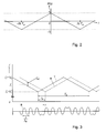
- Figure 3 shows beat signal characteristics. More specifically, Fig. 3 shows the relation between the transmitted signal T and the received signal R in terms of frequency difference f dif (upper part) and the resulting beat signal B (lower part). Because the transmitted signal is frequency modulated with a triangular waveform the delay t d between the transmitted and the received signal corresponds to a frequency difference between the transmitted and received signal.
- This angular frequency difference can easily be detected by multiplying the received signal by the transmitted signal, by means of the mixer 7.
- S M1 ( t ) contains the low frequencies while the spectrum of S M2 ( t ) contains the high frequencies around 2 ⁇ c .
- the latter term will be suppressed by filtering by the filter 8 and is not discussed further.
- the signal of interest is S M1 (t) :
- S M ⁇ 1 t 1 2 ⁇ A R ⁇ A T ⁇ cos ⁇ c ⁇ t d + ⁇ s ⁇ H t ⁇ t d
- the beat signal S M1 (t) has a frequency that is equal to the difference of the transmitted and received frequency (equation (4)) and hence the detection height h (equation (5)).
- S M1 (t) is periodic with T m .
- the frequency spectrum of S M1 (t) consists of harmonics with modulation frequency f m .
- Figure 4 shows an amplitude frequency spectrum A of a first beat signal.
- a n 1 2 ⁇ A R ⁇ A T ⁇ ⁇ s ⁇ t d 1 2 ⁇ ⁇ s ⁇ t d + 1 2 ⁇ n ⁇ ⁇ ⁇ 1 2 ⁇ ⁇ s ⁇ t d - 1 2 ⁇ n ⁇ ⁇ ⁇ cos ⁇ c ⁇ t d + 1 2 ⁇ n ⁇ ⁇ ⁇ sin 1 2 ⁇ ⁇ s ⁇ t d - 1 2 ⁇ n ⁇ ⁇ ⁇
- Equation (12) the amplitude coefficient a n of harmonic component n can be seen as a modulation function itself. So the coefficient a n can be divided into three parts:
- a n rad phase shift occurs in the harmonic signal. These phase shifts occur at regular intervals, except at the main lobe of the sinc function. This phenomenon can be used to detect the height.
- Fig. 7 shows that the second and fourth harmonic have a n rad phase difference above 60 meter and below 30 meter. Between 30 and 60 meter the second and fourth harmonic are in phase (both sinc parts are positive).
- the four phases ⁇ (a n ) of the first four harmonics may be computed. Then the differential phases ⁇ (a 2 )- ⁇ ( a 4 ) and ⁇ (a1) - ⁇ (a 3 ) can be computed.
- the behaviour of both differential phases ph diff as a function of height is shown in Fig. 8 .
- differential phase shifts fa 1 - f a 4 occur at four heights. Each of these differential phase shifts can be used as a height detection event.
- the height at the differential phase shift of ⁇ (a 2 )- ⁇ (a 4 ) can be determined.
- a pre-amble can be used: first a differential phase shift of ⁇ (a 1 )- ⁇ (a 3 ) must be detected before a differential phase shift of ⁇ (a 2 )- ⁇ (a 4 ) is expected to occur to perform a height detection when the height decreases in a substantially monotone manner, in a direction of flight F.
- phase information of further or other harmonics may be used, e.g. phase information of the fifth and sixth harmonic.
- the processing unit 6, more specifically the processor 9, is arranged for using phase shift information of at least one of said harmonics for determining a distance between the radar system and the reflecting surface.
- a differential phase shift is used as a height detection event.
- the height at which these events occur can be altered by changing the angular sweep frequency ⁇ s . This can be deducted from Equation (12) when analyzing the phase relationship between, for example, the harmonics a 2 and a 4 .
- both a 2 and a 4 are not in phase, see Fig. 7 .
- a 2 and a 4 are in phase.
- the phases of a 2 and a 4 are again opposite. I.e. the height to be detected is reached when a 2 reaches its peak.
- the detection height h can be changed by changing the angular sweep frequency ⁇ s . This can easily be implemented by using a voltage controlled oscillator to generate the sweep signal.
- any used hardware will exhibit some FM demodulation capability. Even in free space, with no objects present in the vicinity of the fuze hardware, the harmonics a n will have a given amplitude. This effect is caused by reflections of the transmitted signal at the antenna connection. The reflected signal is fed to the mixer, as any received signal would do. Due to the difference in path-length (between the "regular” path generator-mixer and the "spurious" path generator-antenna-mixer) FM detection will take place. The FM demodulation spurious will manifest itself as a strong target echo at (near) zero distance and zero velocity.
- the FM demodulation spurious is frequency dependent in amplitude and phase, making the exact FM demodulation effect very unpredictable and virtually impossible to compensate for.
- the spurious is free of Doppler, which enables it to be separated from the Earth's reflection.
- the spectrum of the receiver signal combined with FM demodulation spurious might look like the spectrum given in Fig. 9 showing an amplitude frequency spectrum of a second beat signal.
- a central signal 23 is caused by internal reflections at the transceiver while the offset signals 24 represent the Doppler shifted harmonic components.
- the input of the algorithm is a sampled and digitized beat signal. Before the actual height detection can be performed, it is advantageously first assured that the beat signal contains sufficient information. Therefore, in a first step, a signal-to-noise ratio (SNR) of a differential phase is determined and it is checked whether the SNR ratio exceeds a predetermined threshold value.
- SNR signal-to-noise ratio
- the sub-steps necessary to compute the differential phases ⁇ (a 1 ) - ⁇ ( ⁇ 3 ) and ⁇ ( ⁇ 2 ) - ⁇ (a 4 ) may include applying a filter bank to generate four real parts and four imaginary parts of the beat signal in base band, applying a zero Doppler remover, calculating the phase of the four complex signals, and computing differential phases.
- These sub-steps can be used for the SNR computation as well as for the height detection. In the following, the above-mentioned sub-steps are described in more detail.
- the filter bank has as input the sampled and digitized beat signal.
- the filter bank may be implemented using a cosine modulated filter bank which output consists of four complex signals representing the first four harmonics of the input signal.
- the complex output of the n th harmonic is computed by filtering the spectrum around the n th harmonic and simultaneously shifting the spectrum to the zero centre frequency. After filtering, the beat signal is separated in four real parts and four imaginary parts.
- the phase of the complex signal is computed. Then, the differential phases ⁇ (a 1 ) - ⁇ (a 3 ) and ⁇ (a 2 ) - ⁇ (a 4 ) are computed forming a basis for performing the detection.
- the received signal contains no or only a small portion of the reflected signal.
- the behaviour of the harmonic components a 1-4 is at least partially determined by the height: at large heights the harmonic components a 1-4 are small and dominated by noise. Hence also the phase difference is dominated by noise: the values of the differential phases ⁇ (a 1 ) - ⁇ (a 3 ) and ⁇ (a 2 ) - ⁇ (a 4 ) are more or less uniform distributed across 2 ⁇ rad at high altitudes.
- the reflected signal from the Earth's surface will gain in strength and hence the differential phases will start to be either 0 or n rad as is expected from analysing e.g. Fig. 8 .
- This phase will have an offset called the reference phase ⁇ ref .
- the amount of measurements at ⁇ ref and ⁇ ref + ⁇ is used as a measure for the Signal to Noise Ratio (SNR). Computation of the SNR is explained below.
- the inputs of the SNR computation are the differential phases.
- the differential phases range between 0 and 2 ⁇ rad.
- the calculated differential phases are distributed over K sets, i.e. for every measurement the value '1' is added to the set corresponding to the computed differential phase.
- a noise strength ( N ) is measured in the sets that do not contain the signal, i.e. all sets, excluding the reference set k and its n rad counterpart. The noise strength is averaged across these sets.
- a SNR ratio is determined, the signal strength is compared with the noise level. Sufficient SNR is assumed to be reached when the signal level exceeds the noise level by some amount, e.g. when the signal to noise ration exceeds a predetermined level.
- the detection part of the algorithm is started.
- the detection part of the algorithm may comprise a number of sub-steps.
- a reference phase can now be computed. Note that it is in general not possible to predict the value of the reference phase due to imperfections in the analogue electronics. All differential phases are corrected with the reference phase such that the resulting average phase difference is either 1 ⁇ 2 ⁇ rad or 1 1 ⁇ 2 ⁇ rad.
- both sets are low-pass filtered to reduce noise.
- the resulting signals called the gate signals, contain the 0 ⁇ 1 and 1 ⁇ 0 transitions related to the phase shifts as shown in Fig. 8 .
- both gate signals are fed into a state machine and are evaluated for the n rad phase shifts.
- the state machine starts when sufficient SNR is reached in SNR(13) and SNR(24).
- the argument 13 indicates the phase difference between the third and first harmonic while the argument 24 indicates the phase difference between the fourth and second harmonic.
- the gate signal of ⁇ (a2)- ⁇ (a4) must exceed a threshold. This check reduces the probability of false detections.
- the gate signal of ⁇ (a1)- ⁇ (a3) exceeds a threshold the state '24 and 13 open' is entered. This is a pre-amble for the actual height detection. A transition of the gate signal ⁇ (a2)- ⁇ (a4) results in the detection of the height.
- Simulations have been performed to validate the performance of the algorithm.
- a signal model is used that incorporates the speed of descent, surface reflection coefficient, surface scattering, FM demodulation spurious, noise and quantization effects.
- For each set detection height various signal are generated while taking into account the effects of the delay of the filter stages.
- Figures 10a-d show the behaviour of some internal signals as a function of height.
- Fig. 10a shows phase difference signals as a function of height, in particular all ⁇ (a 1 )- ⁇ (a 3 ) phases 25 and all ⁇ (a 2 )- ⁇ (a 4 ) phases 26 as a function of height.
- the phases are randomly distributed in the interval [0, 2 ⁇ ).
- the phases concentrate around two phases.
- the SNR is sufficient to start the detection algorithm.
- the phases in the top plot are shifted to the reference phase.
- Figures 10b-c show the gate signal for respectively the phase differences ⁇ (a 1 )- ⁇ (a 3 ) and ⁇ (a 2 )- ⁇ (a 4 ). These signals are the filtered versions of Fig. 10a . Both the filtered signal 28, 30 as well as the unfiltered signals 27, 29 have been shown. The fourth plot shows the internal state signal 31 of the algorithm. The states are:
- the simulations are repeated for various signals.
- the average deviation between set height and detected height is below 10% even under realistic conditions including low surface reflectivity, surface scattering, FM demodulation spurious, noise and quantization effects.
- a crane 35 carries a platform 36 containing the radar system with the transceiver module 37 and the processing unit 38. During the test, the platform 36 moves downwards to the Earth's surface 39 having a vertical velocity v v . Relevant parameters such as sweep frequency, sweep repetition rate and sample frequency are scaled to the actual descent speed of the crane. Therefore, the filters of the harmonic filter bank and the filter for the zero-Doppler remover were scaled to account for these differences.
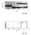
- the experiments cover two types of surface: flat meadowland and a wooded hill (about 3 meters height). Eight signals were recorded. Figures 12a-d show the behaviour of some internal signals as a function of height, similar to Fig. 10a-d .
- the detection height was set to be 10m.
- the average detection height was 9.15m with a standard deviation of 0.57m.
- FIG. 13 shows a flow chart of an embodiment of the method according to the invention.
- a method is used for detecting a distance between a radar system and a reflecting surface. The method comprises the steps of transmitting (100) a frequency modulated continuous wave (FMCW) radar signal from the radar system, receiving (110) a reflected FMCW radar signal being the transmitted signal that has been reflected by the reflecting surface, providing (120) a beat signal having a frequency that is equal to the frequency difference between the transmitted signal and the received signal, determining (130) harmonics of the beat signal, and using (140) phase shift information of at least one of said harmonics for determining a distance between the radar system and the reflecting surface.
- FMCW frequency modulated continuous wave
- the method for detecting a distance between a radar system and a reflecting surface can be performed using dedicated hardware structures, such as FPGA and/or ASIC components. Otherwise, the method can also at least partially be performed using a computer program product comprising instructions for causing a processing unit or a computer system to perform the above described steps of the method according to the invention. All processing steps can in principle be performed on a single processor. However it is noted that at least one step can be performed on a separate processor, e.g. the step of providing a beat signal and/or the step of determining harmonics of the beat signal.
- the method uses the phase information hidden in the harmonics of the signal resulting from mixing the transmitted and received signal. This makes the algorithm virtual independent of surface scatter, improves the accuracy and reduces the influences of noise. In addition, the optional application of a pre-amble gate improves the robustness against false detections.
- the algorithm may use a sophisticated method to detect whether the signal-to-noise ratio is sufficient to start the height detection. Advances in digital signal processing capabilities allow the implementation of this innovative algorithm in real-time.
- implementation on a digital signal platform allows changing the detection height without changes in the design. This is in contrast with discrete implementations where filters need to be adjusted to match the detection height.
Landscapes
- Engineering & Computer Science (AREA)
- Radar, Positioning & Navigation (AREA)
- Remote Sensing (AREA)
- Computer Networks & Wireless Communication (AREA)
- Physics & Mathematics (AREA)
- General Physics & Mathematics (AREA)
- General Engineering & Computer Science (AREA)
- Signal Processing (AREA)
- Radar Systems Or Details Thereof (AREA)
Abstract
The invention relates to a method for detecting a distance between a radar system and a reflecting surface. The method comprises the steps of transmitting a frequency modulated continuous wave (FMCW) radar signal from the radar system and receiving a reflected FMCW radar signal being the transmitted signal that has been reflected by the reflecting surface. Further, the method comprises the steps of providing a beat signal having a frequency that is equal to the frequency difference between the transmitted signal and the received signal and determining harmonics of the beat signal. The method also comprises the step of using phase shift information of at least one of said harmonics for determining a distance between the radar system and the reflecting surface.
Description
- The invention relates to a method for detecting a distance between a radar system and a reflecting surface, comprising the steps of transmitting a frequency modulated continuous wave (FMCW) radar signal from the radar system, receiving a reflected FMCW radar signal being the transmitted signal that has been reflected by the reflecting surface, providing a beat signal having a frequency that is equal to the frequency difference between the transmitted signal and the received signal and determining harmonics of the beat signal.
- Such methods are generally known, e.g. for detecting a height. Most contemporary algorithms for FMCW radar height detection measure the frequency difference of the transmitted and received signals. This frequency difference is linear dependent on the height: multiplying the transmitted by the received signal results in a beat signal with a frequency equal to the frequency difference between the transmitted and received signal.
- A standard approach to measure the frequency difference is to use a filter bank or a FFT. An analogue filter bank has the disadvantage that it is fixed at a limited number of frequencies (and thus height ranges) and that the slope of the filter has to be very steep to achieve accurate height detections. The later also holds for a digital filter bank. Applying a FFT requires the acquisition of a large number of samples, and hence introduces a delay that is equal or larger than the delay of a filter bank.
- A second approach is to use the amplitude relationships between harmonics of the beat signal. The amplitude, however, is not a robust measure for the height due to surface scattering. Especially, when the distance between the radar and the surface changes rapidly, there is usually not sufficient time to collect and average multiple measurements to reduce the noise in the harmonic's amplitudes.
- It is an object of the invention to provide a more accurate method according to the preamble for detecting a distance between a radar system and a reflecting surface. Thereto, the method according to the invention comprises also the step of using phase shift information of at least one of said harmonics for determining a distance between the radar system and the reflecting surface.
- The invention is partly based on the insight that, as a function of the distance between the radar system and the reflecting surface, phase shifts occur in the harmonics of the beat function. By using such phase shift information a specific distance between the radar system and the reflecting surface can be determined. It appears that this approach enhances the accuracy of the method considerably. Further, the method becomes virtually independent on the surface scatter type and reduces the influences of noise.
- Preferably, the step of using phase shift information comprises determining a phase difference between a pair of beat signal harmonics. By using phase difference information between a pair of harmonics, the insight is exploited that the phase shifts occur at regular intervals, except at the main lobe of a sinc function factor in the harmonics phase. When, in a certain application, the distance between the radar system and the reflecting surfaces reduces in a monotone manner, the phase difference between the pair of harmonics may remain constant, while a sudden shift in the phase difference occurs when a specific distance is reached, thereby enabling an accurate distance detection.
- In this context it is noted, that, in principle, also the absolute phase of a single harmonic can be monitored to check when a phase shift occurs. Such a phase shift can e.g. be determined by analyzing when the above-mentioned sinc function factor in the harmonics phase changes sign.
- By determining multiple phase differences, multiple distances can be determined. Specifically, when the method also comprises checking whether subsequent detected distances correspond with an expected distance evolution, e.g. when varying the distance between the radar system and the reflecting surface in a monotone manner, the robustness of the method improves, e.g. against false detections.
- In an advantageous embodiment according to the invention, the angular sweep frequency of the FMCW radar signal is set so as to allow a particular associated phase shift in a harmonic or between harmonics to correspond to a pre-determined distance between the radar system and the reflecting surface. As a result, a pre-set distance can be detected.
- Further, the invention relates to a radar system.
- Additionally, the invention relates to a computer program product. A computer program product may comprise a set of computer executable instructions stored on a data carrier, such as a CD or a DVD. The set of computer executable instructions, which allow a programmable computer to carry out the method as defined above, may also be available for downloading from a remote server, for example via the Internet.
- Other advantageous embodiments according to the invention are described in the following claims.
- By way of example only, embodiments of the present invention will now be described with reference to the accompanying figures in which
-
Fig. 1 shows a schematic view of a radar system according to the invention; -
Fig. 2 shows a triangular linear sweep signal; -
Fig. 3 shows beat signal characteristics; -
Fig. 4 shows an amplitude frequency spectrum of a first beat signal; -
Fig. 5 shows a diagram with an amplitude factor of an amplitude coefficient of beat signal harmonics; -
Fig. 6 shows a diagram with a sinc factor of an amplitude coefficient of beat signal harmonics; -
Fig. 7 shows a diagram with the product of the amplitude factor and the sinc factor shown inFigures 5 and6 ; -
Fig. 8 shows a diagram with a graph of differential phases as a function of height; -
Fig. 9 shows an amplitude frequency spectrum of a second beat signal; - Fig. l0a shows phase difference signals as a function of height;
-
Fig. 10b shows a second gate signal; -
Fig. 10c shows a first gate signal; -
Fig. 10d shows an internal state signal; -
Fig. 11 shows a schematic view of a test set-up; -
Fig. 12a shows validation phase difference signals as a function of height; -
Fig. 12b shows a second gate validation signal; -
Fig. 12c shows a first gate validation signal; -
Fig. 12d shows an internal state validation signal; -
Fig. 13 shows a flow chart of an embodiment of a method according to the invention. - The figures are merely schematic views of preferred embodiments according to the invention. In the figures, the same reference numbers refer to equal or corresponding parts.
-
Figure 1 shows a schematic view of aradar system 1 according to the invention. Theradar system 1 comprises a transmitter module arranged for transmitting a frequency modulated continuous wave (FMCW) radar signal T. Thesystem 1 also comprises a receiver module arranged for receiving a reflected FMCW radar signal R being the transmitted signal that has been reflected by the reflecting surface. The transmitter module and the receiver module have been integrated into asingle transceiver module 2 for both transmitting and receiving FMCW radar signals. Thetransceiver module 2 comprises anantenna element 3, agenerator 4 for generating the signal to be transmitted and asplitter 5 for splitting the transmitted radar signal T and the received radar signal R. It is noted that, as an alternative, the transmitter module and the receiver module can also be implemented as separate modules. - The
radar system 1 shown inFig. 1 further comprises aprocessing unit 6 that is arranged for performing a number of processing tasks. Theprocessing unit 6 includes amixer 7, a filter 8 and aprocessor 9 including an ADC unit for generating adigital output signal 10. Theradar system 1 according to the invention can typically be used for detecting their height while fast ascending or descending. Specific applications include altitude measurements in planes, ignition height detection in fuses or missiles, or altitude detection in space explorers. - During operation of the
radar system 1, thegenerator 4 produces a signal to be transmitted, which is frequency modulated, producing a triangular linear FM sweep. The signal is fed to theantenna element 3. The signal is transmitted by theantenna 3 as a transmitted signal T, reflected by a reflectingsurface 11, such as the Earth's surface, and received back by theantenna element 3 as a reflected signal R. Due to a distance, e.g. a height (h), between the radar system and a reflectingsurface 11, the signal will be attenuated and delayed. Due to the vertical velocity (vv ) of the FMCW radar transceiver, the signal will be affected by Doppler. The signal received by the antenna is fed to themixer 7 where it is multiplied by the transmitted signal to obtain a signal that has been mixed to base band. The resulting signal is fed to the filter-amplifier where it is low pass filtered. The amplified low frequency signal, called the beat signal, is converted to digital. - It is noted that in the shown embodiment, the radar system is arranged for detecting a height above the Earth's
surface 11. However, the radar system can in principle also be applied for detecting another distance type, e.g. a horizontal offset between the radar system and a reflecting wall. - The detection principle uses a triangular modulated FMCW signal.
Figure 2 shows a triangular linear sweep H(t) being defined as:
where Tm denotes the periodicity of the triangular modulation [s] and t denotes time. The transmitted signal can be described as:
AT : The transmitted RF amplitude
ω c : Angular centre frequency of fc [rad/s]
ωs : Angular sweep frequency of fs [rad/s] - The transmitted signal is reflected by the Earth's surface and will reach the FMCW radar transceiver with a delay proportional to the height:

td : Delay time [s]
h : Height of the FMCW radar transceiver [m]
c : Speed of light [m/s] - The received signal is the delayed version of the transmitted signal:

where AR denotes the received RF amplitude. -
Figure 3 shows beat signal characteristics. More specifically,Fig. 3 shows the relation between the transmitted signal T and the received signal R in terms of frequency difference fdif (upper part) and the resulting beat signal B (lower part). Because the transmitted signal is frequency modulated with a triangular waveform the delay td between the transmitted and the received signal corresponds to a frequency difference between the transmitted and received signal. The angular difference frequency is equal to:
- The combination of Equations (2) and (4) yields:

which gives a direct relation between the detection height h and the measured angular frequency difference ω dif . This angular frequency difference can easily be detected by multiplying the received signal by the transmitted signal, by means of themixer 7.
- At low altitudes td << Tm it can be assumed that H(t) is constant within the time interval [t-td , t] and hence H(t) equals H(t-td). The equation becomes:

- The spectrum of SM1 (t) contains the low frequencies while the spectrum of SM2 (t) contains the high frequencies around 2ω c . The latter term will be suppressed by filtering by the filter 8 and is not discussed further. The signal of interest is SM1(t):

- Substituting H(t) results into:

- The beat signal SM1(t) has a frequency that is equal to the difference of the transmitted and received frequency (equation (4)) and hence the detection height h (equation (5)).
- Since H(t) is periodic with Tm also SM1(t) is periodic with Tm . The frequency spectrum of SM1(t) consists of harmonics with modulation frequency fm .
Figure 4 shows an amplitude frequency spectrum A of a first beat signal. The signal SM1(t) can therefore be described with:
where:

n denotes an index of harmonic component. - Therefore, the
processing unit 6 performs the step of providing a beat signal having a frequency that is equal to the frequency difference between the transmitted signal and the received signal, and the step of determining harmonics of the beat signal. Because SM1(t) = SM1(-t) all bn components are zero. The amplitude coefficient of the harmonics components an can be written as:
- AR is also a function of the height h:

where:
λ c : Wavelength of the transmitter central frequency [m]
C : Constant, depending on hardware properties - Equation (10) can be re-written as:

- It is shown in Equation (12) that the amplitude coefficient an of harmonic component n can be seen as a modulation function itself. So the coefficient an can be divided into three parts:
- Amplitude
The first part of the coefficient can be interpreted as amplitude. This amplitude part A' is shown inFig. 5 . Here, the amplitude factor is shown as agraph 20a-f for n=1 (fundamental) to n=6, respectively, as a function of the height h. - Sinc function
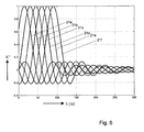
The sinc function (sin (x)/x) giving a peak for a given delay and hence a given height, as is shown inFig. 6 showing a sinc factor A" of an amplitude coefficient of beat signal harmonics as a function of the height h. Again, thegraph 21a-f corresponds to the harmonics order n=1, ..., 6, respectively. - Harmonic carrier
The presence of the harmonic carrier is due to the fact that a standing wave pattern will develop between the FMCW radar transceiver and the ground. When the FMCW radar transceiver moves to the ground a half wavelength (of the transmitter centre frequency), the amplitude of an moves from maximum to minimum and vice versa. This carrier frequency can alternatively be interpreted as the Doppler frequency that is generated when the FMCW radar transceiver moves towards the ground.
The amplitude and sinc part of function an can be combined, which result in thegraphs 22a-f corresponding to the harmonics order n=1,...,6, respectively, shown inFig. 7 showing the product A"' of the amplitude factor and the sinc factor shown inFig. 5 and6 . It is clear that each harmonic component peaks at a given height and that other harmonics are zero at that height. For example, at 45 meter a3 is maximum, where a1 and a5 are zero. This fact can be used to detect a given height. - When the amplitude of the sinc part, as shown in
Fig. 7 , changes sign, a n rad phase shift occurs in the harmonic signal. These phase shifts occur at regular intervals, except at the main lobe of the sinc function. This phenomenon can be used to detect the height. For example,Fig. 7 shows that the second and fourth harmonic have a n rad phase difference above 60 meter and below 30 meter. Between 30 and 60 meter the second and fourth harmonic are in phase (both sinc parts are positive). The first (=fundamental) and third harmonic have a phase difference of n rad above 45 meter and below 15 meter. Between 15 and 45 meter the first and third harmonic are in phase. - During operation of the radar system, the four phases ϕ(an) of the first four harmonics may be computed. Then the differential phases ϕ(a2)-ϕ(a 4) and ϕ(a1)- ϕ(a3) can be computed. The behaviour of both differential phases phdiff as a function of height is shown in
Fig. 8 . As can be seen, differential phase shifts fa1 - fa4 occur at four heights. Each of these differential phase shifts can be used as a height detection event. Using the differential phase shift information, the height at the differential phase shift of ϕ(a2)- ϕ(a4) can be determined. To increase the robustness against false detections a pre-amble can be used: first a differential phase shift of ϕ(a1)-ϕ(a3) must be detected before a differential phase shift of ϕ(a2)- ϕ(a4) is expected to occur to perform a height detection when the height decreases in a substantially monotone manner, in a direction of flight F. In this context it is noted that also phase information of further or other harmonics may be used, e.g. phase information of the fifth and sixth harmonic. - Thus, the
processing unit 6, more specifically theprocessor 9, is arranged for using phase shift information of at least one of said harmonics for determining a distance between the radar system and the reflecting surface. - As mentioned above, a differential phase shift is used as a height detection event. The height at which these events occur can be altered by changing the angular sweep frequency ω s . This can be deducted from Equation (12) when analyzing the phase relationship between, for example, the harmonics a2 and a4 .
- During descent, before a4 reaches its peak, both a2 and a4 are not in phase, see
Fig. 7 . Between the peaks of a2 and a4 , a2 and a4 are in phase. After a2 reaches its peak, the phases of a2 and a4 are again opposite. I.e. the height to be detected is reached when a2 reaches its peak. Equation (12) for a2 yields:
- The harmonic a2 reaches its peak when:

In conclusion: the detection height h can be changed by changing the angular sweep frequency ω s . This can easily be implemented by using a voltage controlled oscillator to generate the sweep signal. - Any used hardware will exhibit some FM demodulation capability. Even in free space, with no objects present in the vicinity of the fuze hardware, the harmonics an will have a given amplitude. This effect is caused by reflections of the transmitted signal at the antenna connection. The reflected signal is fed to the mixer, as any received signal would do. Due to the difference in path-length (between the "regular" path generator-mixer and the "spurious" path generator-antenna-mixer) FM detection will take place. The FM demodulation spurious will manifest itself as a strong target echo at (near) zero distance and zero velocity. The effect of spurious can be taken into account by:

where FMspurious,n is a constant value representing the nth harmonic of FM demodulation spurious. - The FM demodulation spurious is frequency dependent in amplitude and phase, making the exact FM demodulation effect very unpredictable and virtually impossible to compensate for. However, the spurious is free of Doppler, which enables it to be separated from the Earth's reflection. The spectrum of the receiver signal combined with FM demodulation spurious might look like the spectrum given in
Fig. 9 showing an amplitude frequency spectrum of a second beat signal. Acentral signal 23 is caused by internal reflections at the transceiver while the offset signals 24 represent the Doppler shifted harmonic components. - Below, an implementation of a specific algorithm is described in detail. Other implementations are also possible. The input of the algorithm is a sampled and digitized beat signal. Before the actual height detection can be performed, it is advantageously first assured that the beat signal contains sufficient information. Therefore, in a first step, a signal-to-noise ratio (SNR) of a differential phase is determined and it is checked whether the SNR ratio exceeds a predetermined threshold value.
- The sub-steps necessary to compute the differential phases ϕ(a1) - ϕ(α3) and ϕ(α2) - ϕ(a4) may include applying a filter bank to generate four real parts and four imaginary parts of the beat signal in base band, applying a zero Doppler remover, calculating the phase of the four complex signals, and computing differential phases. These sub-steps can be used for the SNR computation as well as for the height detection. In the following, the above-mentioned sub-steps are described in more detail.
- The filter bank has as input the sampled and digitized beat signal. The filter bank may be implemented using a cosine modulated filter bank which output consists of four complex signals representing the first four harmonics of the input signal. The complex output of the nth harmonic is computed by filtering the spectrum around the nth harmonic and simultaneously shifting the spectrum to the zero centre frequency. After filtering, the beat signal is separated in four real parts and four imaginary parts.
- Due to the FM demodulation spurious there is a large DC component (the zero Doppler) present at all outputs of the filter bank. This component is removed by applying a high pass filter. This filter is applied to the four real parts and to the four imaginary parts resulting in eight zero-Doppler removers (filters).
- In a next sub-step, for all four harmonic components the phase of the complex signal is computed. Then, the differential phases ϕ(a1) - ϕ(a3) and ϕ(a2) - ϕ(a4) are computed forming a basis for performing the detection.
- At high altitudes, the received signal contains no or only a small portion of the reflected signal. The behaviour of the harmonic components a1-4 is at least partially determined by the height: at large heights the harmonic components a1-4 are small and dominated by noise. Hence also the phase difference is dominated by noise: the values of the differential phases ϕ(a1) - ϕ(a3) and ϕ(a2) - ϕ(a4) are more or less uniform distributed across 2π rad at high altitudes. When descending with the radar system, the reflected signal from the Earth's surface will gain in strength and hence the differential phases will start to be either 0 or n rad as is expected from analysing e.g.
Fig. 8 . This phase however will have an offset called the reference phase ϕ ref . The amount of measurements at ϕ ref and ϕ ref + π is used as a measure for the Signal to Noise Ratio (SNR). Computation of the SNR is explained below. - The inputs of the SNR computation are the differential phases. The differential phases range between 0 and 2π rad. To determine the SNR, the calculated differential phases are distributed over K sets, i.e. for every measurement the value '1' is added to the set corresponding to the computed differential phase.
- After classification, all K sets are low-pass filtered to reduce noise. Based on the results of filtering, the signal strength is computed. The set k ∈ K with the highest value is considered to be the reference set and the value of this set is considered to be A signal strength (S). A noise strength (N) is measured in the sets that do not contain the signal, i.e. all sets, excluding the reference set k and its n rad counterpart. The noise strength is averaged across these sets.
- When the signal strength S and the noise strength N have been measured, a SNR ratio is determined, the signal strength is compared with the noise level. Sufficient SNR is assumed to be reached when the signal level exceeds the noise level by some amount, e.g. when the signal to noise ration exceeds a predetermined level.
- When the SNR is sufficient, the detection part of the algorithm is started. The detection part of the algorithm may comprise a number of sub-steps.
- In a first sub-step, a reference phase can now be computed. Note that it is in general not possible to predict the value of the reference phase due to imperfections in the analogue electronics. All differential phases are corrected with the reference phase such that the resulting average phase difference is either ½π rad or 1 ½π rad.
- In a second sub-step, all shifted differential phases are classified into one of the sets [0, π) and [π, 2 n).
- In a third sub-step, after classification, both sets are low-pass filtered to reduce noise. The resulting signals, called the gate signals, contain the 0 → 1 and 1 → 0 transitions related to the phase shifts as shown in
Fig. 8 . - In a fourth sub-step, both gate signals are fed into a state machine and are evaluated for the n rad phase shifts. The state machine starts when sufficient SNR is reached in SNR(13) and SNR(24). The
argument 13 indicates the phase difference between the third and first harmonic while theargument 24 indicates the phase difference between the fourth and second harmonic. Before transitioning to a next state, first the gate signal of ϕ(a2)- ϕ(a4) must exceed a threshold. This check reduces the probability of false detections. When also the gate signal of ϕ(a1)- ϕ(a3) exceeds a threshold the state '24 and 13 open' is entered. This is a pre-amble for the actual height detection. A transition of the gate signal ϕ(a2)- ϕ(a4) results in the detection of the height. - Simulations have been performed to validate the performance of the algorithm. A signal model is used that incorporates the speed of descent, surface reflection coefficient, surface scattering, FM demodulation spurious, noise and quantization effects. For each set detection height various signal are generated while taking into account the effects of the delay of the filter stages.
-
Figures 10a-d show the behaviour of some internal signals as a function of height. Specifically,Fig. 10a shows phase difference signals as a function of height, in particular all ϕ(a1)- ϕ(a3) phases 25 and all ϕ(a2)- ϕ(a4) phases 26 as a function of height. At larger heights (at the left) the phases are randomly distributed in the interval [0, 2π). During descent the phases concentrate around two phases. At that point the SNR is sufficient to start the detection algorithm. At the moment sufficient SNR is reached the phases in the top plot are shifted to the reference phase.Figures 10b-c show the gate signal for respectively the phase differences ϕ(a1)- ϕ(a3) and ϕ(a2)- ϕ(a4). These signals are the filtered versions ofFig. 10a . Both the filteredsignal unfiltered signals internal state signal 31 of the algorithm. The states are: - initial: start of the algorithm
- SNR OK: the phase difference ϕ(a1)-ϕ(a3) or the phase difference ϕ(a2)-ϕ(a4) has reached sufficient SNR.
- SNRs OK: both phase differences have reached sufficient SNR.
- 24 open: 0 → 1 transition of a firstgate signal ϕ(a2)- ϕ(a4).
- 24 and 13 open: 0 → 1 transition of a second gate signal ϕ(a1)- ϕ(a3).
- ignite: 1 → 0 transition of the gate signal ϕ(a2)- ϕ(a4).
- The simulations are repeated for various signals. The average deviation between set height and detected height is below 10% even under realistic conditions including low surface reflectivity, surface scattering, FM demodulation spurious, noise and quantization effects.
- Validation have been performed to validate the performance of the algorithm with real signals. These signals have been recorded with experimental electronics performing a descent using a large hoist crane, see
Fig. 11 showing a schematic view of a test set-up. Here, acrane 35 carries aplatform 36 containing the radar system with thetransceiver module 37 and theprocessing unit 38. During the test, theplatform 36 moves downwards to the Earth'ssurface 39 having a vertical velocity vv . Relevant parameters such as sweep frequency, sweep repetition rate and sample frequency are scaled to the actual descent speed of the crane. Therefore, the filters of the harmonic filter bank and the filter for the zero-Doppler remover were scaled to account for these differences. The experiments cover two types of surface: flat meadowland and a wooded hill (about 3 meters height). Eight signals were recorded.Figures 12a-d show the behaviour of some internal signals as a function of height, similar toFig. 10a-d . The detection height was set to be 10m. The average detection height was 9.15m with a standard deviation of 0.57m. -
Figure 13 shows a flow chart of an embodiment of the method according to the invention. A method is used for detecting a distance between a radar system and a reflecting surface. The method comprises the steps of transmitting (100) a frequency modulated continuous wave (FMCW) radar signal from the radar system, receiving (110) a reflected FMCW radar signal being the transmitted signal that has been reflected by the reflecting surface, providing (120) a beat signal having a frequency that is equal to the frequency difference between the transmitted signal and the received signal, determining (130) harmonics of the beat signal, and using (140) phase shift information of at least one of said harmonics for determining a distance between the radar system and the reflecting surface. - The method for detecting a distance between a radar system and a reflecting surface can be performed using dedicated hardware structures, such as FPGA and/or ASIC components. Otherwise, the method can also at least partially be performed using a computer program product comprising instructions for causing a processing unit or a computer system to perform the above described steps of the method according to the invention. All processing steps can in principle be performed on a single processor. However it is noted that at least one step can be performed on a separate processor, e.g. the step of providing a beat signal and/or the step of determining harmonics of the beat signal.
- The method uses the phase information hidden in the harmonics of the signal resulting from mixing the transmitted and received signal. This makes the algorithm virtual independent of surface scatter, improves the accuracy and reduces the influences of noise. In addition, the optional application of a pre-amble gate improves the robustness against false detections. Prior to the detection of the height, the algorithm may use a sophisticated method to detect whether the signal-to-noise ratio is sufficient to start the height detection. Advances in digital signal processing capabilities allow the implementation of this innovative algorithm in real-time. In addition, implementation on a digital signal platform allows changing the detection height without changes in the design. This is in contrast with discrete implementations where filters need to be adjusted to match the detection height.
- The performance of the method has been verified using simulation. A signal model was used that incorporates the speed of descent, the surface reflection coefficient, the surface scatter angle, FM demodulation spurious, noise and quantization effects. The simulation results show that the algorithm, despite the introduced distortions, performs very well. The maximum deviation from the set height was always below 10%.
- To validate the new algorithm, an experimental radar system has been build. Using a hoist crane descends were performed. The results of the algorithm were comparable with the simulations: the maximum deviation from the set height was always below 10%.
- Applications of this new algorithm can be found in among others avionics, military and space applications.
- The invention is not restricted to the embodiments described herein. It will be understood that many variants are possible.
- Other such variants will be obvious for the person skilled in the art and are considered to lie within the scope of the invention as formulated in the following claims.
Claims (10)
- A method for detecting a distance between a radar system and a reflecting surface, comprising the steps of:- transmitting a frequency modulated continuous wave (FMCW) radar signal from the radar system;- receiving a reflected FMCW radar signal being the transmitted signal that has been reflected by the reflecting surface;- providing a beat signal having a frequency that is equal to the frequency difference between the transmitted signal and the received signal;- determining harmonics of the beat signal; and- using phase shift information of at least one of said harmonics for determining a distance between the radar system and the reflecting surface.
- A method according to claim 1, wherein the step of using phase shift information comprises determining a phase difference between a pair of harmonics.
- A method according to claim 2, wherein the step of using phase shift information comprises determining multiple phase differences.
- A method according to any of the previous claims, further comprising setting an angular sweep frequency so as to allow a particular associated phase shift in a harmonic or between harmonics to correspond to a pre-determined distance between the radar system and the reflecting surface.
- A method according to any of the previous claims, further comprising checking whether subsequent detected distances correspond with an expected distance evolution.
- A method according to any of the previous claims, further comprising checking a signal to noise ratio of the phase shift information prior to detecting a height.
- A method according to any of the previous claims, wherein a height detection is started when the signal to noise ratio of the phase shift information exceeds a predetermined level.
- A method according to any of the previous claims, wherein a signal to noise ratio of the phase shift information is determined by distributing calculated differential phases over K sets, low-pass filtering the K sets, selecting a reference set having a highest value for computing a signal strength, and computing a noise strength measured in the sets.
- A radar system for detecting a distance to a reflecting surface, comprising:- a transmitter module arranged for transmitting a frequency modulated continuous wave (FMCW) radar signal;- receiver module arranged for receiving a reflected FMCW radar signal being the transmitted signal that has been reflected by the reflecting surface; and a processing unit arranged for:- providing a beat signal having a frequency that is equal to the frequency difference between the transmitted signal and the received signal;- determining harmonics of the beat signal; and- using phase shift information of at least one of said harmonics for determining a distance between the radar system and the reflecting surface.
- A computer program product for detecting a distance between a radar system and a reflecting surface, which computer program product comprises instructions for causing a processing unit to perform the steps of:- providing a beat signal having a frequency that is equal to the frequency difference between a frequency modulated continuous waves (FMCW) radar signal being transmitted by the radar system and a received FMCW radar signal being the transmitted signal that has been reflected by the reflecting surface ;- determining harmonics of the beat signal; and- using phase shift information of at least one of said harmonics for determining a distance between the radar system and the reflecting surface.
Priority Applications (5)
| Application Number | Priority Date | Filing Date | Title |
|---|---|---|---|
| EP20090163020 EP2267477A1 (en) | 2009-06-17 | 2009-06-17 | A method for detecting a distance, a radar system and a computer program product |
| PCT/NL2010/050375 WO2010147469A1 (en) | 2009-06-17 | 2010-06-17 | A method for detecting a distance, a radar system and a computer program product |
| US13/379,098 US9310476B2 (en) | 2009-06-17 | 2010-06-17 | Method for detecting a distance, a radar system and a computer program product |
| EP10728415.0A EP2443474B1 (en) | 2009-06-17 | 2010-06-17 | A method for detecting a distance, a radar system and a computer program product |
| ES10728415.0T ES2634430T3 (en) | 2009-06-17 | 2010-06-17 | A method to detect a distance, a radar system and a computer program product |
Applications Claiming Priority (1)
| Application Number | Priority Date | Filing Date | Title |
|---|---|---|---|
| EP20090163020 EP2267477A1 (en) | 2009-06-17 | 2009-06-17 | A method for detecting a distance, a radar system and a computer program product |
Publications (1)
| Publication Number | Publication Date |
|---|---|
| EP2267477A1 true EP2267477A1 (en) | 2010-12-29 |
Family
ID=41078257
Family Applications (2)
| Application Number | Title | Priority Date | Filing Date |
|---|---|---|---|
| EP20090163020 Withdrawn EP2267477A1 (en) | 2009-06-17 | 2009-06-17 | A method for detecting a distance, a radar system and a computer program product |
| EP10728415.0A Active EP2443474B1 (en) | 2009-06-17 | 2010-06-17 | A method for detecting a distance, a radar system and a computer program product |
Family Applications After (1)
| Application Number | Title | Priority Date | Filing Date |
|---|---|---|---|
| EP10728415.0A Active EP2443474B1 (en) | 2009-06-17 | 2010-06-17 | A method for detecting a distance, a radar system and a computer program product |
Country Status (4)
| Country | Link |
|---|---|
| US (1) | US9310476B2 (en) |
| EP (2) | EP2267477A1 (en) |
| ES (1) | ES2634430T3 (en) |
| WO (1) | WO2010147469A1 (en) |
Cited By (3)
| Publication number | Priority date | Publication date | Assignee | Title |
|---|---|---|---|---|
| FR3014562A1 (en) * | 2013-12-10 | 2015-06-12 | Airbus Operations Sas | SYSTEM FOR MEASURING THE HEIGHT OF AN AIRCRAFT |
| CN106017610A (en) * | 2015-03-27 | 2016-10-12 | Vega格里沙贝两合公司 | Radar fill level measurement device comprising integrated limit level sensor |
| CN115575900A (en) * | 2022-10-17 | 2023-01-06 | 浙江大学 | A low-power fully differential multi-harmonic IQ zero-IF frequency mixing circuit |
Families Citing this family (10)
| Publication number | Priority date | Publication date | Assignee | Title |
|---|---|---|---|---|
| ITRM20130120A1 (en) * | 2013-02-28 | 2014-08-29 | Mbda italia spa | RADAR PROXIMITY SPOOL AND METHOD OF PROCESSING AN ECO RADAR SIGNAL FOR THE ACQUISITION OF DISTANCE INFORMATION BETWEEN A TARGET AND A DOPPLER RADAR |
| EP3243086A4 (en) * | 2015-01-08 | 2018-09-05 | Sysmetric Ltd. | Emcw layer thickness measurement apparatus and method |
| JP7261302B2 (en) * | 2019-08-07 | 2023-04-19 | 日立Astemo株式会社 | radar equipment |
| CN111190154B (en) * | 2019-09-24 | 2024-04-30 | 纵目科技(上海)股份有限公司 | Auxiliary driving system and method capable of inhibiting radar close-range harmonic waves |
| CN111175714B (en) * | 2019-09-24 | 2024-04-19 | 纵目科技(上海)股份有限公司 | Auxiliary driving method capable of suppressing radar close-range harmonic wave and storage medium |
| CN111190155B (en) * | 2019-09-24 | 2024-04-19 | 纵目科技(上海)股份有限公司 | Driving assistance system that suppresses radar harmonics at close range |
| CN111175716B (en) * | 2019-09-24 | 2024-04-19 | 纵目科技(上海)股份有限公司 | Auxiliary driving method capable of inhibiting radar close-range harmonic wave |
| KR102212489B1 (en) * | 2020-08-31 | 2021-02-04 | 주식회사 뉴이스트원테크 | Method for measuring distance using radar phase unwrapping, and method for preventing fall-down, and monitoring apparatus |
| CN114690171B (en) * | 2020-12-31 | 2025-09-05 | 上海禾赛科技有限公司 | Method for detection using frequency modulated continuous wave and laser radar |
| EP4071586A1 (en) * | 2021-04-09 | 2022-10-12 | Fresenius Medical Care Deutschland GmbH | Contactless operation of medical appliances |
Citations (5)
| Publication number | Priority date | Publication date | Assignee | Title |
|---|---|---|---|---|
| US2453169A (en) * | 1943-04-10 | 1948-11-09 | Sperry Corp | Radio ground clearance indicator |
| GB862059A (en) * | 1958-05-27 | 1961-03-01 | Nat Res Dev | Improvements in or relating to radar systems |
| US3149330A (en) * | 1958-12-01 | 1964-09-15 | Marconi Co Ltd | Frequency modulated doppler radar system |
| US3226717A (en) * | 1961-09-19 | 1965-12-28 | Litton Systems Inc | Fm-cw radar altimeter apparatus |
| US3872475A (en) * | 1971-12-31 | 1975-03-18 | Toyota Motor Co Ltd | Method and apparatus for measuring distance to moving target |
Family Cites Families (14)
| Publication number | Priority date | Publication date | Assignee | Title |
|---|---|---|---|---|
| US3026515A (en) * | 1956-09-21 | 1962-03-20 | Bloom Leonard | Frequency modulated radar |
| GB869809A (en) * | 1959-10-05 | 1961-06-07 | Marconi Wireless Telegraph Co | Improvements in or relating to radar systems |
| US4660040A (en) | 1985-07-08 | 1987-04-21 | Magnavox Government And Industrial Electronics Company | Target range sensing apparatus |
| US4856893A (en) * | 1987-09-30 | 1989-08-15 | Eaton Corporation | Laser distance measuring method and apparatus |
| GB8919963D0 (en) | 1989-09-04 | 1990-01-04 | Marconi Co Ltd | Intruder alarm system |
| US5343404A (en) * | 1992-11-12 | 1994-08-30 | Maritec Corp. | Precision digital multimeter and waveform synthesizer for multi-signals with distorted waveforms embedded in noise |
| JP3550829B2 (en) * | 1995-01-24 | 2004-08-04 | 株式会社デンソー | FM-CW radar device |
| US5826216A (en) * | 1997-02-07 | 1998-10-20 | Hittite Microwave Corp. | Anticipatory collision sensor system |
| SE519095C2 (en) | 1997-02-28 | 2003-01-14 | Saab Dynamics Ab | Method and apparatus for spacing by electromagnetic waves |
| JP3726441B2 (en) * | 1997-03-18 | 2005-12-14 | 株式会社デンソー | Radar equipment |
| US6834591B2 (en) | 1998-12-23 | 2004-12-28 | Bae Systems Plc | Proximity fuze |
| WO2000073818A1 (en) * | 1999-05-26 | 2000-12-07 | Robert Bosch Gmbh | Object detection system |
| FR2809186B1 (en) | 2000-05-22 | 2002-07-12 | Celine Corbrion | METHOD AND DEVICE FOR MEASURING THE SPEED OF A MOBILE |
| RU2255352C2 (en) | 2003-07-07 | 2005-06-27 | Кошуринов Евгений Иванович | Method and system for radar measurement of object speeds and coordinates (modifications) |
-
2009
- 2009-06-17 EP EP20090163020 patent/EP2267477A1/en not_active Withdrawn
-
2010
- 2010-06-17 US US13/379,098 patent/US9310476B2/en active Active
- 2010-06-17 ES ES10728415.0T patent/ES2634430T3/en active Active
- 2010-06-17 EP EP10728415.0A patent/EP2443474B1/en active Active
- 2010-06-17 WO PCT/NL2010/050375 patent/WO2010147469A1/en not_active Ceased
Patent Citations (5)
| Publication number | Priority date | Publication date | Assignee | Title |
|---|---|---|---|---|
| US2453169A (en) * | 1943-04-10 | 1948-11-09 | Sperry Corp | Radio ground clearance indicator |
| GB862059A (en) * | 1958-05-27 | 1961-03-01 | Nat Res Dev | Improvements in or relating to radar systems |
| US3149330A (en) * | 1958-12-01 | 1964-09-15 | Marconi Co Ltd | Frequency modulated doppler radar system |
| US3226717A (en) * | 1961-09-19 | 1965-12-28 | Litton Systems Inc | Fm-cw radar altimeter apparatus |
| US3872475A (en) * | 1971-12-31 | 1975-03-18 | Toyota Motor Co Ltd | Method and apparatus for measuring distance to moving target |
Non-Patent Citations (1)
| Title |
|---|
| MERRILL SKOLNIK: "Introduction to Radar Systems", part Section 3.3 1980, MCGRAW-HILL BOOK COMPANY, Singapore, ISBN: 0070579091, article "Frequency-Modulated CW Radar", pages: 81 - 92, XP002548186 * |
Cited By (3)
| Publication number | Priority date | Publication date | Assignee | Title |
|---|---|---|---|---|
| FR3014562A1 (en) * | 2013-12-10 | 2015-06-12 | Airbus Operations Sas | SYSTEM FOR MEASURING THE HEIGHT OF AN AIRCRAFT |
| CN106017610A (en) * | 2015-03-27 | 2016-10-12 | Vega格里沙贝两合公司 | Radar fill level measurement device comprising integrated limit level sensor |
| CN115575900A (en) * | 2022-10-17 | 2023-01-06 | 浙江大学 | A low-power fully differential multi-harmonic IQ zero-IF frequency mixing circuit |
Also Published As
| Publication number | Publication date |
|---|---|
| WO2010147469A1 (en) | 2010-12-23 |
| EP2443474B1 (en) | 2017-05-10 |
| EP2443474A1 (en) | 2012-04-25 |
| ES2634430T3 (en) | 2017-09-27 |
| US20120169529A1 (en) | 2012-07-05 |
| US9310476B2 (en) | 2016-04-12 |
Similar Documents
| Publication | Publication Date | Title |
|---|---|---|
| EP2443474B1 (en) | A method for detecting a distance, a radar system and a computer program product | |
| JP6903743B2 (en) | How to process signals from coherent riders and related rider systems | |
| EP3436845B1 (en) | Direct detection lidar system and method with frequency modulation (fm) transmitter and quadrature receiver | |
| RU2419813C2 (en) | Method and device for measuring distance | |
| US10564268B2 (en) | Phase-error correction in a synthetic aperture imaging system with local oscillator time delay adjustment | |
| TWI652495B (en) | A method of operating a laser detection and ranging (LADAR) system comprising non-transitory machine readable media objects storing executable instructions, and laser detection and ranging devices | |
| US6396436B1 (en) | Radar method for measuring distances between and relative speeds of a vehicle and one or more obstacles | |
| JP6935506B2 (en) | How to process signals from coherent riders to reduce noise and related rider systems | |
| JP2017026604A (en) | Radar system | |
| CN105487067A (en) | Coarse measurement and fine measurement distance signal processing method, processing module and chirp modulation photon counting laser radar system based on the module | |
| Rajkumar et al. | Design and development of dsp interfaces and algorithm for fmcw radar altimeter | |
| EP4273577A1 (en) | Detection method using frequency modulated continuous wave and lidar | |
| CN104111450A (en) | Method and system for detecting object micro Doppler characteristics by use of double pulses | |
| CN102147461B (en) | Observation signal processing apparatus | |
| RU2578041C1 (en) | Method of determining parameters of chirp signals | |
| CN113820672A (en) | System parameter design and simulation method for multi-mode microwave remote sensor spectrometer mode | |
| Hill et al. | Fiber-based 1.5 μm lidar vibrometer in pulsed and continuous modes | |
| RU2510663C2 (en) | Radar-tracking method of measurement of range of moving object | |
| JP3415472B2 (en) | Radio altimeter | |
| EP0965053B1 (en) | Method and device for determining distances | |
| Reinisch et al. | Precise radar range measurements with digisondes | |
| KR102836607B1 (en) | Improving range resolution method by extending FMCW radar signal | |
| CA3034765C (en) | Method for processing a signal arising from coherent lidar and associated lidar system | |
| CN117008074A (en) | Narrow-band multi-objective translation parameter estimation method based on product high-order fuzzy function | |
| Bhise et al. | Implementation of FMCW RADAR using FPGA |
Legal Events
| Date | Code | Title | Description |
|---|---|---|---|
| PUAI | Public reference made under article 153(3) epc to a published international application that has entered the european phase |
Free format text: ORIGINAL CODE: 0009012 |
|
| AK | Designated contracting states |
Kind code of ref document: A1 Designated state(s): AT BE BG CH CY CZ DE DK EE ES FI FR GB GR HR HU IE IS IT LI LT LU LV MC MK MT NL NO PL PT RO SE SI SK TR |
|
| AX | Request for extension of the european patent |
Extension state: AL BA RS |
|
| STAA | Information on the status of an ep patent application or granted ep patent |
Free format text: STATUS: THE APPLICATION IS DEEMED TO BE WITHDRAWN |
|
| 18D | Application deemed to be withdrawn |
Effective date: 20110630 |