EP2267392A1 - Heat exchanger - Google Patents
Heat exchanger Download PDFInfo
- Publication number
- EP2267392A1 EP2267392A1 EP09722156A EP09722156A EP2267392A1 EP 2267392 A1 EP2267392 A1 EP 2267392A1 EP 09722156 A EP09722156 A EP 09722156A EP 09722156 A EP09722156 A EP 09722156A EP 2267392 A1 EP2267392 A1 EP 2267392A1
- Authority
- EP
- European Patent Office
- Prior art keywords
- refrigerant
- heat exchanger
- heat transfer
- transfer tubes
- relationship
- Prior art date
- Legal status (The legal status is an assumption and is not a legal conclusion. Google has not performed a legal analysis and makes no representation as to the accuracy of the status listed.)
- Withdrawn
Links
Images



Classifications
-
- F—MECHANICAL ENGINEERING; LIGHTING; HEATING; WEAPONS; BLASTING
- F28—HEAT EXCHANGE IN GENERAL
- F28F—DETAILS OF HEAT-EXCHANGE AND HEAT-TRANSFER APPARATUS, OF GENERAL APPLICATION
- F28F1/00—Tubular elements; Assemblies of tubular elements
- F28F1/10—Tubular elements and assemblies thereof with means for increasing heat-transfer area, e.g. with fins, with projections, with recesses
- F28F1/12—Tubular elements and assemblies thereof with means for increasing heat-transfer area, e.g. with fins, with projections, with recesses the means being only outside the tubular element
- F28F1/24—Tubular elements and assemblies thereof with means for increasing heat-transfer area, e.g. with fins, with projections, with recesses the means being only outside the tubular element and extending transversely
- F28F1/32—Tubular elements and assemblies thereof with means for increasing heat-transfer area, e.g. with fins, with projections, with recesses the means being only outside the tubular element and extending transversely the means having portions engaging further tubular elements
-
- F—MECHANICAL ENGINEERING; LIGHTING; HEATING; WEAPONS; BLASTING
- F28—HEAT EXCHANGE IN GENERAL
- F28D—HEAT-EXCHANGE APPARATUS, NOT PROVIDED FOR IN ANOTHER SUBCLASS, IN WHICH THE HEAT-EXCHANGE MEDIA DO NOT COME INTO DIRECT CONTACT
- F28D1/00—Heat-exchange apparatus having stationary conduit assemblies for one heat-exchange medium only, the media being in contact with different sides of the conduit wall, in which the other heat-exchange medium is a large body of fluid, e.g. domestic or motor car radiators
- F28D1/02—Heat-exchange apparatus having stationary conduit assemblies for one heat-exchange medium only, the media being in contact with different sides of the conduit wall, in which the other heat-exchange medium is a large body of fluid, e.g. domestic or motor car radiators with heat-exchange conduits immersed in the body of fluid
- F28D1/04—Heat-exchange apparatus having stationary conduit assemblies for one heat-exchange medium only, the media being in contact with different sides of the conduit wall, in which the other heat-exchange medium is a large body of fluid, e.g. domestic or motor car radiators with heat-exchange conduits immersed in the body of fluid with tubular conduits
- F28D1/047—Heat-exchange apparatus having stationary conduit assemblies for one heat-exchange medium only, the media being in contact with different sides of the conduit wall, in which the other heat-exchange medium is a large body of fluid, e.g. domestic or motor car radiators with heat-exchange conduits immersed in the body of fluid with tubular conduits the conduits being bent, e.g. in a serpentine or zig-zag
- F28D1/0477—Heat-exchange apparatus having stationary conduit assemblies for one heat-exchange medium only, the media being in contact with different sides of the conduit wall, in which the other heat-exchange medium is a large body of fluid, e.g. domestic or motor car radiators with heat-exchange conduits immersed in the body of fluid with tubular conduits the conduits being bent, e.g. in a serpentine or zig-zag the conduits being bent in a serpentine or zig-zag
Definitions
- the present invention relates to a heat exchanger, and particularly relates to a heat exchanger suited to a refrigerant circuit which uses a low-pressure refrigerant.
- the refrigerant disclosed in Patent Document 1 (C 3 H m F n ) has the characteristics of a comparatively high theoretical COP and a low global warming potential.
- this refrigerant is a so-called low-pressure refrigerant having a comparatively high boiling point, there is a possibility of the input of the compressor increasing and the operating efficiency being reduced due to the effect of pressure loss in the heat exchanger.
- the heat transfer tubes form one or a plurality of refrigerant passages for allowing the refrigerant to flow therethrough.
- the plate-shaped fins are aligned so as to be stacked at a predetermined spacing, and the plurality of heat transfer tubes pass through the fins in a substantially vertical manner.
- the relationship between the center-to-center distance S between heat transfer tubes that are adjacent in the vertical direction and the outside diameter D of the heat transfer tubes is 2.5 ⁇ S/D ⁇ 3.5, and the relationship between the length L of the refrigerant passages and the outside diameter D of the heat transfer tubes is 0.28 ⁇ D 1.17 ⁇ L ⁇ 1.10 ⁇ D 1.17 .
- the refrigerant is a low-pressure refrigerant
- the refrigerant is susceptible to the effect of pressure loss inside the heat transfer tubes, but in this heat exchanger, the effect of pressure loss on the refrigerant inside the heat transfer tubes can be kept to a minimum by applying the relationship between the refrigerant passage length L, the outside diameter D of the heat transfer tubes and the center-to-center distance S between heat transfer tubes to the above relational expressions.
- the heat exchanger according to a second aspect of the present invention is the heat exchanger according to the first aspect of the present invention, wherein the refrigerant is either a single refrigerant comprising 2,3,3,3-tetrafluoro-1-propene or a mixed refrigerant containing the single refrigerant.
- the refrigerant is susceptible to the effect of pressure loss inside the heat transfer tubes, but in this heat exchanger, the effect of pressure loss on the refrigerant inside the heat transfer tubes can be kept to a minimum by applying the relationship between the refrigerant passage length L, the outside diameter D of the heat transfer tubes and the center-to-center distance S between heat transfer tubes to the above relational expressions.
- the heat exchanger according to a third aspect of the present invention is the heat exchanger according to the first aspect of the present invention, wherein the refrigerant is a mixed refrigerant comprising 2,3,3,3-tetrafluoro-1-propene and difluoromethane.
- the refrigerant Since the mixed refrigerant containing 2,3,3,3-tetrafluoro-1-propene and difluoromethane is a low-pressure refrigerant, the refrigerant is susceptible to the effect of pressure loss inside the heat transfer tubes, but in this heat exchanger, the effect of pressure loss on the refrigerant inside the heat transfer tubes can be kept to a minimum by applying the relationship between the refrigerant passage length L, the outside diameter D of the heat transfer tubes and the center-to-center distance S between heat transfer tubes to the above relational expressions.
- the heat exchanger according to a fourth aspect of the present invention is the heat exchanger according to the first aspect of the present invention, wherein the refrigerant is a mixed refrigerant comprising 2,3,3,3-tetrafluoro-1-propene and pentafluoroethane.
- the refrigerant Since the mixed refrigerant containing 2,3,3,3-tetrafluoro-1-propene and pentafluoroethane is a low-pressure refrigerant, the refrigerant is susceptible to the effect of pressure loss inside the heat transfer tubes, but in this heat exchanger, the effect of pressure loss on the refrigerant inside the heat transfer tubes can be kept to a minimum by applying the relationship between the refrigerant passage length L, the outside diameter D of the heat transfer tubes and the center-to-center distance S between heat transfer tubes to the above relational expressions.
- the effect of pressure loss on the refrigerant inside the heat transfer tubes can be kept to a minimum by applying the relationship between the refrigerant passage length L, the outside diameter D of the heat transfer tubes and the center-to-center distance S between heat transfer tubes to the above relational expressions.
- FIG. 1 is a refrigerant circuit of an air-conditioning apparatus.
- the air-conditioning apparatus 1 has a refrigeration circuit in which a compressor 2, a four-way switching valve 3, an outdoor heat exchanger 4, an expansion valve 5, and an indoor heat exchanger 6 are connected by a refrigerant pipe.
- the solid-line and dashed-line arrows indicate directions of refrigerant flow, and in the air-conditioning apparatus 1, it is possible to switch between an air-warming operation and an air-cooling operation by switching the direction of refrigerant flow via the four-way switching valve 3.
- the outdoor heat exchanger 4 serves as a condenser and the indoor heat exchanger 6 serves as an evaporator.
- the outdoor heat exchanger 4 serves as an evaporator and the indoor heat exchanger 6 serves as a condenser.
- the refrigerant circuit is filled with a mixed refrigerant composed of the two organic compounds HFO-1234yf (2, 3, 3, 3-tetrafluoro-1-propene) and HFC-32 (difluoromethane).
- the refrigerant used in the present embodiment is a mixed refrigerant composed of 78.2 mass% of HFO-1234yf and 21.8 mass% of HFC-32.
- the chemical formula of HFO-1234yf is expressed as CF 3 CFCH 2
- the chemical formula of HFC-32 is expressed as CH 2 F 2 .
- FIG 2 is a front view of a heat exchanger according to an embodiment of the present invention.
- the heat exchanger 10 is a cross-fin type heat exchanger, and is a basic model of the outdoor heat exchanger 4 and the indoor heat exchanger 6 shown in FIG. 1 .
- the heat exchanger 10 comprises fins 11 and heat transfer tubes 12.
- the fins 11 are thin flat plates made of aluminum, and a plurality of through-holes are formed in each fin 11.
- the heat transfer tubes 12 are composed of straight tubes 12a inserted through the through-holes of the fins 11, and first U-shaped tubes 12b and second U-shaped tubes 12c connecting the ends of adjacent straight tubes 12a to each other.
- the straight tubes 12a and the first U-shaped tubes 12b are formed integrally, and the second U-shaped tubes 12c are connected to the ends of the straight tubes 12a by welding or another method after the straight tubes 12a have been inserted through the through-holes of the fins 11.
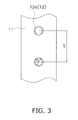
- FIG. 3 is a cross-sectional view of a heat exchanger when divided along line A-A in FIG. 2 .
- the outside diameter of the straight tubes 12a is D
- the distance between the centers of heat transfer tubes 12 that are adjacent in a vertical direction is S.
- the smaller the center-to-center distance S the more improved the fin efficiency, but the greater the airflow resistance.
- the greater the center-to-center distance S the poorer the fin efficiency, but the lesser the airflow resistance.
- the term "fin efficiency” refers to the ratio between the actual quantity of heat radiated from the combined heat transfer surfaces of the fins, and the quantity of heat radiated when the combined heat transfer surfaces of the fins are assumed to be equal in temperature to the refrigerant.
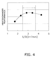
- the heat exchanger performance exhibits a high value in a range of 2.5 ⁇ S/D ⁇ 3.5, and outside of this range the heat exchanger performance decreases.
- FIG. 4 indicates that with the outdoor heat exchanger 4 and the indoor heat exchanger 6 of the refrigerant circuit which uses a mixed refrigerant of HFO-1234yf and HFC-32, the optimal heat exchanger performance is obtained when the relationship between the outside diameter D and the center-to-center distance S is 2.5 ⁇ S/D ⁇ 3.5.
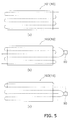
- FIG. 5(a) is a schematic view of the heat exchanger of FIG. 2 when the heat exchanger has one refrigerant passage
- (b) is a schematic view of the heat exchanger of FIG. 2 when the heat exchanger has two refrigerant passages
- (c) is a schematic view of the heat exchanger of FIG. 2 when the refrigerant passage of the heat exchanger branches in two halfway through.
- the heat exchanger 10 has one refrigerant passage and is therefore referred to as a 1-pass heat exchanger 101.
- the refrigerant passage length of the 1-pass heat exchanger 101 is approximately 6H.
- the heat exchanger 10 has two refrigerant passages formed by a flow diverter 90 and is therefore referred to as a 2-pass heat exchanger 102.
- the refrigerant passage length of the 2-pass heat exchanger 102 is equivalent to approximately 3H, which is half that of the 1-pass heat exchanger 101.
- the heat exchanger 10 is referred to as a 1-2 pass heat exchanger 103 because one refrigerant passage branches via the flow diverter 90 into two refrigerant passages partway therealong. Since the 1-2 pass heat exchanger 103 has both a shared refrigerant passage and independent refrigerant passages, the refrigerant passage length cannot be calculated in a simple manner. In view of this, the actual pressure loss of the 1-2 pass heat exchanger 103 is found, a determination is made as to what the length would be of a refrigerant passage having an equivalent pressure loss if there was only one refrigerant passage, and the value thereof is used as the refrigerant passage length.
- FIG. 6 is a graph showing the relationship between refrigerant passage length and pressure loss.
- the refrigerant passage length is 3.6H.
- the 1-pass heat exchanger 101, the 2-pass heat exchanger 102, and the 1-2 pass heat exchanger 103 whose refrigerant passage lengths differ can be created from a single heat exchanger 10 as a reference.
- the refrigerant passage length can be set by varying the quantity of refrigerant passages.
- the reflux rate K is the inverse of the combined resistance of the heat resistance of the air and the heat resistance of the refrigerant.
- the outdoor heat exchanger 4 and the indoor heat exchanger 6 of the refrigerant circuit which uses a mixed refrigerant of HFO-1234yf and HFC-32 cannot be substituted with an outdoor heat exchanger and an indoor heat exchanger corresponding to conventional refrigerant (for example, 410A refrigerant), and in order to achieve the optimal heat exchanger performance, the heat exchanger must be designed after clarifying the relationship between the heat transfer tube outside diameter D and the refrigerant passage length L.
- FIG. 7 shows, the shorter the refrigerant passage length, the smaller the pressure loss, but the lower the refrigerant heat transfer coefficient as well.
- the heat exchanger performance also decreases due to the decrease in the refrigerant heat transfer coefficient, as shown in FIG. 8 .
- FIG 8 indicates that there is a refrigerant passage length suited to the heat transfer tube outside diameter.
- FIG. 9 is a graph in which the refrigerant passage length L is plotted relative to the heat transfer tube outside diameter D.
- the optimal heat exchanger performance is obtained by setting the refrigerant passage length L in a range of 0.28 ⁇ D 1.17 ⁇ L ⁇ 1.10 ⁇ D 1.17 .
- HFO-1234ze (1,3,3,3-tetrafluoro-1-propene
- chemical formula: CF 3 -CH CHF
- these single refrigerants are classified as reference refrigerants.
- the mixed refrigerant may contain 22 mass% of HFC-32.
- the percentage of HFC-32 is preferably 6 mass% or more and 30 mass% or less, more preferably 13 mass% or more and 23 mass% or less, and even more preferably 21 mass% or more and 23 mass% or less.
- the mixed refrigerant may also contain any one of the reference refrigerants listed above and 10 mass% or more of HFC-125 (pentafluoroethane, CF 3 -CHF 2 ), and furthermore, the percentage of HFC-125 is preferably 10 mass% or more and 20 mass% or less.
- the mixed refrigerant may contain any one of the reference refrigerants listed above, and any one of the following: HFC-134 (1,1,2,2-tetrafluoroethane, CHF 2 -CHF 2 ), HFC-134a (1,1,1,2-tetrafluoroethane, CH 2 F-CF 3 ), HFC-143a (1,1,1-trifluoroethane, CH 3 CF 3 ), HFC-152a (1,1-difluoroethane, CHF 2 -CH 3 ), HFC-161 (fluoroethane, CH 3 -CH 2 F), HFC-227ea (1,1,1,2,3,3,3-heptafluoropropane, CF 3 -CHF-CF 3 ), HFC-236ea (1,1,1,2,3,3-hexafluoropropane, CF 3 -CHF-CHF 2 ), HFC-236fa (1,1,1,3,3,3-hexafluoroethane,
- the mixed refrigerant described above is a mixed refrigerant containing any one of the reference refrigerants listed above and an HFC-based refrigerant, but is not limited to these options alone, and may also be a mixed refrigerant containing any one of the reference refrigerants listed above and a hydrocarbon-based refrigerant.
- methane CH 4
- ethane CH 3 -CH 3
- propane CH 3 -CH 2 -CH 3
- butane CH 3 -CH 2 -CH 2 -CH 3
- the mixed refrigerant may also contain any one of the reference refrigerants listed above, and any one of the following: dimethyl ether (CH 3 -O-CH 3 ), bis-trifluoromethylsulfide (CF 3 -S-CF 3 ), carbon dioxide (CO 2 ), and helium (He).
- dimethyl ether CH 3 -O-CH 3
- bis-trifluoromethylsulfide CF 3 -S-CF 3
- CO 2 carbon dioxide
- He helium
- a mixed refrigerant composed of two refrigerants HFO-1234yf and HFC-32 is used as the refrigerant, but a mixed refrigerant composed of any one of the reference refrigerants listed above and any two of the second components listed above may also be used.
- a mixed refrigerant composed of 52 mass% of HFO-1234yf, 23 mass% of HFC-32, and 25 mass% of HFC-125 is preferred.
- the heat exchanger 10 comprises a plurality of heat transfer tubes 12 and a plurality of plate-shaped fins 11.
- the heat transfer tubes 12 form one or a plurality of refrigerant passages for allowing the refrigerant to flow through.
- the plate-shaped fins 11 are disposed substantially parallel to the direction of air flow and the plurality of heat transfer tubes pass through the fins in a substantially vertical manner.
- the relationship between the center-to-center distance S between heat transfer tubes that are adjacent in a vertical direction and the outside diameter D of the heat transfer tubes is 2.5 ⁇ S/D ⁇ 3.5, and the relationship between the refrigerant passage length L and the outside diameter D of the heat transfer tubes is 0.28 ⁇ D 1.17 ⁇ L ⁇ 1.10 ⁇ D 1.17 .
- the effect of refrigerant pressure loss inside the heat transfer tubes is kept to a minimum.
- the specific refrigerant used is either a single refrigerant composed of 2,3,3,3-tetrafluoro-1-propene, a mixed refrigerant containing the single refrigerant, a mixed refrigerant containing 2,3,3,3-tetrafluoro-1-propene and difluoromethane, or a mixed refrigerant containing 2,3,3,3-tetrafluoro-1-propene and pentafluoroethane.
- the present invention is effective in a heat exchanger of a refrigerant circuit which uses a low-pressure refrigerant.
Landscapes
- Engineering & Computer Science (AREA)
- Physics & Mathematics (AREA)
- Thermal Sciences (AREA)
- Mechanical Engineering (AREA)
- General Engineering & Computer Science (AREA)
- Geometry (AREA)
- Heat-Exchange Devices With Radiators And Conduit Assemblies (AREA)
- Cooling Or The Like Of Semiconductors Or Solid State Devices (AREA)
Abstract
Description
- The present invention relates to a heat exchanger, and particularly relates to a heat exchanger suited to a refrigerant circuit which uses a low-pressure refrigerant.
- From a standpoint of protecting the global environment, there is demand that refrigerants used in refrigerant circuits of air-conditioning apparatuses have low global warming potential and do not contribute to damaging the ozone layer. Refrigerants that comply with these requirements are actually being developed (for example, see Patent Document 1).
- The refrigerant disclosed in Patent Document 1 (C3HmFn) has the characteristics of a comparatively high theoretical COP and a low global warming potential. However, since this refrigerant is a so-called low-pressure refrigerant having a comparatively high boiling point, there is a possibility of the input of the compressor increasing and the operating efficiency being reduced due to the effect of pressure loss in the heat exchanger.
- <
Patent Document 1> Japanese Laid-open Patent Application No.4-110388 - An object of the invention is to provide a heat exchanger suited to a refrigerant circuit which uses either a single refrigerant or a mixed refrigerant including the single refrigerant, which is composed of a refrigerant whose molecular formula is expressed as C3HmFn (wherein m = 1 to 5, n = 1 to 5, and m + n = 6) and whose molecular structure has one double bond.
- A heat exchanger according to a first aspect of the present invention is a heat exchanger of a refrigerant circuit in which either a single refrigerant or a mixed refrigerant including the single refrigerant is employed, the single refrigerant comprising an organic compound whose molecular formula is expressed as C3HmFn (wherein m = 1 to 5, n = 1 to 5, and m + n = 6) and whose molecular structure has one double bond, the heat exchanger comprising a plurality of heat transfer tubes and a plurality of plate-shaped fins. The heat transfer tubes form one or a plurality of refrigerant passages for allowing the refrigerant to flow therethrough. The plate-shaped fins are aligned so as to be stacked at a predetermined spacing, and the plurality of heat transfer tubes pass through the fins in a substantially vertical manner. The relationship between the center-to-center distance S between heat transfer tubes that are adjacent in the vertical direction and the outside diameter D of the heat transfer tubes is 2.5 < S/D < 3.5, and the relationship between the length L of the refrigerant passages and the outside diameter D of the heat transfer tubes is 0.28 × D1.17 < L < 1.10 × D1.17.
- Since the refrigerant is a low-pressure refrigerant, the refrigerant is susceptible to the effect of pressure loss inside the heat transfer tubes, but in this heat exchanger, the effect of pressure loss on the refrigerant inside the heat transfer tubes can be kept to a minimum by applying the relationship between the refrigerant passage length L, the outside diameter D of the heat transfer tubes and the center-to-center distance S between heat transfer tubes to the above relational expressions.
- The heat exchanger according to a second aspect of the present invention is the heat exchanger according to the first aspect of the present invention, wherein the refrigerant is either a single refrigerant comprising 2,3,3,3-tetrafluoro-1-propene or a mixed refrigerant containing the single refrigerant.
- Since either the single refrigerant composed of 2,3,3,3-tetrafluoro-1-propene or the mixed refrigerant containing the single refrigerant is a low-pressure refrigerant, the refrigerant is susceptible to the effect of pressure loss inside the heat transfer tubes, but in this heat exchanger, the effect of pressure loss on the refrigerant inside the heat transfer tubes can be kept to a minimum by applying the relationship between the refrigerant passage length L, the outside diameter D of the heat transfer tubes and the center-to-center distance S between heat transfer tubes to the above relational expressions.
- The heat exchanger according to a third aspect of the present invention is the heat exchanger according to the first aspect of the present invention, wherein the refrigerant is a mixed refrigerant comprising 2,3,3,3-tetrafluoro-1-propene and difluoromethane.
- Since the mixed refrigerant containing 2,3,3,3-tetrafluoro-1-propene and difluoromethane is a low-pressure refrigerant, the refrigerant is susceptible to the effect of pressure loss inside the heat transfer tubes, but in this heat exchanger, the effect of pressure loss on the refrigerant inside the heat transfer tubes can be kept to a minimum by applying the relationship between the refrigerant passage length L, the outside diameter D of the heat transfer tubes and the center-to-center distance S between heat transfer tubes to the above relational expressions.
- The heat exchanger according to a fourth aspect of the present invention is the heat exchanger according to the first aspect of the present invention, wherein the refrigerant is a mixed refrigerant comprising 2,3,3,3-tetrafluoro-1-propene and pentafluoroethane.
- Since the mixed refrigerant containing 2,3,3,3-tetrafluoro-1-propene and pentafluoroethane is a low-pressure refrigerant, the refrigerant is susceptible to the effect of pressure loss inside the heat transfer tubes, but in this heat exchanger, the effect of pressure loss on the refrigerant inside the heat transfer tubes can be kept to a minimum by applying the relationship between the refrigerant passage length L, the outside diameter D of the heat transfer tubes and the center-to-center distance S between heat transfer tubes to the above relational expressions.
- In the heat exchanger according to any of the first, second, third, and fourth aspects of the present invention, the effect of pressure loss on the refrigerant inside the heat transfer tubes can be kept to a minimum by applying the relationship between the refrigerant passage length L, the outside diameter D of the heat transfer tubes and the center-to-center distance S between heat transfer tubes to the above relational expressions.
-
-
FIG. 1 is a refrigerant circuit of an air-conditioning apparatus. -
FIG. 2 is a front view of a heat exchanger according to an embodiment of the present invention. -
FIG. 3 is a cross-sectional view of the heat exchanger when divided along line A-A inFIG. 2 . -
FIG. 4 is a graph showing the relationship between S/D and the heat exchanger performance when the air blower power is constant and D = 7 mm. -
FIG 5(a) is a schematic view of the heat exchanger ofFIG. 2 when the heat exchanger has one refrigerant passage; (b) is a schematic view of the heat exchanger ofFIG. 2 when the heat exchanger has two refrigerant passages; and (c) is a schematic view of the heat exchanger ofFIG. 2 when the refrigerant passage of the heat exchanger branches in two halfway through. -
FIG. 6 is a graph showing the relationship between refrigerant passage length and pressure loss. -
FIG. 7 is a graph showing the relationship of the refrigerant passage length to the refrigerant heat transfer coefficient as well as to the pressure loss when D = 7 mm. -
FIG. 8 is a graph showing the refrigerant passage length and the heat exchanger performance when D = 7 mm. -
FIG. 9 is a graph in which the refrigerant passage length L is plotted relative to the heat transfer tube outside diameter D. -
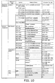
FIG. 10 is a composition table of refrigerants used in the refrigerant circuit containing the heat exchanger according to the present embodiment. -
- 4
- Outdoor heat exchanger
- 6
- Indoor heat exchanger
- 10
- Heat exchanger
- 11
- Plate-shaped fin
- 12
- Heat-transfer tube
-
FIG. 1 is a refrigerant circuit of an air-conditioning apparatus. The air-conditioning apparatus 1 has a refrigeration circuit in which acompressor 2, a four-way switching valve 3, anoutdoor heat exchanger 4, anexpansion valve 5, and anindoor heat exchanger 6 are connected by a refrigerant pipe. InFIG 1 , the solid-line and dashed-line arrows indicate directions of refrigerant flow, and in the air-conditioning apparatus 1, it is possible to switch between an air-warming operation and an air-cooling operation by switching the direction of refrigerant flow via the four-way switching valve 3. During the air-cooling operation, theoutdoor heat exchanger 4 serves as a condenser and theindoor heat exchanger 6 serves as an evaporator. During the air-warming operation, theoutdoor heat exchanger 4 serves as an evaporator and theindoor heat exchanger 6 serves as a condenser. - The refrigerant circuit is filled with a mixed refrigerant composed of the two organic compounds HFO-1234yf (2, 3, 3, 3-tetrafluoro-1-propene) and HFC-32 (difluoromethane). The refrigerant used in the present embodiment is a mixed refrigerant composed of 78.2 mass% of HFO-1234yf and 21.8 mass% of HFC-32. The chemical formula of HFO-1234yf is expressed as CF3CFCH2, and the chemical formula of HFC-32 is expressed as CH2F2.
-
FIG 2 is a front view of a heat exchanger according to an embodiment of the present invention. InFIG. 2 , theheat exchanger 10 is a cross-fin type heat exchanger, and is a basic model of theoutdoor heat exchanger 4 and theindoor heat exchanger 6 shown inFIG. 1 . Theheat exchanger 10 comprisesfins 11 andheat transfer tubes 12. Thefins 11 are thin flat plates made of aluminum, and a plurality of through-holes are formed in eachfin 11. Theheat transfer tubes 12 are composed ofstraight tubes 12a inserted through the through-holes of thefins 11, andfirst U-shaped tubes 12b andsecond U-shaped tubes 12c connecting the ends of adjacentstraight tubes 12a to each other. Thestraight tubes 12a and thefirst U-shaped tubes 12b are formed integrally, and thesecond U-shaped tubes 12c are connected to the ends of thestraight tubes 12a by welding or another method after thestraight tubes 12a have been inserted through the through-holes of thefins 11. -
FIG. 3 is a cross-sectional view of a heat exchanger when divided along line A-A inFIG. 2 . InFIG. 3 , the outside diameter of thestraight tubes 12a is D, and the distance between the centers ofheat transfer tubes 12 that are adjacent in a vertical direction is S. Generally, the smaller the center-to-center distance S, the more improved the fin efficiency, but the greater the airflow resistance. Conversely, the greater the center-to-center distance S, the poorer the fin efficiency, but the lesser the airflow resistance. The term "fin efficiency" refers to the ratio between the actual quantity of heat radiated from the combined heat transfer surfaces of the fins, and the quantity of heat radiated when the combined heat transfer surfaces of the fins are assumed to be equal in temperature to the refrigerant. - When the center-to-center distance S is constant, the greater the tube outside diameter D, the more improved the fin efficiency, but the greater the airflow resistance. Conversely, the smaller the tube outside diameter D, the poorer the fin efficiency, but the lesser the airflow resistance. In other words, between the tube outside diameter D and the center-to-center distance S, there exists an optimal condition for improving the heat exchanger performance.
-
FIG. 4 is a graph showing the relationship between S/D and the heat exchanger performance when the air blower power is constant and D = 7 mm. InFIG. 4 , the heat exchanger performance exhibits a high value in a range of 2.5 < S/D < 3.5, and outside of this range the heat exchanger performance decreases. In other words,FIG. 4 indicates that with theoutdoor heat exchanger 4 and theindoor heat exchanger 6 of the refrigerant circuit which uses a mixed refrigerant of HFO-1234yf and HFC-32, the optimal heat exchanger performance is obtained when the relationship between the outside diameter D and the center-to-center distance S is 2.5 < S/D < 3.5. -
FIG. 5(a) is a schematic view of the heat exchanger ofFIG. 2 when the heat exchanger has one refrigerant passage, (b) is a schematic view of the heat exchanger ofFIG. 2 when the heat exchanger has two refrigerant passages, and (c) is a schematic view of the heat exchanger ofFIG. 2 when the refrigerant passage of the heat exchanger branches in two halfway through. - In
FIG. 5(a) , theheat exchanger 10 has one refrigerant passage and is therefore referred to as a 1-pass heat exchanger 101. In cases in which theheat exchanger 10 has sixheat transfer tubes 12 and the length of oneheat transfer tube 12 is denoted as H, the refrigerant passage length of the 1-pass heat exchanger 101 is approximately 6H. - In
FIG. 5(b) , theheat exchanger 10 has two refrigerant passages formed by aflow diverter 90 and is therefore referred to as a 2-pass heat exchanger 102. The refrigerant passage length of the 2-pass heat exchanger 102 is equivalent to approximately 3H, which is half that of the 1-pass heat exchanger 101. - In
FIG. 5(c) , theheat exchanger 10 is referred to as a 1-2pass heat exchanger 103 because one refrigerant passage branches via theflow diverter 90 into two refrigerant passages partway therealong. Since the 1-2pass heat exchanger 103 has both a shared refrigerant passage and independent refrigerant passages, the refrigerant passage length cannot be calculated in a simple manner. In view of this, the actual pressure loss of the 1-2pass heat exchanger 103 is found, a determination is made as to what the length would be of a refrigerant passage having an equivalent pressure loss if there was only one refrigerant passage, and the value thereof is used as the refrigerant passage length. -
FIG. 6 is a graph showing the relationship between refrigerant passage length and pressure loss. For example, when the refrigerant pressure loss in the 1-2pass heat exchanger 103 ofFIG. 5(c) is p, according to the graph, the refrigerant passage length is 3.6H. Thus, the 1-pass heat exchanger 101, the 2-pass heat exchanger 102, and the 1-2pass heat exchanger 103 whose refrigerant passage lengths differ can be created from asingle heat exchanger 10 as a reference. In other words, the refrigerant passage length can be set by varying the quantity of refrigerant passages. - Next, the relationship between refrigerant passage length and heat exchanger performance will be described. To be clear the heat exchanger performance Q is expressed by the equation Q = KA × dT, using the heat reflux rate K, the heat transfer surface area A, and the temperature difference dT between the air and the refrigerant. The reflux rate K is the inverse of the combined resistance of the heat resistance of the air and the heat resistance of the refrigerant. The combined
resistance 1/K is expressed by theequation 1/K = 1/ha + R/hr, using the air heat transfer coefficient ha, the refrigerant heat transfer coefficient hr, and the inside-outside heat transfer surface area ratio R. - When the number of refrigerant passages is reduced and the refrigerant passage length is increased, the quantity of refrigerant flowing through one refrigerant passage increases and the refrigerant heat transfer coefficient hr improves, but since the evaporation temperature in the heat exchanger inlet increases due to the increase in pressure loss, the temperature difference dT between the air and the refrigerant decreases, and the heat exchanger performance Q decreases.
- When the number of refrigerant passages is increased and the refrigerant passage length is reduced, the pressure loss decreases, the evaporation temperature in the heat exchanger inlet decreases, and the temperature difference dT between the air and the refrigerant increases, but since the quantity of refrigerant flowing through one refrigerant passage decreases, the refrigerant heat transfer coefficient hr decreases and the heat exchanger performance Q decreases.
- In other words, the
outdoor heat exchanger 4 and theindoor heat exchanger 6 of the refrigerant circuit which uses a mixed refrigerant of HFO-1234yf and HFC-32 cannot be substituted with an outdoor heat exchanger and an indoor heat exchanger corresponding to conventional refrigerant (for example, 410A refrigerant), and in order to achieve the optimal heat exchanger performance, the heat exchanger must be designed after clarifying the relationship between the heat transfer tube outside diameter D and the refrigerant passage length L. -
FIG. 7 is a graph showing the relationship of the refrigerant passage length to the refrigerant heat transfer coefficient as well as to the pressure loss when D = 7 mm, andFIG. 8 is a graph showing the refrigerant passage length and the heat exchanger performance when D = 7 mm. AsFIG. 7 shows, the shorter the refrigerant passage length, the smaller the pressure loss, but the lower the refrigerant heat transfer coefficient as well. As a result, the heat exchanger performance also decreases due to the decrease in the refrigerant heat transfer coefficient, as shown inFIG. 8 . When the refrigerant passage length is increased, the heat exchanger performance peaks at first, but thereafter falls. In other words,FIG 8 indicates that there is a refrigerant passage length suited to the heat transfer tube outside diameter. -
FIG. 9 is a graph in which the refrigerant passage length L is plotted relative to the heat transfer tube outside diameter D. InFIG. 9 , the square black points indicate the optimal refrigerant passage length corresponding to the heat transfer tube outside diameter, where the lower limit of the refrigerant passage length corresponding to the heat transfer tube outside diameter lies on the line y = 0.28x1.17, and the upper limit lies on the line y = 1.10x1.17. In other words, it is indicated that with theoutdoor heat exchanger 4 and theindoor heat exchanger 6 of the refrigerant circuit which uses a mixed refrigerant of HFO-1234yf and HFC-32, the optimal heat exchanger performance is obtained by setting the refrigerant passage length L in a range of 0.28 × D1.17 < L < 1.10 × D1.17. - In the embodiment described above, a mixed refrigerant composed of two organic compounds HFO-1234yf and HFC-32 is used as the refrigerant, but the refrigerant is not limited to this option alone. For example,
FIG. 10 is a composition table of refrigerants used in the refrigerant circuit containing the heat exchanger according to the present embodiment, and a single refrigerant composed of an organic compound whose molecular formula is expressed as C3HmFn (wherein m = 1 to 5, n = 1 to 5, and m + n = 6) and whose molecular structure has one double bond, such as HFO-1234yf, may be used. - Specifically, possible examples as shown in the upper row of
FIG. 10 include HFO-1225ye (1,2,3,3,3-pentafluoro-1-propene, chemical formula: CF3-CF=CHF), HFO-1234ze (1,3,3,3-tetrafluoro-1-propene, chemical formula: CF3-CH=CHF), HFO-1234ye (1,2,3,3-tetrafluoro-1-propene, chemical formula: CHF2-CF=CHF), HFO-1243zf (3,3,3-trifluoro-1-propene, chemical formula: CF3-CH=CH2, or 1,2,2-trifluoro-1-propene, chemical formula: CH3-CF=CF2), 2-fluoro-1-propene (chemical formula: CH3-CF=CH2), and the like. For the sake of convenience in the description, these single refrigerants are classified as reference refrigerants. - Another option is to use a mixed refrigerant composed of any one of the reference refrigerants listed above and any one of the second components shown in
FIG. 10 . For example, the mixed refrigerant may contain 22 mass% of HFC-32. Furthermore, the percentage of HFC-32 is preferably 6 mass% or more and 30 mass% or less, more preferably 13 mass% or more and 23 mass% or less, and even more preferably 21 mass% or more and 23 mass% or less. - The mixed refrigerant may also contain any one of the reference refrigerants listed above and 10 mass% or more of HFC-125 (pentafluoroethane, CF3-CHF2), and furthermore, the percentage of HFC-125 is preferably 10 mass% or more and 20 mass% or less.
- The mixed refrigerant may contain any one of the reference refrigerants listed above, and any one of the following: HFC-134 (1,1,2,2-tetrafluoroethane, CHF2-CHF2), HFC-134a (1,1,1,2-tetrafluoroethane, CH2F-CF3), HFC-143a (1,1,1-trifluoroethane, CH3CF3), HFC-152a (1,1-difluoroethane, CHF2-CH3), HFC-161 (fluoroethane, CH3-CH2F), HFC-227ea (1,1,1,2,3,3,3-heptafluoropropane, CF3-CHF-CF3), HFC-236ea (1,1,1,2,3,3-hexafluoropropane, CF3-CHF-CHF2), HFC-236fa (1,1,1,3,3,3-hexafluoroethane, CF3-CH2-CF3), and HFC-365mfc (1,1,1,3,3-pentafluorobutane, CF3-CH2CF2-CH3).
- The mixed refrigerant described above is a mixed refrigerant containing any one of the reference refrigerants listed above and an HFC-based refrigerant, but is not limited to these options alone, and may also be a mixed refrigerant containing any one of the reference refrigerants listed above and a hydrocarbon-based refrigerant.
- Specifically, the mixed refrigerant may contain any one of the reference refrigerants listed above, and any one of the following: methane (CH4), ethane (CH3-CH3), propane (CH3-CH2-CH3), propene (CH3-CH=CH2), butane (CH3-CH2-CH2-CH3), isobutane (CH3-CH(CH3)-CH3), pentane, (CH3-CH2-CH2-CH2-CH3), 2-methylbutane (CH3-CH(CH3)-CH2-CH3), and cyclopentane (cyclo-C5H10).
- The mixed refrigerant may also contain any one of the reference refrigerants listed above, and any one of the following: dimethyl ether (CH3-O-CH3), bis-trifluoromethylsulfide (CF3-S-CF3), carbon dioxide (CO2), and helium (He).
- In the embodiment described above, a mixed refrigerant composed of two refrigerants HFO-1234yf and HFC-32 is used as the refrigerant, but a mixed refrigerant composed of any one of the reference refrigerants listed above and any two of the second components listed above may also be used. For example, a mixed refrigerant composed of 52 mass% of HFO-1234yf, 23 mass% of HFC-32, and 25 mass% of HFC-125 is preferred.
- The
heat exchanger 10 is used as a heat exchanger of a refrigerant circuit which uses either a single refrigerant or a mixed refrigerant including the single refrigerant, which is composed of an organic compound whose molecular formula is expressed as C3HmFn (wherein m = 1 to 5, n = 1 to 5, and m + n = 6) and whose molecular structure has one double bond. Theheat exchanger 10 comprises a plurality ofheat transfer tubes 12 and a plurality of plate-shapedfins 11. Theheat transfer tubes 12 form one or a plurality of refrigerant passages for allowing the refrigerant to flow through. The plate-shapedfins 11 are disposed substantially parallel to the direction of air flow and the plurality of heat transfer tubes pass through the fins in a substantially vertical manner. The relationship between the center-to-center distance S between heat transfer tubes that are adjacent in a vertical direction and the outside diameter D of the heat transfer tubes is 2.5 < S/D < 3.5, and the relationship between the refrigerant passage length L and the outside diameter D of the heat transfer tubes is 0.28 × D1.17 < L < 1.10 × D1.17. As a result, the effect of refrigerant pressure loss inside the heat transfer tubes is kept to a minimum. The specific refrigerant used is either a single refrigerant composed of 2,3,3,3-tetrafluoro-1-propene, a mixed refrigerant containing the single refrigerant, a mixed refrigerant containing 2,3,3,3-tetrafluoro-1-propene and difluoromethane, or a mixed refrigerant containing 2,3,3,3-tetrafluoro-1-propene and pentafluoroethane. - As described above, the present invention is effective in a heat exchanger of a refrigerant circuit which uses a low-pressure refrigerant.
Claims (4)
- A heat exchanger (4, 6, 10) of a refrigerant circuit in which either a single refrigerant or a mixed refrigerant including the single refrigerant is employed, the single refrigerant comprising an organic compound whose molecular formula is expressed as C3HmFn (wherein m = 1 to 5, n = 1 to 5, and m + n = 6) and whose molecular structure has one double bond, the heat exchanger comprising:a plurality of heat transfer tubes (12) which form one or a plurality of refrigerant passages for allowing the refrigerant to flow therethrough; anda plurality of plate-shaped fins (11) aligned to be stacked at a predetermined spacing through which the heat transfer tubes (12) pass through in a substantially vertical manner; whereinthe relationship between a center-to-center distance S between the heat transfer tubes (12) that are adjacent in the vertical direction and an outside diameter D of the heat transfer tubes (12) is

andthe relationship between the length L of the refrigerant passages and the outside diameter D of the heat transfer tubes (12) is
- The heat exchanger (4, 6, 10) according to claim 1, wherein
the refrigerant is either a single refrigerant comprising 2,3,3,3-tetrafluoro-1-propene or a mixed refrigerant containing the single refrigerant. - The heat exchanger (4, 6, 10) according to claim 1, wherein
the refrigerant is a mixed refrigerant comprising 2,3,3,3-tetrafluoro-1-propene and difluoromethane. - The heat exchanger (4, 6, 10) according to claim 1, wherein
the refrigerant is a mixed refrigerant comprising 2,3,3,3-tetrafluoro-1-propene and pentafluoroethane.
Applications Claiming Priority (2)
| Application Number | Priority Date | Filing Date | Title |
|---|---|---|---|
| JP2008070356A JP2009222360A (en) | 2008-03-18 | 2008-03-18 | Heat exchanger |
| PCT/JP2009/054999 WO2009116478A1 (en) | 2008-03-18 | 2009-03-16 | Heat exchanger |
Publications (2)
| Publication Number | Publication Date |
|---|---|
| EP2267392A1 true EP2267392A1 (en) | 2010-12-29 |
| EP2267392A4 EP2267392A4 (en) | 2014-03-26 |
Family
ID=41090881
Family Applications (1)
| Application Number | Title | Priority Date | Filing Date |
|---|---|---|---|
| EP09722156.8A Withdrawn EP2267392A4 (en) | 2008-03-18 | 2009-03-16 | Heat Exchanger |
Country Status (6)
| Country | Link |
|---|---|
| US (1) | US20110011126A1 (en) |
| EP (1) | EP2267392A4 (en) |
| JP (1) | JP2009222360A (en) |
| CN (1) | CN101978236B (en) |
| BR (1) | BRPI0908721A2 (en) |
| WO (1) | WO2009116478A1 (en) |
Families Citing this family (6)
| Publication number | Priority date | Publication date | Assignee | Title |
|---|---|---|---|---|
| JP5176624B2 (en) * | 2008-03-18 | 2013-04-03 | ダイキン工業株式会社 | Refrigeration equipment |
| DK2528983T3 (en) | 2010-01-27 | 2021-01-11 | Daikin Ind Ltd | USE OF REFRIGERATOR COMPOSITION INCLUDING DIFLUOROMETHANE (HFC-32) AND 2,3,3,3-TETRAFLUOROPROPHENE (HFO-1234YF) |
| JP2013134024A (en) * | 2011-12-27 | 2013-07-08 | Panasonic Corp | Refrigeration cycle device |
| WO2013160951A1 (en) * | 2012-04-26 | 2013-10-31 | 三菱電機株式会社 | Heat exchanger, method for manufacturing heat exchanger, and air conditioner |
| ES2905258T3 (en) * | 2012-09-04 | 2022-04-07 | Daikin Ind Ltd | Method for filling a mixed refrigerant containing 2,3,3,3-tetrafluoropropene |
| WO2016009565A1 (en) * | 2014-07-18 | 2016-01-21 | 三菱電機株式会社 | Refrigeration cycle device |
Family Cites Families (23)
| Publication number | Priority date | Publication date | Assignee | Title |
|---|---|---|---|---|
| JP2604722B2 (en) * | 1986-06-23 | 1997-04-30 | 松下冷機株式会社 | Flying ube type heat exchanger |
| JPH04110388A (en) * | 1990-08-31 | 1992-04-10 | Daikin Ind Ltd | heat transfer fluid |
| JPH08247576A (en) * | 1995-03-14 | 1996-09-27 | Toshiba Corp | Air conditioner |
| TW340180B (en) * | 1995-09-14 | 1998-09-11 | Sanyo Electric Co | Heat exchanger having corrugated fins and air conditioner having the same |
| JP2001091183A (en) * | 1999-07-21 | 2001-04-06 | Matsushita Refrig Co Ltd | Fin tube type heat exchanger |
| JP2001304783A (en) * | 2000-04-14 | 2001-10-31 | Daikin Ind Ltd | Outdoor heat exchanger, indoor heat exchanger, and air conditioner |
| JP2002147981A (en) * | 2000-11-07 | 2002-05-22 | Kobe Steel Ltd | Heat exchanger tube and finned tube heat exchanger |
| US6460372B1 (en) * | 2001-05-04 | 2002-10-08 | Carrier Corporation | Evaporator for medium temperature refrigerated merchandiser |
| US6857288B2 (en) * | 2002-02-28 | 2005-02-22 | Lg Electronics Inc. | Heat exchanger for refrigerator |
| JP2003343942A (en) * | 2002-05-23 | 2003-12-03 | Denso Corp | Evaporator |
| US9005467B2 (en) * | 2003-10-27 | 2015-04-14 | Honeywell International Inc. | Methods of replacing heat transfer fluids |
| US8444874B2 (en) * | 2002-10-25 | 2013-05-21 | Honeywell International Inc. | Heat transfer methods using heat transfer compositions containing trans-1,3,3,3-tetrafluoropropene |
| US7279451B2 (en) * | 2002-10-25 | 2007-10-09 | Honeywell International Inc. | Compositions containing fluorine substituted olefins |
| US9796848B2 (en) * | 2002-10-25 | 2017-10-24 | Honeywell International Inc. | Foaming agents and compositions containing fluorine substituted olefins and methods of foaming |
| US20040089839A1 (en) * | 2002-10-25 | 2004-05-13 | Honeywell International, Inc. | Fluorinated alkene refrigerant compositions |
| US20080121837A1 (en) * | 2003-10-27 | 2008-05-29 | Honeywell International, Inc. | Compositions containing fluorine substituted olefins |
| ATE556124T1 (en) * | 2002-10-25 | 2012-05-15 | Honeywell Int Inc | COMPOSITIONS CONTAINING FLUOROUS SUBSTITUTED OLEFINS |
| CA2534773C (en) * | 2003-08-06 | 2011-11-01 | Shell Internationale Research Maatschappij B.V. | Support for a tube bundle |
| JP2006317010A (en) * | 2004-08-09 | 2006-11-24 | Kiyoshi Yanagimachi | Heat exchanger block |
| US8420706B2 (en) * | 2005-06-24 | 2013-04-16 | Honeywell International Inc. | Foaming agents, foamable compositions, foams and articles containing halogen substituted olefins, and methods of making same |
| TWI482748B (en) * | 2005-06-24 | 2015-05-01 | Honeywell Int Inc | Compositions containing fluorine substituted olefins |
| CA2513989C (en) * | 2005-07-27 | 2007-02-06 | Aker Kvaerner Canada Inc. | Improved heat exchanger |
| US7740057B2 (en) * | 2007-02-09 | 2010-06-22 | Xi'an Jiaotong University | Single shell-pass or multiple shell-pass shell-and-tube heat exchanger with helical baffles |
-
2008
- 2008-03-18 JP JP2008070356A patent/JP2009222360A/en active Pending
-
2009
- 2009-03-16 CN CN2009801097035A patent/CN101978236B/en active Active
- 2009-03-16 US US12/922,259 patent/US20110011126A1/en not_active Abandoned
- 2009-03-16 EP EP09722156.8A patent/EP2267392A4/en not_active Withdrawn
- 2009-03-16 WO PCT/JP2009/054999 patent/WO2009116478A1/en not_active Ceased
- 2009-03-16 BR BRPI0908721-4A patent/BRPI0908721A2/en not_active Application Discontinuation
Also Published As
| Publication number | Publication date |
|---|---|
| JP2009222360A (en) | 2009-10-01 |
| US20110011126A1 (en) | 2011-01-20 |
| BRPI0908721A2 (en) | 2020-08-11 |
| CN101978236A (en) | 2011-02-16 |
| EP2267392A4 (en) | 2014-03-26 |
| WO2009116478A1 (en) | 2009-09-24 |
| CN101978236B (en) | 2012-09-05 |
Similar Documents
| Publication | Publication Date | Title |
|---|---|---|
| EP2249104A1 (en) | Refrigerating apparatus | |
| EP2427527B1 (en) | Heat transfer compositions and methods | |
| JP5423089B2 (en) | Refrigeration equipment | |
| US11624534B2 (en) | Method for exchanging heat in vapor compression heat transfer systems and vapor compression heat transfer systems comprising intermediate heat exchangers with dual-row evaporators or condensers | |
| US9011711B2 (en) | Heat transfer fluid replacing R-410A | |
| US9683157B2 (en) | Heat transfer method | |
| US10035938B2 (en) | Heat transfer fluid replacing R-134a | |
| CN102884152B (en) | Heat transfer fluids and their use in counterflow heat exchangers | |
| EP3730576A1 (en) | Refrigeration cycle device | |
| JP6065429B2 (en) | Air conditioner | |
| EP2246649A1 (en) | Refrigerating apparatus | |
| EP3470489B1 (en) | Working fluid for heat cycle, a process for its preparation, composition for heat cycle system, and heat cycle system | |
| US20110011126A1 (en) | Heat exchanger | |
| EP2591296A2 (en) | Cascade refrigeration system with fluoroolefin refrigerant | |
| CN110730812B (en) | Refrigerant-containing composition, use thereof, freezing method using the composition, and freezer comprising the composition | |
| JP2011094841A (en) | Refrigerating device | |
| JP5239427B2 (en) | Method for updating air conditioner | |
| JP2009222356A (en) | Refrigeration device and refrigerant filling method | |
| CN106543963B (en) | Environment-friendly refrigeration composition | |
| JP7354271B2 (en) | Refrigeration cycle equipment | |
| Li et al. | Optimization of a Residential Air Source Heat Pump using Refrigerants with GWP< 150 for Improved Performance and Reduced Emission | |
| AU2017201944A1 (en) | Heat transfer compositions and methods |
Legal Events
| Date | Code | Title | Description |
|---|---|---|---|
| PUAI | Public reference made under article 153(3) epc to a published international application that has entered the european phase |
Free format text: ORIGINAL CODE: 0009012 |
|
| 17P | Request for examination filed |
Effective date: 20101005 |
|
| AK | Designated contracting states |
Kind code of ref document: A1 Designated state(s): AT BE BG CH CY CZ DE DK EE ES FI FR GB GR HR HU IE IS IT LI LT LU LV MC MK MT NL NO PL PT RO SE SI SK TR |
|
| AX | Request for extension of the european patent |
Extension state: AL BA RS |
|
| DAX | Request for extension of the european patent (deleted) | ||
| A4 | Supplementary search report drawn up and despatched |
Effective date: 20140224 |
|
| RIC1 | Information provided on ipc code assigned before grant |
Ipc: F28F 1/32 20060101AFI20140218BHEP Ipc: F25B 1/00 20060101ALI20140218BHEP |
|
| STAA | Information on the status of an ep patent application or granted ep patent |
Free format text: STATUS: EXAMINATION IS IN PROGRESS |
|
| 17Q | First examination report despatched |
Effective date: 20161123 |
|
| STAA | Information on the status of an ep patent application or granted ep patent |
Free format text: STATUS: THE APPLICATION IS DEEMED TO BE WITHDRAWN |
|
| 18D | Application deemed to be withdrawn |
Effective date: 20170404 |