EP2267356A1 - Light fitting arrangement - Google Patents
Light fitting arrangement Download PDFInfo
- Publication number
- EP2267356A1 EP2267356A1 EP10166225A EP10166225A EP2267356A1 EP 2267356 A1 EP2267356 A1 EP 2267356A1 EP 10166225 A EP10166225 A EP 10166225A EP 10166225 A EP10166225 A EP 10166225A EP 2267356 A1 EP2267356 A1 EP 2267356A1
- Authority
- EP
- European Patent Office
- Prior art keywords
- reflector
- housing
- housings
- light fitting
- reflector housing
- Prior art date
- Legal status (The legal status is an assumption and is not a legal conclusion. Google has not performed a legal analysis and makes no representation as to the accuracy of the status listed.)
- Granted
Links
- 230000000295 complement effect Effects 0.000 claims abstract description 14
- 238000000034 method Methods 0.000 claims description 18
- 238000004519 manufacturing process Methods 0.000 claims description 12
- 229910052751 metal Inorganic materials 0.000 claims description 7
- 239000002184 metal Substances 0.000 claims description 7
- 239000000463 material Substances 0.000 description 7
- 239000004411 aluminium Substances 0.000 description 4
- 229910052782 aluminium Inorganic materials 0.000 description 4
- XAGFODPZIPBFFR-UHFFFAOYSA-N aluminium Chemical compound [Al] XAGFODPZIPBFFR-UHFFFAOYSA-N 0.000 description 4
- 238000005286 illumination Methods 0.000 description 4
- 125000006850 spacer group Chemical group 0.000 description 3
- 230000000694 effects Effects 0.000 description 2
- 238000009434 installation Methods 0.000 description 2
- 229920003023 plastic Polymers 0.000 description 2
- 239000004033 plastic Substances 0.000 description 2
- 229910000831 Steel Inorganic materials 0.000 description 1
- 230000015572 biosynthetic process Effects 0.000 description 1
- 238000007689 inspection Methods 0.000 description 1
- 230000005855 radiation Effects 0.000 description 1
- 238000009877 rendering Methods 0.000 description 1
- 239000010959 steel Substances 0.000 description 1
- 238000001429 visible spectrum Methods 0.000 description 1
Images



Classifications
-
- F—MECHANICAL ENGINEERING; LIGHTING; HEATING; WEAPONS; BLASTING
- F21—LIGHTING
- F21S—NON-PORTABLE LIGHTING DEVICES; SYSTEMS THEREOF; VEHICLE LIGHTING DEVICES SPECIALLY ADAPTED FOR VEHICLE EXTERIORS
- F21S2/00—Systems of lighting devices, not provided for in main groups F21S4/00 - F21S10/00 or F21S19/00, e.g. of modular construction
-
- F—MECHANICAL ENGINEERING; LIGHTING; HEATING; WEAPONS; BLASTING
- F21—LIGHTING
- F21S—NON-PORTABLE LIGHTING DEVICES; SYSTEMS THEREOF; VEHICLE LIGHTING DEVICES SPECIALLY ADAPTED FOR VEHICLE EXTERIORS
- F21S2/00—Systems of lighting devices, not provided for in main groups F21S4/00 - F21S10/00 or F21S19/00, e.g. of modular construction
- F21S2/005—Systems of lighting devices, not provided for in main groups F21S4/00 - F21S10/00 or F21S19/00, e.g. of modular construction of modular construction
-
- F—MECHANICAL ENGINEERING; LIGHTING; HEATING; WEAPONS; BLASTING
- F21—LIGHTING
- F21V—FUNCTIONAL FEATURES OR DETAILS OF LIGHTING DEVICES OR SYSTEMS THEREOF; STRUCTURAL COMBINATIONS OF LIGHTING DEVICES WITH OTHER ARTICLES, NOT OTHERWISE PROVIDED FOR
- F21V17/00—Fastening of component parts of lighting devices, e.g. shades, globes, refractors, reflectors, filters, screens, grids or protective cages
- F21V17/02—Fastening of component parts of lighting devices, e.g. shades, globes, refractors, reflectors, filters, screens, grids or protective cages with provision for adjustment
-
- F—MECHANICAL ENGINEERING; LIGHTING; HEATING; WEAPONS; BLASTING
- F21—LIGHTING
- F21V—FUNCTIONAL FEATURES OR DETAILS OF LIGHTING DEVICES OR SYSTEMS THEREOF; STRUCTURAL COMBINATIONS OF LIGHTING DEVICES WITH OTHER ARTICLES, NOT OTHERWISE PROVIDED FOR
- F21V17/00—Fastening of component parts of lighting devices, e.g. shades, globes, refractors, reflectors, filters, screens, grids or protective cages
- F21V17/10—Fastening of component parts of lighting devices, e.g. shades, globes, refractors, reflectors, filters, screens, grids or protective cages characterised by specific fastening means or way of fastening
- F21V17/104—Fastening of component parts of lighting devices, e.g. shades, globes, refractors, reflectors, filters, screens, grids or protective cages characterised by specific fastening means or way of fastening using feather joints, e.g. tongues and grooves, with or without friction
-
- F—MECHANICAL ENGINEERING; LIGHTING; HEATING; WEAPONS; BLASTING
- F21—LIGHTING
- F21V—FUNCTIONAL FEATURES OR DETAILS OF LIGHTING DEVICES OR SYSTEMS THEREOF; STRUCTURAL COMBINATIONS OF LIGHTING DEVICES WITH OTHER ARTICLES, NOT OTHERWISE PROVIDED FOR
- F21V7/00—Reflectors for light sources
- F21V7/005—Reflectors for light sources with an elongated shape to cooperate with linear light sources
-
- F—MECHANICAL ENGINEERING; LIGHTING; HEATING; WEAPONS; BLASTING
- F21—LIGHTING
- F21V—FUNCTIONAL FEATURES OR DETAILS OF LIGHTING DEVICES OR SYSTEMS THEREOF; STRUCTURAL COMBINATIONS OF LIGHTING DEVICES WITH OTHER ARTICLES, NOT OTHERWISE PROVIDED FOR
- F21V21/00—Supporting, suspending, or attaching arrangements for lighting devices; Hand grips
- F21V21/14—Adjustable mountings
- F21V21/30—Pivoted housings or frames
-
- F—MECHANICAL ENGINEERING; LIGHTING; HEATING; WEAPONS; BLASTING
- F21—LIGHTING
- F21Y—INDEXING SCHEME ASSOCIATED WITH SUBCLASSES F21K, F21L, F21S and F21V, RELATING TO THE FORM OR THE KIND OF THE LIGHT SOURCES OR OF THE COLOUR OF THE LIGHT EMITTED
- F21Y2103/00—Elongate light sources, e.g. fluorescent tubes
Definitions
- light fittings in common use include standard florescent light fittings having multiple fixed reflector housings, where each reflector housing supports one or more regular tubular florescent lamps.
- An example of such fittings is the T2 SH Surface Florescent Range as supplied by the Applicant (Taison Lighting Limited).
- Such lamps are typically installed in such as sports halls, but are also applicable to factories, warehouses, and shops.
- a problem with such light fittings is that the area of illumination is relatively narrow, particularly for an even distribution of light.
- a light fitting arrangement including a first and a second reflector housing the first reflector housing being pivotally movable relative to the second reflector housing.
- the pivotable movement is preferably arranged to be about a first pivot axis.
- the first reflector housing may be pivotally attached to the second reflector housing and may be directly so attached.
- the arrangement preferably comprises an elongate reflector housing.
- the arrangement supports fluorescent tube lamps.
- each reflector housing is substantially an elongated trough.
- each trough has a generally U-shaped cross-section.
- the or both attachment portion(s) is/are located at either or each end of the U-shape.
- the reflector housings preferably have a length of at least 0.3 meters (m), preferably at least 0.5m, and more preferably at least 1.0m.
- the reflector housings have a length less than 3.0m, more preferably less than 2.0m, most preferably less than 1.6 m.
- the arrangement may comprise a lamp, preferably a florescent lamp, most preferably a tubular florescent lamp.
- the arrangement comprises a plurality of lamps.
- a plurality of lamps are associated with each reflector housing.
- each lamp is a florescent lamp, preferably an elongated tubular florescent lamp.
- a reflector housing as described in the first aspect.
Landscapes
- Engineering & Computer Science (AREA)
- General Engineering & Computer Science (AREA)
- Securing Globes, Refractors, Reflectors Or The Like (AREA)
- Non-Portable Lighting Devices Or Systems Thereof (AREA)
Abstract
Description
- The present invention relates to light fittings. In particular, the invention relates to light fittings with linear reflector housings. More particularly, the invention relates to light fittings for tubular florescent lamps. The invention also relates to a reflector housing, a cable housing, a method of manufacturing the reflector housing, a method of manufacturing the light fitting arrangement, and a method of lighting an area.
- There is a widespread need for light fittings which provide a desired level of illumination across a wide area. There is a particular need, in such as factories, warehouses, shops, and the like, to minimise the number of light fittings whilst maintaining the desired level of illumination. Moreover, there is a requirement for an even distribution of light.
- At present, light fittings in common use include standard florescent light fittings having multiple fixed reflector housings, where each reflector housing supports one or more regular tubular florescent lamps. An example of such fittings is the T2 SH Surface Florescent Range as supplied by the Applicant (Taison Lighting Limited). Such lamps are typically installed in such as sports halls, but are also applicable to factories, warehouses, and shops. A problem with such light fittings is that the area of illumination is relatively narrow, particularly for an even distribution of light.
- Florescent light fittings are available which are similar to the standard florescent light fittings described above but with the outermost reflectors tilted outwards at certain fixed angles to allow illumination across a wider area. However, a problem is that these have to be custom built to a particular specification before installation, which leads to greater manufacturing costs. Sometimes, even after installation, such light fittings are still inadequate, particularly where minor calculation errors occur in a lighting design scheme, or where unforeseeable problems arise rendering the light fitting specification sub-optimal for the conditions.
- Another problem inherent with light fittings of the prior art is that their reflector housings are relatively costly to produce owing to the multistep manufacturing process involved. For instance, firstly a housing is prepared without a reflector material, and later the reflector material has to be applied in a separate step.
- It is an object of the present invention to solve at least one of the problems of the prior art.
- According to a first aspect of the present invention there is provided a light fitting arrangement including a first and a second reflector housing the first reflector housing being pivotally movable relative to the second reflector housing.
- In use the pivotable movement is preferably arranged to be about a first pivot axis.
- An advantage of the present invention is that the reflector housings may provide a light fitting arrangement which is selectively adjustable to adjust a distribution of light. Moreover, such light fittings can be adjusted on site or in position to fine tune the distribution of light. This alleviates the need for custom manufactured fixed light fittings. Preferably the light fitting is for lamp(s) which emit visible light. Preferably at least 50% of the light emitted from the lamp(s) used with the present invention has a wavelength within the visible spectrum, preferably at least 60%, more preferably at least 70%, and most preferably at least 80%.
- The second reflector housing may be substantially identical to the first reflector housing.
- The first reflector housing may be pivotally attached to the second reflector housing and may be directly so attached.
- Preferably a first pivotable attachment portion of the first reflector housing is arranged in use to engage a second pivotable attachment portion of the second reflector housing. Preferably the second pivotable attachment portion is complementary to the first pivotable attachment portion. The first and second attachment portions may be arranged to slidably engage each other.
- The arrangement may comprise a third reflector housing that is pivotally movable relative to at least one of the first or second reflector housings, which may be about a second pivot axis. The first and second pivot axes may be substantially parallel to each other.
- A reflector housing may comprise a first and a second pivotable attachment portion. Preferably the first is complimentary to the second, as with the pivotable attachment portions of adjacent reflector housings. The first pivotable attachment portion of one reflector housing may be arranged to engage the second pivotable attachment portion of another (adjacent) reflector housing. Preferably an attachment portion fits inside an adjacent attachment portion on one side and receives inside an attachment portion of another reflector housing on the other side, so that one may be male and the other may be female.
- The first pivot axis is preferably along an edge of the reflector housing. As such the first pivotable attachment portion may be substantially along the edge of the reflector housing. The first pivot axis may be along an external edge of the reflector housing. Most preferably the attachment portion (and hence pivot axis) is at the extreme edge of the reflector housing. Preferably, where there is a second pivotable attachment portion, the corresponding second pivot axis is along a different edge of the same reflector housing, preferably an opposite edge.
- The first pivotable attachment portion may be a hinge portion, preferably arranged to engage a complementary hinge portion. The hinge portion may have a substantially C-shape cross section. This allows a complementary hinge portion to fit within the C-shape cross section and pivot about within a gap in the C-shape.
- The hinge portion preferably comprises a cavity (or female part). The cavity is preferably arranged to receive and accommodate the complementary hinge portion, which complementary hinge portion is preferably smaller than the cavity. The complementary hinge portion preferably comprises a male part. The male part is preferably smaller in diameter than the female part of the hinge portion. The male part is preferably linked to the reflector housing via a protruding piece (or spacer). In use, the protruding piece may abut each edge of the C-shape of the hinge portion at each extreme of the pivotable movement. The complimentary hinge portion may itself have a C-shape cross-section.
- The pivotable movement allowed about the first pivot axis or second pivot axis or both is preferably greater than 3°, preferably greater than 10°, more preferably greater than 20°, and most preferably greater than 30°. Preferably the pivotable movement is less than 181°, more preferably less than 150°, most preferably less than 90°. Therefore, pivotable movement is preferably allowed within two extreme limits.
- The arrangement preferably comprises an elongate reflector housing. Preferably the arrangement supports fluorescent tube lamps. Preferably each reflector housing is substantially an elongated trough. Preferably, each trough has a generally U-shaped cross-section. Preferably the or both attachment portion(s) is/are located at either or each end of the U-shape. The reflector housings preferably have a length of at least 0.3 meters (m), preferably at least 0.5m, and more preferably at least 1.0m. Preferably the reflector housings have a length less than 3.0m, more preferably less than 2.0m, most preferably less than 1.6 m.
- The arrangement may comprise a lock mechanism arranged in use to selectively lock adjacent housings in a particular pivoted position. The lock mechanism may be partially or completely external to the reflector housings.
- The arrangement may comprise a pivot restrictor facility to restrict pivotable movement in a given direction. The pivot restrictor facility may restrict pivotable movement beyond a certain point. The pivot restrictor may comprise the gap in the C-shape of the hinge portion, where the gap in a circle to form the C-shape defines the limits of pivotable movement. Preferably the pivot restrictor facility prevents inward pivoting that would result in the lamps pointing towards each other. The pivot restrictor facility may be partially or completely external to the reflector housings. The pivot restrictor facility may restrict pivotable movement in more than one direction.
- The first pivotable attachment portion is preferably elongated, preferably substantially along the length of the reflector housing. Preferably the first pivotable attachment portion of the first reflector housing is arranged to slidably receive the second pivotable attachment portion of the second reflector housing along the length of the elongated first pivotable attachment portion. Where the hinge portion of the reflector housing is a C-shaped cross section, it may slidably receive the complementary hinge portion of the first additional reflector housing by accommodating the protruding piece in the gap within the C-shape as the two reflector housings are slid together. An advantage of such slidable attachment is that it is a very simple way to manufacture a reflector unit comprising a plurality of reflector housings. It also provides a quick and easy way to replace or repair a reflector housing.
- The arrangement preferably comprises a plurality of pivotable attachment portions so as to allow a plurality of reflector housings to be linked together as a chain.
- The reflector housings preferably comprise reflectors. The reflectors are preferably integral to the reflector housing. The reflector housing is preferably a single piece of extruded metal. Preferably the extruded metal comprises aluminium.
- The arrangement may comprise a lamp, preferably a florescent lamp, most preferably a tubular florescent lamp. Preferably the arrangement comprises a plurality of lamps. Preferably a plurality of lamps are associated with each reflector housing. Preferably each lamp is a florescent lamp, preferably an elongated tubular florescent lamp.
- Each reflector housing may comprise an end cap, preferably at each end. The end cap may comprise a curved groove, preferably two curved grooves. The curved groove(s) is preferably arranged to receive a curved plate. The end cap may comprise the curved plate. The curved plate is preferably associated with two end caps, where each end cap is associated with one of two adjacent reflector housings. Preferably the curved plate provides a bridge between the end caps of the two adjacent reflector housings. Therefore, preferably the curved plate has complementary grooves on adjacent end caps.
- The pivot restrictor may comprise part of the end cap(s). The curved groove(s) and/or the curved plate(s) may be a part of the pivot restrictor, and pivotable restriction may depend on the extent to which a curved plate can move or be positioned within the curved grooves of adjacent end caps.
- The lock mechanism may be comprised of the end cap(s), preferably of the curved plate and curved groove(s) of adjacent end caps. The curved plate may be selectively lockable in a certain position within the curved groove(s), preferably by a lock. The lock may comprise a screw, a plate screw hole, and a groove screw hole, such that the screw may be screwed through both the plate and groove screw holes to lock the plate in place relative to the groove. Preferably there are multiple screw holes in both the curved plate and curved groove(s) to allow the plate to be locked within the groove(s) in various pivoted positions.
- In an alternative embodiment, the curved plate can move freely within its complementary grooves and pivotable movement is locked by another mechanism.
- The arrangement may comprise a pivotable adjustment facility to allow selective pivotable adjustment of adjacent reflector housings. The pivotable adjustment facility may comprise the lock mechanism, described above, whereby the curved plate is selectively unlockable from within the curved grooves, e.g. by unscrewing the screw(s) - and selectively lockable in an adjusted pivoted position.
- The light fitting may comprise a pivotable adjustment facility for adjusting the orientation of one or more reflector housings. This allows distribution of light to be adjusted. The pivotable adjustment facility may allow for manual adjustment. Alternatively the pivotable adjustment facility may allow for automated adjustment. Such an automated pivotable adjustment facility may also incorporate the lock mechanism. Alternatively the automated pivotable adjustment facility may comprise a motor operable to selectively pivot the one or more reflector housings. Automated adjustment may be via remote control. Such adjustability may allow the light fitting to be adjusted when installed within position, permitting fine tuning for optimal light distribution.
- The light fitting arrangement may include a cable housing for housing cables for powering lights in the reflector housings. The cable housing may be pivotably attached to one or more reflector housings whereby the pivotal movement between the housings is arranged to be effected.
- Preferably the cable housing comprises at least two movably linked components which are arranged in use to move with the pivotable movement of the reflector housings.
- The pivot restrictor may be comprised of the cable housing. The limited movement of the cable housing may restrict pivotable movement of the reflector housings.
- The lock mechanism may be comprised of the cable housing. Locking pivotable movement of the cable housing may lock pivotable movement of the reflector housings.
- The cable housing may comprise a central member, and one or more outer members. Each outer member is preferably arranged in use to move relative to the central member and such movement relative to the central member preferably may effect relative pivoting of the reflector housings.
- According to a second aspect of the present invention there is provided a reflector housing as described in the first aspect.
- According to a third aspect of the present invention there is provided a cable housing as described in the first aspect.
- According to a fourth aspect of the present invention there is provided a method of manufacturing a reflector housing comprising:
- i) extruding metal to form a reflector housing.
The reflector housing is preferably the reflector housing as described in the first aspect or second aspect. The metal is preferably aluminium. Preferably the metal is a material that when extruded to form the reflector housing, provides an integral reflector. An advantage of this process is that it is easier to manufacture a reflector housing with a reflector if this is performed in a single step.
The method may further comprise forming an attachment portion along an edge of the reflector housing. Preferably the attachment portion is a pivotable attachment portion as described in any of the previous aspects. Preferably the method comprises forming an attachment portion along each of two edges of the reflector housing. Preferably both attachment portions are pivotable attachment portions. Preferably the two attachment portions are complementary, thus allowing formation of a chain of attached reflector housings.
According to a fifth aspect of the present invention there is provided a method of manufacturing a light fitting arrangement comprising: - i) sliding together two reflector housings, preferably along the length of their respective attachment portions.
Prior to step i), the method preferably comprises engaging a front end of a first attachment portion of a first reflector housing with a rear end of a second attachment portion of a second reflector housing. Sliding together may then comprise sliding the front end of the first attachment portion of the first reflector housing towards a front end of the second attachment portion of the second reflector housing. Sliding together may comprise sliding the first attachment portion inside the second attachment portion, or visa versa by sliding the second attachment portion inside the first. Preferably, sliding together culminates in engaging the front end of the first attachment portion with the front end of the second attachment portion.
The method preferably comprises pivotally connecting the two reflector housings to form the light fitting.
According to a sixth aspect of the present invention there is provided a method of manufacturing a light fitting arrangement comprising:- pivotally connecting two reflector housings to form the light fitting..
- The method may comprise sliding together the two reflector housings, as per the method of the fifth aspect, to pivotally connect the housings.
- The method may further comprise capping each end of the reflector housings with an end cap. The end cap preferably comprises electrical terminals for connecting to a lamp.
- The method may comprise fitting a lamp within each reflector housing.
- According to a seventh aspect of the present invention there is provided a reflector housing comprising a reflector, wherein the reflector is integral to the reflector housing. The reflector housing may comprise extruded metal. The reflector housing may be a reflector housing as described in the first or second aspects.
- Such reflector housings are easier to manufacture than standard reflector housings which require an additional manufacturing step to incorporate reflector material within the reflector housing.
- According to an eighth aspect of the present invention there is provided a reflector housing comprising an attachment portion for slidably receiving an additional reflector housing. The reflector housing may be as described in the first, second, or seventh aspects.
- According to a ninth aspect of the present invention there is provided a method of lighting an area, comprising:
- installing a light fitting arrangement as herein described and pivotably adjusting the relative orientation of reflector housings to produce a desired distribution of light across the area.
- Preferred features of any aspect of the present invention are also preferred features of any other aspect.
- For a better understanding of the invention, and to show how embodiments of the same may be carried into effect, reference will now be made, by way of example, to the accompanying diagrammatic drawings in which:
-
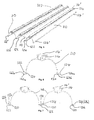
Figure 1 is a top side perspective view of a light fitting according to an embodiment of the invention: -
Figure 2 is a bottom side perspective view of the light fitting ofFigure 1 ; -
Figure 3 is an end view of the light fitting ofFigure 1 ; -
Figure 4 is an end view of the light fitting ofFigure 3 in an alternative configuration; -
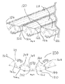
Figure 5 is a bottom side perspective view of a reflector unit of the light fitting ofFigure 1 ; -
Figure 6 is an end cross-sectional view of a reflector housing of the reflector unit ofFigure 5 ; -
Figure 7 is an end cross-sectional view of two adjoined reflector housings ofFigure 6 ; -
Figure 8 is a top side perspective view of two reflector housings partially slid together; -
Figure 9 is an end view of the reflector unit of the light fitting ofFigure 1 ; -
Figure 10 is a top side view of a cable housing for the light fitting ofFigures 1 and 2 ; -
Figure 11 is a top side perspective view of a central member of the cable housing ofFigure 10 ; and -
Figure 12 is a top side perspective view of an outer member of the cable housing ofFigure 10 . - The exemplary embodiments of the present invention will be discussed in detail in relation to a light fitting which provides ready flexibility to adjust a distribution of visible light. However, the teachings, principles and techniques of the present invention are also applicable in other exemplary embodiments. For example, embodiments of the present invention are also applicable to other light fittings which illuminate with non-visible light, such as ultraviolet light or infrared radiation.
-
Figure 1 is a top side prospective view of alight fitting 10 suitable for containing lamps (not shown). The light fitting has areflector unit 100 formed from three adjoinedreflector housings 110, which in this case areU-shaped troughs 110.Light fitting 10 also has on its underside acable housing 200 as shown in the bottom side prospective view offigure 2 . - Each
reflector housing 110 has two lamps and areflector 112, which reflector 112 in this example is an integral part of thereflector housing 110, since the reflector housing is formed of reflector material (extruded aluminium). Eachreflector housing 110 has twoelongate edges 120. Amiddle reflector housing 110 has both of itsedges 120 adjoined toedges 120 ofadjacent reflector housings 110 via hinges (see below). Themiddle reflector housing 110 is pivotably attached to twoouter reflector housings 110 along twopivot axes 130 defined by theedges 120 of themiddle reflector housing 110. Eachreflector housing 110 also has anend cap 140 at each end. The end caps 140 haveelectric terminals 146, each arranged to contact a tubular florescent lamp when the lamp is installed within thelight fitting 10. -
Figure 2 also shows acable channel 114 for routing cables/wiring (connected to the electric terminals 146) substantially down the middle of the underside of eachreflector housing 110. Eachcable channel 114 is shown inFigure 2 covered by cable channel lid 114'. Cables congregate in thecable housing 200 before being connected to an external power supply. Thecable housing 200 has acentre member 210 and twoouter members 220 which move relative to each other to accommodate the pivotal movement of the reflector housings. -
Figure 3 is an end view of thelight fitting 10 in a normal (flat) configuration.Adjacent reflector housings 110 are bridged at theirend caps 140 bycurved plates 144 which fit within complementarycurved grooves 142. -
Figure 4 is an end view of thelight fitting 10 in an alternative configuration, where theouter reflector housings 110 are pivoted outwards about the pivot axes 130. Thecable housing 200 accommodates such outward pivoting. Such outward pivoting allows light from the lamps within eachreflector housing 110 to be distributed more widely, and in some cases more evenly. -
Figure 5 is a bottom side prospective view of areflector unit 100 which forms a part of thelight fitting 10 ofFigures 1 and 2 , and shows how thereflector housings 110 are attached to each other. Themiddle reflector housing 110 has a C-shapedfemale hinge portion 122 on one side and a smaller C-shapedmale hinge portion 124 on the other side. Both of thesehinge portions respective edge 120 of themiddle reflector housing 110. Thefemale hinge portion 122 is attached to anadjacent reflector housing 110 via a complementarymale hinge portion 124 upon theadjacent reflector housing 110. Themale hinge portion 124 of themiddle reflector housing 110 is attached to anotheradjacent reflector housing 110 via afemale hinge portion 122 upon that otheradjacent reflector housing 110. In this example, female and male hinge portions engage each other along their entire length. - One of the
adjacent reflector housings 110 has a terminal female hinge portion 122' whereas the otheradjacent reflector housing 110 has a terminal male hinge portion 124'.Figure 5 also shows thecable channels 114 with lids 114'. -
Figure 6 shows an end cross-sectional view of one of thereflector housings 110. As mentioned, thereflector housing 110 has acable channel 114, afemale hinge portion 122, on one side and amale hinge portion 124 on the other side. Thefemale hinge portion 122 has acavity 122a and a gap 122b, both of which can receive amale hinge portion 124. Themale hinge portion 124 has a male part 124a (in this case a smaller C-shape) and a spacer 124b which causes the male part 124a to protrude slightly from theedge 120. -
Figure 7 shows an end cross-sectional view of twoadjacent reflector housings 110. Importantly the male part 124a is shown to have been received within thecavity 122a, and the gap 122b of thefemale hinge portion 122a acts as a pivot restrictor allowing thereflector housings 110 to pivot relative to each other between two extreme positions, in which the spacer 124b abuts each end of the C-shape of thefemale hinge portion 122. Pivoting takes place about thepivot axis 130 which is where themale hinge portion 124 pivots within thefemale hinge portion 122. -
Figure 8 shows threereflector housings 110 partially slid together along theirrespective edges 120 such that thefemale hinge portion 122 of one of thereflector housings 110 receives along its length themale hinge portion 124 of theother reflector housing 110. Tworeflector housings 110 may be slid together by first inserting a front end of themale hinge portion 124 of onehousing 110 into the rear end of thefemale hinge portion 122 of theother housing 110, and sliding the two reflector housings together until the front end of themale hinge portion 124 meets the front end of the adjacentfemale hinge portion 122. -
Figure 9 is an end view of thereflector unit 100 of thelight fitting 10 ofFigure 1 . Shown in more detail are the end caps 140 upon each reflector housing. Eachend cap 140 has acurved groove 142 to compliment acurved groove 142 upon anadjacent end cap 140. Thecurved plate 144 fits within thegrooves 142 of bothend caps 140, and screws 148, located throughscrew holes 142a and 144a, hold the twoadjacent reflector housings 110 in a particular pivoted position. The combination of thecurved grooves 142,curved plate 144,screw holes 142a, 144a, and screws 148, represent both a lock mechanism and a pivotable adjustment facility. To adjust the relative pivotable position of twoadjacent reflector housings 110 screws must be removed from the screw holes, the reflector housings pivotably adjusted along thepivot axis 130 to a desired position before reinserting the screws through thescrew holes 142a and 144a to lock thereflector housings 110 in a particular pivotable position. The extent of thegrooves 142 can also act as a pivot restrictor which limits the full extent of pivoting about thepivot axis 130. On the inside of the end caps 140 are electrical terminals for connecting to a lamp (not shown). -
Figure 10 shows a top side perspective view of thecable housing 200. Thecable housing 200 has acentre member 210 moveably connected to twoouter members 220. Thecentre member 210 has acavity 212 for cables, which in this example is covered by alid 214. Thecentre member 210 also hasarcuate grooves 216 arrange to receive fasteners to allow moveable attachment of thecentre member 210 to theouter members 220. Theouter members 220 can move within and relative to thecentre member 210 to the extent that the fasteners move within thegrooves 216. Such movement is designed to accommodate pivoting of thereflector housings 110 within thelight fitting 10. In some embodiments thecable housing 200 is adjusted when separate from thereflector housings 110, and then reattached. Thegrooves 216 themselves can be considered a pivot restrictor or part of a pivot restrictor, since the extent to which theouter members 220 move relative to thecentre member 210 will determine the extent of pivoting allowed of thereflector housings 110 within thelight fitting 10. In alternative embodiments, thecable housing 200 itself can comprise the pivotable adjustment facility in that it may contain a motor which moves theouter members 220 relative to thecentre member 210. This in turn causes pivotable movement of thereflector housings 110. -
Figure 11 shows thecentre member 210 in more detail with itsopen cavity 212 arranged in use to hold cables. -
Figure 12 shows in more detail one of theouter members 220 of thecable housing 200. The outer member hasscrew holes 222 to allow the outer member to be pivotally attached to thecentre member 210 with fasteners through theeyes 216 and the corresponding screw holes 222. - In terms of materials, in this example the
reflector housings 110 are formed of a completely integral piece of extruded aluminium. Therefore thereflector 112 is an integral part of eachreflector housing 110. The end caps 140 of eachreflector housing 110 are typically formed of plastics material, suitably rated to withstand heat produced within thelight fittings 10 during normal use. Thecurved plates 144 on the end caps 140 are typically made of plastic. Thecable housing 200 is typically made of steel. - The
reflector unit 100 ofFigure 5 is formed by sliding together threereflector housings 110 as shown inFigure 8 , before fitting theend caps 140. Thecable housing 200 is then fitted with screws to thereflector housings 110 so that, when thereflector housings 110 are pivoted, thecable housing 200 accommodates such pivotable movement. Cables are laid within thecable channels 114 provided upon eachreflector housing 110 before lids 114' are applied. Thecable housing lid 214 is then also fitted. Mounting points upon thecable housing 200 then allow the light fitting to be installed upon such as a ceiling within a shop or factory. The pivoted positions of thereflector housings 110 in this example is predetermined by the locked position of eachcurved plate 144 within its respectivecurved grooves 142. For instance, the light fitting may be pivotably adjusted to provide alight fitting 10 as perFigure 4 so that light is distributed outwards over a wider area than it would be if arranged in a normal position as perFigure 3 . - In use, the
light fitting 10 may be pivotably adjusted using the pivotable adjustment facility of thecurved plate 144. These can be manually adjusted to adjust the distribution of light within a room. - In an alternative embodiment, the
curved plate 144 moves freely in thecurved groove 142, and is not fixed with screws. Instead a motor within the cable housing is remotely controlled to cause pivoting of the reflector housings so thatlight fittings 10 installed in position can be remotely adjusted to achieve optimum distribution of light. - Attention is directed to all papers and documents which are filed concurrently with or previous to this specification in connection with this application and which are open to public inspection with this specification, and the contents of all such papers and documents are incorporated herein by reference.
- All of the features disclosed in this specification (including any accompanying claims, abstract and drawings), and/or all of the steps of any method or process so disclosed, may be combined in any combination, except combinations where at least some of such features and/or steps are mutually exclusive.
- Each feature disclosed in this specification (including any accompanying claims, abstract and drawings) may be replaced by alternative features serving the same, equivalent or similar purpose, unless expressly stated otherwise. Thus, unless expressly stated otherwise, each feature disclosed is one example only of a generic series of equivalent or similar features.
- The invention is not restricted to the details of the foregoing embodiment(s). The invention extends to any novel one, or any novel combination, of the features disclosed in this specification (including any accompanying claims, abstract and drawings), or to any novel one, or any novel combination, of the steps of any method or process so disclosed.
Claims (15)
- A light fitting arrangement (10) including a first and a second reflector housing (110), the first reflector housing (110) being pivotally movable relative to the second reflector housing (110).
- The light fitting arrangement (10) as claimed in claim 1, wherein a first attachment portion (122) of the first reflector housing 9110) is arranged in use to engage a second pivotable attachment portion (124) of the second reflector housing (110), wherein the second pivotable attachment portion (124) is complementary to the first pivotable attachment portion (122).
- The light fitting arrangement (10) as claimed in claim 2, wherein a reflector housing (110) comprises a first and a second pivotable attachment portion (122/124).
- The light fitting arrangement (10) as claimed in any of claims 2 or 3, wherein the first pivotable attachment portion (122) is elongated, and the first pivotable attachment (122) portion of the first reflector housing (110) is arranged to slidably receive the second pivotable attachment (124) portion of the second reflector housing (110) along the length of the elongated first pivotable attachment portion (122).
- The light fitting arrangement (10) as claimed in any preceding claim, comprising a third reflector housing (110) that is pivotally moveable relative to at least one of the first or second reflector housings (110).
- The light fitting arrangement (10) as claimed in any preceding claim, comprising a cable housing (200) for housing cables for powering lights in the reflector housings (110), the cable housing (200) comprising at least two movably linked components which are arranged in use to move with the pivotable movement of the reflector housings (110).
- The light fitting arrangement (10) as claimed in any preceding claim, comprising a pivotable adjustment facility to allow selective pivotable adjustment of adjacent reflector housings (110).
- A reflector housing (110) as described in any of the preceding claims.
- The reflector housing (110) as claimed in claim 8, comprising a reflector (112), wherein the reflector (112) is integral to the reflector housing (110).
- The reflector housing (110) as claimed in any of claims 8 or 9, wherein the reflector housing (110) is a single piece of extruded metal.
- The reflector housing (110) as claimed in any of claims 8 to 10, comprising a first pivotable attachment portion (122), wherein the first pivotable attachment portion (122) is a hinge portion having a substantially C-shape cross section.
- The reflector housing (110) as claimed in any of claims 8 to 11, comprising a first and a second pivotable attachment portion (122/124), wherein the first (122) is complimentary to the second (124).
- A method of manufacturing a light fitting arrangement (10) comprising:pivotally connecting two reflector housings (110) to form the light fitting (10).
- The method as claimed in claim 13, comprising sliding together the two reflector housings (110) to pivotally connect the reflector housings (110).
- A method of lighting an area, comprising:installing a light fitting arrangement (10) as described in any of claims 1 to 7, and pivotably adjusting the relative orientation of reflector housings (110) to produce a desired distribution of light across the area.
Applications Claiming Priority (1)
| Application Number | Priority Date | Filing Date | Title |
|---|---|---|---|
| GBGB0911076.8A GB0911076D0 (en) | 2009-06-26 | 2009-06-26 | Light fitting arrangement |
Publications (2)
| Publication Number | Publication Date |
|---|---|
| EP2267356A1 true EP2267356A1 (en) | 2010-12-29 |
| EP2267356B1 EP2267356B1 (en) | 2014-03-05 |
Family
ID=41008304
Family Applications (1)
| Application Number | Title | Priority Date | Filing Date |
|---|---|---|---|
| EP10166225.2A Not-in-force EP2267356B1 (en) | 2009-06-26 | 2010-06-16 | Light fitting arrangement |
Country Status (2)
| Country | Link |
|---|---|
| EP (1) | EP2267356B1 (en) |
| GB (1) | GB0911076D0 (en) |
Cited By (4)
| Publication number | Priority date | Publication date | Assignee | Title |
|---|---|---|---|---|
| EP2787271A1 (en) * | 2013-04-02 | 2014-10-08 | Dedo Weigert Film GmbH | Lighting device with asymmetric radiation |
| EP3296619A1 (en) * | 2016-09-20 | 2018-03-21 | OSRAM GmbH | A lighting device and corresponding fixing system |
| CN110736077A (en) * | 2019-10-30 | 2020-01-31 | 中铁第四勘察设计院集团有限公司 | Reflecting shade and lamp |
| US20200191369A1 (en) * | 2018-12-17 | 2020-06-18 | MaxLite, Inc. | Adjustable, modular flood light fixture |
Citations (4)
| Publication number | Priority date | Publication date | Assignee | Title |
|---|---|---|---|---|
| JPH07220513A (en) * | 1994-02-02 | 1995-08-18 | Ohbayashi Corp | Luminaire with variable reflector |
| US20020003699A1 (en) * | 2000-05-08 | 2002-01-10 | Shemitz Sylvan R. | Asymmetric distribution luminaire |
| US20030039116A1 (en) * | 2001-08-27 | 2003-02-27 | Guy Belair | Paint booth lighting fixture |
| US20080025021A1 (en) * | 2003-12-23 | 2008-01-31 | Engel Hartmut S | Illumination Device |
-
2009
- 2009-06-26 GB GBGB0911076.8A patent/GB0911076D0/en not_active Ceased
-
2010
- 2010-06-16 EP EP10166225.2A patent/EP2267356B1/en not_active Not-in-force
Patent Citations (4)
| Publication number | Priority date | Publication date | Assignee | Title |
|---|---|---|---|---|
| JPH07220513A (en) * | 1994-02-02 | 1995-08-18 | Ohbayashi Corp | Luminaire with variable reflector |
| US20020003699A1 (en) * | 2000-05-08 | 2002-01-10 | Shemitz Sylvan R. | Asymmetric distribution luminaire |
| US20030039116A1 (en) * | 2001-08-27 | 2003-02-27 | Guy Belair | Paint booth lighting fixture |
| US20080025021A1 (en) * | 2003-12-23 | 2008-01-31 | Engel Hartmut S | Illumination Device |
Cited By (7)
| Publication number | Priority date | Publication date | Assignee | Title |
|---|---|---|---|---|
| EP2787271A1 (en) * | 2013-04-02 | 2014-10-08 | Dedo Weigert Film GmbH | Lighting device with asymmetric radiation |
| EP3296619A1 (en) * | 2016-09-20 | 2018-03-21 | OSRAM GmbH | A lighting device and corresponding fixing system |
| US10451254B2 (en) | 2016-09-20 | 2019-10-22 | Osram Gmbh | Lighting device and corresponding fixing system |
| US20200191369A1 (en) * | 2018-12-17 | 2020-06-18 | MaxLite, Inc. | Adjustable, modular flood light fixture |
| US10995941B2 (en) * | 2018-12-17 | 2021-05-04 | MaxLite, Inc. | Adjustable, modular flood light fixture |
| US11346535B2 (en) | 2018-12-17 | 2022-05-31 | MaxLite, Inc. | Adjustable, modular flood light fixture |
| CN110736077A (en) * | 2019-10-30 | 2020-01-31 | 中铁第四勘察设计院集团有限公司 | Reflecting shade and lamp |
Also Published As
| Publication number | Publication date |
|---|---|
| EP2267356B1 (en) | 2014-03-05 |
| GB0911076D0 (en) | 2009-08-12 |
Similar Documents
| Publication | Publication Date | Title |
|---|---|---|
| US10267463B1 (en) | Adjustable length articulated LED light fixtures | |
| US9494286B2 (en) | Light emitting diode troffer door assembly | |
| US8888335B2 (en) | Lighting system | |
| EP2267356B1 (en) | Light fitting arrangement | |
| US7748868B2 (en) | Recessed luminaire | |
| EP3067616B1 (en) | Recessed track lighting fixture | |
| US6702453B2 (en) | Flexible light fixture | |
| US8235554B2 (en) | LED reflector fixture | |
| CA2346580C (en) | Asymmetric distribution luminaire | |
| CA2945763A1 (en) | Adjustable dual optic directional lamp assembly | |
| US10274171B2 (en) | Adjustable LED light fixture for use in a troffer | |
| KR20170000589A (en) | LED landscape lighting device | |
| EP3679297B1 (en) | Luminaire for mounting on a pole | |
| US7147348B2 (en) | Emergency lighting fixture having adjustable reflector and lamp assembly | |
| KR101580617B1 (en) | Outdoor LED lamp mechanism for easy selection of lighting section | |
| NL2022685B1 (en) | Lighting rail for a line lighting system | |
| DE10132974A1 (en) | Optics for room lights | |
| GB2524999A (en) | Lighting fixtures | |
| CN211976705U (en) | Blackboard lamp with light barrier | |
| KR100558828B1 (en) | Luminaire built-in wiring duct and its construction method | |
| NL2001415C2 (en) | Light fixture structure i.e. ceiling light fixture, has light fixture module arranged at relative position with respect to other light fixture module along longitudinal axis of light fixture, where fixture modules are connected together | |
| US7093957B2 (en) | Adjustable double-arcuate reflector for an emergency lighting fixture |
Legal Events
| Date | Code | Title | Description |
|---|---|---|---|
| PUAI | Public reference made under article 153(3) epc to a published international application that has entered the european phase |
Free format text: ORIGINAL CODE: 0009012 |
|
| AK | Designated contracting states |
Kind code of ref document: A1 Designated state(s): AL AT BE BG CH CY CZ DE DK EE ES FI FR GB GR HR HU IE IS IT LI LT LU LV MC MK MT NL NO PL PT RO SE SI SK SM TR |
|
| AX | Request for extension of the european patent |
Extension state: BA ME RS |
|
| 17P | Request for examination filed |
Effective date: 20110628 |
|
| 17Q | First examination report despatched |
Effective date: 20111122 |
|
| RIC1 | Information provided on ipc code assigned before grant |
Ipc: F21Y 103/00 20060101ALN20130718BHEP Ipc: F21V 7/00 20060101ALI20130718BHEP Ipc: F21S 2/00 20060101AFI20130718BHEP Ipc: F21V 17/10 20060101ALI20130718BHEP Ipc: F21V 17/02 20060101ALI20130718BHEP Ipc: F21V 21/30 20060101ALI20130718BHEP |
|
| GRAP | Despatch of communication of intention to grant a patent |
Free format text: ORIGINAL CODE: EPIDOSNIGR1 |
|
| RIC1 | Information provided on ipc code assigned before grant |
Ipc: F21S 2/00 20060101AFI20130822BHEP Ipc: F21V 17/02 20060101ALI20130822BHEP Ipc: F21V 17/10 20060101ALI20130822BHEP Ipc: F21V 21/30 20060101ALI20130822BHEP Ipc: F21V 7/00 20060101ALI20130822BHEP Ipc: F21Y 103/00 20060101ALN20130822BHEP |
|
| INTG | Intention to grant announced |
Effective date: 20130916 |
|
| GRAS | Grant fee paid |
Free format text: ORIGINAL CODE: EPIDOSNIGR3 |
|
| GRAA | (expected) grant |
Free format text: ORIGINAL CODE: 0009210 |
|
| AK | Designated contracting states |
Kind code of ref document: B1 Designated state(s): AL AT BE BG CH CY CZ DE DK EE ES FI FR GB GR HR HU IE IS IT LI LT LU LV MC MK MT NL NO PL PT RO SE SI SK SM TR |
|
| REG | Reference to a national code |
Ref country code: GB Ref legal event code: FG4D |
|
| REG | Reference to a national code |
Ref country code: CH Ref legal event code: EP |
|
| REG | Reference to a national code |
Ref country code: AT Ref legal event code: REF Ref document number: 655142 Country of ref document: AT Kind code of ref document: T Effective date: 20140315 |
|
| REG | Reference to a national code |
Ref country code: IE Ref legal event code: FG4D |
|
| REG | Reference to a national code |
Ref country code: DE Ref legal event code: R096 Ref document number: 602010013901 Country of ref document: DE Effective date: 20140417 |
|
| REG | Reference to a national code |
Ref country code: AT Ref legal event code: MK05 Ref document number: 655142 Country of ref document: AT Kind code of ref document: T Effective date: 20140305 |
|
| REG | Reference to a national code |
Ref country code: NL Ref legal event code: VDEP Effective date: 20140305 |
|
| PG25 | Lapsed in a contracting state [announced via postgrant information from national office to epo] |
Ref country code: NO Free format text: LAPSE BECAUSE OF FAILURE TO SUBMIT A TRANSLATION OF THE DESCRIPTION OR TO PAY THE FEE WITHIN THE PRESCRIBED TIME-LIMIT Effective date: 20140605 Ref country code: LT Free format text: LAPSE BECAUSE OF FAILURE TO SUBMIT A TRANSLATION OF THE DESCRIPTION OR TO PAY THE FEE WITHIN THE PRESCRIBED TIME-LIMIT Effective date: 20140305 |
|
| REG | Reference to a national code |
Ref country code: LT Ref legal event code: MG4D |
|
| PG25 | Lapsed in a contracting state [announced via postgrant information from national office to epo] |
Ref country code: CY Free format text: LAPSE BECAUSE OF FAILURE TO SUBMIT A TRANSLATION OF THE DESCRIPTION OR TO PAY THE FEE WITHIN THE PRESCRIBED TIME-LIMIT Effective date: 20140305 Ref country code: AT Free format text: LAPSE BECAUSE OF FAILURE TO SUBMIT A TRANSLATION OF THE DESCRIPTION OR TO PAY THE FEE WITHIN THE PRESCRIBED TIME-LIMIT Effective date: 20140305 Ref country code: SE Free format text: LAPSE BECAUSE OF FAILURE TO SUBMIT A TRANSLATION OF THE DESCRIPTION OR TO PAY THE FEE WITHIN THE PRESCRIBED TIME-LIMIT Effective date: 20140305 Ref country code: FI Free format text: LAPSE BECAUSE OF FAILURE TO SUBMIT A TRANSLATION OF THE DESCRIPTION OR TO PAY THE FEE WITHIN THE PRESCRIBED TIME-LIMIT Effective date: 20140305 |
|
| PG25 | Lapsed in a contracting state [announced via postgrant information from national office to epo] |
Ref country code: HR Free format text: LAPSE BECAUSE OF FAILURE TO SUBMIT A TRANSLATION OF THE DESCRIPTION OR TO PAY THE FEE WITHIN THE PRESCRIBED TIME-LIMIT Effective date: 20140305 Ref country code: LV Free format text: LAPSE BECAUSE OF FAILURE TO SUBMIT A TRANSLATION OF THE DESCRIPTION OR TO PAY THE FEE WITHIN THE PRESCRIBED TIME-LIMIT Effective date: 20140305 |
|
| PG25 | Lapsed in a contracting state [announced via postgrant information from national office to epo] |
Ref country code: IS Free format text: LAPSE BECAUSE OF FAILURE TO SUBMIT A TRANSLATION OF THE DESCRIPTION OR TO PAY THE FEE WITHIN THE PRESCRIBED TIME-LIMIT Effective date: 20140705 Ref country code: CZ Free format text: LAPSE BECAUSE OF FAILURE TO SUBMIT A TRANSLATION OF THE DESCRIPTION OR TO PAY THE FEE WITHIN THE PRESCRIBED TIME-LIMIT Effective date: 20140305 Ref country code: EE Free format text: LAPSE BECAUSE OF FAILURE TO SUBMIT A TRANSLATION OF THE DESCRIPTION OR TO PAY THE FEE WITHIN THE PRESCRIBED TIME-LIMIT Effective date: 20140305 Ref country code: BE Free format text: LAPSE BECAUSE OF FAILURE TO SUBMIT A TRANSLATION OF THE DESCRIPTION OR TO PAY THE FEE WITHIN THE PRESCRIBED TIME-LIMIT Effective date: 20140305 Ref country code: BG Free format text: LAPSE BECAUSE OF FAILURE TO SUBMIT A TRANSLATION OF THE DESCRIPTION OR TO PAY THE FEE WITHIN THE PRESCRIBED TIME-LIMIT Effective date: 20140605 Ref country code: NL Free format text: LAPSE BECAUSE OF FAILURE TO SUBMIT A TRANSLATION OF THE DESCRIPTION OR TO PAY THE FEE WITHIN THE PRESCRIBED TIME-LIMIT Effective date: 20140305 Ref country code: RO Free format text: LAPSE BECAUSE OF FAILURE TO SUBMIT A TRANSLATION OF THE DESCRIPTION OR TO PAY THE FEE WITHIN THE PRESCRIBED TIME-LIMIT Effective date: 20140305 |
|
| PG25 | Lapsed in a contracting state [announced via postgrant information from national office to epo] |
Ref country code: ES Free format text: LAPSE BECAUSE OF FAILURE TO SUBMIT A TRANSLATION OF THE DESCRIPTION OR TO PAY THE FEE WITHIN THE PRESCRIBED TIME-LIMIT Effective date: 20140305 Ref country code: PL Free format text: LAPSE BECAUSE OF FAILURE TO SUBMIT A TRANSLATION OF THE DESCRIPTION OR TO PAY THE FEE WITHIN THE PRESCRIBED TIME-LIMIT Effective date: 20140305 Ref country code: SK Free format text: LAPSE BECAUSE OF FAILURE TO SUBMIT A TRANSLATION OF THE DESCRIPTION OR TO PAY THE FEE WITHIN THE PRESCRIBED TIME-LIMIT Effective date: 20140305 |
|
| REG | Reference to a national code |
Ref country code: DE Ref legal event code: R097 Ref document number: 602010013901 Country of ref document: DE |
|
| PG25 | Lapsed in a contracting state [announced via postgrant information from national office to epo] |
Ref country code: PT Free format text: LAPSE BECAUSE OF FAILURE TO SUBMIT A TRANSLATION OF THE DESCRIPTION OR TO PAY THE FEE WITHIN THE PRESCRIBED TIME-LIMIT Effective date: 20140707 |
|
| REG | Reference to a national code |
Ref country code: DE Ref legal event code: R119 Ref document number: 602010013901 Country of ref document: DE |
|
| PLBE | No opposition filed within time limit |
Free format text: ORIGINAL CODE: 0009261 |
|
| STAA | Information on the status of an ep patent application or granted ep patent |
Free format text: STATUS: NO OPPOSITION FILED WITHIN TIME LIMIT |
|
| PG25 | Lapsed in a contracting state [announced via postgrant information from national office to epo] |
Ref country code: DK Free format text: LAPSE BECAUSE OF FAILURE TO SUBMIT A TRANSLATION OF THE DESCRIPTION OR TO PAY THE FEE WITHIN THE PRESCRIBED TIME-LIMIT Effective date: 20140305 Ref country code: MC Free format text: LAPSE BECAUSE OF FAILURE TO SUBMIT A TRANSLATION OF THE DESCRIPTION OR TO PAY THE FEE WITHIN THE PRESCRIBED TIME-LIMIT Effective date: 20140305 Ref country code: LU Free format text: LAPSE BECAUSE OF FAILURE TO SUBMIT A TRANSLATION OF THE DESCRIPTION OR TO PAY THE FEE WITHIN THE PRESCRIBED TIME-LIMIT Effective date: 20140616 |
|
| REG | Reference to a national code |
Ref country code: CH Ref legal event code: PL |
|
| 26N | No opposition filed |
Effective date: 20141208 |
|
| REG | Reference to a national code |
Ref country code: DE Ref legal event code: R097 Ref document number: 602010013901 Country of ref document: DE Effective date: 20141208 |
|
| REG | Reference to a national code |
Ref country code: IE Ref legal event code: MM4A |
|
| REG | Reference to a national code |
Ref country code: DE Ref legal event code: R119 Ref document number: 602010013901 Country of ref document: DE Effective date: 20150101 |
|
| REG | Reference to a national code |
Ref country code: FR Ref legal event code: ST Effective date: 20150227 |
|
| PG25 | Lapsed in a contracting state [announced via postgrant information from national office to epo] |
Ref country code: IT Free format text: LAPSE BECAUSE OF FAILURE TO SUBMIT A TRANSLATION OF THE DESCRIPTION OR TO PAY THE FEE WITHIN THE PRESCRIBED TIME-LIMIT Effective date: 20140305 |
|
| PG25 | Lapsed in a contracting state [announced via postgrant information from national office to epo] |
Ref country code: IE Free format text: LAPSE BECAUSE OF NON-PAYMENT OF DUE FEES Effective date: 20140616 Ref country code: DE Free format text: LAPSE BECAUSE OF NON-PAYMENT OF DUE FEES Effective date: 20150101 Ref country code: LI Free format text: LAPSE BECAUSE OF NON-PAYMENT OF DUE FEES Effective date: 20140630 Ref country code: CH Free format text: LAPSE BECAUSE OF NON-PAYMENT OF DUE FEES Effective date: 20140630 |
|
| PG25 | Lapsed in a contracting state [announced via postgrant information from national office to epo] |
Ref country code: SI Free format text: LAPSE BECAUSE OF FAILURE TO SUBMIT A TRANSLATION OF THE DESCRIPTION OR TO PAY THE FEE WITHIN THE PRESCRIBED TIME-LIMIT Effective date: 20140305 Ref country code: FR Free format text: LAPSE BECAUSE OF NON-PAYMENT OF DUE FEES Effective date: 20140630 |
|
| PG25 | Lapsed in a contracting state [announced via postgrant information from national office to epo] |
Ref country code: MT Free format text: LAPSE BECAUSE OF FAILURE TO SUBMIT A TRANSLATION OF THE DESCRIPTION OR TO PAY THE FEE WITHIN THE PRESCRIBED TIME-LIMIT Effective date: 20140305 |
|
| PG25 | Lapsed in a contracting state [announced via postgrant information from national office to epo] |
Ref country code: SM Free format text: LAPSE BECAUSE OF FAILURE TO SUBMIT A TRANSLATION OF THE DESCRIPTION OR TO PAY THE FEE WITHIN THE PRESCRIBED TIME-LIMIT Effective date: 20140305 |
|
| PG25 | Lapsed in a contracting state [announced via postgrant information from national office to epo] |
Ref country code: GR Free format text: LAPSE BECAUSE OF FAILURE TO SUBMIT A TRANSLATION OF THE DESCRIPTION OR TO PAY THE FEE WITHIN THE PRESCRIBED TIME-LIMIT Effective date: 20140606 |
|
| PG25 | Lapsed in a contracting state [announced via postgrant information from national office to epo] |
Ref country code: TR Free format text: LAPSE BECAUSE OF FAILURE TO SUBMIT A TRANSLATION OF THE DESCRIPTION OR TO PAY THE FEE WITHIN THE PRESCRIBED TIME-LIMIT Effective date: 20140305 Ref country code: HU Free format text: LAPSE BECAUSE OF FAILURE TO SUBMIT A TRANSLATION OF THE DESCRIPTION OR TO PAY THE FEE WITHIN THE PRESCRIBED TIME-LIMIT; INVALID AB INITIO Effective date: 20100616 |
|
| PGFP | Annual fee paid to national office [announced via postgrant information from national office to epo] |
Ref country code: GB Payment date: 20170627 Year of fee payment: 8 |
|
| PG25 | Lapsed in a contracting state [announced via postgrant information from national office to epo] |
Ref country code: MK Free format text: LAPSE BECAUSE OF FAILURE TO SUBMIT A TRANSLATION OF THE DESCRIPTION OR TO PAY THE FEE WITHIN THE PRESCRIBED TIME-LIMIT Effective date: 20140305 |
|
| PG25 | Lapsed in a contracting state [announced via postgrant information from national office to epo] |
Ref country code: AL Free format text: LAPSE BECAUSE OF FAILURE TO SUBMIT A TRANSLATION OF THE DESCRIPTION OR TO PAY THE FEE WITHIN THE PRESCRIBED TIME-LIMIT Effective date: 20140305 |
|
| GBPC | Gb: european patent ceased through non-payment of renewal fee |
Effective date: 20180616 |
|
| PG25 | Lapsed in a contracting state [announced via postgrant information from national office to epo] |
Ref country code: GB Free format text: LAPSE BECAUSE OF NON-PAYMENT OF DUE FEES Effective date: 20180616 |