EP2267322A1 - Bolt and nut with anti-loosening mechanism - Google Patents
Bolt and nut with anti-loosening mechanism Download PDFInfo
- Publication number
- EP2267322A1 EP2267322A1 EP08721608A EP08721608A EP2267322A1 EP 2267322 A1 EP2267322 A1 EP 2267322A1 EP 08721608 A EP08721608 A EP 08721608A EP 08721608 A EP08721608 A EP 08721608A EP 2267322 A1 EP2267322 A1 EP 2267322A1
- Authority
- EP
- European Patent Office
- Prior art keywords
- bolt
- nut
- grooves
- knob
- tip
- Prior art date
- Legal status (The legal status is an assumption and is not a legal conclusion. Google has not performed a legal analysis and makes no representation as to the accuracy of the status listed.)
- Granted
Links
Images



Classifications
-
- F—MECHANICAL ENGINEERING; LIGHTING; HEATING; WEAPONS; BLASTING
- F16—ENGINEERING ELEMENTS AND UNITS; GENERAL MEASURES FOR PRODUCING AND MAINTAINING EFFECTIVE FUNCTIONING OF MACHINES OR INSTALLATIONS; THERMAL INSULATION IN GENERAL
- F16B—DEVICES FOR FASTENING OR SECURING CONSTRUCTIONAL ELEMENTS OR MACHINE PARTS TOGETHER, e.g. NAILS, BOLTS, CIRCLIPS, CLAMPS, CLIPS OR WEDGES; JOINTS OR JOINTING
- F16B39/00—Locking of screws, bolts or nuts
- F16B39/02—Locking of screws, bolts or nuts in which the locking takes place after screwing down
-
- F—MECHANICAL ENGINEERING; LIGHTING; HEATING; WEAPONS; BLASTING
- F16—ENGINEERING ELEMENTS AND UNITS; GENERAL MEASURES FOR PRODUCING AND MAINTAINING EFFECTIVE FUNCTIONING OF MACHINES OR INSTALLATIONS; THERMAL INSULATION IN GENERAL
- F16B—DEVICES FOR FASTENING OR SECURING CONSTRUCTIONAL ELEMENTS OR MACHINE PARTS TOGETHER, e.g. NAILS, BOLTS, CIRCLIPS, CLAMPS, CLIPS OR WEDGES; JOINTS OR JOINTING
- F16B35/00—Screw-bolts; Stay-bolts; Screw-threaded studs; Screws; Set screws
- F16B35/04—Screw-bolts; Stay-bolts; Screw-threaded studs; Screws; Set screws with specially-shaped head or shaft in order to fix the bolt on or in an object
-
- F—MECHANICAL ENGINEERING; LIGHTING; HEATING; WEAPONS; BLASTING
- F16—ENGINEERING ELEMENTS AND UNITS; GENERAL MEASURES FOR PRODUCING AND MAINTAINING EFFECTIVE FUNCTIONING OF MACHINES OR INSTALLATIONS; THERMAL INSULATION IN GENERAL
- F16B—DEVICES FOR FASTENING OR SECURING CONSTRUCTIONAL ELEMENTS OR MACHINE PARTS TOGETHER, e.g. NAILS, BOLTS, CIRCLIPS, CLAMPS, CLIPS OR WEDGES; JOINTS OR JOINTING
- F16B39/00—Locking of screws, bolts or nuts
- F16B39/02—Locking of screws, bolts or nuts in which the locking takes place after screwing down
- F16B39/10—Locking of screws, bolts or nuts in which the locking takes place after screwing down by a plate, spring, wire or ring immovable with regard to the bolt or object and mainly perpendicular to the axis of the bolt
-
- F—MECHANICAL ENGINEERING; LIGHTING; HEATING; WEAPONS; BLASTING
- F16—ENGINEERING ELEMENTS AND UNITS; GENERAL MEASURES FOR PRODUCING AND MAINTAINING EFFECTIVE FUNCTIONING OF MACHINES OR INSTALLATIONS; THERMAL INSULATION IN GENERAL
- F16B—DEVICES FOR FASTENING OR SECURING CONSTRUCTIONAL ELEMENTS OR MACHINE PARTS TOGETHER, e.g. NAILS, BOLTS, CIRCLIPS, CLAMPS, CLIPS OR WEDGES; JOINTS OR JOINTING
- F16B31/00—Screwed connections specially modified in view of tensile load; Break-bolts
- F16B31/02—Screwed connections specially modified in view of tensile load; Break-bolts for indicating the attainment of a particular tensile load or limiting tensile load
-
- F—MECHANICAL ENGINEERING; LIGHTING; HEATING; WEAPONS; BLASTING
- F16—ENGINEERING ELEMENTS AND UNITS; GENERAL MEASURES FOR PRODUCING AND MAINTAINING EFFECTIVE FUNCTIONING OF MACHINES OR INSTALLATIONS; THERMAL INSULATION IN GENERAL
- F16B—DEVICES FOR FASTENING OR SECURING CONSTRUCTIONAL ELEMENTS OR MACHINE PARTS TOGETHER, e.g. NAILS, BOLTS, CIRCLIPS, CLAMPS, CLIPS OR WEDGES; JOINTS OR JOINTING
- F16B39/00—Locking of screws, bolts or nuts
- F16B39/02—Locking of screws, bolts or nuts in which the locking takes place after screwing down
- F16B39/04—Locking of screws, bolts or nuts in which the locking takes place after screwing down with a member penetrating the screw-threaded surface of at least one part, e.g. a pin, a wedge, cotter-pin, screw
-
- F—MECHANICAL ENGINEERING; LIGHTING; HEATING; WEAPONS; BLASTING
- F16—ENGINEERING ELEMENTS AND UNITS; GENERAL MEASURES FOR PRODUCING AND MAINTAINING EFFECTIVE FUNCTIONING OF MACHINES OR INSTALLATIONS; THERMAL INSULATION IN GENERAL
- F16B—DEVICES FOR FASTENING OR SECURING CONSTRUCTIONAL ELEMENTS OR MACHINE PARTS TOGETHER, e.g. NAILS, BOLTS, CIRCLIPS, CLAMPS, CLIPS OR WEDGES; JOINTS OR JOINTING
- F16B39/00—Locking of screws, bolts or nuts
- F16B39/22—Locking of screws, bolts or nuts in which the locking takes place during screwing down or tightening
- F16B39/28—Locking of screws, bolts or nuts in which the locking takes place during screwing down or tightening by special members on, or shape of, the nut or bolt
- F16B39/282—Locking by means of special shape of work-engaging surfaces, e.g. notched or toothed nuts
Definitions
- the present invention relates to a set of a bolt and a nut. Especially, the present invention relates to a set of a bolt and a nut having a rotation prohibiting mechanism.
- the prohibition of the relative rotation between the bolt and the nut can be accomplished by providing a foldable part, at a tip of the bolt, which can be folded around an axis extending perpendicular to the bolt axis, and providing a groove, at a tip surface of the nut, which receives the foldable part.
- a lock member 46 is provided at the tip of a bolt 40.
- the lock member 46 swings with a pin 42 which extends perpendicular to a bolt axis 40x as a center.
- a groove 44a which receives the lock member 46 is provided at the tip surface of a nut 44.
- the tip surface corresponds to a surface from which the lock member 46 provided at the tip of the bolt 40 projects out.
- the bolt 40 can be screwed into the nut 44 by aligning the lock member 46 with the bolt axis 40x.
- the lock member 46 is swung with being centered at the pin 42 and is fitted into the groove 44a after the nut 44 is screwed into until a predetermined depth. Then, a relative rotation between the bolt 40 and the nut 44 is prohibited and a rotation prohibition of the bolt 40 and nut 44 is accomplished.
- the rotation prohibition can be achieved by above-mentioned technique.
- a relative angle between the bolt and the nut for prohibiting the rotation is limited.
- the relative rotation between the bolt and the nut can be prohibited only at the one position among 360 degrees.
- a plurality of grooves 44a is provided with being arranged radially, the number of angles at which the relative rotation are prohibited increases. For example, as shown in Fig. 6A , when the two grooves are arranged in line, the rotation prohibition can be achieved at every 180 degrees. As shown in Fig. 6B , when the eight grooves are arranged radially the rotation prohibition can be achieved at every 45 degrees.
- the torque management between the bolt 40 and the nut 44 is severe, it is favorable to increase the number of grooves.
- the torque at the angle at which the rotation prohibition is realized may be either too strong or too weak.
- No groove may exist corresponding to an angle at which an appropriate torque can be realized, and thus, there may be a situation where the rotation prohibition can not be achieved at an angle at which an appropriate torque can be realized.
- Fig. 6B if a plurality of grooves is provided with being arranged radially, possibility of prohibiting the rotation at an angle at which the appropriate torque is achieved may increase.
- the rotation prohibition can be achieved in every 45 degrees relative rotation between the bolt and the nut.
- the rotation prohibition has a 45 degrees resolution.
- the 45 degrees resolution may not be enough.
- the torque at the angle at which the rotation prohibition is realized is either too strong or too weak, and thus an appropriate torque can not be achieved.
- the requirement for the torque management increases, there is a need to increase the resolution of the angle at which the rotation prohibition can be realized by increasing the number of the grooves.
- the number of grooves having an appropriate width that can be formed on the nut having a predetermined size is limited. There may be a case where the number of grooves needed for achieving the required resolution can not be formed.
- the present invention provides a technique to realize higher resolution than the resolution simply calculated from the number of grooves.
- a bolt according to the present invention comprises a foldable part at the tip of the bolt.
- the foldable part can be folded around an axis extending perpendicular to a bolt axis.
- the foldable part can be folded to either sides from a center which corresponds to the bolt axis.
- the nut according to the present invention has grooves at a tip surface of the nut. Each of the grooves can receive the foldable part. It is noted that the tip surface of the nut corresponds to a surface from which the tip of the bolt projects out when tightening the bolt and the nut to each other.
- a number of the grooves is an odd number.
- the grooves are arranged radially with respect to a center at the screw hole of the nut.
- the grooves are also arranged radially with equal angular intervals.
- a case where seven grooves are arranged radially with equal angular intervals will be explained as an example.
- the angle between adjacent two grooves is about 51.4 degrees, and this angle is to be an expected angular resolution of the rotation prohibition according to the conventional technique.
- the expected angular resolution can be halved (i.e. 25.7 degrees) according to the present invention.
- the foldable part of the bolt is folded to a direction opposite from the direction to which the foldable part had been folded, the foldable part can be inserted into a groove located at the opposite side. If the bolt has the even-number of grooves, the above mentioned relation can not be achieved.
- the angular resolution of rotation prohibition can be doubled by employing the add-numbered grooves. A 60 degrees resolution can be achieved when three grooves are provided; a 36 degrees resolution can be achieved when five grooves are provided; and a 25.7 degree-resolution can be achieved when seven grooves are provided.
- the above mentioned set of bolt and nut has an advantage especially in a case where the user tightens the bolt and nut directly by hands without any tools.
- a tightening torque may be low, and thus, the bolt and nut tend to loosen easily.
- the rotation-prohibition mechanism is useful for such a situation.
- the above mentioned set of bolt and nut is especially useful for fixing a device to a body of airplane.
- the airplane is vibratory and thus, the bolt and nut tend to loosen easily.
- maintenance and inspection have to be frequently conducted for an airplane, thus the bolt and nut may often need to be loosened.
- the bolt and nut according to the present invention for fixing a device to the body of the airplane, the bolt and nut does not easily loosen under vibration, and does not undermine work efficiency for the maintenance.
- a clutch mechanism may be provided so that a torque larger than a predetermined value is not applied between the bolt and nut.
- a clutch mechanism for preventing an excessive tightening may be provided in this case, a knob may be provided in addition to the nut. If a clutch mechanism which allows free rotation when an excessive torque is applied between the nut and the knob is provided, the excessive tightening may be prevented.
- a predetermined torque may be maintained by engaging the rotation prohibiting mechanism after tightening the nut and knob until they rotate and slip relative to each other.
- the bolt of the present invention may be configured to swing with respect to a member to which the bolt is attached.
- the bolt configured to swing itself has an advantage that the device to be fixed by the bolt and nut may easily be attached or detached.
- the set of bolt and nut according to the present invention provides a resolution of the rotation prohibition higher than the resolution simply calculated from the number of grooves for the rotation prohibition. Further, the set of bolt and nut according to the present invention can satisfy both of the torque management and the rotation prohibition mechanism.
- FIG. 1 shows an exploded perspective view of a set of a bolt and a nut.
- a reference numeral 2 denotes a support in which a base 2a is fixed to a body of an airplane. More precisely, the base 2a of the support 2 is fixed to a rack which is fixed to the body of the airplane.
- a groove 2f is formed on the support 2 along an axis of the support 2. The groove 2f opens toward an upper side.
- a reference numeral 2c is a brim to which a flange 36 of an electronic device for the airplane is fixed with a nut 18.
- a through hole 2b is formed on each of side walls which define the groove 2f.
- a bolt 20 is stored in the groove 2f.
- a through hole 20b is formed at an base end of the bolt 20.
- a threaded ridge 20a is formed on an outer periphery of the bolt 20 at a middle portion thereof.
- a though hole 20c is formed at a tip end of the bolt 20.
- a pin 34 is inserted in the though hole 20b of the bolt 20.
- the pin 34 is inserted into the though holes 2b of the support 2 and fixed.
- the bolt 20 can swing around the pin 34 (refer to an arrow S).
- the bolt 20 can take a position at which the bolt 20 extends in groove 2f along an axis center 2x, and can rotate upward for 90 degrees and extend along a vertical line 2y.
- a partial spherical surface 2e having a center near the through hole 2b is formed at the tip of the support 2.
- a cylindrical portion 2d is formed at a rear side of the partial spherical surface 2e.
- the groove 2f extends along the axis center line 2x of the support 2 and extends through the brim 2c, the cylindrical portion 2d, and the partial spherical surface 2e.
- a lock member 30 is attached at the tip end of the bolt 20 by a pin 32 which extends perpendicular to a volt axis 20x.
- the lock member 30 is able to swing around the pin 32.
- the lock member 30 is able to take a position at which a longitudinal direction of the lock member 30 extends along the bolt axis 20x, a position at which the longitudinal direction of the lock member 30 extends upward vertically, and a position at which the longitudinal direction of the lock member 30 extends downward vertically. That is to say, the lock member 30 is able to swing from the position at which the longitudinal direction of the lock member 30 extends along the bolt axis 20x to upward (denoted by the arrow U) as well as downward (denoted by the arrow D).
- the lock member 30 has convex portions 30a and 30b which are inserted into grooves 18a ⁇ 18g described later.
- the convex portion 30a is formed on a front side of the lock member 30 and the convex portion 30b is formed on a backside of the lock member 30.
- the convex portion 30b is inserted into one of the grooves 18 a ⁇ 18g described later.
- the convex portion 30a is inserted into one of the grooves 18a ⁇ 18g described later.
- the lock member 30 is inserted into one of the grooves 18a ⁇ 18g when it swings either upward or downward. Washers 22, 24, 26, 28, and so on are provided between the lock member 30 and the bolt 20.
- the lock member 30 corresponds to a foldable part at the tip of the bolt 20.
- the foldable part is able to swing around the axis 32 which extends perpendicular to the bolt axis 20x.
- the bolt 30 extends through members denoted by numerals 4 to 18 in Fig. 1 .
- the knob 18 is provided to the bolt 20 where the washer 28 prevents the knob 18 from dropping out from the bolt 20.
- the numeral 4 in the drawings is a holder. As shown in Fig. 2 , a contact surface 4a is provided at a base side of the holder 4. The contact surface 4a sandwiches the flange 36 with the brim 2c. A concave portion (not shown) is formed at the center of the contact surface 4a. The concave portion forms a partial spherical surface having its center near the through hole 2b. The concave portion of a partial spherical surface can slip with respect to the partial spherical surface 2e.
- the holder 4 is able to move up or down with centering at the through hole 2b and along the partial spherical surface 2e.
- a tip surface 4b of the holder 4 is flat.
- the numerals 6, 8 in the drawings denote washers.
- the numeral 10 in the drawings denotes a needle roller and a cage, and they facilitate smooth rotation of the nut 12.
- a female screw thread is formed at the through hole of the nut 12 which is screwed with the threaded ridge 20a of the bolt.
- the bolt 20 is fixed with the position at which the bolt axis 20x is aligned with the axis center line 2x of the support 2.
- the flange 36 of the electric device for the airplane is fixed as shown in Fig. 2 .
- the nut 12 is stored in the knob 18. Thus, the nut 12 can not be rotated directly.
- the clutch mechanism 15 is provided between the nut 12 and the knob 18.
- the clutch mechanism 15 is configured by six concave portions 12a formed on a tip surface of the nut 12, the three balls 14, and the three springs 16.
- the three springs 16 are pressed onto the balls 14 by the knob 16, and the balls 14 are pressed onto the concave portions 12a.
- the clutch mechanism 15 rotates the nut 12 in the clockwise direction when the knob 18 is rotated in the clockwise direction.
- a resisting force against the nut 12 reaches a predetermined torque, the nut 12 does not rotate further even if the knob 18 rotates because the balls 14 pop out from the concave portions 12a.
- the clutch mechanism 15 prevents the tightening torque for the nut 12 from exceeding a predetermined value. On the other hand the clutch mechanism 15 rotates the nut 12 in a counter clockwise direction when the knob 18 rotates in the counter clockwise direction. The clutch mechanism 15 is not released by the rotation to the direction which the nut 12 loosens.
- the seven grooves 18a - 18g which receive the lock member 30 are formed at the tip surface of the knob 18.
- the tip surface is a surface of the knob 18 from which side the lock member 30 projects out when the bolt 20 and the nut 12 are tightened to each other.
- the number of the grooves is an odd number.
- the grooves are formed by being arranged radially with respect to the center hole of the knob 18.
- the grooves are also arranged with equal angular intervals.
- Fig. 2 shows a configuration in which the convex portion 30b of the lock member 30 is inserted in the groove 18a.
- Fig. 4A depicts a configuration in which the lock member 30 is folded upward and the convex portion 30b is inserted in the groove 18a. As shown in Fig.
- the bolt 20 should be rotated for 51.4 degrees from a position shown in Fig. 4A in order to achieve the rotation prohibition by inserting the convex portion 30b into the groove 18g.
- a resolution for the rotation prohibition is 51.4 degrees when the resolution is simply calculated from the number of grooves.
- the convex portion 30a can be inserted into one of the grooves 18 by folding the lock member 30 downward.
- the convex portion 30a can be inserted into the groove 18d and thus, the rotation prohibition can be achieved by rotating the bolt 20 for 25.7 degrees from a position shown in Fig. 4A . Therefore, the resolution for the rotation prohibition becomes 25.7 degrees.
- the resolution for the rotation prohibition can be achieved with a step width order not of (360 degrees)/(the number of grooves) but of (360 degrees)/(twice of the number of the grooves), according to the configuration in which the odd-numbered grooves are arranged radially with equal angular intervals and the lock member 30 can be inserted into the groove by folding the lock member 30 either upward or downward.
- Figs. 3A - 3C schematically show an action of the clutch 15.
- Fig. 3A shows a situation in which the nut 12 is tightened by rotating the knob 18 in the clockwise direction with a small torque.
- Fig. 3B shows a situation in which the resisting force against the nut 12 reaches the predetermined torque, and a toque larger than the predetermined torque is applied to the knob 18. In this situation, the ball 14 pops out from a shallow concave portion 12c and thus, the nut 12 no longer rotate even if the knob 18 rotates.
- the clutch mechanism 15 prevents the tightening torque for the nut 12 from exceeding the predetermined value. In the actual situation of operation, the user tightens the knob 18 until the knob 18 rotates freely with respect to the nut 12.
- the user tightens the knob 18 until the ball 14 pops out from the shallow concave portion 12c and drops into the adjacent concave portion 12a.
- the user can be clearly aware of an occurrence, though his or her hand, of the ball popping out from the shallow concave portion 12c and dropping into the adjacent concave portion 12a.
- the nut 12 and the bolt 20 are tightened with the predetermined torque.
- the user can confirm, by a feeling of his or her own hand, that the bolt and the nut are surely tightened with the predetermined torque.
- Fig. 3C shows a situation in which the nut 12 is loosened by rotating the knob 18 in the counter clockwise direction.
- the ball 14 engages with a deep groove 12b, and thus, the ball 14 is not able to pop up from the concave portion 12b even if the large torque is applied to the knob 18.
- the clutch mechanism 15 is not released by the rotation to the direction which the nut 12 loosens.
- the flange 36 of the electric device for the airplane opens at the same direction as the opening of the groove 2f. Therefore, the bolt 20 can be swung upward by loosening the knob 18 and the nut 12 while the support 2 supports the electric device for the airplane. In this situation, the flange 36 of the electric device for the airplane can be easily detached from the support 2. As shown in Figs. 1 and 2 , a hole 36a in which the cylindrical portion 2d of the support 2 extends through is provided on the flange 36. Further, a slit 36b through which the bolt 20 extends is provided. Since the slit 36b is provided, the bolt 20 can be swung vertically upward while the support 2 is inserted into the flange 36.
- the bracket 36 When the bolt 20 is swung vertically upward, the bracket 36 can move forward to the front of the support 2.
- the slit 36b is too narrow for the cylindrical portion 2d to cross over. Nevertheless, the flange 36 can be detached from the support 2.
- the hole 36a is not formed with a U-shape but formed with a C-shape having the narrow slit 36b. This configuration provides a wider contact surface between the brim 2c and the flange 36. Due to this configuration, the electric device for the airplane can be fixed firmly. Further, the flange 36 is not dropped from the support 2 unless the bolt 20 is swung vertically upward.
- the flange 36 which has been detached from the support 2 can be easily attached to the support 2.
- the cylindrical portion 2d can be inserted into the hole 36a by utilizing the partial spherical surface 2e.
- the flange 36 opens at the same direction as the opening of the groove 2f by the slit 36b. Therefore, while maintaining the situation, the bolt 20 can be aligned with the support 2.
- the flange 36 of the electric device for the airplane can be fixed by the bolt 20 and the nut 12.
- dimples 19 are provided around a periphery of the knob 18 so that the user can easily grasp the knob 18. The user can tighten the knob 18 by his or her hand without using any tools until the clutch mechanism 15 rotates with slip.
- the nut 12 and the knob 18 are provided separately in order to utilize the clutch mechanism 15 which controls tightening torque.
- the nut 12 and the knob 18 rotate together when loosening the nut 12.
- the nut 12 is integral with the knob 18 and the knob can be regarded as a part of the nut.
- the expression of "grooves are formed on the nut" in the CLAIMS means that grooves are formed either on the nut or the knob when the clutch mechanism is employed.
- the bolt and the nut swing together with respect to the support 2. Therefore, the work for detaching/attaching the device from/to the bolt 20 can be facilitated.
- the present invention can also be applied to a bolt which does not swing, and it is preferable to provide the lock member to the bolt which does not swing.
Landscapes
- Engineering & Computer Science (AREA)
- General Engineering & Computer Science (AREA)
- Mechanical Engineering (AREA)
- Details Of Spanners, Wrenches, And Screw Drivers And Accessories (AREA)
- Pivots And Pivotal Connections (AREA)
Abstract

Description
- The present invention relates to a set of a bolt and a nut. Especially, the present invention relates to a set of a bolt and a nut having a rotation prohibiting mechanism.
- There exists a requirement to prohibit a relative rotation between a bolt and a nut while tightening the bolt and the nut to each other.
- The prohibition of the relative rotation between the bolt and the nut can be accomplished by providing a foldable part, at a tip of the bolt, which can be folded around an axis extending perpendicular to the bolt axis, and providing a groove, at a tip surface of the nut, which receives the foldable part.
For example, as shown inFig. 5 , alock member 46 is provided at the tip of abolt 40. Thelock member 46 swings with apin 42 which extends perpendicular to abolt axis 40x as a center. On the other hand, agroove 44a which receives thelock member 46 is provided at the tip surface of anut 44. Here, the tip surface corresponds to a surface from which thelock member 46 provided at the tip of thebolt 40 projects out. Thebolt 40 can be screwed into thenut 44 by aligning thelock member 46 with thebolt axis 40x. Thelock member 46 is swung with being centered at thepin 42 and is fitted into thegroove 44a after thenut 44 is screwed into until a predetermined depth. Then, a relative rotation between thebolt 40 and thenut 44 is prohibited and a rotation prohibition of thebolt 40 andnut 44 is accomplished. - The rotation prohibition can be achieved by above-mentioned technique. However, in the example shown in
Fig. 5 , a relative angle between the bolt and the nut for prohibiting the rotation is limited. By the configuration ofFig. 5 , the relative rotation between the bolt and the nut can be prohibited only at the one position among 360 degrees.
If a plurality ofgrooves 44a is provided with being arranged radially, the number of angles at which the relative rotation are prohibited increases. For example, as shown inFig. 6A , when the two grooves are arranged in line, the rotation prohibition can be achieved at every 180 degrees. As shown inFig. 6B , when the eight grooves are arranged radially the rotation prohibition can be achieved at every 45 degrees. - When the torque management between the
bolt 40 and thenut 44 is severe, it is favorable to increase the number of grooves. For example, as shown inFig. 5 , in a case where the rotation prohibition can be achieved at only one position, the torque at the angle at which the rotation prohibition is realized may be either too strong or too weak. No groove may exist corresponding to an angle at which an appropriate torque can be realized, and thus, there may be a situation where the rotation prohibition can not be achieved at an angle at which an appropriate torque can be realized. As shown inFig. 6B , if a plurality of grooves is provided with being arranged radially, possibility of prohibiting the rotation at an angle at which the appropriate torque is achieved may increase. - As shown in
Fig. 6B , if the eight grooves are arranged radially, the rotation prohibition can be achieved in every 45 degrees relative rotation between the bolt and the nut. This means, in other words, the rotation prohibition has a 45 degrees resolution.
In a case where a strict torque management is required, the 45 degrees resolution may not be enough. With the 45 degrees resolution provided, there may be a case where the torque at the angle at which the rotation prohibition is realized is either too strong or too weak, and thus an appropriate torque can not be achieved. As the requirement for the torque management increases, there is a need to increase the resolution of the angle at which the rotation prohibition can be realized by increasing the number of the grooves.
However, the number of grooves having an appropriate width that can be formed on the nut having a predetermined size is limited. There may be a case where the number of grooves needed for achieving the required resolution can not be formed. - The present invention provides a technique to realize higher resolution than the resolution simply calculated from the number of grooves.
- A bolt according to the present invention comprises a foldable part at the tip of the bolt. The foldable part can be folded around an axis extending perpendicular to a bolt axis. The foldable part can be folded to either sides from a center which corresponds to the bolt axis. The nut according to the present invention has grooves at a tip surface of the nut. Each of the grooves can receive the foldable part. It is noted that the tip surface of the nut corresponds to a surface from which the tip of the bolt projects out when tightening the bolt and the nut to each other. A number of the grooves is an odd number. The grooves are arranged radially with respect to a center at the screw hole of the nut. The grooves are also arranged radially with equal angular intervals.
A case where seven grooves are arranged radially with equal angular intervals will be explained as an example. In this case, the angle between adjacent two grooves is about 51.4 degrees, and this angle is to be an expected angular resolution of the rotation prohibition according to the conventional technique. However, the expected angular resolution can be halved (i.e. 25.7 degrees) according to the present invention.
When the bolt rotates for 25.7 degrees from a position where the foldable part can be inserted into one of the grooves, the foldable part can not be inserted into the groove adjacent to the groove in which the foldable part had been inserted. However, if the foldable part of the bolt is folded to a direction opposite from the direction to which the foldable part had been folded, the foldable part can be inserted into a groove located at the opposite side. If the bolt has the even-number of grooves, the above mentioned relation can not be achieved. However, the angular resolution of rotation prohibition can be doubled by employing the add-numbered grooves. A 60 degrees resolution can be achieved when three grooves are provided; a 36 degrees resolution can be achieved when five grooves are provided; and a 25.7 degree-resolution can be achieved when seven grooves are provided. - The above mentioned set of bolt and nut has an advantage especially in a case where the user tightens the bolt and nut directly by hands without any tools. In the case where the user tightens the bolt and nut directly by hands without any tools, a tightening torque may be low, and thus, the bolt and nut tend to loosen easily. The rotation-prohibition mechanism is useful for such a situation.
- Further, the above mentioned set of bolt and nut is especially useful for fixing a device to a body of airplane. The airplane is vibratory and thus, the bolt and nut tend to loosen easily. On the other hand, maintenance and inspection have to be frequently conducted for an airplane, thus the bolt and nut may often need to be loosened. By using the bolt and nut according to the present invention for fixing a device to the body of the airplane, the bolt and nut does not easily loosen under vibration, and does not undermine work efficiency for the maintenance.
- According to the present invention, a clutch mechanism may be provided so that a torque larger than a predetermined value is not applied between the bolt and nut. In other words, it is preferable to provide a clutch mechanism for preventing an excessive tightening. In this case, a knob may be provided in addition to the nut. If a clutch mechanism which allows free rotation when an excessive torque is applied between the nut and the knob is provided, the excessive tightening may be prevented. In this case, a predetermined torque may be maintained by engaging the rotation prohibiting mechanism after tightening the nut and knob until they rotate and slip relative to each other.
- The bolt of the present invention may be configured to swing with respect to a member to which the bolt is attached. The bolt configured to swing itself has an advantage that the device to be fixed by the bolt and nut may easily be attached or detached.
- The set of bolt and nut according to the present invention provides a resolution of the rotation prohibition higher than the resolution simply calculated from the number of grooves for the rotation prohibition. Further, the set of bolt and nut according to the present invention can satisfy both of the torque management and the rotation prohibition mechanism.
-
-
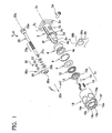
Fig. 1 shows an exploded perspective view of a set of bolt and nut in an embodiment. -
Fig. 2 shows a perspective view of the set of bolt and nut in the embodiment. -
Fig. 3A to Fig. 3C schematically show the configuration of a clutch mechanism provided between the knob and the nut in the embodiment. -
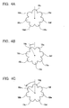
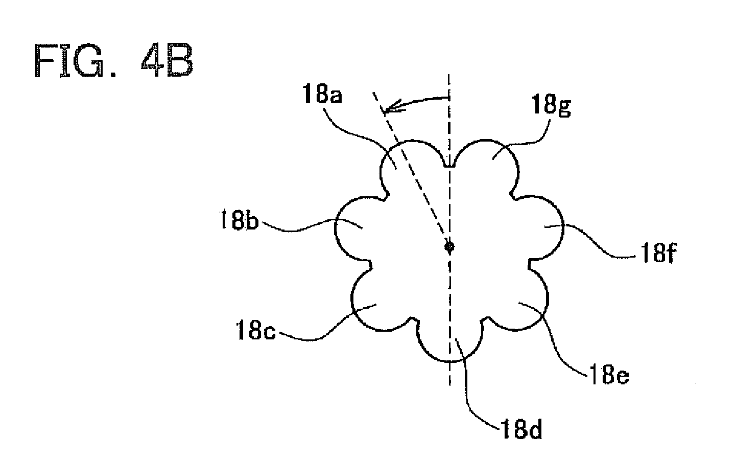
Fig. 4A to Fig. 4C show front views of grooves for rotation-prohibition. -
Fig. 5 schematically shows the conventional bolt and nut. -
Fig. 6A and Fig. 6B schematically show the conventional nut. - Features of each embodiment are listed below.
- (First feature) A bolt is attached to a body of an airplane.
- (Second feature) The bolt swings with respect to the body of the airplane.
- (Third feature) A nut is grasped and rotated by a human hand.
-
Fig. 1 shows an exploded perspective view of a set of a bolt and a nut. Areference numeral 2 denotes a support in which abase 2a is fixed to a body of an airplane. More precisely, thebase 2a of thesupport 2 is fixed to a rack which is fixed to the body of the airplane. Agroove 2f is formed on thesupport 2 along an axis of thesupport 2. Thegroove 2f opens toward an upper side. Areference numeral 2c is a brim to which aflange 36 of an electronic device for the airplane is fixed with anut 18. A throughhole 2b is formed on each of side walls which define thegroove 2f.
Abolt 20 is stored in thegroove 2f. A throughhole 20b is formed at an base end of thebolt 20. A threadedridge 20a is formed on an outer periphery of thebolt 20 at a middle portion thereof. A thoughhole 20c is formed at a tip end of thebolt 20. Apin 34 is inserted in the thoughhole 20b of thebolt 20. Thepin 34 is inserted into the thoughholes 2b of thesupport 2 and fixed. Thebolt 20 can swing around the pin 34 (refer to an arrow S). Thebolt 20 can take a position at which thebolt 20 extends ingroove 2f along anaxis center 2x, and can rotate upward for 90 degrees and extend along avertical line 2y. A partialspherical surface 2e having a center near the throughhole 2b is formed at the tip of thesupport 2. Acylindrical portion 2d is formed at a rear side of the partialspherical surface 2e. Thegroove 2f extends along theaxis center line 2x of thesupport 2 and extends through thebrim 2c, thecylindrical portion 2d, and the partialspherical surface 2e. - A
lock member 30 is attached at the tip end of thebolt 20 by apin 32 which extends perpendicular to avolt axis 20x. Thelock member 30 is able to swing around thepin 32. Thelock member 30 is able to take a position at which a longitudinal direction of thelock member 30 extends along thebolt axis 20x, a position at which the longitudinal direction of thelock member 30 extends upward vertically, and a position at which the longitudinal direction of thelock member 30 extends downward vertically. That is to say, thelock member 30 is able to swing from the position at which the longitudinal direction of thelock member 30 extends along thebolt axis 20x to upward (denoted by the arrow U) as well as downward (denoted by the arrow D).
Thelock member 30 hasconvex portions grooves 18a ~ 18g described later. Theconvex portion 30a is formed on a front side of thelock member 30 and theconvex portion 30b is formed on a backside of thelock member 30. When thelock member 30 swings upward, theconvex portion 30b is inserted into one of thegrooves 18 a ~ 18g described later. When thelock member 30 swings downward, theconvex portion 30a is inserted into one of thegrooves 18a ~ 18g described later. Thelock member 30 is inserted into one of thegrooves 18a ~ 18g when it swings either upward or downward.
Washers lock member 30 and thebolt 20. Thelock member 30 corresponds to a foldable part at the tip of thebolt 20. The foldable part is able to swing around theaxis 32 which extends perpendicular to thebolt axis 20x. - The
bolt 30 extends through members denoted by numerals 4 to 18 inFig. 1 . Theknob 18 is provided to thebolt 20 where the washer 28 prevents theknob 18 from dropping out from thebolt 20.
The numeral 4 in the drawings is a holder. As shown inFig. 2 , acontact surface 4a is provided at a base side of the holder 4. Thecontact surface 4a sandwiches theflange 36 with thebrim 2c. A concave portion (not shown) is formed at the center of thecontact surface 4a. The concave portion forms a partial spherical surface having its center near the throughhole 2b. The concave portion of a partial spherical surface can slip with respect to the partialspherical surface 2e. That is to say, the holder 4 is able to move up or down with centering at the throughhole 2b and along the partialspherical surface 2e. Atip surface 4b of the holder 4 is flat.
The numerals 6, 8 in the drawings denote washers.
The numeral 10 in the drawings denotes a needle roller and a cage, and they facilitate smooth rotation of thenut 12. A female screw thread is formed at the through hole of thenut 12 which is screwed with the threadedridge 20a of the bolt.
When the nut rotates in a clockwise direction, thenut 12 and the holder 4 move forward toward the base end of thebolt 20. Then, thesupport 2 is deeply inserted to the holder 4, and the swing of thebolt 20 around thepin 34 is prohibited. Thebolt 20 is fixed with the position at which thebolt axis 20x is aligned with theaxis center line 2x of thesupport 2. When thenut 12 further rotates in the clockwise direction, and the holder 4 further moves forward toward the base of thebolt 20, theflange 36 of the electric device for the airplane is fixed as shown inFig. 2 . - The
nut 12 is stored in theknob 18. Thus, thenut 12 can not be rotated directly. Theclutch mechanism 15 is provided between thenut 12 and theknob 18. Theclutch mechanism 15 is configured by sixconcave portions 12a formed on a tip surface of thenut 12, the threeballs 14, and the three springs 16. The three springs 16 are pressed onto theballs 14 by theknob 16, and theballs 14 are pressed onto theconcave portions 12a.
Theclutch mechanism 15 rotates thenut 12 in the clockwise direction when theknob 18 is rotated in the clockwise direction. When a resisting force against thenut 12 reaches a predetermined torque, thenut 12 does not rotate further even if theknob 18 rotates because theballs 14 pop out from theconcave portions 12a. Theclutch mechanism 15 prevents the tightening torque for thenut 12 from exceeding a predetermined value. On the other hand theclutch mechanism 15 rotates thenut 12 in a counter clockwise direction when theknob 18 rotates in the counter clockwise direction. Theclutch mechanism 15 is not released by the rotation to the direction which thenut 12 loosens. - The seven
grooves 18a - 18g which receive thelock member 30 are formed at the tip surface of theknob 18. The tip surface is a surface of theknob 18 from which side thelock member 30 projects out when thebolt 20 and thenut 12 are tightened to each other. The number of the grooves is an odd number. The grooves are formed by being arranged radially with respect to the center hole of theknob 18. The grooves are also arranged with equal angular intervals.Fig. 2 shows a configuration in which theconvex portion 30b of thelock member 30 is inserted in thegroove 18a.
Fig. 4A depicts a configuration in which thelock member 30 is folded upward and theconvex portion 30b is inserted in thegroove 18a. As shown inFig. 4C , thebolt 20 should be rotated for 51.4 degrees from a position shown inFig. 4A in order to achieve the rotation prohibition by inserting theconvex portion 30b into thegroove 18g. A resolution for the rotation prohibition is 51.4 degrees when the resolution is simply calculated from the number of grooves.
However, in this embodiment, theconvex portion 30a can be inserted into one of thegrooves 18 by folding thelock member 30 downward. By utilizing the configuration, as shown inFig. 4B , theconvex portion 30a can be inserted into thegroove 18d and thus, the rotation prohibition can be achieved by rotating thebolt 20 for 25.7 degrees from a position shown inFig. 4A . Therefore, the resolution for the rotation prohibition becomes 25.7 degrees. - As described in the embodiment, the resolution for the rotation prohibition can be achieved with a step width order not of (360 degrees)/(the number of grooves) but of (360 degrees)/(twice of the number of the grooves), according to the configuration in which the odd-numbered grooves are arranged radially with equal angular intervals and the
lock member 30 can be inserted into the groove by folding thelock member 30 either upward or downward. -
Figs. 3A - 3C schematically show an action of the clutch 15.
Fig. 3A shows a situation in which thenut 12 is tightened by rotating theknob 18 in the clockwise direction with a small torque.Fig. 3B shows a situation in which the resisting force against thenut 12 reaches the predetermined torque, and a toque larger than the predetermined torque is applied to theknob 18. In this situation, theball 14 pops out from a shallowconcave portion 12c and thus, thenut 12 no longer rotate even if theknob 18 rotates. Theclutch mechanism 15 prevents the tightening torque for thenut 12 from exceeding the predetermined value. In the actual situation of operation, the user tightens theknob 18 until theknob 18 rotates freely with respect to thenut 12. That is to say, the user tightens theknob 18 until theball 14 pops out from the shallowconcave portion 12c and drops into the adjacentconcave portion 12a. The user can be clearly aware of an occurrence, though his or her hand, of the ball popping out from the shallowconcave portion 12c and dropping into the adjacentconcave portion 12a. When this occurrence is sensed, thenut 12 and thebolt 20 are tightened with the predetermined torque. The user can confirm, by a feeling of his or her own hand, that the bolt and the nut are surely tightened with the predetermined torque.
Fig. 3C shows a situation in which thenut 12 is loosened by rotating theknob 18 in the counter clockwise direction. When theknob 18 rotates in the counter clockwise direction, theball 14 engages with adeep groove 12b, and thus, theball 14 is not able to pop up from theconcave portion 12b even if the large torque is applied to theknob 18. Theclutch mechanism 15 is not released by the rotation to the direction which thenut 12 loosens. - According to the bolt in the embodiment, the
flange 36 of the electric device for the airplane opens at the same direction as the opening of thegroove 2f. Therefore, thebolt 20 can be swung upward by loosening theknob 18 and thenut 12 while thesupport 2 supports the electric device for the airplane. In this situation, theflange 36 of the electric device for the airplane can be easily detached from thesupport 2.
As shown inFigs. 1 and2 , ahole 36a in which thecylindrical portion 2d of thesupport 2 extends through is provided on theflange 36. Further, aslit 36b through which thebolt 20 extends is provided. Since theslit 36b is provided, thebolt 20 can be swung vertically upward while thesupport 2 is inserted into theflange 36. When thebolt 20 is swung vertically upward, thebracket 36 can move forward to the front of thesupport 2. Theslit 36b is too narrow for thecylindrical portion 2d to cross over. Nevertheless, theflange 36 can be detached from thesupport 2. Thehole 36a is not formed with a U-shape but formed with a C-shape having thenarrow slit 36b. This configuration provides a wider contact surface between thebrim 2c and theflange 36. Due to this configuration, the electric device for the airplane can be fixed firmly. Further, theflange 36 is not dropped from thesupport 2 unless thebolt 20 is swung vertically upward.
When thebolt 20 is swung vertically upward, theflange 36 which has been detached from thesupport 2 can be easily attached to thesupport 2. Thecylindrical portion 2d can be inserted into thehole 36a by utilizing the partialspherical surface 2e. Theflange 36 opens at the same direction as the opening of thegroove 2f by theslit 36b. Therefore, while maintaining the situation, thebolt 20 can be aligned with thesupport 2. By tightening theknob 18 and thenut 12 under this situation, theflange 36 of the electric device for the airplane can be fixed by thebolt 20 and thenut 12.
It is noted thatdimples 19 are provided around a periphery of theknob 18 so that the user can easily grasp theknob 18. The user can tighten theknob 18 by his or her hand without using any tools until theclutch mechanism 15 rotates with slip. - The specific embodiment of the present invention is described above, but these merely illustrate some embodiments of the invention and do not restrict the claims thereof. The art set forth in the claims includes various transformations and modifications to the specific embodiments as set forth above.
- For example, in the above described embodiment, the
nut 12 and theknob 18 are provided separately in order to utilize theclutch mechanism 15 which controls tightening torque. According to the above mentioned configuration, thenut 12 and theknob 18 rotate together when loosening thenut 12. While loosening the nut, thenut 12 is integral with theknob 18 and the knob can be regarded as a part of the nut. The expression of "grooves are formed on the nut" in the CLAIMS means that grooves are formed either on the nut or the knob when the clutch mechanism is employed.
In the embodiment, the bolt and the nut swing together with respect to thesupport 2. Therefore, the work for detaching/attaching the device from/to thebolt 20 can be facilitated. However, the present invention can also be applied to a bolt which does not swing, and it is preferable to provide the lock member to the bolt which does not swing. - The technical elements disclosed in the present specification or figures may be utilized separately or in all types of conjunctions and are not limited to the conjunctions set forth in the claims at the time of filing of the application. Furthermore, the art disclosed in the present specification or figures may be utilized to simultaneously realize a plurality of aims or to realize one of these aims.
Claims (5)
- A set of a bolt and a nut, comprising:a foldable part provided at a tip of the bolt, the foldable part being foldable from a direction along a bolt axis to either sides around an axis perpendicular to the bolt axis; andgrooves formed at a tip surface of the nut, each of the grooves being configured to receive the foldable part,wherein:a number of the grooves is an odd number; andthe grooves are arranged radially with equal angular intervals with a center at a screw hole of the nut.
- The set of the bolt and the nut of claim 1, wherein the bolt and the nut are configured to be tightened directly by a user's hand.
- The set of the bolt and the nut of claim 1, wherein:the bolt is fixed to a body of an airplane;the bolt and the nut are configured to fix an electric device for the airplane between the bolt and the nut.
- The set of the bolt and the nut of claim 1, further comprising:a knob for applying a torque; anda clutch mechanism provided between the knob and the nut, wherein the clutch mechanism rotates the knob freely with respect to the nut when a torque exceeding a predetermined value is applied.
- The set of the bolt and the nut of claim 1, further comprising a support that supports the bolt, wherein the bolt and the nut as a whole are configured to swing with respect to the support.
Applications Claiming Priority (1)
| Application Number | Priority Date | Filing Date | Title |
|---|---|---|---|
| PCT/JP2008/054190 WO2009110098A1 (en) | 2008-03-07 | 2008-03-07 | Bolt and nut with anti-loosening mechanism |
Publications (3)
| Publication Number | Publication Date |
|---|---|
| EP2267322A1 true EP2267322A1 (en) | 2010-12-29 |
| EP2267322A4 EP2267322A4 (en) | 2012-09-26 |
| EP2267322B1 EP2267322B1 (en) | 2015-07-01 |
Family
ID=41055677
Family Applications (1)
| Application Number | Title | Priority Date | Filing Date |
|---|---|---|---|
| EP08721608.1A Active EP2267322B1 (en) | 2008-03-07 | 2008-03-07 | Bolt and nut with anti-loosening mechanism |
Country Status (7)
| Country | Link |
|---|---|
| US (1) | US8747039B2 (en) |
| EP (1) | EP2267322B1 (en) |
| JP (1) | JP5193282B2 (en) |
| CN (1) | CN101960158B (en) |
| BR (1) | BRPI0822438B1 (en) |
| CA (1) | CA2717333C (en) |
| WO (1) | WO2009110098A1 (en) |
Families Citing this family (9)
| Publication number | Priority date | Publication date | Assignee | Title |
|---|---|---|---|---|
| US8747039B2 (en) * | 2008-03-07 | 2014-06-10 | Nabtesco Corporation | Bolt and nut with rotation prohibiting mechanism |
| US9249824B2 (en) | 2013-08-15 | 2016-02-02 | Centoco Plastics Limited | Locking nut for toilet seat |
| FR3019600B1 (en) * | 2014-04-07 | 2016-05-06 | Attax | SYSTEM FOR FIXING AN OBJECT IN A RAIL OF A SUPPORT |
| ES2886016T3 (en) * | 2016-02-18 | 2021-12-16 | Link Waldemar Gmbh Co | Fastener kit to prevent inadvertent loosening of a connection and counterpart, as well as use of the kit |
| CN110836227B (en) * | 2018-08-15 | 2023-07-18 | 纳博特斯克有限公司 | Clutch connection method and clutch mechanism |
| EP4046243B1 (en) * | 2019-10-15 | 2026-01-21 | Stemco Products, Inc. | Torque-limiting nut |
| CN111376210A (en) * | 2020-04-09 | 2020-07-07 | 峰飞国际有限公司 | A conductive fastening mechanism |
| US12241495B2 (en) * | 2021-08-18 | 2025-03-04 | Amsted Rail Company, Inc. | Threaded fastener |
| US12196243B2 (en) * | 2023-01-20 | 2025-01-14 | Amsted Rail Company, Inc. | Torque-limiting axle nut |
Family Cites Families (21)
| Publication number | Priority date | Publication date | Assignee | Title |
|---|---|---|---|---|
| US695304A (en) * | 1901-10-12 | 1902-03-11 | Lawrence Battle Gray | Lock-nut. |
| US738660A (en) * | 1902-12-27 | 1903-09-08 | Charles Henry Chittum | Nut-lock. |
| US828129A (en) * | 1906-02-17 | 1906-08-07 | John H Phillips | Nut-lock. |
| US1067163A (en) * | 1912-01-20 | 1913-07-08 | James L Broomfield | Spring operating means for nut-locks. |
| US1420737A (en) * | 1921-12-01 | 1922-06-27 | Skf Svenska Kullagerfab Ab | Nut lock |
| US1440938A (en) * | 1922-02-20 | 1923-01-02 | Anthony S Sieroslawski | Nut lock |
| FR579273A (en) * | 1924-03-26 | 1924-10-13 | Device for locking a nut on a threaded part | |
| US2373812A (en) * | 1944-02-14 | 1945-04-17 | William L Coop | Torque thumbscrew |
| US2881602A (en) * | 1954-03-29 | 1959-04-14 | J A Zurn Mfg Co | Operating mechanism for a wall hydrant |
| US3093220A (en) * | 1959-02-11 | 1963-06-11 | Henry J Modrey | Elastic fastener |
| JPS5474064A (en) | 1977-11-22 | 1979-06-13 | Meikou Kk | Locking nut |
| CA1151626A (en) | 1980-04-11 | 1983-08-09 | Leon L. Hulett | Vibration isolator |
| JPS6158725U (en) | 1984-09-10 | 1986-04-19 | ||
| US4823653A (en) * | 1984-09-21 | 1989-04-25 | Hi-Shear Corporation | Free spinning, self-locking threaded fastener, and method and tool for setting it |
| US4684284A (en) * | 1986-06-12 | 1987-08-04 | Pneumo Abex Corporation | Anti-rotation lock assembly |
| US5156482A (en) * | 1991-05-21 | 1992-10-20 | Owings Samuel S | Lockable turnbuckle |
| JPH0552327U (en) * | 1991-12-24 | 1993-07-13 | 日産アルティア株式会社 | Fixture and cover device for spare tire of automobile |
| JPH0727121A (en) | 1993-06-30 | 1995-01-27 | Jacobs Japan Inc | Screw for tightening |
| US6709212B1 (en) * | 2002-09-05 | 2004-03-23 | Hewlett-Packard Development Company, L.P. | Toggling fastening device |
| JP2005226789A (en) * | 2004-02-16 | 2005-08-25 | Isuzu Motors Ltd | Fastening member with torque limiter |
| US8747039B2 (en) * | 2008-03-07 | 2014-06-10 | Nabtesco Corporation | Bolt and nut with rotation prohibiting mechanism |
-
2008
- 2008-03-07 US US12/921,338 patent/US8747039B2/en active Active
- 2008-03-07 BR BRPI0822438-2A patent/BRPI0822438B1/en active IP Right Grant
- 2008-03-07 WO PCT/JP2008/054190 patent/WO2009110098A1/en not_active Ceased
- 2008-03-07 EP EP08721608.1A patent/EP2267322B1/en active Active
- 2008-03-07 JP JP2010501750A patent/JP5193282B2/en active Active
- 2008-03-07 CN CN2008801278430A patent/CN101960158B/en not_active Expired - Fee Related
- 2008-03-07 CA CA2717333A patent/CA2717333C/en active Active
Also Published As
| Publication number | Publication date |
|---|---|
| CN101960158A (en) | 2011-01-26 |
| WO2009110098A1 (en) | 2009-09-11 |
| CA2717333C (en) | 2015-09-29 |
| CN101960158B (en) | 2012-09-05 |
| BRPI0822438A2 (en) | 2015-06-16 |
| EP2267322B1 (en) | 2015-07-01 |
| US8747039B2 (en) | 2014-06-10 |
| JP5193282B2 (en) | 2013-05-08 |
| CA2717333A1 (en) | 2009-09-11 |
| US20110014004A1 (en) | 2011-01-20 |
| EP2267322A4 (en) | 2012-09-26 |
| BRPI0822438B1 (en) | 2019-05-07 |
| JPWO2009110098A1 (en) | 2011-07-14 |
Similar Documents
| Publication | Publication Date | Title |
|---|---|---|
| CA2717333C (en) | Bolt and nut with rotation prohibiting mechanism | |
| US20140303674A1 (en) | Parallel rod connector | |
| US5921985A (en) | External fixation device and method | |
| US8808339B2 (en) | Interlocking bone screw and washer concepts | |
| US10907671B2 (en) | Fastener for securing together two panels | |
| US9055983B1 (en) | Self-locking bone screw receiver | |
| CN105358079B (en) | Tool equipment for clamp connector element | |
| US4429600A (en) | Tamper-proof screw assembly | |
| JP4939487B2 (en) | Screw locking mechanism and shackle equipped with the mechanism | |
| US6588242B1 (en) | Locking fastener device | |
| JP2004500519A (en) | Fixing device | |
| RU2464457C2 (en) | Bolt and nut with mechanism to prevent slipping | |
| US7117763B2 (en) | Tool for installing threaded knives with lock nuts | |
| JP2000346035A (en) | Bolt with locking | |
| US20170361431A1 (en) | Fastener removal apparatus | |
| US20260036159A1 (en) | Torque Limiting Screw Assembly | |
| US10724571B2 (en) | Structure of screw | |
| JP7488954B2 (en) | External fixation devices for fractures | |
| JP5300069B2 (en) | Tamper-proof bolt and method of using the same | |
| EP3469220B1 (en) | Bolt with safety device for a bolt head and a method for releasing the bolt | |
| JPH0979245A (en) | Screw structure, double screw and female screw forming jig | |
| JP3240420U (en) | one way clutch | |
| JP2011212235A (en) | Fixing structure and bone plate kit | |
| JP2005226764A (en) | Washer with nut lock mechanism | |
| JP6272684B2 (en) | Washer |
Legal Events
| Date | Code | Title | Description |
|---|---|---|---|
| PUAI | Public reference made under article 153(3) epc to a published international application that has entered the european phase |
Free format text: ORIGINAL CODE: 0009012 |
|
| 17P | Request for examination filed |
Effective date: 20101005 |
|
| AK | Designated contracting states |
Kind code of ref document: A1 Designated state(s): AT BE BG CH CY CZ DE DK EE ES FI FR GB GR HR HU IE IS IT LI LT LU LV MC MT NL NO PL PT RO SE SI SK TR |
|
| AX | Request for extension of the european patent |
Extension state: AL BA MK RS |
|
| DAX | Request for extension of the european patent (deleted) | ||
| A4 | Supplementary search report drawn up and despatched |
Effective date: 20120827 |
|
| RIC1 | Information provided on ipc code assigned before grant |
Ipc: F16B 39/10 20060101ALI20120821BHEP Ipc: F16B 35/04 20060101AFI20120821BHEP |
|
| RIC1 | Information provided on ipc code assigned before grant |
Ipc: F16B 35/04 20060101AFI20130930BHEP Ipc: F16B 39/10 20060101ALI20130930BHEP |
|
| GRAP | Despatch of communication of intention to grant a patent |
Free format text: ORIGINAL CODE: EPIDOSNIGR1 |
|
| GRAJ | Information related to disapproval of communication of intention to grant by the applicant or resumption of examination proceedings by the epo deleted |
Free format text: ORIGINAL CODE: EPIDOSDIGR1 |
|
| INTG | Intention to grant announced |
Effective date: 20140401 |
|
| GRAP | Despatch of communication of intention to grant a patent |
Free format text: ORIGINAL CODE: EPIDOSNIGR1 |
|
| INTC | Intention to grant announced (deleted) | ||
| GRAJ | Information related to disapproval of communication of intention to grant by the applicant or resumption of examination proceedings by the epo deleted |
Free format text: ORIGINAL CODE: EPIDOSDIGR1 |
|
| INTG | Intention to grant announced |
Effective date: 20140507 |
|
| GRAP | Despatch of communication of intention to grant a patent |
Free format text: ORIGINAL CODE: EPIDOSNIGR1 |
|
| INTG | Intention to grant announced |
Effective date: 20140606 |
|
| GRAP | Despatch of communication of intention to grant a patent |
Free format text: ORIGINAL CODE: EPIDOSNIGR1 |
|
| INTG | Intention to grant announced |
Effective date: 20150205 |
|
| GRAS | Grant fee paid |
Free format text: ORIGINAL CODE: EPIDOSNIGR3 |
|
| GRAA | (expected) grant |
Free format text: ORIGINAL CODE: 0009210 |
|
| AK | Designated contracting states |
Kind code of ref document: B1 Designated state(s): AT BE BG CH CY CZ DE DK EE ES FI FR GB GR HR HU IE IS IT LI LT LU LV MC MT NL NO PL PT RO SE SI SK TR |
|
| REG | Reference to a national code |
Ref country code: GB Ref legal event code: FG4D |
|
| REG | Reference to a national code |
Ref country code: AT Ref legal event code: REF Ref document number: 734140 Country of ref document: AT Kind code of ref document: T Effective date: 20150715 Ref country code: CH Ref legal event code: EP |
|
| REG | Reference to a national code |
Ref country code: IE Ref legal event code: FG4D |
|
| REG | Reference to a national code |
Ref country code: DE Ref legal event code: R096 Ref document number: 602008038777 Country of ref document: DE |
|
| REG | Reference to a national code |
Ref country code: AT Ref legal event code: MK05 Ref document number: 734140 Country of ref document: AT Kind code of ref document: T Effective date: 20150701 |
|
| REG | Reference to a national code |
Ref country code: NL Ref legal event code: MP Effective date: 20150701 |
|
| REG | Reference to a national code |
Ref country code: LT Ref legal event code: MG4D |
|
| PG25 | Lapsed in a contracting state [announced via postgrant information from national office to epo] |
Ref country code: LT Free format text: LAPSE BECAUSE OF FAILURE TO SUBMIT A TRANSLATION OF THE DESCRIPTION OR TO PAY THE FEE WITHIN THE PRESCRIBED TIME-LIMIT Effective date: 20150701 Ref country code: NO Free format text: LAPSE BECAUSE OF FAILURE TO SUBMIT A TRANSLATION OF THE DESCRIPTION OR TO PAY THE FEE WITHIN THE PRESCRIBED TIME-LIMIT Effective date: 20151001 Ref country code: FI Free format text: LAPSE BECAUSE OF FAILURE TO SUBMIT A TRANSLATION OF THE DESCRIPTION OR TO PAY THE FEE WITHIN THE PRESCRIBED TIME-LIMIT Effective date: 20150701 Ref country code: LV Free format text: LAPSE BECAUSE OF FAILURE TO SUBMIT A TRANSLATION OF THE DESCRIPTION OR TO PAY THE FEE WITHIN THE PRESCRIBED TIME-LIMIT Effective date: 20150701 Ref country code: GR Free format text: LAPSE BECAUSE OF FAILURE TO SUBMIT A TRANSLATION OF THE DESCRIPTION OR TO PAY THE FEE WITHIN THE PRESCRIBED TIME-LIMIT Effective date: 20151002 |
|
| PG25 | Lapsed in a contracting state [announced via postgrant information from national office to epo] |
Ref country code: PT Free format text: LAPSE BECAUSE OF FAILURE TO SUBMIT A TRANSLATION OF THE DESCRIPTION OR TO PAY THE FEE WITHIN THE PRESCRIBED TIME-LIMIT Effective date: 20151102 Ref country code: IS Free format text: LAPSE BECAUSE OF FAILURE TO SUBMIT A TRANSLATION OF THE DESCRIPTION OR TO PAY THE FEE WITHIN THE PRESCRIBED TIME-LIMIT Effective date: 20151101 Ref country code: AT Free format text: LAPSE BECAUSE OF FAILURE TO SUBMIT A TRANSLATION OF THE DESCRIPTION OR TO PAY THE FEE WITHIN THE PRESCRIBED TIME-LIMIT Effective date: 20150701 Ref country code: ES Free format text: LAPSE BECAUSE OF FAILURE TO SUBMIT A TRANSLATION OF THE DESCRIPTION OR TO PAY THE FEE WITHIN THE PRESCRIBED TIME-LIMIT Effective date: 20150701 Ref country code: PL Free format text: LAPSE BECAUSE OF FAILURE TO SUBMIT A TRANSLATION OF THE DESCRIPTION OR TO PAY THE FEE WITHIN THE PRESCRIBED TIME-LIMIT Effective date: 20150701 Ref country code: SE Free format text: LAPSE BECAUSE OF FAILURE TO SUBMIT A TRANSLATION OF THE DESCRIPTION OR TO PAY THE FEE WITHIN THE PRESCRIBED TIME-LIMIT Effective date: 20150701 Ref country code: HR Free format text: LAPSE BECAUSE OF FAILURE TO SUBMIT A TRANSLATION OF THE DESCRIPTION OR TO PAY THE FEE WITHIN THE PRESCRIBED TIME-LIMIT Effective date: 20150701 |
|
| REG | Reference to a national code |
Ref country code: FR Ref legal event code: PLFP Year of fee payment: 9 |
|
| REG | Reference to a national code |
Ref country code: DE Ref legal event code: R097 Ref document number: 602008038777 Country of ref document: DE |
|
| PG25 | Lapsed in a contracting state [announced via postgrant information from national office to epo] |
Ref country code: SK Free format text: LAPSE BECAUSE OF FAILURE TO SUBMIT A TRANSLATION OF THE DESCRIPTION OR TO PAY THE FEE WITHIN THE PRESCRIBED TIME-LIMIT Effective date: 20150701 Ref country code: DK Free format text: LAPSE BECAUSE OF FAILURE TO SUBMIT A TRANSLATION OF THE DESCRIPTION OR TO PAY THE FEE WITHIN THE PRESCRIBED TIME-LIMIT Effective date: 20150701 Ref country code: IT Free format text: LAPSE BECAUSE OF FAILURE TO SUBMIT A TRANSLATION OF THE DESCRIPTION OR TO PAY THE FEE WITHIN THE PRESCRIBED TIME-LIMIT Effective date: 20150701 Ref country code: CZ Free format text: LAPSE BECAUSE OF FAILURE TO SUBMIT A TRANSLATION OF THE DESCRIPTION OR TO PAY THE FEE WITHIN THE PRESCRIBED TIME-LIMIT Effective date: 20150701 Ref country code: EE Free format text: LAPSE BECAUSE OF FAILURE TO SUBMIT A TRANSLATION OF THE DESCRIPTION OR TO PAY THE FEE WITHIN THE PRESCRIBED TIME-LIMIT Effective date: 20150701 |
|
| PLBE | No opposition filed within time limit |
Free format text: ORIGINAL CODE: 0009261 |
|
| STAA | Information on the status of an ep patent application or granted ep patent |
Free format text: STATUS: NO OPPOSITION FILED WITHIN TIME LIMIT |
|
| PG25 | Lapsed in a contracting state [announced via postgrant information from national office to epo] |
Ref country code: RO Free format text: LAPSE BECAUSE OF FAILURE TO SUBMIT A TRANSLATION OF THE DESCRIPTION OR TO PAY THE FEE WITHIN THE PRESCRIBED TIME-LIMIT Effective date: 20150701 |
|
| 26N | No opposition filed |
Effective date: 20160404 |
|
| PG25 | Lapsed in a contracting state [announced via postgrant information from national office to epo] |
Ref country code: BE Free format text: LAPSE BECAUSE OF NON-PAYMENT OF DUE FEES Effective date: 20160331 Ref country code: SI Free format text: LAPSE BECAUSE OF FAILURE TO SUBMIT A TRANSLATION OF THE DESCRIPTION OR TO PAY THE FEE WITHIN THE PRESCRIBED TIME-LIMIT Effective date: 20150701 |
|
| PG25 | Lapsed in a contracting state [announced via postgrant information from national office to epo] |
Ref country code: MC Free format text: LAPSE BECAUSE OF FAILURE TO SUBMIT A TRANSLATION OF THE DESCRIPTION OR TO PAY THE FEE WITHIN THE PRESCRIBED TIME-LIMIT Effective date: 20150701 Ref country code: LU Free format text: LAPSE BECAUSE OF FAILURE TO SUBMIT A TRANSLATION OF THE DESCRIPTION OR TO PAY THE FEE WITHIN THE PRESCRIBED TIME-LIMIT Effective date: 20160307 |
|
| REG | Reference to a national code |
Ref country code: CH Ref legal event code: PL |
|
| GBPC | Gb: european patent ceased through non-payment of renewal fee |
Effective date: 20160307 |
|
| REG | Reference to a national code |
Ref country code: IE Ref legal event code: MM4A |
|
| PG25 | Lapsed in a contracting state [announced via postgrant information from national office to epo] |
Ref country code: BE Free format text: LAPSE BECAUSE OF FAILURE TO SUBMIT A TRANSLATION OF THE DESCRIPTION OR TO PAY THE FEE WITHIN THE PRESCRIBED TIME-LIMIT Effective date: 20150701 |
|
| PG25 | Lapsed in a contracting state [announced via postgrant information from national office to epo] |
Ref country code: IE Free format text: LAPSE BECAUSE OF NON-PAYMENT OF DUE FEES Effective date: 20160307 Ref country code: LI Free format text: LAPSE BECAUSE OF NON-PAYMENT OF DUE FEES Effective date: 20160331 Ref country code: CH Free format text: LAPSE BECAUSE OF NON-PAYMENT OF DUE FEES Effective date: 20160331 Ref country code: GB Free format text: LAPSE BECAUSE OF NON-PAYMENT OF DUE FEES Effective date: 20160307 |
|
| REG | Reference to a national code |
Ref country code: FR Ref legal event code: PLFP Year of fee payment: 10 |
|
| PG25 | Lapsed in a contracting state [announced via postgrant information from national office to epo] |
Ref country code: NL Free format text: LAPSE BECAUSE OF FAILURE TO SUBMIT A TRANSLATION OF THE DESCRIPTION OR TO PAY THE FEE WITHIN THE PRESCRIBED TIME-LIMIT Effective date: 20150701 |
|
| PG25 | Lapsed in a contracting state [announced via postgrant information from national office to epo] |
Ref country code: MT Free format text: LAPSE BECAUSE OF FAILURE TO SUBMIT A TRANSLATION OF THE DESCRIPTION OR TO PAY THE FEE WITHIN THE PRESCRIBED TIME-LIMIT Effective date: 20150701 |
|
| REG | Reference to a national code |
Ref country code: FR Ref legal event code: PLFP Year of fee payment: 11 |
|
| PG25 | Lapsed in a contracting state [announced via postgrant information from national office to epo] |
Ref country code: CY Free format text: LAPSE BECAUSE OF FAILURE TO SUBMIT A TRANSLATION OF THE DESCRIPTION OR TO PAY THE FEE WITHIN THE PRESCRIBED TIME-LIMIT Effective date: 20150701 Ref country code: HU Free format text: LAPSE BECAUSE OF FAILURE TO SUBMIT A TRANSLATION OF THE DESCRIPTION OR TO PAY THE FEE WITHIN THE PRESCRIBED TIME-LIMIT; INVALID AB INITIO Effective date: 20080307 |
|
| PG25 | Lapsed in a contracting state [announced via postgrant information from national office to epo] |
Ref country code: TR Free format text: LAPSE BECAUSE OF FAILURE TO SUBMIT A TRANSLATION OF THE DESCRIPTION OR TO PAY THE FEE WITHIN THE PRESCRIBED TIME-LIMIT Effective date: 20150701 Ref country code: MT Free format text: LAPSE BECAUSE OF FAILURE TO SUBMIT A TRANSLATION OF THE DESCRIPTION OR TO PAY THE FEE WITHIN THE PRESCRIBED TIME-LIMIT Effective date: 20160331 |
|
| PG25 | Lapsed in a contracting state [announced via postgrant information from national office to epo] |
Ref country code: BG Free format text: LAPSE BECAUSE OF FAILURE TO SUBMIT A TRANSLATION OF THE DESCRIPTION OR TO PAY THE FEE WITHIN THE PRESCRIBED TIME-LIMIT Effective date: 20150701 |
|
| P01 | Opt-out of the competence of the unified patent court (upc) registered |
Effective date: 20230615 |
|
| PGFP | Annual fee paid to national office [announced via postgrant information from national office to epo] |
Ref country code: DE Payment date: 20260319 Year of fee payment: 19 |
|
| PGFP | Annual fee paid to national office [announced via postgrant information from national office to epo] |
Ref country code: FR Payment date: 20260320 Year of fee payment: 19 |