EP2267288A2 - Lightweight start system for a gas turbine engine - Google Patents
Lightweight start system for a gas turbine engine Download PDFInfo
- Publication number
- EP2267288A2 EP2267288A2 EP10251077A EP10251077A EP2267288A2 EP 2267288 A2 EP2267288 A2 EP 2267288A2 EP 10251077 A EP10251077 A EP 10251077A EP 10251077 A EP10251077 A EP 10251077A EP 2267288 A2 EP2267288 A2 EP 2267288A2
- Authority
- EP
- European Patent Office
- Prior art keywords
- engine
- recited
- spool
- high spool
- power source
- Prior art date
- Legal status (The legal status is an assumption and is not a legal conclusion. Google has not performed a legal analysis and makes no representation as to the accuracy of the status listed.)
- Granted
Links
- 101100285408 Danio rerio eng2a gene Proteins 0.000 claims abstract description 13
- 101100172294 Saccharomyces cerevisiae (strain ATCC 204508 / S288c) ACF2 gene Proteins 0.000 claims abstract description 13
- 101100172293 Schizosaccharomyces pombe (strain 972 / ATCC 24843) eng2 gene Proteins 0.000 claims abstract description 13
- 239000012530 fluid Substances 0.000 claims abstract description 5
- 238000000034 method Methods 0.000 claims description 3
- 101100394003 Butyrivibrio fibrisolvens end1 gene Proteins 0.000 claims 1
- 101100296979 Saccharomyces cerevisiae (strain ATCC 204508 / S288c) PEP5 gene Proteins 0.000 claims 1
- 101100011382 Aspergillus niger eglB gene Proteins 0.000 abstract description 12
- 101100285402 Danio rerio eng1a gene Proteins 0.000 abstract description 12
- 101150067694 ENG1 gene Proteins 0.000 abstract description 12
- 101100172292 Saccharomyces cerevisiae (strain ATCC 204508 / S288c) DSE4 gene Proteins 0.000 abstract description 12
- 239000000446 fuel Substances 0.000 description 8
- 239000007858 starting material Substances 0.000 description 6
- 238000002955 isolation Methods 0.000 description 5
- 238000010586 diagram Methods 0.000 description 4
- 150000001875 compounds Chemical class 0.000 description 1
- 238000012986 modification Methods 0.000 description 1
- 230000004048 modification Effects 0.000 description 1
- 238000004806 packaging method and process Methods 0.000 description 1
- 230000000153 supplemental effect Effects 0.000 description 1
Images


Classifications
-
- F—MECHANICAL ENGINEERING; LIGHTING; HEATING; WEAPONS; BLASTING
- F02—COMBUSTION ENGINES; HOT-GAS OR COMBUSTION-PRODUCT ENGINE PLANTS
- F02C—GAS-TURBINE PLANTS; AIR INTAKES FOR JET-PROPULSION PLANTS; CONTROLLING FUEL SUPPLY IN AIR-BREATHING JET-PROPULSION PLANTS
- F02C3/00—Gas-turbine plants characterised by the use of combustion products as the working fluid
- F02C3/04—Gas-turbine plants characterised by the use of combustion products as the working fluid having a turbine driving a compressor
- F02C3/13—Gas-turbine plants characterised by the use of combustion products as the working fluid having a turbine driving a compressor having variable working fluid interconnections between turbines or compressors or stages of different rotors
-
- B—PERFORMING OPERATIONS; TRANSPORTING
- B64—AIRCRAFT; AVIATION; COSMONAUTICS
- B64C—AEROPLANES; HELICOPTERS
- B64C27/00—Rotorcraft; Rotors peculiar thereto
- B64C27/04—Helicopters
- B64C27/12—Rotor drives
- B64C27/14—Direct drive between power plant and rotor hub
-
- F—MECHANICAL ENGINEERING; LIGHTING; HEATING; WEAPONS; BLASTING
- F01—MACHINES OR ENGINES IN GENERAL; ENGINE PLANTS IN GENERAL; STEAM ENGINES
- F01D—NON-POSITIVE DISPLACEMENT MACHINES OR ENGINES, e.g. STEAM TURBINES
- F01D1/00—Non-positive-displacement machines or engines, e.g. steam turbines
- F01D1/02—Non-positive-displacement machines or engines, e.g. steam turbines with stationary working-fluid guiding means and bladed or like rotor, e.g. multi-bladed impulse steam turbines
- F01D1/06—Non-positive-displacement machines or engines, e.g. steam turbines with stationary working-fluid guiding means and bladed or like rotor, e.g. multi-bladed impulse steam turbines traversed by the working-fluid substantially radially
-
- F—MECHANICAL ENGINEERING; LIGHTING; HEATING; WEAPONS; BLASTING
- F01—MACHINES OR ENGINES IN GENERAL; ENGINE PLANTS IN GENERAL; STEAM ENGINES
- F01D—NON-POSITIVE DISPLACEMENT MACHINES OR ENGINES, e.g. STEAM TURBINES
- F01D1/00—Non-positive-displacement machines or engines, e.g. steam turbines
- F01D1/02—Non-positive-displacement machines or engines, e.g. steam turbines with stationary working-fluid guiding means and bladed or like rotor, e.g. multi-bladed impulse steam turbines
- F01D1/16—Non-positive-displacement machines or engines, e.g. steam turbines with stationary working-fluid guiding means and bladed or like rotor, e.g. multi-bladed impulse steam turbines characterised by having both reaction stages and impulse stages
-
- F—MECHANICAL ENGINEERING; LIGHTING; HEATING; WEAPONS; BLASTING
- F02—COMBUSTION ENGINES; HOT-GAS OR COMBUSTION-PRODUCT ENGINE PLANTS
- F02C—GAS-TURBINE PLANTS; AIR INTAKES FOR JET-PROPULSION PLANTS; CONTROLLING FUEL SUPPLY IN AIR-BREATHING JET-PROPULSION PLANTS
- F02C3/00—Gas-turbine plants characterised by the use of combustion products as the working fluid
- F02C3/04—Gas-turbine plants characterised by the use of combustion products as the working fluid having a turbine driving a compressor
- F02C3/10—Gas-turbine plants characterised by the use of combustion products as the working fluid having a turbine driving a compressor with another turbine driving an output shaft but not driving the compressor
-
- F—MECHANICAL ENGINEERING; LIGHTING; HEATING; WEAPONS; BLASTING
- F02—COMBUSTION ENGINES; HOT-GAS OR COMBUSTION-PRODUCT ENGINE PLANTS
- F02C—GAS-TURBINE PLANTS; AIR INTAKES FOR JET-PROPULSION PLANTS; CONTROLLING FUEL SUPPLY IN AIR-BREATHING JET-PROPULSION PLANTS
- F02C7/00—Features, components parts, details or accessories, not provided for in, or of interest apart form groups F02C1/00 - F02C6/00; Air intakes for jet-propulsion plants
- F02C7/26—Starting; Ignition
- F02C7/268—Starting drives for the rotor, acting directly on the rotor of the gas turbine to be started
- F02C7/27—Fluid drives
-
- F—MECHANICAL ENGINEERING; LIGHTING; HEATING; WEAPONS; BLASTING
- F05—INDEXING SCHEMES RELATING TO ENGINES OR PUMPS IN VARIOUS SUBCLASSES OF CLASSES F01-F04
- F05D—INDEXING SCHEME FOR ASPECTS RELATING TO NON-POSITIVE-DISPLACEMENT MACHINES OR ENGINES, GAS-TURBINES OR JET-PROPULSION PLANTS
- F05D2220/00—Application
- F05D2220/30—Application in turbines
- F05D2220/32—Application in turbines in gas turbines
- F05D2220/329—Application in turbines in gas turbines in helicopters
-
- F—MECHANICAL ENGINEERING; LIGHTING; HEATING; WEAPONS; BLASTING
- F05—INDEXING SCHEMES RELATING TO ENGINES OR PUMPS IN VARIOUS SUBCLASSES OF CLASSES F01-F04
- F05D—INDEXING SCHEME FOR ASPECTS RELATING TO NON-POSITIVE-DISPLACEMENT MACHINES OR ENGINES, GAS-TURBINES OR JET-PROPULSION PLANTS
- F05D2220/00—Application
- F05D2220/50—Application for auxiliary power units (APU's)
Definitions
- the present disclosure relates to a gas turbine engine, and more particularly to a start system therefor.
- Aircraft powered by gas turbine engines such as a rotorcraft often utilizes pneumatic or electric starter motors which operate through an accessory gearbox.
- a rotor accessory gearbox also mounted on the engine housing is driven by a shaft from the power output shaft which generally operates at a constant rpm.
- accessories typically connected to the rotor accessory gearbox include an oil boost pump, an engine overspeed governor and a tachometer generator.
- a rotor accessory gearbox is typically mounted on the engine housing and is connected to the stage through a shaft and gear train.
- accessories typically connected to the rotor accessory gearbox include an engine main oil pump, fuel control unit, starter-generator, and gas producer generator.
- the accessory gearbox motors the gas turbine engine.
- the accessory gearbox also turns the engine alternator so that electrical current is supplied to the engine electrical system. Ignition will continue until either the engine ignition switch is moved to off or starter motor dropout occurs.
- this arrangement may utilize a relatively significant amount of packaging space and be disadvantageous from a weight perspective due in part to the multiple starter motors and accessory gearbox components.
- a start system for an engine package with a high spool includes a power source which generates air.
- a nozzle system is in fluid communication with the power source, the nozzle system being operable to direct air toward the high spool to spin-up the high spool.
- a gas turbine engine powerplant system includes an engine package with a high spool and a low spool; a power source which generates air and a nozzle system in fluid communication with the power source, the nozzle system being operable to direct air toward said high spool to spin-up said high spool.
- a method of starting a gas turbine engine powerplant system with a high spool and a low spool includes supplying air to a nozzle system of an engine package to spin-up the high spool to light off speed and driving an accessory system with only the low spool once light off is achieved.
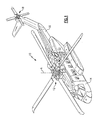
- FIG 1 schematically illustrates a rotary-wing aircraft 10 having a main rotor system 12.
- the aircraft 10 includes an airframe 14 having an extending tail 16 which mounts an anti-torque system 18.
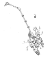
- the main rotor system 12 is driven about an axis of rotation A through a main rotor gearbox (MGB) 20 by a multi-engine powerplant system 22 - here having two engine packages ENG1, ENG2 ( Figure 2 ).
- the multi-engine powerplant system 22 generates the power available for flight operations and couples such power to the main rotor system 12 and the anti-torque system 18 through the MGB 20.
- a particular helicopter configuration is illustrated and described in the disclosed embodiment, other configurations and/or machines, such as fixed wing aircraft, high speed compound rotary-wing aircraft with supplemental translational thrust systems, turbo-props and tilt-rotor aircraft applications will also benefit herefrom.
- Each engine package ENG1, ENG2 in this non-limiting embodiment is a free power type turbo shaft engine in which engine operation involves two mechanically independent internal stages. While a particular two spool turbo shaft engine package is schematically illustrated in the disclosed non-limiting embodiment, it should be understood that the disclosure is applicable to other gas turbine engine configurations.
- Each engine package ENG1, ENG2 includes an engine case 28 that houses a high spool 30 and a low spool 40 that rotate about an engine axis of rotation X; typically in opposite directions.
- the high spool 30 includes an axial flow compressor rotor 32, a centrifugal flow compressor rotor 34 and an axial high pressure turbine 36.
- the low spool 40 includes a power turbine rotor 42 and an output shaft 44 which is coupled to the MGB 20.
- a combustor 50 is generally arranged between the centrifugal flow compressor rotor 34 and the axial high pressure turbine 36.
- the two engine packages ENG1, ENG2 are in fluid communication with a power source 60 such as an auxiliary power unit (APU), electrical air cycle machine (eACM) or other power source which provides an on-board source of air and auxiliary electrical power.
- a power source 60 such as an auxiliary power unit (APU), electrical air cycle machine (eACM) or other power source which provides an on-board source of air and auxiliary electrical power.
- air may be obtained through engine start and cross-bleed engine valves 66A, 66B, an external source port 68 or others.
- the cross-bleed engine valves 66A, 66B or the external source port 68 is selected through position of a ground/air selector valve 80.
- Cross-bleed engine starts may be provided when one engine package ENG1, ENG2 is operating and the other engine package ENG2, ENG1 is then started with bleed-air from the operating engine package ENG1, ENG2.
- the external source port 68 provides an attachment point for a bleed-air line from an external source such as
- the external start pneumatic port 68 or power source 60 provides air through an isolation valve 62 to a nozzle system 64 in the engine case structure 28.
- the isolation valve 62 selectively permits air flow between either of the two engine packages ENG1, ENG2 through selection of cross-engine start through position of the cross-bleed engine valves 66A, 66B.
- the isolation valve 62 will also shut off flow from the power source 60 or external source port 68 for the cross-bleed engine start.
- the nozzle system 64 may be located within a case section 28A of the engine case structure 28 and arranged therearound to drive the high spool 30 to light-off speed and beyond. That is, the nozzle system 64 may be arranged around axis X and directed toward the desired rotational direction of the axial flow compressor rotor 32, the centrifugal flow compressor rotor 34, the axial high pressure turbine 36 or a combination thereof to spin-up the high spool 30 ( Figure 4 ). It should be understood that the nozzle system 64 may include a multiple of nozzles 66A, 66B arranged completely around the engine case section 28A or arranged around only a portion thereof. In one non-limiting embodiment, the nozzle system 64 may provide 40 psi (276 kPa) starter air at Ipps (0.45 kg/s).
- An accessory system 70 which includes a multiple of accessory components 72 such as, but not limited to, an engine main oil pump, a fuel control unit, a generator, a primary ignition system, a gas producer generator, an oil boost pump, an engine overspeed governor, tachometer generator, and others such that all accessory components 72 are driven by the low spool 40 so as to eliminate load on the high spool 30 ( Figure 5 ).
- An accessory gearbox 76 may be located on the engine housing 28 in a radial direction from axis X such that the accessory gearbox 76 is driven by the low spool 40 through a shaft 74.
- the accessory components 72 are driven by an accessory gearbox 76' mounted along axis X downstream of the power turbine rotor 42 such that the accessory gearbox 76' is driven directly by the output shaft 44 ( Figure 6 ).
- Fuel at start may be bootstrapped by an electric start pump 90 ( Figure 5 ) driven by the power source 60 until the low spool 40 supports the main fuel pump. Electrical current may be supplied to the ignition exciter through an electrical source such as an alternator driven directly by the power source 60. It should be understood that other fuel supply bootstrap and ignition arrangements such as a battery which provides on-board electrical power may be alternatively or additionally provided until the low spool 40 spins-up to a speed which supports the main fuel pump and the primary ignition system.
- the power source 60 supplies air to the nozzle system 64 of engine package ENG1 to drive the high spool 30 to lightoff speed and beyond. Concurrent therewith, fuel is bootstrapped by the start pump 90 driven by the power source 60 until the low spool 40 supports the boost pump and main fuel pump. Once light-off occurs for engine package ENG1, the isolation valve 62 is positioned so that engine package ENG2 is spun-up through cross-bleed from ENG1. Alternately, the isolation valve 62 is positioned to directly supplies air to the nozzle system 64 of engine package ENG2 to drive the high spool 30 of engine package ENG2 to light-off speed.
Landscapes
- Engineering & Computer Science (AREA)
- Mechanical Engineering (AREA)
- Chemical & Material Sciences (AREA)
- Combustion & Propulsion (AREA)
- General Engineering & Computer Science (AREA)
- Aviation & Aerospace Engineering (AREA)
- Control Of Turbines (AREA)
- Supercharger (AREA)
- Connection Of Motors, Electrical Generators, Mechanical Devices, And The Like (AREA)
Abstract
Description
- The present disclosure relates to a gas turbine engine, and more particularly to a start system therefor.
- Aircraft powered by gas turbine engines such as a rotorcraft often utilizes pneumatic or electric starter motors which operate through an accessory gearbox. A rotor accessory gearbox also mounted on the engine housing is driven by a shaft from the power output shaft which generally operates at a constant rpm. In an aircraft such as a rotorcraft, accessories typically connected to the rotor accessory gearbox include an oil boost pump, an engine overspeed governor and a tachometer generator. A rotor accessory gearbox is typically mounted on the engine housing and is connected to the stage through a shaft and gear train. In an aircraft such as a rotorcraft, accessories typically connected to the rotor accessory gearbox include an engine main oil pump, fuel control unit, starter-generator, and gas producer generator.
- As the starter motor drives the accessory gearbox, the accessory gearbox motors the gas turbine engine. The accessory gearbox also turns the engine alternator so that electrical current is supplied to the engine electrical system. Ignition will continue until either the engine ignition switch is moved to off or starter motor dropout occurs.
- Although effective, this arrangement may utilize a relatively significant amount of packaging space and be disadvantageous from a weight perspective due in part to the multiple starter motors and accessory gearbox components.
- A start system for an engine package with a high spool according to an exemplary aspect of the present disclosure includes a power source which generates air. A nozzle system is in fluid communication with the power source, the nozzle system being operable to direct air toward the high spool to spin-up the high spool.
- A gas turbine engine powerplant system according to an exemplary aspect of the present disclosure includes an engine package with a high spool and a low spool; a power source which generates air and a nozzle system in fluid communication with the power source, the nozzle system being operable to direct air toward said high spool to spin-up said high spool.
- A method of starting a gas turbine engine powerplant system with a high spool and a low spool according to an exemplary aspect of the present disclosure includes supplying air to a nozzle system of an engine package to spin-up the high spool to light off speed and driving an accessory system with only the low spool once light off is achieved.
- Various features will become apparent to those skilled in the art from the following detailed description of the disclosed non-limiting embodiment. The drawings that accompany the detailed description can be briefly described as follows:
-
Figure 1 is a general perspective view of an exemplary rotary wing aircraft embodiment for use with the present disclosure; -
Figure 2 is a schematic view of a drive system of a rotary-wing aircraft; -
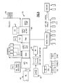
Figure 3 is a schematic block diagram view of one non-limiting embodiment of a start system; -
Figure 4 is a schematic view of nozzle system located within a compressor case section to drive the high spool to light-off; -
Figure 5 is a schematic block diagram view of an accessory system; and -
Figure 6 is a schematic block diagram view of another non-limiting embodiment of a start system. -
Figure 1 schematically illustrates a rotary-wing aircraft 10 having amain rotor system 12. The aircraft 10 includes anairframe 14 having an extendingtail 16 which mounts ananti-torque system 18. Themain rotor system 12 is driven about an axis of rotation A through a main rotor gearbox (MGB) 20 by a multi-engine powerplant system 22 - here having two engine packages ENG1, ENG2 (Figure 2 ). Themulti-engine powerplant system 22 generates the power available for flight operations and couples such power to themain rotor system 12 and theanti-torque system 18 through the MGB 20. Although a particular helicopter configuration is illustrated and described in the disclosed embodiment, other configurations and/or machines, such as fixed wing aircraft, high speed compound rotary-wing aircraft with supplemental translational thrust systems, turbo-props and tilt-rotor aircraft applications will also benefit herefrom. - Referring to
Figure 3 , astart system 26 for themulti-engine powerplant system 22 is illustrated as a schematic block diagram. Each engine package ENG1, ENG2 in this non-limiting embodiment is a free power type turbo shaft engine in which engine operation involves two mechanically independent internal stages. While a particular two spool turbo shaft engine package is schematically illustrated in the disclosed non-limiting embodiment, it should be understood that the disclosure is applicable to other gas turbine engine configurations. - Each engine package ENG1, ENG2 includes an
engine case 28 that houses ahigh spool 30 and alow spool 40 that rotate about an engine axis of rotation X; typically in opposite directions. In one non-limiting engine embodiment, thehigh spool 30 includes an axialflow compressor rotor 32, a centrifugalflow compressor rotor 34 and an axialhigh pressure turbine 36. Thelow spool 40 includes apower turbine rotor 42 and anoutput shaft 44 which is coupled to the MGB 20. Acombustor 50 is generally arranged between the centrifugalflow compressor rotor 34 and the axialhigh pressure turbine 36. - The two engine packages ENG1, ENG2 are in fluid communication with a
power source 60 such as an auxiliary power unit (APU), electrical air cycle machine (eACM) or other power source which provides an on-board source of air and auxiliary electrical power. Alternatively, or in addition thereto, air may be obtained through engine start and cross-bleedengine valves external source port 68 or others. Thecross-bleed engine valves external source port 68 is selected through position of a ground/air selector valve 80. Cross-bleed engine starts may be provided when one engine package ENG1, ENG2 is operating and the other engine package ENG2, ENG1 is then started with bleed-air from the operating engine package ENG1, ENG2. Theexternal source port 68 provides an attachment point for a bleed-air line from an external source such as a pneumatic cart or another aircraft. Either external startpneumatic port 68 orpower source 60 can be selected with the ground/air selector valve 80. - The external start
pneumatic port 68 orpower source 60 provides air through anisolation valve 62 to anozzle system 64 in theengine case structure 28. Theisolation valve 62 selectively permits air flow between either of the two engine packages ENG1, ENG2 through selection of cross-engine start through position of thecross-bleed engine valves isolation valve 62 will also shut off flow from thepower source 60 orexternal source port 68 for the cross-bleed engine start. - The
nozzle system 64 may be located within acase section 28A of theengine case structure 28 and arranged therearound to drive thehigh spool 30 to light-off speed and beyond. That is, thenozzle system 64 may be arranged around axis X and directed toward the desired rotational direction of the axialflow compressor rotor 32, the centrifugalflow compressor rotor 34, the axialhigh pressure turbine 36 or a combination thereof to spin-up the high spool 30 (Figure 4 ). It should be understood that thenozzle system 64 may include a multiple ofnozzles engine case section 28A or arranged around only a portion thereof. In one non-limiting embodiment, thenozzle system 64 may provide 40 psi (276 kPa) starter air at Ipps (0.45 kg/s). - An
accessory system 70 which includes a multiple ofaccessory components 72 such as, but not limited to, an engine main oil pump, a fuel control unit, a generator, a primary ignition system, a gas producer generator, an oil boost pump, an engine overspeed governor, tachometer generator, and others such that allaccessory components 72 are driven by thelow spool 40 so as to eliminate load on the high spool 30 (Figure 5 ). Anaccessory gearbox 76 may be located on theengine housing 28 in a radial direction from axis X such that theaccessory gearbox 76 is driven by thelow spool 40 through ashaft 74. Alternatively, theaccessory components 72 are driven by an accessory gearbox 76' mounted along axis X downstream of thepower turbine rotor 42 such that the accessory gearbox 76' is driven directly by the output shaft 44 (Figure 6 ). - Fuel at start may be bootstrapped by an electric start pump 90 (
Figure 5 ) driven by thepower source 60 until thelow spool 40 supports the main fuel pump. Electrical current may be supplied to the ignition exciter through an electrical source such as an alternator driven directly by thepower source 60. It should be understood that other fuel supply bootstrap and ignition arrangements such as a battery which provides on-board electrical power may be alternatively or additionally provided until thelow spool 40 spins-up to a speed which supports the main fuel pump and the primary ignition system. - In operation, the
power source 60 supplies air to thenozzle system 64 of engine package ENG1 to drive thehigh spool 30 to lightoff speed and beyond. Concurrent therewith, fuel is bootstrapped by thestart pump 90 driven by thepower source 60 until thelow spool 40 supports the boost pump and main fuel pump. Once light-off occurs for engine package ENG1, theisolation valve 62 is positioned so that engine package ENG2 is spun-up through cross-bleed from ENG1. Alternately, theisolation valve 62 is positioned to directly supplies air to thenozzle system 64 of engine package ENG2 to drive thehigh spool 30 of engine package ENG2 to light-off speed. - Such an arrangement eliminates need for air or electric starter for each engine package and reduces the size and weight of
high spool 30. Weight savings of 20% have been achieved over current systems as well as concomitant cost and reliability improvements. - Although particular step sequences are shown, described, and claimed, it should be understood that steps may be performed in any order, separated or combined unless otherwise indicated and will still benefit from the present disclosure.
- The foregoing description is exemplary rather than defined by the limitations within. Various non-limiting embodiments are disclosed herein, however, one of ordinary skill in the art would recognize that various modifications and variations in light of the above teachings will fall within the scope of the appended claims. It is therefore to be understood that within the scope of the appended claims, the disclosure may be practiced other than as specifically described. For that reason the appended claims should be studied to determine true scope and content.
Claims (14)
- A start system (26) for an engine package with a high spool (30) comprising:a power source (60) which generates air; anda nozzle system (64) in fluid communication with said power source, said nozzle system being operable to direct air toward the high spool to spin-up the high spool.
- The system as recited in claim 1, wherein said power source (60) is an auxiliary power unit.
- The system as recited in claim 1, wherein said power source (60) is an electrical air cycle machine.
- A gas turbine engine powerplant system comprising:an engine package (END1,ENG2) with a high spool (30) and a low spool (40); anda start system as claimed in any preceding claim.
- The system as recited in claim 4, wherein said high spool (30) includes an axial flow compressor rotor (32), and said nozzle system (64) directs said air toward said axial flow compressor rotor.
- The system as recited in claim 4 or 5, wherein said high spool (30) includes a centrifugal flow compressor rotor (34), and said nozzle system (64) directs said air toward said centrifugal flow compressor rotor.
- The system as recited in claim 4, 5 or 6, wherein said high spool (30) includes an axial high pressure turbine (36), and said nozzle system (64) directs said air toward said axial high pressure turbine.
- The system as recited in claim 4, 5, 6 or 7, wherein said low spool (40) includes a power turbine rotor (42).
- The system as recited in claim 8, wherein said power turbine rotor (42) drives an output shaft (44).
- The system as recited in any of claims 4 to 9, further comprising an accessory system (70) driven by said low spool.
- The system as recited in any preceding claim, wherein said nozzle system (64) is mounted within an engine case structure (28).
- The system as recited in claim 11, wherein said nozzle system (64) is arranged at least partially around an engine axis of rotation (X).
- A method of starting a gas turbine engine powerplant system with a high spool (30) and a low spool (40) comprising:supplying air to a nozzle system (64) of an engine package to spin-up the high spool to light off speed; anddriving an accessory system (70) with only the low spool once light off is achieved.
- A method as recited in claim 13, further comprising starting a second engine package with crossbleed from the engine package after the engine package completes start.
Applications Claiming Priority (1)
| Application Number | Priority Date | Filing Date | Title |
|---|---|---|---|
| US12/491,310 US20100326085A1 (en) | 2009-06-25 | 2009-06-25 | Lightweight start system for a gas turbine engine |
Publications (3)
| Publication Number | Publication Date |
|---|---|
| EP2267288A2 true EP2267288A2 (en) | 2010-12-29 |
| EP2267288A3 EP2267288A3 (en) | 2014-05-21 |
| EP2267288B1 EP2267288B1 (en) | 2020-05-06 |
Family
ID=42555414
Family Applications (1)
| Application Number | Title | Priority Date | Filing Date |
|---|---|---|---|
| EP10251077.3A Active EP2267288B1 (en) | 2009-06-25 | 2010-06-11 | Gas turbine engine and method of starting the same |
Country Status (3)
| Country | Link |
|---|---|
| US (1) | US20100326085A1 (en) |
| EP (1) | EP2267288B1 (en) |
| JP (1) | JP2011007183A (en) |
Cited By (8)
| Publication number | Priority date | Publication date | Assignee | Title |
|---|---|---|---|---|
| WO2015040310A1 (en) * | 2013-09-19 | 2015-03-26 | Snecma | System and method for the emergency starting of an aircraft turbomachine |
| WO2015145034A1 (en) * | 2014-03-27 | 2015-10-01 | Turbomeca | Method for assisting a turboshaft engine in standby of a multi-engine helicopter and architecture of a propulsion system of a helicopter comprising at least one turboshaft engine that can be in standby |
| WO2015145036A1 (en) * | 2014-03-27 | 2015-10-01 | Turbomeca | Alternative method for re-starting a helicopter turboshaft engine on standby, and multi-engine helicopter propulsion system allowing such a method to be performed |
| EP3744636A1 (en) * | 2019-05-31 | 2020-12-02 | Pratt & Whitney Canada Corp. | Air system of multi-engine aircraft |
| US11274599B2 (en) | 2019-03-27 | 2022-03-15 | Pratt & Whitney Canada Corp. | Air system switching system to allow aero-engines to operate in standby mode |
| US11274611B2 (en) | 2019-05-31 | 2022-03-15 | Pratt & Whitney Canada Corp. | Control logic for gas turbine engine fuel economy |
| US11326525B2 (en) | 2019-10-11 | 2022-05-10 | Pratt & Whitney Canada Corp. | Aircraft bleed air systems and methods |
| US11391219B2 (en) | 2019-04-18 | 2022-07-19 | Pratt & Whitney Canada Corp. | Health monitor for air switching system |
Families Citing this family (34)
| Publication number | Priority date | Publication date | Assignee | Title |
|---|---|---|---|---|
| US20140150440A1 (en) * | 2012-12-05 | 2014-06-05 | United Technologies Corporation | Gas turbine engine with a low speed spool driven pump arrangement |
| US20150330300A1 (en) * | 2013-03-14 | 2015-11-19 | United Technologies Corporation | Two spool engine core with a starter |
| US9797309B2 (en) * | 2013-04-09 | 2017-10-24 | David J. Podrog | Hafnium turbine engine and method of operation |
| US10040577B2 (en) * | 2016-02-12 | 2018-08-07 | United Technologies Corporation | Modified start sequence of a gas turbine engine |
| US10125636B2 (en) | 2016-02-12 | 2018-11-13 | United Technologies Corporation | Bowed rotor prevention system using waste heat |
| US10539079B2 (en) | 2016-02-12 | 2020-01-21 | United Technologies Corporation | Bowed rotor start mitigation in a gas turbine engine using aircraft-derived parameters |
| US10436064B2 (en) | 2016-02-12 | 2019-10-08 | United Technologies Corporation | Bowed rotor start response damping system |
| US9664070B1 (en) | 2016-02-12 | 2017-05-30 | United Technologies Corporation | Bowed rotor prevention system |
| US10443505B2 (en) | 2016-02-12 | 2019-10-15 | United Technologies Corporation | Bowed rotor start mitigation in a gas turbine engine |
| US10508567B2 (en) | 2016-02-12 | 2019-12-17 | United Technologies Corporation | Auxiliary drive bowed rotor prevention system for a gas turbine engine through an engine accessory |
| US10125691B2 (en) | 2016-02-12 | 2018-11-13 | United Technologies Corporation | Bowed rotor start using a variable position starter valve |
| US10508601B2 (en) | 2016-02-12 | 2019-12-17 | United Technologies Corporation | Auxiliary drive bowed rotor prevention system for a gas turbine engine |
| US10443507B2 (en) | 2016-02-12 | 2019-10-15 | United Technologies Corporation | Gas turbine engine bowed rotor avoidance system |
| US10174678B2 (en) | 2016-02-12 | 2019-01-08 | United Technologies Corporation | Bowed rotor start using direct temperature measurement |
| US10563590B2 (en) * | 2016-05-19 | 2020-02-18 | Hamilton Sundstrand Corporation | System and method of gas turbine engine shaft cooling |
| US10358936B2 (en) | 2016-07-05 | 2019-07-23 | United Technologies Corporation | Bowed rotor sensor system |
| US10618666B2 (en) | 2016-07-21 | 2020-04-14 | United Technologies Corporation | Pre-start motoring synchronization for multiple engines |
| EP3273016B1 (en) | 2016-07-21 | 2020-04-01 | United Technologies Corporation | Multi-engine coordination during gas turbine engine motoring |
| US10384791B2 (en) * | 2016-07-21 | 2019-08-20 | United Technologies Corporation | Cross engine coordination during gas turbine engine motoring |
| EP3273006B1 (en) | 2016-07-21 | 2019-07-03 | United Technologies Corporation | Alternating starter use during multi-engine motoring |
| US11300199B2 (en) * | 2016-09-23 | 2022-04-12 | Textron Innovations Inc. | Non-pressurized accessory gearbox |
| US10787968B2 (en) | 2016-09-30 | 2020-09-29 | Raytheon Technologies Corporation | Gas turbine engine motoring with starter air valve manual override |
| US10823079B2 (en) | 2016-11-29 | 2020-11-03 | Raytheon Technologies Corporation | Metered orifice for motoring of a gas turbine engine |
| US10669945B2 (en) | 2017-02-06 | 2020-06-02 | Raytheon Technologies Corporation | Starter air valve system with dual electromechanical controls |
| US11156122B2 (en) | 2018-06-19 | 2021-10-26 | Raytheon Technologies Corporation | Airfoil cooling system |
| US10954857B2 (en) | 2018-06-19 | 2021-03-23 | Raytheon Technologies Corporation | Crossover cooling flow for multi-engine systems |
| US11143142B2 (en) * | 2018-08-01 | 2021-10-12 | United Technologies Corporation | Adaptive engine with boost spool |
| JP7430134B2 (en) * | 2020-12-22 | 2024-02-09 | 本田技研工業株式会社 | Aircraft propulsion system |
| US11814969B2 (en) * | 2021-07-21 | 2023-11-14 | Pratt & Whitney Canada Corp. | Gas turbine engine with low-pressure compressor bypass |
| US11859554B2 (en) * | 2021-07-29 | 2024-01-02 | Pratt & Whitney Canada Corp. | Fast engine re-start for multi-engine system and method |
| US11976598B2 (en) * | 2022-05-05 | 2024-05-07 | Rtx Corporation | Transmission and method for control of boost spool |
| US11898490B2 (en) | 2022-05-05 | 2024-02-13 | Rtx Corporation | Transmission and method for control of boost spool |
| GB202319150D0 (en) | 2023-12-14 | 2024-01-31 | Rolls Royce Plc | Fueldraulic heat management system |
| GB202319148D0 (en) * | 2023-12-14 | 2024-01-31 | Rolls Royce Plc | Gas turbine bleed air valve |
Family Cites Families (27)
| Publication number | Priority date | Publication date | Assignee | Title |
|---|---|---|---|---|
| GB716263A (en) * | 1953-02-06 | 1954-09-29 | Bristol Aeroplane Co Ltd | Improvements in or relating to gas turbine engines |
| CH313450A (en) * | 1953-06-17 | 1956-04-15 | Plessey Co Ltd | Starting device for gas turbine systems |
| US3085396A (en) * | 1959-07-03 | 1963-04-16 | Rolls Royce | Gas turbine engine with gas starter |
| US3357176A (en) * | 1965-09-22 | 1967-12-12 | Williams Res Corp | Twin spool gas turbine engine with axial and centrifugal compressors |
| US3514945A (en) * | 1968-10-04 | 1970-06-02 | Avco Corp | Gas turbine accessory power drive unit |
| US3965673A (en) * | 1973-05-19 | 1976-06-29 | Vereinigte Flugtechnische Werke-Fokker Gesellschaft Mit Beschrankter Haftung | Apparatus for starting aircraft engines and for operating auxiliary on-board power generating equipment |
| DE2538756C2 (en) * | 1975-08-30 | 1983-11-24 | BBC Aktiengesellschaft Brown, Boveri & Cie., 5401 Baden, Aargau | Method for starting up a gas turbine system with air storage |
| DE2926514A1 (en) * | 1979-06-30 | 1981-01-15 | Ibm Deutschland | ELECTRICAL MEMORY ARRANGEMENT AND METHOD FOR THEIR OPERATION |
| JPS58126436A (en) * | 1982-01-22 | 1983-07-27 | Nissan Motor Co Ltd | Starting method of gas turbine |
| JPH0621572B2 (en) * | 1984-12-14 | 1994-03-23 | 株式会社日立製作所 | Gas turbine plant starting method and gas turbine plant |
| JPH01249925A (en) * | 1988-03-31 | 1989-10-05 | Toshiba Corp | Starting system for turbocharger |
| US4979362A (en) * | 1989-05-17 | 1990-12-25 | Sundstrand Corporation | Aircraft engine starting and emergency power generating system |
| US5136837A (en) * | 1990-03-06 | 1992-08-11 | General Electric Company | Aircraft engine starter integrated boundary bleed system |
| US6438962B1 (en) * | 2000-09-11 | 2002-08-27 | Hamilton Sundstrand Corporation | System and method for starting an engine |
| US6704625B2 (en) * | 2001-02-16 | 2004-03-09 | Hamilton Sunstrand Corporation | Aircraft architecture with a reduced bleed aircraft secondary power system |
| US6498978B2 (en) * | 2001-05-18 | 2002-12-24 | General Electric Company | System and method for monitoring thermal state to normalize engine trending data |
| FR2826055B1 (en) * | 2001-06-14 | 2003-12-19 | Snecma Moteurs | VARIABLE CYCLE PROPULSION DEVICE WITH COMPRESSED AIR TAKE-OFF FOR SUPERSONIC AIRCRAFT |
| US6968701B2 (en) * | 2002-01-16 | 2005-11-29 | United Technologies Corporation | Engine integrated auxiliary power unit |
| US6644033B2 (en) * | 2002-01-17 | 2003-11-11 | The Boeing Company | Tip impingement turbine air starter for turbine engine |
| US6792760B2 (en) * | 2002-03-11 | 2004-09-21 | Alstom Technology Ltd | Method for operating a turbine |
| US6838779B1 (en) * | 2002-06-24 | 2005-01-04 | Hamilton Sundstrand Corporation | Aircraft starter generator for variable frequency (vf) electrical system |
| US7210653B2 (en) * | 2002-10-22 | 2007-05-01 | The Boeing Company | Electric-based secondary power system architectures for aircraft |
| US7117683B2 (en) * | 2004-08-25 | 2006-10-10 | Hamilton Sundstrand Corporation | Main engine electric start system |
| US7513119B2 (en) * | 2005-02-03 | 2009-04-07 | The Boeing Company | Systems and methods for starting aircraft engines |
| US7802757B2 (en) * | 2005-11-09 | 2010-09-28 | Pratt & Whitney Canada Corp. | Method and system for taxiing an aircraft |
| US20080148881A1 (en) * | 2006-12-21 | 2008-06-26 | Thomas Ory Moniz | Power take-off system and gas turbine engine assembly including same |
| JP2008056240A (en) * | 2007-10-29 | 2008-03-13 | Shimadzu Corp | Air conditioner for aircraft |
-
2009
- 2009-06-25 US US12/491,310 patent/US20100326085A1/en not_active Abandoned
-
2010
- 2010-06-11 EP EP10251077.3A patent/EP2267288B1/en active Active
- 2010-06-22 JP JP2010141141A patent/JP2011007183A/en active Pending
Non-Patent Citations (1)
| Title |
|---|
| None |
Cited By (19)
| Publication number | Priority date | Publication date | Assignee | Title |
|---|---|---|---|---|
| US9951694B2 (en) | 2013-09-19 | 2018-04-24 | Safran Aircraft Engines | System and method for emergency starting of an aircraft turbomachine |
| WO2015040310A1 (en) * | 2013-09-19 | 2015-03-26 | Snecma | System and method for the emergency starting of an aircraft turbomachine |
| RU2660725C2 (en) * | 2013-09-19 | 2018-07-09 | Сафран Эркрафт Энджинз | Aircraft gas turbine engine emergency starting system and method |
| CN106460662B (en) * | 2014-03-27 | 2018-10-02 | 赛峰直升机发动机公司 | For the method for auxiliary turbine shaft generator and the framework of helicopter propulsion system |
| US10337409B2 (en) | 2014-03-27 | 2019-07-02 | Safran Helicopter Engines | Method for assisting a turboshaft engine in standby of a multiple-engine helicopter, and architecture of a propulsion system of a helicopter comprising at least one turboshaft engine that can be in standby |
| CN106460662A (en) * | 2014-03-27 | 2017-02-22 | 赛峰直升机发动机公司 | Method for assisting a turboshaft engine in standby of a multi-engine helicopter and architecture of a propulsion system of a helicopter comprising at least one turboshaft engine that can be in standby |
| FR3019220A1 (en) * | 2014-03-27 | 2015-10-02 | Turbomeca | METHOD FOR ALTERNATE RESTART OF A HELICOPTER SLEEPING TURBOMOTE AND MULTI-ENGINE ARCHITECTURE FOR IMPLEMENTING SUCH A METHOD |
| WO2015145036A1 (en) * | 2014-03-27 | 2015-10-01 | Turbomeca | Alternative method for re-starting a helicopter turboshaft engine on standby, and multi-engine helicopter propulsion system allowing such a method to be performed |
| WO2015145034A1 (en) * | 2014-03-27 | 2015-10-01 | Turbomeca | Method for assisting a turboshaft engine in standby of a multi-engine helicopter and architecture of a propulsion system of a helicopter comprising at least one turboshaft engine that can be in standby |
| RU2689266C2 (en) * | 2014-03-27 | 2019-05-24 | Сафран Хеликоптер Энджинз | Method of amplifying gas turbine engine in standby mode of multi-engine helicopter and structure of helicopter power plant comprising at least one gas turbine engine which can be in standby mode |
| FR3019224A1 (en) * | 2014-03-27 | 2015-10-02 | Turbomeca | METHOD FOR ASSISTING A MULTI-ENGINE HELICOPTER SLEEPING TURBOMOTEUR AND ARCHITECTURE OF A PROPELLANT HELICOPTER SYSTEM COMPRISING AT LEAST ONE TURBOMOTEUR WHICH CAN BE ON SLEEP |
| US11274599B2 (en) | 2019-03-27 | 2022-03-15 | Pratt & Whitney Canada Corp. | Air system switching system to allow aero-engines to operate in standby mode |
| US11732643B2 (en) | 2019-03-27 | 2023-08-22 | Pratt & Whitney Canada Corp | Air system switching system to allow aero-engines to operate in standby mode |
| US11391219B2 (en) | 2019-04-18 | 2022-07-19 | Pratt & Whitney Canada Corp. | Health monitor for air switching system |
| EP3744636A1 (en) * | 2019-05-31 | 2020-12-02 | Pratt & Whitney Canada Corp. | Air system of multi-engine aircraft |
| US11274611B2 (en) | 2019-05-31 | 2022-03-15 | Pratt & Whitney Canada Corp. | Control logic for gas turbine engine fuel economy |
| US11725595B2 (en) | 2019-05-31 | 2023-08-15 | Pratt & Whitney Canada Corp. | Control logic for gas turbine engine fuel economy |
| US11859563B2 (en) | 2019-05-31 | 2024-01-02 | Pratt & Whitney Canada Corp. | Air system of multi-engine aircraft |
| US11326525B2 (en) | 2019-10-11 | 2022-05-10 | Pratt & Whitney Canada Corp. | Aircraft bleed air systems and methods |
Also Published As
| Publication number | Publication date |
|---|---|
| US20100326085A1 (en) | 2010-12-30 |
| EP2267288B1 (en) | 2020-05-06 |
| EP2267288A3 (en) | 2014-05-21 |
| JP2011007183A (en) | 2011-01-13 |
Similar Documents
| Publication | Publication Date | Title |
|---|---|---|
| EP2267288B1 (en) | Gas turbine engine and method of starting the same | |
| US9200592B2 (en) | Mechanism for turbine engine start from low spool | |
| EP3957843B1 (en) | Hybrid through-flow gas turbine engine with electric motor and electric generator | |
| US7882691B2 (en) | High to low pressure spool summing gearbox for accessory power extraction and electric start | |
| US11248532B2 (en) | Hybrid electric dual spool power extraction gearbox | |
| US7973422B2 (en) | Device for producing electrical power in a two-spool gas turbine engine | |
| EP3910174B1 (en) | Reverse-flow gas turbine engine with electric motor | |
| CN112664320A (en) | Gas turbine engine supercharger configuration and method of operation | |
| US20180149091A1 (en) | Power extraction system and method for a gas turbine engine of a vehicle | |
| US9511872B2 (en) | Power plant, an application of such a power plant and a method of operating such a power plant | |
| US20110154805A1 (en) | Power augmentation system for an engine powered air vehicle | |
| US11408340B2 (en) | Twin-engine system with electric drive | |
| US9973058B2 (en) | Propeller in-hub power generation and control | |
| US11846198B2 (en) | Turbomachine having a free turbine comprising electric machines assisting a gas generator and a free turbine | |
| EP2407660A2 (en) | Auxiliary hydraulic power generation system | |
| EP4407158B1 (en) | Systems and methods of dual-spool power management | |
| US12071853B2 (en) | Free-turbine turbomachine comprising equipment driven by the free turbine | |
| US12480449B2 (en) | Propulsion system including an electric machine for starting a gas turbine engine | |
| EP4328439A1 (en) | Propulsion system including an electric machine for starting a gas turbine engine | |
| US12589878B1 (en) | Hybrid-electric aircraft propulsion system | |
| CN117605576A (en) | Propulsion system including an electric machine for starting a gas turbine engine |
Legal Events
| Date | Code | Title | Description |
|---|---|---|---|
| PUAI | Public reference made under article 153(3) epc to a published international application that has entered the european phase |
Free format text: ORIGINAL CODE: 0009012 |
|
| AK | Designated contracting states |
Kind code of ref document: A2 Designated state(s): AL AT BE BG CH CY CZ DE DK EE ES FI FR GB GR HR HU IE IS IT LI LT LU LV MC MK MT NL NO PL PT RO SE SI SK SM TR |
|
| AX | Request for extension of the european patent |
Extension state: BA ME RS |
|
| PUAL | Search report despatched |
Free format text: ORIGINAL CODE: 0009013 |
|
| AK | Designated contracting states |
Kind code of ref document: A3 Designated state(s): AL AT BE BG CH CY CZ DE DK EE ES FI FR GB GR HR HU IE IS IT LI LT LU LV MC MK MT NL NO PL PT RO SE SI SK SM TR |
|
| AX | Request for extension of the european patent |
Extension state: BA ME RS |
|
| RIC1 | Information provided on ipc code assigned before grant |
Ipc: F02C 3/13 20060101ALI20140415BHEP Ipc: F01D 1/06 20060101ALI20140415BHEP Ipc: B64C 27/14 20060101ALI20140415BHEP Ipc: F02C 7/27 20060101AFI20140415BHEP Ipc: F01D 1/16 20060101ALI20140415BHEP Ipc: F02C 3/10 20060101ALI20140415BHEP |
|
| 17P | Request for examination filed |
Effective date: 20141112 |
|
| RBV | Designated contracting states (corrected) |
Designated state(s): AL AT BE BG CH CY CZ DE DK EE ES FI FR GB GR HR HU IE IS IT LI LT LU LV MC MK MT NL NO PL PT RO SE SI SK SM TR |
|
| STAA | Information on the status of an ep patent application or granted ep patent |
Free format text: STATUS: EXAMINATION IS IN PROGRESS |
|
| 17Q | First examination report despatched |
Effective date: 20171006 |
|
| GRAP | Despatch of communication of intention to grant a patent |
Free format text: ORIGINAL CODE: EPIDOSNIGR1 |
|
| STAA | Information on the status of an ep patent application or granted ep patent |
Free format text: STATUS: GRANT OF PATENT IS INTENDED |
|
| INTG | Intention to grant announced |
Effective date: 20200124 |
|
| GRAS | Grant fee paid |
Free format text: ORIGINAL CODE: EPIDOSNIGR3 |
|
| GRAA | (expected) grant |
Free format text: ORIGINAL CODE: 0009210 |
|
| STAA | Information on the status of an ep patent application or granted ep patent |
Free format text: STATUS: THE PATENT HAS BEEN GRANTED |
|
| RAP1 | Party data changed (applicant data changed or rights of an application transferred) |
Owner name: HAMILTON SUNDSTRAND CORPORATION |
|
| AK | Designated contracting states |
Kind code of ref document: B1 Designated state(s): AL AT BE BG CH CY CZ DE DK EE ES FI FR GB GR HR HU IE IS IT LI LT LU LV MC MK MT NL NO PL PT RO SE SI SK SM TR |
|
| REG | Reference to a national code |
Ref country code: GB Ref legal event code: FG4D |
|
| REG | Reference to a national code |
Ref country code: CH Ref legal event code: EP Ref country code: AT Ref legal event code: REF Ref document number: 1267105 Country of ref document: AT Kind code of ref document: T Effective date: 20200515 |
|
| REG | Reference to a national code |
Ref country code: DE Ref legal event code: R096 Ref document number: 602010064206 Country of ref document: DE |
|
| REG | Reference to a national code |
Ref country code: IE Ref legal event code: FG4D |
|
| PGFP | Annual fee paid to national office [announced via postgrant information from national office to epo] |
Ref country code: FR Payment date: 20200623 Year of fee payment: 11 Ref country code: DE Payment date: 20200519 Year of fee payment: 11 |
|
| PGFP | Annual fee paid to national office [announced via postgrant information from national office to epo] |
Ref country code: GB Payment date: 20200624 Year of fee payment: 11 |
|
| REG | Reference to a national code |
Ref country code: LT Ref legal event code: MG4D |
|
| REG | Reference to a national code |
Ref country code: NL Ref legal event code: MP Effective date: 20200506 |
|
| PG25 | Lapsed in a contracting state [announced via postgrant information from national office to epo] |
Ref country code: SE Free format text: LAPSE BECAUSE OF FAILURE TO SUBMIT A TRANSLATION OF THE DESCRIPTION OR TO PAY THE FEE WITHIN THE PRESCRIBED TIME-LIMIT Effective date: 20200506 Ref country code: LT Free format text: LAPSE BECAUSE OF FAILURE TO SUBMIT A TRANSLATION OF THE DESCRIPTION OR TO PAY THE FEE WITHIN THE PRESCRIBED TIME-LIMIT Effective date: 20200506 Ref country code: PT Free format text: LAPSE BECAUSE OF FAILURE TO SUBMIT A TRANSLATION OF THE DESCRIPTION OR TO PAY THE FEE WITHIN THE PRESCRIBED TIME-LIMIT Effective date: 20200907 Ref country code: IS Free format text: LAPSE BECAUSE OF FAILURE TO SUBMIT A TRANSLATION OF THE DESCRIPTION OR TO PAY THE FEE WITHIN THE PRESCRIBED TIME-LIMIT Effective date: 20200906 Ref country code: GR Free format text: LAPSE BECAUSE OF FAILURE TO SUBMIT A TRANSLATION OF THE DESCRIPTION OR TO PAY THE FEE WITHIN THE PRESCRIBED TIME-LIMIT Effective date: 20200807 Ref country code: NO Free format text: LAPSE BECAUSE OF FAILURE TO SUBMIT A TRANSLATION OF THE DESCRIPTION OR TO PAY THE FEE WITHIN THE PRESCRIBED TIME-LIMIT Effective date: 20200806 Ref country code: FI Free format text: LAPSE BECAUSE OF FAILURE TO SUBMIT A TRANSLATION OF THE DESCRIPTION OR TO PAY THE FEE WITHIN THE PRESCRIBED TIME-LIMIT Effective date: 20200506 |
|
| PG25 | Lapsed in a contracting state [announced via postgrant information from national office to epo] |
Ref country code: LV Free format text: LAPSE BECAUSE OF FAILURE TO SUBMIT A TRANSLATION OF THE DESCRIPTION OR TO PAY THE FEE WITHIN THE PRESCRIBED TIME-LIMIT Effective date: 20200506 Ref country code: HR Free format text: LAPSE BECAUSE OF FAILURE TO SUBMIT A TRANSLATION OF THE DESCRIPTION OR TO PAY THE FEE WITHIN THE PRESCRIBED TIME-LIMIT Effective date: 20200506 Ref country code: BG Free format text: LAPSE BECAUSE OF FAILURE TO SUBMIT A TRANSLATION OF THE DESCRIPTION OR TO PAY THE FEE WITHIN THE PRESCRIBED TIME-LIMIT Effective date: 20200806 |
|
| REG | Reference to a national code |
Ref country code: AT Ref legal event code: MK05 Ref document number: 1267105 Country of ref document: AT Kind code of ref document: T Effective date: 20200506 |
|
| PG25 | Lapsed in a contracting state [announced via postgrant information from national office to epo] |
Ref country code: AL Free format text: LAPSE BECAUSE OF FAILURE TO SUBMIT A TRANSLATION OF THE DESCRIPTION OR TO PAY THE FEE WITHIN THE PRESCRIBED TIME-LIMIT Effective date: 20200506 Ref country code: NL Free format text: LAPSE BECAUSE OF FAILURE TO SUBMIT A TRANSLATION OF THE DESCRIPTION OR TO PAY THE FEE WITHIN THE PRESCRIBED TIME-LIMIT Effective date: 20200506 |
|
| PG25 | Lapsed in a contracting state [announced via postgrant information from national office to epo] |
Ref country code: RO Free format text: LAPSE BECAUSE OF FAILURE TO SUBMIT A TRANSLATION OF THE DESCRIPTION OR TO PAY THE FEE WITHIN THE PRESCRIBED TIME-LIMIT Effective date: 20200506 Ref country code: CZ Free format text: LAPSE BECAUSE OF FAILURE TO SUBMIT A TRANSLATION OF THE DESCRIPTION OR TO PAY THE FEE WITHIN THE PRESCRIBED TIME-LIMIT Effective date: 20200506 Ref country code: IT Free format text: LAPSE BECAUSE OF FAILURE TO SUBMIT A TRANSLATION OF THE DESCRIPTION OR TO PAY THE FEE WITHIN THE PRESCRIBED TIME-LIMIT Effective date: 20200506 Ref country code: ES Free format text: LAPSE BECAUSE OF FAILURE TO SUBMIT A TRANSLATION OF THE DESCRIPTION OR TO PAY THE FEE WITHIN THE PRESCRIBED TIME-LIMIT Effective date: 20200506 Ref country code: AT Free format text: LAPSE BECAUSE OF FAILURE TO SUBMIT A TRANSLATION OF THE DESCRIPTION OR TO PAY THE FEE WITHIN THE PRESCRIBED TIME-LIMIT Effective date: 20200506 Ref country code: DK Free format text: LAPSE BECAUSE OF FAILURE TO SUBMIT A TRANSLATION OF THE DESCRIPTION OR TO PAY THE FEE WITHIN THE PRESCRIBED TIME-LIMIT Effective date: 20200506 Ref country code: EE Free format text: LAPSE BECAUSE OF FAILURE TO SUBMIT A TRANSLATION OF THE DESCRIPTION OR TO PAY THE FEE WITHIN THE PRESCRIBED TIME-LIMIT Effective date: 20200506 Ref country code: SM Free format text: LAPSE BECAUSE OF FAILURE TO SUBMIT A TRANSLATION OF THE DESCRIPTION OR TO PAY THE FEE WITHIN THE PRESCRIBED TIME-LIMIT Effective date: 20200506 |
|
| REG | Reference to a national code |
Ref country code: CH Ref legal event code: PL |
|
| REG | Reference to a national code |
Ref country code: DE Ref legal event code: R097 Ref document number: 602010064206 Country of ref document: DE |
|
| PG25 | Lapsed in a contracting state [announced via postgrant information from national office to epo] |
Ref country code: SK Free format text: LAPSE BECAUSE OF FAILURE TO SUBMIT A TRANSLATION OF THE DESCRIPTION OR TO PAY THE FEE WITHIN THE PRESCRIBED TIME-LIMIT Effective date: 20200506 Ref country code: MC Free format text: LAPSE BECAUSE OF FAILURE TO SUBMIT A TRANSLATION OF THE DESCRIPTION OR TO PAY THE FEE WITHIN THE PRESCRIBED TIME-LIMIT Effective date: 20200506 Ref country code: PL Free format text: LAPSE BECAUSE OF FAILURE TO SUBMIT A TRANSLATION OF THE DESCRIPTION OR TO PAY THE FEE WITHIN THE PRESCRIBED TIME-LIMIT Effective date: 20200506 |
|
| PLBE | No opposition filed within time limit |
Free format text: ORIGINAL CODE: 0009261 |
|
| STAA | Information on the status of an ep patent application or granted ep patent |
Free format text: STATUS: NO OPPOSITION FILED WITHIN TIME LIMIT |
|
| PG25 | Lapsed in a contracting state [announced via postgrant information from national office to epo] |
Ref country code: LU Free format text: LAPSE BECAUSE OF NON-PAYMENT OF DUE FEES Effective date: 20200611 |
|
| 26N | No opposition filed |
Effective date: 20210209 |
|
| REG | Reference to a national code |
Ref country code: BE Ref legal event code: MM Effective date: 20200630 |
|
| PG25 | Lapsed in a contracting state [announced via postgrant information from national office to epo] |
Ref country code: CH Free format text: LAPSE BECAUSE OF NON-PAYMENT OF DUE FEES Effective date: 20200630 Ref country code: LI Free format text: LAPSE BECAUSE OF NON-PAYMENT OF DUE FEES Effective date: 20200630 Ref country code: IE Free format text: LAPSE BECAUSE OF NON-PAYMENT OF DUE FEES Effective date: 20200611 |
|
| PG25 | Lapsed in a contracting state [announced via postgrant information from national office to epo] |
Ref country code: BE Free format text: LAPSE BECAUSE OF NON-PAYMENT OF DUE FEES Effective date: 20200630 Ref country code: SI Free format text: LAPSE BECAUSE OF FAILURE TO SUBMIT A TRANSLATION OF THE DESCRIPTION OR TO PAY THE FEE WITHIN THE PRESCRIBED TIME-LIMIT Effective date: 20200506 |
|
| REG | Reference to a national code |
Ref country code: DE Ref legal event code: R119 Ref document number: 602010064206 Country of ref document: DE |
|
| GBPC | Gb: european patent ceased through non-payment of renewal fee |
Effective date: 20210611 |
|
| PG25 | Lapsed in a contracting state [announced via postgrant information from national office to epo] |
Ref country code: GB Free format text: LAPSE BECAUSE OF NON-PAYMENT OF DUE FEES Effective date: 20210611 Ref country code: DE Free format text: LAPSE BECAUSE OF NON-PAYMENT OF DUE FEES Effective date: 20220101 |
|
| PG25 | Lapsed in a contracting state [announced via postgrant information from national office to epo] |
Ref country code: TR Free format text: LAPSE BECAUSE OF FAILURE TO SUBMIT A TRANSLATION OF THE DESCRIPTION OR TO PAY THE FEE WITHIN THE PRESCRIBED TIME-LIMIT Effective date: 20200506 Ref country code: MT Free format text: LAPSE BECAUSE OF FAILURE TO SUBMIT A TRANSLATION OF THE DESCRIPTION OR TO PAY THE FEE WITHIN THE PRESCRIBED TIME-LIMIT Effective date: 20200506 Ref country code: FR Free format text: LAPSE BECAUSE OF NON-PAYMENT OF DUE FEES Effective date: 20210630 Ref country code: CY Free format text: LAPSE BECAUSE OF FAILURE TO SUBMIT A TRANSLATION OF THE DESCRIPTION OR TO PAY THE FEE WITHIN THE PRESCRIBED TIME-LIMIT Effective date: 20200506 |
|
| PG25 | Lapsed in a contracting state [announced via postgrant information from national office to epo] |
Ref country code: MK Free format text: LAPSE BECAUSE OF FAILURE TO SUBMIT A TRANSLATION OF THE DESCRIPTION OR TO PAY THE FEE WITHIN THE PRESCRIBED TIME-LIMIT Effective date: 20200506 |