EP2267277A2 - Annulus filler and method of mounting the annulus filler to a rotor disc of a gas turbine engine - Google Patents
Annulus filler and method of mounting the annulus filler to a rotor disc of a gas turbine engine Download PDFInfo
- Publication number
- EP2267277A2 EP2267277A2 EP10165254A EP10165254A EP2267277A2 EP 2267277 A2 EP2267277 A2 EP 2267277A2 EP 10165254 A EP10165254 A EP 10165254A EP 10165254 A EP10165254 A EP 10165254A EP 2267277 A2 EP2267277 A2 EP 2267277A2
- Authority
- EP
- European Patent Office
- Prior art keywords
- rotor disc
- annulus filler
- blades
- mounting
- annulus
- Prior art date
- Legal status (The legal status is an assumption and is not a legal conclusion. Google has not performed a legal analysis and makes no representation as to the accuracy of the status listed.)
- Withdrawn
Links
- 239000000945 filler Substances 0.000 title claims abstract description 98
- 238000000034 method Methods 0.000 title claims abstract description 20
- 238000009434 installation Methods 0.000 claims abstract description 23
- 230000014759 maintenance of location Effects 0.000 description 12
- 230000015572 biosynthetic process Effects 0.000 description 7
- 238000005755 formation reaction Methods 0.000 description 7
- 238000007789 sealing Methods 0.000 description 6
- 239000000463 material Substances 0.000 description 5
- 230000000295 complement effect Effects 0.000 description 3
- 238000000748 compression moulding Methods 0.000 description 3
- 229910052751 metal Inorganic materials 0.000 description 3
- 239000002184 metal Substances 0.000 description 3
- 239000004033 plastic Substances 0.000 description 3
- 229920003023 plastic Polymers 0.000 description 3
- 229910000838 Al alloy Inorganic materials 0.000 description 2
- 229910000861 Mg alloy Inorganic materials 0.000 description 2
- 229910001069 Ti alloy Inorganic materials 0.000 description 2
- RTAQQCXQSZGOHL-UHFFFAOYSA-N Titanium Chemical compound [Ti] RTAQQCXQSZGOHL-UHFFFAOYSA-N 0.000 description 2
- 239000004411 aluminium Substances 0.000 description 2
- XAGFODPZIPBFFR-UHFFFAOYSA-N aluminium Chemical compound [Al] XAGFODPZIPBFFR-UHFFFAOYSA-N 0.000 description 2
- 239000007924 injection Substances 0.000 description 2
- 238000001746 injection moulding Methods 0.000 description 2
- 239000007769 metal material Substances 0.000 description 2
- 239000010936 titanium Substances 0.000 description 2
- 239000004593 Epoxy Substances 0.000 description 1
- 239000004962 Polyamide-imide Substances 0.000 description 1
- 239000004963 Torlon Substances 0.000 description 1
- 230000004323 axial length Effects 0.000 description 1
- 239000002131 composite material Substances 0.000 description 1
- 238000010276 construction Methods 0.000 description 1
- 239000000835 fiber Substances 0.000 description 1
- 239000003365 glass fiber Substances 0.000 description 1
- 230000005484 gravity Effects 0.000 description 1
- 238000002347 injection Methods 0.000 description 1
- 238000011900 installation process Methods 0.000 description 1
- 239000003562 lightweight material Substances 0.000 description 1
- 238000012986 modification Methods 0.000 description 1
- 230000004048 modification Effects 0.000 description 1
- 229920002312 polyamide-imide Polymers 0.000 description 1
- 229920000642 polymer Polymers 0.000 description 1
- 230000003014 reinforcing effect Effects 0.000 description 1
- 229920001169 thermoplastic Polymers 0.000 description 1
- 239000004416 thermosoftening plastic Substances 0.000 description 1
Images

Classifications
-
- F—MECHANICAL ENGINEERING; LIGHTING; HEATING; WEAPONS; BLASTING
- F01—MACHINES OR ENGINES IN GENERAL; ENGINE PLANTS IN GENERAL; STEAM ENGINES
- F01D—NON-POSITIVE DISPLACEMENT MACHINES OR ENGINES, e.g. STEAM TURBINES
- F01D5/00—Blades; Blade-carrying members; Heating, heat-insulating, cooling or antivibration means on the blades or the members
- F01D5/12—Blades
- F01D5/22—Blade-to-blade connections, e.g. for damping vibrations
-
- F—MECHANICAL ENGINEERING; LIGHTING; HEATING; WEAPONS; BLASTING
- F01—MACHINES OR ENGINES IN GENERAL; ENGINE PLANTS IN GENERAL; STEAM ENGINES
- F01D—NON-POSITIVE DISPLACEMENT MACHINES OR ENGINES, e.g. STEAM TURBINES
- F01D11/00—Preventing or minimising internal leakage of working-fluid, e.g. between stages
- F01D11/005—Sealing means between non relatively rotating elements
- F01D11/006—Sealing the gap between rotor blades or blades and rotor
- F01D11/008—Sealing the gap between rotor blades or blades and rotor by spacer elements between the blades, e.g. independent interblade platforms
-
- F—MECHANICAL ENGINEERING; LIGHTING; HEATING; WEAPONS; BLASTING
- F05—INDEXING SCHEMES RELATING TO ENGINES OR PUMPS IN VARIOUS SUBCLASSES OF CLASSES F01-F04
- F05D—INDEXING SCHEME FOR ASPECTS RELATING TO NON-POSITIVE-DISPLACEMENT MACHINES OR ENGINES, GAS-TURBINES OR JET-PROPULSION PLANTS
- F05D2220/00—Application
- F05D2220/30—Application in turbines
- F05D2220/36—Application in turbines specially adapted for the fan of turbofan engines
-
- F—MECHANICAL ENGINEERING; LIGHTING; HEATING; WEAPONS; BLASTING
- F05—INDEXING SCHEMES RELATING TO ENGINES OR PUMPS IN VARIOUS SUBCLASSES OF CLASSES F01-F04
- F05D—INDEXING SCHEME FOR ASPECTS RELATING TO NON-POSITIVE-DISPLACEMENT MACHINES OR ENGINES, GAS-TURBINES OR JET-PROPULSION PLANTS
- F05D2230/00—Manufacture
- F05D2230/60—Assembly methods
-
- Y—GENERAL TAGGING OF NEW TECHNOLOGICAL DEVELOPMENTS; GENERAL TAGGING OF CROSS-SECTIONAL TECHNOLOGIES SPANNING OVER SEVERAL SECTIONS OF THE IPC; TECHNICAL SUBJECTS COVERED BY FORMER USPC CROSS-REFERENCE ART COLLECTIONS [XRACs] AND DIGESTS
- Y10—TECHNICAL SUBJECTS COVERED BY FORMER USPC
- Y10T—TECHNICAL SUBJECTS COVERED BY FORMER US CLASSIFICATION
- Y10T29/00—Metal working
- Y10T29/49—Method of mechanical manufacture
- Y10T29/49316—Impeller making
- Y10T29/4932—Turbomachine making
- Y10T29/49321—Assembling individual fluid flow interacting members, e.g., blades, vanes, buckets, on rotary support member
Definitions
- the present invention relates to annulus fillers for bridging gaps between adjacent blades of a gas turbine engine stage.
- each compressor rotor stage of a gas turbine engine comprises a plurality of radially extending blades mounted on a rotor disc.
- the blades are mounted on the disc by inserting a root portion of the blade in a complementary retention groove in the outer face of the disc periphery.
- annulus fillers are used to bridge the spaces between adjacent blades.
- seals between the annulus fillers and the adjacent fan blades are also provided by resilient strips bonded to the annulus fillers adjacent the fan blades.
- Annulus fillers of this type are commonly used in the fan stage of gas turbine engines.
- the fillers may be manufactured from relatively lightweight materials and, in the event of damage, may be replaced independently of the blades.
- annulus fillers with features for removably attaching them to the rotor disc.
- annulus fillers with axially spaced hook members, the hook members sliding into engagement with respective parts of the rotor disc.
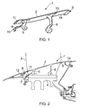
- Figure 1 shows an example of such an annulus filler viewed from the side
- Figure 2 shows the annulus filler fitted to the rotor disc as viewed in transverse cross-section.
- the upper surface or lid 2 of the annulus filler 1 bridges the gap between two adjacent fan blades 3 (one of which is shown in outline in Figure 2 ) and defines the inner wall of the flow annulus of a fan stage.
- the annulus filler 1 is mounted on a fan disc 4 by two hook members 5, 6 respectively towards the forward and rearward ends of the annulus filler 1.
- the hook members are configured to engage with outwardly directed hooks provided on the fan disc 4.
- the annulus filler is also attached to a support ring 7 by a retention flange 8 provided at the forward end of the annulus filler.
- the annulus filler is provided with a rear lip 9 which is configured to fit under a rear fan seal 10 located axially behind the rotor disc 4 to limit deflection under running conditions.
- the front edge of the annulus filler defines a front lip 11 which is configured to fit under a spinner fairing 12 located axially ahead of the annulus filler.
- the two opposed side faces 13, 14 of the annulus filler are provided with respective seal strips (not shown) and confront the aerofoil surfaces of the adjacent fan blades 3 in a sealing manner.
- the retention flange 8 carries a forwardly extending spigot or pin 15.
- the spigot or pin 15 is arranged for engagement within a corresponding aperture or recess provided in the support ring 7.
- the retention flange is also provided with a mounting aperture 16 which is arranged for co-alignment with a corresponding mounting aperture (not shown) provided through the support ring 7.
- the co-aligned mounting apertures are sized to receive a mounting bolt.
- Figure 4 illustrates the typical form of the rear hook member 6, as viewed from behind.
- the hook member defines an arcuate channel 17.
- the channel 17 is curved in such a manner as to be centred on the rotational axis of the engine (not shown), and cooperates with a correspondingly arcuate hook on the rotor disc 4.
- the front hook member 5 has a similar arcuate configuration.
- annulus filler A problem which has been experienced with prior art annulus fillers of the general type described above is that of reliable installation during engine assembly.
- the annulus filler must be fitted after the radially extending fan blades have been attached to the rotor disc. This means when the fitter then comes to install the annulus fillers between adjacent blades, his or her line of sight is obstructed by the presence of the fan blades.
- the unitary construction of the annulus filler exacerbates this problem, because the filler lid 2 also obstructs the fitter's view when attempting to engage the hook members 5, 6 with the rotor disc 4. Misassembly of the rear hook member 6 has been found to be a particular problem in this regard and has been attributed to the release of annulus fillers in operation.
- Annulus fillers of the prior-art type described above are self-loading in the sense that, as a rotating component, the majority of forces on the filler are generated by its own mass. This can be modelled as an approximately radial force acting through the centre of gravity of the annulus filler.
- the blades can apply tangential pushing forces to the adjacent annulus fillers thereby tending to pinch the annulus fillers between the blades as the blades pivot tangentially in their retention grooves. This can cause the annulus fillers to become detached from the rotor.
- annulus filler can increase the likelihood of the filler failing under the action of the tangential forces applied to it by the adjacent fan blades. Due to the curved nature of the interface between the hook members 5, 6 on the annulus filler and the cooperating hooks formed on the rotor disc 4, the natural tendency of an annulus filler pushed from the side by an adjacent fan blade is to move rotationally relative to the disc, about the engine axis. However, because the front end of the filler is securely fixed by being pinned and bolted to the support ring, the front region of the filler is not permitted to deflect in this manner.
- annulus filler becomes twisted along its length which can lead to the filler fracturing between the retention flange 8 and the front hook member 5.
- failure of annulus fillers in this manner is problematic as it increases the amount of shrapnel moving around inside engine during a bird-strike or fan-blade-off event which can have serious consequences for the integrity of the engine.
- annulus filler a method of mounting an annulus filler to a rotor disc of a gas turbine engine, the annulus filler bridging the gap between two adjacent blades attached to the rotor disc, the annulus filler comprising:
- the first part may be installed on the rotor disc in the installation configuration prior to connection of said blades to said rotor disc.
- the step of installing the first part to the disc may include securing the first part on the rotor disc using a mechanical fastener.
- the mechanical fastener may be releasable and include a threaded shank and corresponding receptacle, rivet or other appropriate device.
- the step of installing the first part to the disc may include the step of inspecting the mechanical fastener after securing the first part on the rotor disc and prior to the engagement of the second part with the first part.
- the first part may have, in transverse cross-section, a pair of spaced-apart and generally radially oriented arms, wherein on engagement of said second part with said first part the radially outer regions of said arms are urged further apart from one another.
- the second part may be slid into engagement with said first part in a direction perpendicular to the transverse cross-section.
- the second part may be removably engaged with axial grooves provided in each arm with each groove receiving a respective edge of said second part.
- the first part may be provided with a pair of seals that contact and substantially seal against respective blades when in said operational configuration.
- annulus filler for mounting to a rotor disc of a gas turbine engine and for bridging the gap between two adjacent blades attached to the rotor disc, the annulus filler comprising:
- the first and second parts may be configured to allow a procedure for mounting the annulus filler to the rotor disc, the procedure having a first step in which the first part is connected to the rotor disc without the second part and whilst in said installation configuration, and a subsequent second step in which the second part is engaged with the first part to urge the first part from said installation configuration to said operational configuration and thus towards contact with said blades.
- Said first step may occur prior to connection of said blades to said rotor disc, and said second step may occur after connection of said blades to said rotor disc.
- the first part may have at least one mounting region for connection to the rotor disc and may be configured to allow the or each mounting region to remain substantially visible from a radially outer viewpoint after the first part is mounted to the rotor disc.
- said first and second parts may be configured to allow the engaging regions of said first and second parts to remain substantially visible from a radially outer viewpoint (37) during said second step.
- the second part may be configured for engagement with said first part in a sliding manner, in a substantially axial direction.
- the first part may be configured such that when in said installation configuration, the arms lie substantially parallel to one another in transverse cross-section.
- Each arm may be provided with an axial groove configured to slideably receive a respective edge of said second part.
- Said first part may be provided with a pair of seals to contact and substantially seal against respective blades when in said operational configuration.
- Each said seal may be provided in the radially outer region of a respective said arm.
- the first part may be formed from a first material and the second part formed from a different second material. More particularly, the first part may be formed from a metal material.
- the second part may be formed from plastics material.
- At least one of said first and second parts may define part of an airflow surface for air drawn through the engine.
- Said first and second parts may define respective regions of an airflow surface for air drawn through the engine, the first and second parts having respective outer surfaces which lie substantially flush when the parts are engaged with one another.
- a stage for a gas turbine engine may have: a rotor disc; a plurality of circumferentially spaced apart blades attached to the rotor disc; and a plurality of annulus fillers in accordance with the second aspect of the invention.
- Optional features of the first or second aspect may apply, as appropriate.
- a stage for a gas turbine engine may have: a rotor disc; a plurality of circumferentially spaced apart blades attached to the rotor disc; and a plurality of annulus fillers mounted to the rotor disc in accordance with the first aspect of the invention.
- Optional features of the first or second aspect may apply, as appropriate.
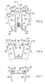
- FIG. 5 there is shown a first part 20 of a two-part annulus filler 21.
- a portion of the radially outer region of a compressor fan rotor disc 22 is also shown.
- the radially outer surface of the rotor disc 22 is provided with a plurality of circumferentially spaced-apart retention grooves 23 (parts of two such grooves being illustrated in Figure 5 ) for receiving and retaining the root portions 24 of respective fan blades 25.
- the retention grooves 23 may be straight or curved and extend generally in the axial direction of the engine.
- the retention grooves 23 have a generally "fir-tree"-" shaped cross-sectional profile and the root portions 24 of the blades have a complementary fir-tree profile in order to provide an accurate and strong connection between each blade and the rotor disc 22.
- the retention grooves 23 and the root portions 24 of the blades could have complementary dovetail profiles instead.
- the first part 20 of the annulus filler takes the form of a generally elongate body extending in the axial direction of the engine.
- Figure 5 illustrates the body part 20 in transverse cross-section and shows it in an initial installation configuration which will be described in more detail below.
- the body part is resiliently deformable and is configured such that in its natural relaxed condition, it adopts the installation configuration illustrated in Figure 5 .
- the body part is preferably formed from metal such as aluminium, titanium or magnesium alloys and may be extruded or metal injection moulded.
- the body part 20 has a pair of spaced-apart arms 26 which are arranged so as to extend generally radially outwardly from a mounting region 27.
- the mounting region 27 forms an integral part of the body 20 and serves to interconnect the two arms 26 at their radially innermost ends.
- the mounting region 27 has a curved profile and is thus configured for intimate engagement against the outer surface of the rotor disc 22.
- Figure 5 shows the body part 20 connected to the rotor disc 22.
- This connection can be effected in a number of alternative ways.
- the mounting region 27 of the first part 20 is provided with a number of mounting apertures 28 at spaced-apart positions along its axial length.
- Each mounting aperture 28 is configured to receive therethrough the threaded shank 29 of a mounting bolt 30 for threaded engagement within an aligned mounting recess 31 provided in the outer region of the rotor disc 22.
- the particular mounting arrangement illustrated in Figure 5 uses generally radially oriented mounting bolts 30.
- alternative mounting arrangements could also be used which could, for example, use axially orientated mounting bolts or the like. Other mounting arrangements are also possible.
- Each arm 26 supports an enlarged formation 32 at its radially outermost end, each formation extending both inwardly into the space defined between the two arms 26 and outwardly so as to extend generally towards the respective adjacent rotor blade 25. More particularly, each formation 32 presents a generally radially-outwardly directed surface 33 and defines an axially extending side edge 34.
- the body part 20 is provided with a pair of sealing members 35 each of which is mounted along a respective side edge 34.
- each formation 32 extending generally inwardly into the space defined between the two supporting arms 26 is configured so as to define a generally axially extending groove 36.
- the two grooves 36 are arranged so as to oppose one another and are each open in a direction facing the opposite groove.
- Figure 5 shows the resilient body part 20 in a relaxed condition in which it adopts an initial installation configuration.
- each outwardly extending sealing member 35 is spaced from the adjacent rotor blade 25 by a clearance gap G, whilst the inwardly directed regions of the formations 32 defining the opposed grooves 36 are spaced from one another by a clearance gap g which is of a size sufficient to permit the passage therethrough of a tool for use in installing and tightening the mounting bolts 30.
- This configuration of the body part 20 thus permits the rotor blades 25 to be easily mounted to the rotor disc 22 after the body part 20 has been mounted to the rotor disc 22.
- each side of the body part 20 and the adjacent rotor blades 25 allows the rotor blades 25 to be properly located and offered up to the rotor disc 22 without hindrance by body parts 20, the gaps allowing movement of the blades from side to side as might be necessary as they are manipulated into engagement with their respective retention grooves 23.
- the body parts 20 of respective annulus fillers will usually be mounted to the rotor disc prior to the rotor blades 25, the configuration of the body part would also permit an alternative assembly order in which the rotor blades 25 are mounted to the rotor disc first, followed by the body parts.
- the clearance gap g between the inwardly directed regions of the formations 32 allows a person fitting the annulus filler to the rotor disc 22 to view the mounting region 27 in a generally radial direction denoted by arrow 37, through the gap, thereby allowing accurate alignment of the mounting apertures 28 with respective mounting recesses 31 formed in the outer periphery of the rotor disc 22.
- the clearance gap g also permits the passage therethrough of a tool for installation and tightening of the mounting bolts 30, whilst simultaneously allowing clear sight of the bolts. As will be appreciated, it will be generally easier to mount the body part 20 to the rotor disc in this manner in the absence of the rotor blades 25 as the fitter will be afforded a clearer view and easier tool access.
- the second part 38 takes the form of an elongate slider which is configured for engagement with the body part 20 in a manner effective to urge the body part 20 against the bias of its inherent resiliency, so as to move from the initial installation configuration illustrated in Figure 5 towards an alternate, operational configuration as illustrated in Figure 6 .
- the second part, or slider 38 has a radial cross-sectional profile which presents a generally smooth radially outer surface 39.
- the slider 38 is provided with a pair of oppositely directed flanges 40 running along respective side edges. As thus illustrated in Figure 6 , the oppositely directed side flanges 40 of the slider 38 are thus configured for sliding engagement within respective grooves 36 formed in the body part 20. After the rotor blades 25 have been connected to the rotor disc, the slider 38 may thus be slidingly engaged with the body part 20 in a substantially axial direction relative to the axis of the engine (i.e. into the page as viewing Figure 6 ).
- the radially outer surfaces 33 of the body part 20 lie substantially flush with the radially outer surface 39 of the slider 38.
- the flush-lying surfaces 33, 39 thus cooperate to define respective regions of an airflow surface for air drawn through the engine, the airflow surface extending generally between the adjacent rotor blades 25.
- the slider 38 could either be made from suitable metal material such as aluminium, titanium or magnesium alloys. Alternatively, however, the slider 38 could be formed from plastic material.
- material for the slider may be a carbon- or glass-fibre reinforced thermoplastic, such as Torlon TM 5030/7030 (polyamide-imide) from Solvay Advanced Polymers.
- Torlon TM 5030/7030 polyamide-imide
- Such a slider could be formed by injection or compression moulding.
- the slider could be formed from fibre reinforced epoxy, for example by compression moulding. Injection moulding generally requires short reinforcing fibres. Compression moulding could use longer fibres.
- the two-part annulus filler 21 of the present invention offers significant advantages over prior art annulus filler designs in that it permits an installation process in which the fitter has substantially unobstructed sight of the mounting region 27 of the annulus filler as it is offered up to and connected to the rotor disc, and substantially unobstructed sight of the flanges 40 of the slider 38 and the cooperating grooves 36 formed in the body part as the slider is offered up to and engaged with the body part, even in the event that the adjacent rotor blades have already been assembled.
- This significantly reduces the potential for mal-assembly of the annulus filler which in turn reduces the likelihood of the annulus filler becoming detached from the rotor in service.
- annulus filler design of the present invention also provides distinct advantages in the event of a fan-blade-off event.
- the generally V-shaped transverse cross-sectional profile of the body part 20 when in its operational configuration, and its deformable nature, provides a degree of flexibility that allows the annulus filler to rotate relative to the axis of the engine when pushed from the side by a deflecting rotor blade. Should the filler nevertheless fail due to the forces exerted on it by an adjacent deflecting blade, it is likely that only the slider 38 (and perhaps also the radially outer region of the arms 26 supporting the formations 32) will fail, leaving intact the radially inner region of the arms, which will thus remain securely connected to the rotor disc.
- the mass and therefore energy of the resulting debris will thus be reduced in comparison to the sort of failure experienced with prior art annulus fillers. This reduces the amount of shrapnel moving around in the fan-case of the engine, thereby reducing the risk of high energy debris causing further damage to the engine. Also, by making the slider 38 from plastic or composite materials proposed above rather than metal, the weight of any such shrapnel will be significantly reduced, thereby reducing the likelihood of the shrapnel causing serious damage to the engine.
- FIG. 7 there is illustrated an alternative embodiment of the present invention in which the side flanges 40 of the slider 38, and the cooperating axial grooves 36 of the body part 20 have a modified cross-sectional profile.
- the flanges 40 of the slider 38 are each provided with a small radially outwardly directed lip 42.
- the cooperating grooves 36 in the body part are configured so as to have a corresponding re-entrant region 43 sized and shaped to receive a respective side lip 42 of the slider 38.
- This modified form of engagement between the slider 38 and the body part 20 serves to further resist possible release of the slider 38 due to circumferential deflection of the arms 26 of the body part 20 during operation of the engine. Engagement of the side lips 42 within the re-entrant regions 43 of the grooves 36 is thus effective to prevent disengagement of the side flanges 40 of the slider 38 from the grooves 36 during significant circumferential deflection of the arms 26.
Landscapes
- Engineering & Computer Science (AREA)
- Mechanical Engineering (AREA)
- General Engineering & Computer Science (AREA)
- Structures Of Non-Positive Displacement Pumps (AREA)
- Turbine Rotor Nozzle Sealing (AREA)
Abstract
Description
- The present invention relates to annulus fillers for bridging gaps between adjacent blades of a gas turbine engine stage.
- Conventionally, each compressor rotor stage of a gas turbine engine comprises a plurality of radially extending blades mounted on a rotor disc. The blades are mounted on the disc by inserting a root portion of the blade in a complementary retention groove in the outer face of the disc periphery. To ensure a smooth radially inner surface for air to flow over as it passes through the stage, annulus fillers are used to bridge the spaces between adjacent blades. Typically, seals between the annulus fillers and the adjacent fan blades are also provided by resilient strips bonded to the annulus fillers adjacent the fan blades.
- Annulus fillers of this type are commonly used in the fan stage of gas turbine engines. The fillers may be manufactured from relatively lightweight materials and, in the event of damage, may be replaced independently of the blades.
- It is known to provide annulus fillers with features for removably attaching them to the rotor disc. For example, it has been proposed to provide annulus fillers with axially spaced hook members, the hook members sliding into engagement with respective parts of the rotor disc.
Figure 1 shows an example of such an annulus filler viewed from the side, andFigure 2 shows the annulus filler fitted to the rotor disc as viewed in transverse cross-section. - In use, the upper surface or
lid 2 of the annulus filler 1 bridges the gap between two adjacent fan blades 3 (one of which is shown in outline inFigure 2 ) and defines the inner wall of the flow annulus of a fan stage. The annulus filler 1 is mounted on a fan disc 4 by twohook members retention flange 8 provided at the forward end of the annulus filler. Along its rear edge, the annulus filler is provided with arear lip 9 which is configured to fit under a rear fan seal 10 located axially behind the rotor disc 4 to limit deflection under running conditions. Similarly, the front edge of the annulus filler defines afront lip 11 which is configured to fit under aspinner fairing 12 located axially ahead of the annulus filler. The two opposed side faces 13, 14 of the annulus filler are provided with respective seal strips (not shown) and confront the aerofoil surfaces of the adjacent fan blades 3 in a sealing manner. - As illustrated in more detail in
Figure 3 , theretention flange 8 carries a forwardly extending spigot orpin 15. The spigot orpin 15 is arranged for engagement within a corresponding aperture or recess provided in the support ring 7. At a position circumferentially adjacent the spigot orpin 15, the retention flange is also provided with a mounting aperture 16 which is arranged for co-alignment with a corresponding mounting aperture (not shown) provided through the support ring 7. The co-aligned mounting apertures are sized to receive a mounting bolt. Thus, it will be appreciated that theretention flange 8 is pinned and bolted to the front support ring 7. -
Figure 4 illustrates the typical form of therear hook member 6, as viewed from behind. As can be seen, the hook member defines anarcuate channel 17. Thechannel 17 is curved in such a manner as to be centred on the rotational axis of the engine (not shown), and cooperates with a correspondingly arcuate hook on the rotor disc 4. Thefront hook member 5 has a similar arcuate configuration. - A problem which has been experienced with prior art annulus fillers of the general type described above is that of reliable installation during engine assembly. As will be appreciated by those of skill in the art, the annulus filler must be fitted after the radially extending fan blades have been attached to the rotor disc. This means when the fitter then comes to install the annulus fillers between adjacent blades, his or her line of sight is obstructed by the presence of the fan blades. Also, the unitary construction of the annulus filler exacerbates this problem, because the
filler lid 2 also obstructs the fitter's view when attempting to engage thehook members rear hook member 6 has been found to be a particular problem in this regard and has been attributed to the release of annulus fillers in operation. - Annulus fillers of the prior-art type described above are self-loading in the sense that, as a rotating component, the majority of forces on the filler are generated by its own mass. This can be modelled as an approximately radial force acting through the centre of gravity of the annulus filler. However, in the event of a bird-strike, or a fan blade otherwise becoming detached from the rotor (i.e. a so-called "fan-blade-off" event), the blades can apply tangential pushing forces to the adjacent annulus fillers thereby tending to pinch the annulus fillers between the blades as the blades pivot tangentially in their retention grooves. This can cause the annulus fillers to become detached from the rotor. In this regard, it is to be noted that a bird-strike or fan-blade-off event creates substantial imbalance in the rotor, and so even the remaining fan blades can deflect considerably due to their tips impinging on the outer casing surrounding the rotor. Thus it is not unknown to lose annulus fillers from circumferential positions well away from the primary release blade.
- It has been found that the above-described configuration of annulus filler can increase the likelihood of the filler failing under the action of the tangential forces applied to it by the adjacent fan blades. Due to the curved nature of the interface between the
hook members retention flange 8 and thefront hook member 5. As will be appreciated, failure of annulus fillers in this manner is problematic as it increases the amount of shrapnel moving around inside engine during a bird-strike or fan-blade-off event which can have serious consequences for the integrity of the engine. - It is therefore an object of the present invention to provide an improved annulus filler.
According to a first aspect of the invention there is provided a method of mounting an annulus filler to a rotor disc of a gas turbine engine, the annulus filler bridging the gap between two adjacent blades attached to the rotor disc, the annulus filler comprising: - a first part which is connectable to the rotor disc between the positions of said adjacent blades, and a separate second part configured for engagement with the first part, characterised in that the method comprises the steps of installing the first part on the rotor disc in an installation configuration in which it is spaced from each said blade by a respective clearance gap, and subsequently engaging the second part with the first part to urge the first part from the installation configuration to an operational configuration in which it substantially contacts each of said blades.
- The first part may be installed on the rotor disc in the installation configuration prior to connection of said blades to said rotor disc.
- The step of installing the first part to the disc may include securing the first part on the rotor disc using a mechanical fastener. The mechanical fastener may be releasable and include a threaded shank and corresponding receptacle, rivet or other appropriate device.
- The step of installing the first part to the disc may include the step of inspecting the mechanical fastener after securing the first part on the rotor disc and prior to the engagement of the second part with the first part.
- The first part may have, in transverse cross-section, a pair of spaced-apart and generally radially oriented arms, wherein on engagement of said second part with said first part the radially outer regions of said arms are urged further apart from one another.
- The second part may be slid into engagement with said first part in a direction perpendicular to the transverse cross-section.
- The second part may be removably engaged with axial grooves provided in each arm with each groove receiving a respective edge of said second part.
- The first part may be provided with a pair of seals that contact and substantially seal against respective blades when in said operational configuration.
- According to a second aspect of the present invention, there is provided an annulus filler for mounting to a rotor disc of a gas turbine engine and for bridging the gap between two adjacent blades attached to the rotor disc, the annulus filler comprising:
- a first part which is connectable to the rotor disc between the positions of said adjacent blades, and a separate second part configured for engagement with the first part, characterised in that said first part has, in transverse cross-section, a pair of spaced-apart and generally radially orientated arms resiliently biased towards an installation configuration in which the first part is spaced from each said blade by a respective clearance gap (G), and an operational configuration in which it substantially contacts each of said blades, wherein engagement of the second part with the first part is effective to urge the first part from said installation configuration to said operational configuration and thus towards contact with said blades.
- The first and second parts may be configured to allow a procedure for mounting the annulus filler to the rotor disc, the procedure having a first step in which the first part is connected to the rotor disc without the second part and whilst in said installation configuration, and a subsequent second step in which the second part is engaged with the first part to urge the first part from said installation configuration to said operational configuration and thus towards contact with said blades.
- Said first step may occur prior to connection of said blades to said rotor disc, and said second step may occur after connection of said blades to said rotor disc.
- The first part may have at least one mounting region for connection to the rotor disc and may be configured to allow the or each mounting region to remain substantially visible from a radially outer viewpoint after the first part is mounted to the rotor disc.
- Conveniently, said first and second parts may be configured to allow the engaging regions of said first and second parts to remain substantially visible from a radially outer viewpoint (37) during said second step.
- The second part may be configured for engagement with said first part in a sliding manner, in a substantially axial direction.
- The first part may be configured such that when in said installation configuration, the arms lie substantially parallel to one another in transverse cross-section.
- Each arm may be provided with an axial groove configured to slideably receive a respective edge of said second part.
- Said first part may be provided with a pair of seals to contact and substantially seal against respective blades when in said operational configuration. Each said seal may be provided in the radially outer region of a respective said arm.
- The first part may be formed from a first material and the second part formed from a different second material. More particularly, the first part may be formed from a metal material. The second part may be formed from plastics material.
- At least one of said first and second parts may define part of an airflow surface for air drawn through the engine.
- Said first and second parts may define respective regions of an airflow surface for air drawn through the engine, the first and second parts having respective outer surfaces which lie substantially flush when the parts are engaged with one another.
- A stage for a gas turbine engine may have: a rotor disc; a plurality of circumferentially spaced apart blades attached to the rotor disc; and a plurality of annulus fillers in accordance with the second aspect of the invention. Optional features of the first or second aspect may apply, as appropriate.
- A stage for a gas turbine engine may have: a rotor disc; a plurality of circumferentially spaced apart blades attached to the rotor disc; and a plurality of annulus fillers mounted to the rotor disc in accordance with the first aspect of the invention. Optional features of the first or second aspect may apply, as appropriate.
- So that the invention may be more readily understood, and so that further features thereof may be appreciated, embodiments of the invention will now be described by way of example with reference to the accompanying drawings in which:
-
Figure 1 shows a prior-art annulus filler, viewed from the side; -
Figure 2 shows the annulus filler ofFigure 1 , installed in a gas turbine engine; -
Figure 3 is an enlarged view of part of the annulus filler shown inFigures 1 and 2 , as viewed from the front; -
Figure 4 is an enlarged view of another part of the annulus filler shown inFigures 1 and 2 , as viewed from the rear; -
Figure 5 is a transverse cross-sectional view showing a first part of an annulus filler in accordance with the present invention connected to a rotor disc between the positions of a pair of adjacent blades, and in a first configuration; -
Figure 6 is a cross-sectional view similar to that ofFigure 5 , showing the first part in combination with a second part of the annulus filler, and with the first part in a second configuration in which it contacts the adjacent blades; and -
Figure 7 is a transverse cross-sectional view taken through a region of an annulus filler in accordance with another embodiment of the present invention. - Referring now in more detail to
Figure 5 , there is shown afirst part 20 of a two-part annulus filler 21. A portion of the radially outer region of a compressorfan rotor disc 22 is also shown. In a generally conventional manner, the radially outer surface of therotor disc 22 is provided with a plurality of circumferentially spaced-apart retention grooves 23 (parts of two such grooves being illustrated inFigure 5 ) for receiving and retaining theroot portions 24 ofrespective fan blades 25. Theretention grooves 23 may be straight or curved and extend generally in the axial direction of the engine. In the particular arrangement illustrated inFigure 5 , theretention grooves 23 have a generally "fir-tree"-" shaped cross-sectional profile and theroot portions 24 of the blades have a complementary fir-tree profile in order to provide an accurate and strong connection between each blade and therotor disc 22. However, it is to be appreciated that in alternative embodiments, particularly those intended for use in the fan of a gas turbine engine, theretention grooves 23 and theroot portions 24 of the blades could have complementary dovetail profiles instead. - The
first part 20 of the annulus filler takes the form of a generally elongate body extending in the axial direction of the engine.Figure 5 illustrates thebody part 20 in transverse cross-section and shows it in an initial installation configuration which will be described in more detail below. The body part is resiliently deformable and is configured such that in its natural relaxed condition, it adopts the installation configuration illustrated inFigure 5 . The body part is preferably formed from metal such as aluminium, titanium or magnesium alloys and may be extruded or metal injection moulded. - In transverse cross-section (as shown in
Figure 5 ), thebody part 20 has a pair of spaced-apartarms 26 which are arranged so as to extend generally radially outwardly from a mountingregion 27. The mountingregion 27 forms an integral part of thebody 20 and serves to interconnect the twoarms 26 at their radially innermost ends. The mountingregion 27 has a curved profile and is thus configured for intimate engagement against the outer surface of therotor disc 22. -
Figure 5 shows thebody part 20 connected to therotor disc 22. This connection can be effected in a number of alternative ways. In the particular arrangement illustrated, the mountingregion 27 of thefirst part 20 is provided with a number of mountingapertures 28 at spaced-apart positions along its axial length. Each mountingaperture 28 is configured to receive therethrough the threadedshank 29 of a mountingbolt 30 for threaded engagement within an aligned mountingrecess 31 provided in the outer region of therotor disc 22. Thus, it will be appreciated that the particular mounting arrangement illustrated inFigure 5 uses generally radially oriented mountingbolts 30. However, as indicated above, alternative mounting arrangements could also be used which could, for example, use axially orientated mounting bolts or the like. Other mounting arrangements are also possible. - Each
arm 26 supports anenlarged formation 32 at its radially outermost end, each formation extending both inwardly into the space defined between the twoarms 26 and outwardly so as to extend generally towards the respectiveadjacent rotor blade 25. More particularly, eachformation 32 presents a generally radially-outwardly directedsurface 33 and defines an axially extendingside edge 34. In the arrangement illustrated inFigure 5 , thebody part 20 is provided with a pair of sealingmembers 35 each of which is mounted along arespective side edge 34. - The region of each
formation 32 extending generally inwardly into the space defined between the two supportingarms 26 is configured so as to define a generally axially extendinggroove 36. The twogrooves 36 are arranged so as to oppose one another and are each open in a direction facing the opposite groove. - As indicated above,
Figure 5 shows theresilient body part 20 in a relaxed condition in which it adopts an initial installation configuration. In this configuration, it is to be noted that each outwardly extending sealingmember 35 is spaced from theadjacent rotor blade 25 by a clearance gap G, whilst the inwardly directed regions of theformations 32 defining theopposed grooves 36 are spaced from one another by a clearance gap g which is of a size sufficient to permit the passage therethrough of a tool for use in installing and tightening the mountingbolts 30. This configuration of thebody part 20 thus permits therotor blades 25 to be easily mounted to therotor disc 22 after thebody part 20 has been mounted to therotor disc 22. The clearance gaps G between each side of thebody part 20 and theadjacent rotor blades 25 allows therotor blades 25 to be properly located and offered up to therotor disc 22 without hindrance bybody parts 20, the gaps allowing movement of the blades from side to side as might be necessary as they are manipulated into engagement with theirrespective retention grooves 23. However, it is to be noted that whilst it is envisaged that thebody parts 20 of respective annulus fillers will usually be mounted to the rotor disc prior to therotor blades 25, the configuration of the body part would also permit an alternative assembly order in which therotor blades 25 are mounted to the rotor disc first, followed by the body parts. - Additionally, the clearance gap g between the inwardly directed regions of the
formations 32 allows a person fitting the annulus filler to therotor disc 22 to view the mountingregion 27 in a generally radial direction denoted byarrow 37, through the gap, thereby allowing accurate alignment of the mountingapertures 28 with respective mounting recesses 31 formed in the outer periphery of therotor disc 22. The clearance gap g also permits the passage therethrough of a tool for installation and tightening of the mountingbolts 30, whilst simultaneously allowing clear sight of the bolts. As will be appreciated, it will be generally easier to mount thebody part 20 to the rotor disc in this manner in the absence of therotor blades 25 as the fitter will be afforded a clearer view and easier tool access. - Turning now to consider
Figure 6 , the above-describedbody part 20 of theannulus filler 21 is shown in combination with a separatesecond part 38. Thesecond part 38 takes the form of an elongate slider which is configured for engagement with thebody part 20 in a manner effective to urge thebody part 20 against the bias of its inherent resiliency, so as to move from the initial installation configuration illustrated inFigure 5 towards an alternate, operational configuration as illustrated inFigure 6 . - The second part, or
slider 38, has a radial cross-sectional profile which presents a generally smooth radiallyouter surface 39. Theslider 38 is provided with a pair of oppositely directedflanges 40 running along respective side edges. As thus illustrated inFigure 6 , the oppositely directedside flanges 40 of theslider 38 are thus configured for sliding engagement withinrespective grooves 36 formed in thebody part 20. After therotor blades 25 have been connected to the rotor disc, theslider 38 may thus be slidingly engaged with thebody part 20 in a substantially axial direction relative to the axis of the engine (i.e. into the page as viewingFigure 6 ). In this regard, it is to be noted that a person fitting the annulus filler to therotor disc 22 is afforded a clear view of theslider 38 in theradial viewing direction 37 as it is engaged with thebody part 20, thereby ensuring reliable connection of the two components. - Sliding engagement of the
slider 38 with thebody part 20 is effective to drive thesupport arms 26 outwardly, as indicated byarrows 41 inFigure 5 , such that they move from being substantially parallel to one another as illustrated inFigure 5 to being divergent as illustrated inFigure 6 . It will thus be appreciated that in the configuration illustrated inFigure 6 , the transverse cross-sectional profile of thebody part 20 is generally V-shaped, and in this configuration the clearance gaps G between the side edges of the two sealingmembers 35 and theadjacent rotor blades 25 have been closed such that the sealingmembers 35 are brought into close and intimate sealing contact with the surfaces of therotor blades 25. - When the
slider 38 is fully engaged with thebody 20 such that thebody 20 adopts the operational configuration illustrated inFigure 6 , the radiallyouter surfaces 33 of thebody part 20 lie substantially flush with the radiallyouter surface 39 of theslider 38. The flush-lyingsurfaces adjacent rotor blades 25. - It is envisaged that the
slider 38 could either be made from suitable metal material such as aluminium, titanium or magnesium alloys. Alternatively, however, theslider 38 could be formed from plastic material. For example, material for the slider may be a carbon- or glass-fibre reinforced thermoplastic, such as Torlon™ 5030/7030 (polyamide-imide) from Solvay Advanced Polymers. Such a slider could be formed by injection or compression moulding. Alternatively, the slider could be formed from fibre reinforced epoxy, for example by compression moulding. Injection moulding generally requires short reinforcing fibres. Compression moulding could use longer fibres. - As will thus be appreciated, the two-
part annulus filler 21 of the present invention offers significant advantages over prior art annulus filler designs in that it permits an installation process in which the fitter has substantially unobstructed sight of the mountingregion 27 of the annulus filler as it is offered up to and connected to the rotor disc, and substantially unobstructed sight of theflanges 40 of theslider 38 and the cooperatinggrooves 36 formed in the body part as the slider is offered up to and engaged with the body part, even in the event that the adjacent rotor blades have already been assembled. This significantly reduces the potential for mal-assembly of the annulus filler which in turn reduces the likelihood of the annulus filler becoming detached from the rotor in service. - Additionally, the annulus filler design of the present invention also provides distinct advantages in the event of a fan-blade-off event. The generally V-shaped transverse cross-sectional profile of the
body part 20 when in its operational configuration, and its deformable nature, provides a degree of flexibility that allows the annulus filler to rotate relative to the axis of the engine when pushed from the side by a deflecting rotor blade. Should the filler nevertheless fail due to the forces exerted on it by an adjacent deflecting blade, it is likely that only the slider 38 (and perhaps also the radially outer region of thearms 26 supporting the formations 32) will fail, leaving intact the radially inner region of the arms, which will thus remain securely connected to the rotor disc. As only the slider 38 (and perhaps also a portion of the body part 20) is thus likely to be released under such circumstances, the mass and therefore energy of the resulting debris will thus be reduced in comparison to the sort of failure experienced with prior art annulus fillers. This reduces the amount of shrapnel moving around in the fan-case of the engine, thereby reducing the risk of high energy debris causing further damage to the engine. Also, by making theslider 38 from plastic or composite materials proposed above rather than metal, the weight of any such shrapnel will be significantly reduced, thereby reducing the likelihood of the shrapnel causing serious damage to the engine. - Turning now to consider
Figure 7 , there is illustrated an alternative embodiment of the present invention in which theside flanges 40 of theslider 38, and the cooperatingaxial grooves 36 of thebody part 20 have a modified cross-sectional profile. In this arrangement, it will be seen that theflanges 40 of theslider 38 are each provided with a small radially outwardly directedlip 42. The cooperatinggrooves 36 in the body part are configured so as to have a correspondingre-entrant region 43 sized and shaped to receive arespective side lip 42 of theslider 38. This modified form of engagement between theslider 38 and thebody part 20 serves to further resist possible release of theslider 38 due to circumferential deflection of thearms 26 of thebody part 20 during operation of the engine. Engagement of theside lips 42 within there-entrant regions 43 of thegrooves 36 is thus effective to prevent disengagement of theside flanges 40 of theslider 38 from thegrooves 36 during significant circumferential deflection of thearms 26. - When used in this specification and claims, the terms "comprises" and "comprising" and variations thereof mean that the specified features, steps or integers are included. The terms are not to be interpreted to exclude the presence of other features, steps or components.
- The features disclosed in the foregoing description, or in the following claims, or in the accompanying drawings, expressed in their specific forms or in terms of a means for performing the disclosed function, or a method or process for obtaining the disclosed results, as appropriate, may, separately, or in any combination of such features, be utilised for realising the invention in diverse forms thereof.
- While the invention has been described in conjunction with the exemplary embodiments described above, many equivalent modifications and variations will be apparent to those skilled in the art when given this disclosure. Accordingly, the exemplary embodiments of the invention set forth above are considered to be illustrative and not limiting. Various changes to the described embodiments may be made without departing from the spirit and scope of the invention.
Claims (15)
- A method of mounting an annulus filler (21) to a rotor disc (22) of a gas turbine engine, the annulus filler bridging the gap between two adjacent blades (25) attached to the rotor disc, the annulus filler (21) comprising:a first part (20) which is connectable to the rotor disc (22) between the positions of said adjacent blades (25), and a separate second part (38) configured for engagement with the first part (20), characterised in that the method comprises the steps of installing the first part on the rotor disc in an installation configuration in which it is spaced from each said blade (25) by a respective clearance gap (G), and subsequently engaging the second part with the first part to urge the first part from the installation configuration to an operational configuration in which it substantially contacts each of said blades.
- A method of mounting an annulus filler according to claim 1, wherein the first part is installed on the rotor disc in the installation configuration prior to connection of said blades (25) to said rotor disc (22).
- A method of mounting an annulus filler according to claim 2, wherein the step of installing the first part to the disc includes securing the first part on the rotor disc using a mechanical fastener.
- A method of mounting an annulus filler according to claim 2, wherein the step of installing the first part to the disc includes the step of inspecting the mechanical fastener after securing the first part on the rotor disc and prior to the engagement of the second part with the first part.
- A method of mounting an annulus filler according to any preceding claim, wherein said first part (20) has, in transverse cross-section, a pair of spaced-apart and generally radially oriented arms (26), wherein on engagement of said second part (38) with said first part the radially outer regions (32) of said arms (26) are urged further apart from one another.
- A method of mounting an annulus filler according to claim 5, wherein the second part is slid into engagement with said first part in a direction perpendicular to the transverse cross-section.
- A method of mounting an annulus filler according to claim 6, wherein the second part removably engages with axial grooves provided in each arm with each groove receiving a respective edge of said second part.
- A method mounting an annulus filler according to any preceding claim, wherein said first part (20) is provided with a pair of seals (35) that contact and substantially seal against respective blades (25) when in said operational configuration.
- An annulus filler (21) for mounting to a rotor disc (22) of a gas turbine engine and for bridging the gap between two adjacent blades (25) attached to the rotor disc, the annulus filler (21) comprising:a first part (20) which is connectable to the rotor disc (22) between the positions of said adjacent blades (25), and a separate second part (38) configured for engagement with the first part (20), characterised in that said first part has, in transverse cross-section, a pair of spaced-apart and generally radially orientated arms (26) resiliently biased towards an installation configuration in which the first part is spaced from each said blade (25) by a respective clearance gap (G), and an operational configuration in which it substantially contacts each of said blades, wherein engagement of the second part (38) with the first part (20) is effective to urge the first part (20) from said installation configuration to said operational configuration and thus towards contact with said blades (25).
- An annulus filler according to claim 9, wherein said first and second parts are configured to allow a procedure for mounting the annulus filler (21) to the rotor disc (22), the procedure having a first step in which the first part (20) is connected to the rotor disc (22) without the second part (38) and whilst in said installation configuration, and a subsequent second step in which the second part (38) is engaged with the first part (20) to urge the first part (20) from said installation configuration to said operational configuration and thus towards contact with said blades (25).
- An annulus filler according to claim 9 or claim 10, wherein said first part (20) has at least one mounting region (27) for connection to the rotor disc (22) and is configured to allow the or each mounting region (27) to remain substantially visible from a radially outer viewpoint (37) after the first part is mounted to the rotor disc.
- An annulus filler according to any of claim 9 to claim 11, wherein the second part (38) is configured for engagement with said first part (20) in a sliding manner, in a substantially axial direction.
- An annulus filler according any one of claims 9 to 12, wherein each said arm (26) is provided with an axial groove (36) configured to slideably receive a respective edge (40) of said second part (38).
- An annulus filler according to any one of claims 9 to 13, wherein said first part (20) is provided with a pair of seals (35) to contact and substantially seal against respective blades (25) when in said operational configuration.
- A stage for a gas turbine engine having: a rotor disc (22); a plurality of circumferentially spaced apart blades (25) attached to the rotor disc; and a plurality of annulus fillers (21) according to any one of claims 9 to 14 bridging the gaps between adjacent blades (25).
Applications Claiming Priority (1)
| Application Number | Priority Date | Filing Date | Title |
|---|---|---|---|
| GBGB0910752.5A GB0910752D0 (en) | 2009-06-23 | 2009-06-23 | An annulus filler for a gas turbine engine |
Publications (2)
| Publication Number | Publication Date |
|---|---|
| EP2267277A2 true EP2267277A2 (en) | 2010-12-29 |
| EP2267277A3 EP2267277A3 (en) | 2017-11-29 |
Family
ID=40972577
Family Applications (1)
| Application Number | Title | Priority Date | Filing Date |
|---|---|---|---|
| EP10165254.3A Withdrawn EP2267277A3 (en) | 2009-06-23 | 2010-06-08 | Annulus filler and method of mounting the annulus filler to a rotor disc of a gas turbine engine |
Country Status (3)
| Country | Link |
|---|---|
| US (1) | US8596981B2 (en) |
| EP (1) | EP2267277A3 (en) |
| GB (1) | GB0910752D0 (en) |
Cited By (7)
| Publication number | Priority date | Publication date | Assignee | Title |
|---|---|---|---|---|
| FR2987086A1 (en) * | 2012-02-22 | 2013-08-23 | Snecma | LINEAR JOINT OF PLATFORM INTER-AUBES |
| WO2014051799A2 (en) | 2012-06-29 | 2014-04-03 | United Technologies Corporation | Fairing assembly |
| WO2015088593A1 (en) | 2013-12-13 | 2015-06-18 | United Technologies Corporation | Fan platform edge seal |
| US9228444B2 (en) | 2011-11-15 | 2016-01-05 | Rolls-Royce Plc | Annulus filler |
| US12012857B2 (en) | 2022-10-14 | 2024-06-18 | Rtx Corporation | Platform for an airfoil of a gas turbine engine |
| RU230056U1 (en) * | 2024-06-19 | 2024-11-12 | Публичное Акционерное Общество "Одк-Сатурн" | Device for limiting air flow under the interblade shelves of the support disks of the fan blades of a turbojet engine |
| FR3159627A1 (en) * | 2024-02-27 | 2025-08-29 | Safran Aircraft Engines | INTER-BLADE PLATFORM FOR AN AIRCRAFT TURBOMACHINE PROPELLER |
Families Citing this family (9)
| Publication number | Priority date | Publication date | Assignee | Title |
|---|---|---|---|---|
| US20120156045A1 (en) * | 2010-12-17 | 2012-06-21 | General Electric Company | Methods, systems and apparatus relating to root and platform configurations for turbine rotor blades |
| US9682450B2 (en) * | 2013-01-11 | 2017-06-20 | United Technologies Corporation | Gas turbine engine nose cone attachment configuration |
| JP6221544B2 (en) * | 2013-09-18 | 2017-11-01 | 株式会社Ihi | Seal for turbofan engine |
| DE102014217887A1 (en) * | 2014-09-08 | 2016-03-10 | Rolls-Royce Deutschland Ltd & Co Kg | Filling elements of a fan of a gas turbine |
| US10746031B2 (en) | 2017-07-18 | 2020-08-18 | Rolls-Royce Corporation | Annulus filler |
| US11078839B2 (en) | 2018-01-22 | 2021-08-03 | Rolls-Royce Corporation | Composite nosecone |
| FR3091563B1 (en) * | 2019-01-04 | 2023-01-20 | Safran Aircraft Engines | Improved inter-blade platform seal |
| US11421538B2 (en) | 2020-05-12 | 2022-08-23 | Rolls-Royce Corporation | Composite aerofoils |
| US11506083B2 (en) | 2020-06-03 | 2022-11-22 | Rolls-Royce Corporalion | Composite liners for turbofan engines |
Family Cites Families (27)
| Publication number | Priority date | Publication date | Assignee | Title |
|---|---|---|---|---|
| US2935296A (en) * | 1951-12-26 | 1960-05-03 | Gen Motors Corp | Blade retaining means |
| FR1341910A (en) * | 1962-12-20 | 1963-11-02 | Cem Comp Electro Mec | Sheet metal blades |
| US3245657A (en) * | 1963-09-10 | 1966-04-12 | Gen Motors Corp | Turbine rotor |
| GB1232506A (en) * | 1969-10-28 | 1971-05-19 | ||
| GB1331209A (en) * | 1969-10-28 | 1973-09-26 | Secr Defence | Bladed rotors for fluid flow machines |
| BE794573A (en) * | 1972-02-02 | 1973-05-16 | Gen Electric | AUBES FIXING DEVICE |
| SU480882A1 (en) | 1973-04-18 | 1975-08-15 | Специальное Конструкторское Бюро Транснефтеавтоматика" | Drive unit |
| DE3121136A1 (en) | 1981-05-27 | 1982-12-16 | Magnetic-Elektromotoren GmbH, 7867 Maulburg | Drive especially for up-and-over doors and the like |
| GB2171151B (en) | 1985-02-20 | 1988-05-18 | Rolls Royce | Rotors for gas turbine engines |
| US4875830A (en) * | 1985-07-18 | 1989-10-24 | United Technologies Corporation | Flanged ladder seal |
| US5131814A (en) * | 1990-04-03 | 1992-07-21 | General Electric Company | Turbine blade inner end attachment structure |
| US5259728A (en) * | 1992-05-08 | 1993-11-09 | General Electric Company | Bladed disk assembly |
| GB2299834B (en) * | 1995-04-12 | 1999-09-08 | Rolls Royce Plc | Gas turbine engine rotary disc |
| DE19548593A1 (en) | 1995-12-23 | 1997-07-10 | Behr Gmbh & Co | Mechanism for conversion of rotation to translation and vice-versa |
| CZ290598B6 (en) * | 1997-04-30 | 2002-08-14 | Vladislav Ing. Csc. Poulek | Power-operated mechanism for swinging wings |
| US6224339B1 (en) * | 1998-07-08 | 2001-05-01 | Allison Advanced Development Company | High temperature airfoil |
| DE19931765A1 (en) | 1999-07-08 | 2001-01-11 | Rolls Royce Deutschland | Two/multistage axial turbine esp. for aircraft gas turbine has intermediate stage sealing ring with ring elements held together by piston ring-type securing ring |
| EP1124038A1 (en) * | 2000-02-09 | 2001-08-16 | Siemens Aktiengesellschaft | Turbine blading |
| US6634863B1 (en) * | 2000-11-27 | 2003-10-21 | General Electric Company | Circular arc multi-bore fan disk assembly |
| FR2822401B1 (en) | 2001-03-22 | 2004-11-19 | Christian Salesse | DRIVE DEVICE AND TIGHTENING TOOL PROVIDED WITH SUCH A DEVICE |
| JP4223828B2 (en) * | 2003-02-20 | 2009-02-12 | 富士フイルム株式会社 | Imaging device |
| EP1508672A1 (en) * | 2003-08-21 | 2005-02-23 | Siemens Aktiengesellschaft | Segmented fastening ring for a turbine |
| DE10353566A1 (en) | 2003-11-14 | 2005-06-23 | Reinhard Gabriel | jet propulsion |
| US6929453B2 (en) * | 2003-12-11 | 2005-08-16 | Siemens Westinghouse Power Corporation | Locking spacer assembly for slotted turbine component |
| GB0614640D0 (en) * | 2006-07-22 | 2006-08-30 | Rolls Royce Plc | An annulus filler seal |
| GB0802834D0 (en) | 2008-02-18 | 2008-03-26 | Rolls Royce Plc | Annulus filler |
| GB0806171D0 (en) | 2008-04-07 | 2008-05-14 | Rolls Royce Plc | Aeroengine fan assembly |
-
2009
- 2009-06-23 GB GBGB0910752.5A patent/GB0910752D0/en not_active Ceased
-
2010
- 2010-06-08 EP EP10165254.3A patent/EP2267277A3/en not_active Withdrawn
- 2010-06-17 US US12/817,605 patent/US8596981B2/en not_active Expired - Fee Related
Non-Patent Citations (1)
| Title |
|---|
| None |
Cited By (16)
| Publication number | Priority date | Publication date | Assignee | Title |
|---|---|---|---|---|
| US9228444B2 (en) | 2011-11-15 | 2016-01-05 | Rolls-Royce Plc | Annulus filler |
| EP2594773A3 (en) * | 2011-11-15 | 2017-12-20 | Rolls-Royce plc | Annulus filler |
| US9869323B2 (en) | 2012-02-22 | 2018-01-16 | Snecma | Linear gasket for an inter-blade platform |
| FR2987086A1 (en) * | 2012-02-22 | 2013-08-23 | Snecma | LINEAR JOINT OF PLATFORM INTER-AUBES |
| CN104145087A (en) * | 2012-02-22 | 2014-11-12 | 斯奈克玛 | Linear seal of an inter-blade platform |
| WO2013124570A1 (en) * | 2012-02-22 | 2013-08-29 | Snecma | Linear seal of an inter-blade platform, and associated inter-blade platform, rotor and turbojet engine |
| RU2617635C2 (en) * | 2012-02-22 | 2017-04-25 | Снекма | Linear laying for interscapular shelf |
| CN104145087B (en) * | 2012-02-22 | 2016-03-02 | 斯奈克玛 | For the linear liner of platform between blade |
| US9267386B2 (en) | 2012-06-29 | 2016-02-23 | United Technologies Corporation | Fairing assembly |
| WO2014051799A2 (en) | 2012-06-29 | 2014-04-03 | United Technologies Corporation | Fairing assembly |
| EP2867503A4 (en) * | 2012-06-29 | 2015-08-19 | United Technologies Corp | FAIRING ASSEMBLY |
| EP3080418A4 (en) * | 2013-12-13 | 2017-08-09 | United Technologies Corporation | Fan platform edge seal |
| WO2015088593A1 (en) | 2013-12-13 | 2015-06-18 | United Technologies Corporation | Fan platform edge seal |
| US12012857B2 (en) | 2022-10-14 | 2024-06-18 | Rtx Corporation | Platform for an airfoil of a gas turbine engine |
| FR3159627A1 (en) * | 2024-02-27 | 2025-08-29 | Safran Aircraft Engines | INTER-BLADE PLATFORM FOR AN AIRCRAFT TURBOMACHINE PROPELLER |
| RU230056U1 (en) * | 2024-06-19 | 2024-11-12 | Публичное Акционерное Общество "Одк-Сатурн" | Device for limiting air flow under the interblade shelves of the support disks of the fan blades of a turbojet engine |
Also Published As
| Publication number | Publication date |
|---|---|
| GB0910752D0 (en) | 2009-08-05 |
| US8596981B2 (en) | 2013-12-03 |
| US20100322772A1 (en) | 2010-12-23 |
| EP2267277A3 (en) | 2017-11-29 |
Similar Documents
| Publication | Publication Date | Title |
|---|---|---|
| US8596981B2 (en) | Annulus filler for a gas turbine engine | |
| US8425192B2 (en) | Annulus filler | |
| JP5185426B2 (en) | Rotor section for turbomachine rotor | |
| EP2154334B1 (en) | Annulus filler between turbine blades | |
| EP0811753B1 (en) | Method and apparatus for replacing a vane assembly in a turbine engine | |
| US8851850B2 (en) | Annulus filler assembly for a rotor of a turbomachine | |
| JP4572411B2 (en) | Composite fan platform | |
| US8292592B2 (en) | Nosecone bolt access and aerodynamic leakage baffle | |
| US8740573B2 (en) | Adaptor assembly for coupling turbine blades to rotor disks | |
| US8287239B2 (en) | Annulus filler | |
| KR101779146B1 (en) | Inter stage seal housing having a replaceable wear strip | |
| US9017032B2 (en) | Bladed rotor | |
| US9797269B2 (en) | Gas turbine engine | |
| US8708656B2 (en) | Blade fixing design for protecting against low speed rotation induced wear | |
| US20110085914A1 (en) | Annulus filler element for a rotor of a turbomachine | |
| US20180347380A1 (en) | Removable anti-wear part for blade root | |
| EP2322765B1 (en) | Annulus filler for a gas turbine engine | |
| CN111412178A (en) | Improved platform seal between blades | |
| EP3032043A1 (en) | A fan casing arrangement with a liner ring for a gas turbine engine | |
| US20170159464A1 (en) | Run-up surface for the guide-vane shroud plate and the rotor-blade base plate |
Legal Events
| Date | Code | Title | Description |
|---|---|---|---|
| PUAI | Public reference made under article 153(3) epc to a published international application that has entered the european phase |
Free format text: ORIGINAL CODE: 0009012 |
|
| AK | Designated contracting states |
Kind code of ref document: A2 Designated state(s): AL AT BE BG CH CY CZ DE DK EE ES FI FR GB GR HR HU IE IS IT LI LT LU LV MC MK MT NL NO PL PT RO SE SI SK SM TR |
|
| AX | Request for extension of the european patent |
Extension state: BA ME RS |
|
| RAP1 | Party data changed (applicant data changed or rights of an application transferred) |
Owner name: ROLLS-ROYCE PLC |
|
| PUAL | Search report despatched |
Free format text: ORIGINAL CODE: 0009013 |
|
| AK | Designated contracting states |
Kind code of ref document: A3 Designated state(s): AL AT BE BG CH CY CZ DE DK EE ES FI FR GB GR HR HU IE IS IT LI LT LU LV MC MK MT NL NO PL PT RO SE SI SK SM TR |
|
| AX | Request for extension of the european patent |
Extension state: BA ME RS |
|
| RIC1 | Information provided on ipc code assigned before grant |
Ipc: F01D 5/22 20060101ALI20171020BHEP Ipc: F01D 11/00 20060101AFI20171020BHEP |
|
| STAA | Information on the status of an ep patent application or granted ep patent |
Free format text: STATUS: THE APPLICATION HAS BEEN PUBLISHED |
|
| STAA | Information on the status of an ep patent application or granted ep patent |
Free format text: STATUS: THE APPLICATION IS DEEMED TO BE WITHDRAWN |
|
| 18D | Application deemed to be withdrawn |
Effective date: 20180530 |