EP2267276A2 - Airfoil with hybrid drilled and cutback trailing edge - Google Patents
Airfoil with hybrid drilled and cutback trailing edge Download PDFInfo
- Publication number
- EP2267276A2 EP2267276A2 EP10251168A EP10251168A EP2267276A2 EP 2267276 A2 EP2267276 A2 EP 2267276A2 EP 10251168 A EP10251168 A EP 10251168A EP 10251168 A EP10251168 A EP 10251168A EP 2267276 A2 EP2267276 A2 EP 2267276A2
- Authority
- EP
- European Patent Office
- Prior art keywords
- airfoil
- cooling
- trailing edge
- cutback
- slot
- Prior art date
- Legal status (The legal status is an assumption and is not a legal conclusion. Google has not performed a legal analysis and makes no representation as to the accuracy of the status listed.)
- Granted
Links
Images




Classifications
-
- F—MECHANICAL ENGINEERING; LIGHTING; HEATING; WEAPONS; BLASTING
- F01—MACHINES OR ENGINES IN GENERAL; ENGINE PLANTS IN GENERAL; STEAM ENGINES
- F01D—NON-POSITIVE DISPLACEMENT MACHINES OR ENGINES, e.g. STEAM TURBINES
- F01D5/00—Blades; Blade-carrying members; Heating, heat-insulating, cooling or antivibration means on the blades or the members
- F01D5/12—Blades
- F01D5/14—Form or construction
- F01D5/18—Hollow blades, i.e. blades with cooling or heating channels or cavities; Heating, heat-insulating or cooling means on blades
- F01D5/187—Convection cooling
-
- F—MECHANICAL ENGINEERING; LIGHTING; HEATING; WEAPONS; BLASTING
- F01—MACHINES OR ENGINES IN GENERAL; ENGINE PLANTS IN GENERAL; STEAM ENGINES
- F01D—NON-POSITIVE DISPLACEMENT MACHINES OR ENGINES, e.g. STEAM TURBINES
- F01D5/00—Blades; Blade-carrying members; Heating, heat-insulating, cooling or antivibration means on the blades or the members
- F01D5/12—Blades
- F01D5/14—Form or construction
- F01D5/18—Hollow blades, i.e. blades with cooling or heating channels or cavities; Heating, heat-insulating or cooling means on blades
- F01D5/186—Film cooling
-
- F—MECHANICAL ENGINEERING; LIGHTING; HEATING; WEAPONS; BLASTING
- F05—INDEXING SCHEMES RELATING TO ENGINES OR PUMPS IN VARIOUS SUBCLASSES OF CLASSES F01-F04
- F05D—INDEXING SCHEME FOR ASPECTS RELATING TO NON-POSITIVE-DISPLACEMENT MACHINES OR ENGINES, GAS-TURBINES OR JET-PROPULSION PLANTS
- F05D2230/00—Manufacture
- F05D2230/10—Manufacture by removing material
-
- F—MECHANICAL ENGINEERING; LIGHTING; HEATING; WEAPONS; BLASTING
- F05—INDEXING SCHEMES RELATING TO ENGINES OR PUMPS IN VARIOUS SUBCLASSES OF CLASSES F01-F04
- F05D—INDEXING SCHEME FOR ASPECTS RELATING TO NON-POSITIVE-DISPLACEMENT MACHINES OR ENGINES, GAS-TURBINES OR JET-PROPULSION PLANTS
- F05D2230/00—Manufacture
- F05D2230/20—Manufacture essentially without removing material
- F05D2230/21—Manufacture essentially without removing material by casting
-
- F—MECHANICAL ENGINEERING; LIGHTING; HEATING; WEAPONS; BLASTING
- F05—INDEXING SCHEMES RELATING TO ENGINES OR PUMPS IN VARIOUS SUBCLASSES OF CLASSES F01-F04
- F05D—INDEXING SCHEME FOR ASPECTS RELATING TO NON-POSITIVE-DISPLACEMENT MACHINES OR ENGINES, GAS-TURBINES OR JET-PROPULSION PLANTS
- F05D2240/00—Components
- F05D2240/10—Stators
- F05D2240/12—Fluid guiding means, e.g. vanes
- F05D2240/122—Fluid guiding means, e.g. vanes related to the trailing edge of a stator vane
-
- F—MECHANICAL ENGINEERING; LIGHTING; HEATING; WEAPONS; BLASTING
- F05—INDEXING SCHEMES RELATING TO ENGINES OR PUMPS IN VARIOUS SUBCLASSES OF CLASSES F01-F04
- F05D—INDEXING SCHEME FOR ASPECTS RELATING TO NON-POSITIVE-DISPLACEMENT MACHINES OR ENGINES, GAS-TURBINES OR JET-PROPULSION PLANTS
- F05D2240/00—Components
- F05D2240/20—Rotors
- F05D2240/30—Characteristics of rotor blades, i.e. of any element transforming dynamic fluid energy to or from rotational energy and being attached to a rotor
- F05D2240/304—Characteristics of rotor blades, i.e. of any element transforming dynamic fluid energy to or from rotational energy and being attached to a rotor related to the trailing edge of a rotor blade
-
- F—MECHANICAL ENGINEERING; LIGHTING; HEATING; WEAPONS; BLASTING
- F05—INDEXING SCHEMES RELATING TO ENGINES OR PUMPS IN VARIOUS SUBCLASSES OF CLASSES F01-F04
- F05D—INDEXING SCHEME FOR ASPECTS RELATING TO NON-POSITIVE-DISPLACEMENT MACHINES OR ENGINES, GAS-TURBINES OR JET-PROPULSION PLANTS
- F05D2260/00—Function
- F05D2260/20—Heat transfer, e.g. cooling
- F05D2260/202—Heat transfer, e.g. cooling by film cooling
-
- Y—GENERAL TAGGING OF NEW TECHNOLOGICAL DEVELOPMENTS; GENERAL TAGGING OF CROSS-SECTIONAL TECHNOLOGIES SPANNING OVER SEVERAL SECTIONS OF THE IPC; TECHNICAL SUBJECTS COVERED BY FORMER USPC CROSS-REFERENCE ART COLLECTIONS [XRACs] AND DIGESTS
- Y10—TECHNICAL SUBJECTS COVERED BY FORMER USPC
- Y10T—TECHNICAL SUBJECTS COVERED BY FORMER US CLASSIFICATION
- Y10T29/00—Metal working
- Y10T29/49—Method of mechanical manufacture
- Y10T29/49316—Impeller making
- Y10T29/49336—Blade making
- Y10T29/49339—Hollow blade
- Y10T29/49341—Hollow blade with cooling passage
Definitions
- the present invention relates to fluid-cooled airfoils, and more particularly to fluid-cooled airfoils suitable for use with gas turbine engines.
- Airfoils such as those used in gas turbine engines, often operate in relatively hot environments.
- airfoils can utilize high temperature alloys, thermal barrier coatings, and cooling fluid delivery.
- known cooling schemes may be inadequate for some desired applications.
- Inadequate cooling fluid delivery can lead to spallation of coatings, and other wear or damage to the airfoil (e.g., crack formation), which may necessitate repair or replacement of the airfoil.
- Such a need for repair or replacement of an airfoil is costly and time-consuming. Therefore, it is desired to provide for improved fluid cooling for an airfoil, particularly at a trailing edge of the airfoil.
- the airfoil defines a trailing edge, opposite first and second faces, and a mean camber line.
- the cutback slot is defined along the first face of the airfoil adjacent to the trailing edge and is offset from the mean camber line of the airfoil.
- the cooling hole has an outlet that is located at the trailing edge and substantially aligned with the mean camber line of the airfoil. The cooling hole delivers a portion of the cooling fluid from the metering opening.
- the invention provides an airfoil comprising a pressure face; a suction face located opposite the pressure face; a mean camber line defined midway between the pressure and suction faces; a trailing edge substantially aligned with the mean camber line; a plurality of trailing edge cooling passages spaced from one another in a spanwise direction, wherein each of the trailing edge cooling passages comprises: a first portion that defines an outlet arranged along the pressure face of the airfoil, wherein the outlet of the first portion is configured as a cutback slot to provide film cooling; and a second portion that defines an outlet at the trailing edge, the outlet of the second portion being substantially aligned with the mean camber line to provide convective cooling.
- FIG. 1 is a schematic cross-sectional view of a gas turbine engine.
- FIG. 2 is a perspective view of an airfoil according to the present invention.
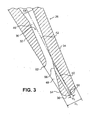
- FIG. 3 is a cross-sectional view of a portion of the airfoil, taken along line 3-3 of FIG. 2 .
- FIG. 4 is an enlarged view of a portion of the airfoil, showing region IV of FIG. 2 .
- FIG. 5 is a schematic view of the airfoil, showing cooling flow and hot gas flow.
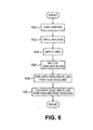
- FIG. 6 is a flow chart of a method of making and using an airfoil according to the present invention.
- the present invention relates to a fluid-cooled airfoil having a film-cooling cutback slot located along a pressure face adjacent to the trailing edge and a convective-cooling hole extending to the trailing edge.
- a cooling fluid from a plenum is metered through a metering opening, and passes to the cutback slot to provide film cooling.
- a portion of the cooling fluid delivered to the cutback slot is directed through the cooling hole extending to the trailing edge to provide convective cooling to the airfoil.
- hybrid film cooling and convective cooling is provided at or near the trailing edge, which can help maintain regions of the trailing edge of the airfoil at or below suitable thermal operating limits.
- an inlet of the hole extending to the trailing edge is located at or downstream from an upstream boundary of the cutback slot along the pressure face of the airfoil, and an outlet of the hole extending to the trailing edge is substantially aligned with a mean camber line of the airfoil.
- FIG. 1 is a schematic cross-sectional view of a gas turbine engine 10 that includes a fan section 12, a low-pressure compressor (LPC) section 14, a high-pressure compressor (HPC) section 16, a combustor section 18, a high-pressure turbine (HPT) section 20, and a low-pressure turbine (LPT) section 22.
- a centerline C L is defined by the engine 10.
- a hot section 24 of the engine 10 is generally defined from the combustor section 18 aftward, including the HPT section 20 and the LPT section 22.
- the illustrated embodiment of the gas turbine engine 10 is provided merely by way of example, and it should be recognized that the present invention applies to gas turbine engines of any configuration, such as low bypass ratio configurations. Those of ordinary skill in the art will understand the basic operation of gas turbine engines, and therefore further discussion here is unnecessary.
- FIG. 2 is a perspective view of an airfoil 26 that defines a leading edge 28, a trailing edge 30 downstream of the leading edge 28, a pressure face 32, and a suction face 34 (not visible in FIG. 2 ; see FIG. 3 ) located opposite the pressure face 32.
- the airfoil 26 is suitable for use in the hot section 24 of the gas turbine engine 10, and can be configured as either a blade or a stator.
- the airfoil 26 includes a plurality of cooling passages 36 at or near the trailing edge 30. Additional cooling openings 38 of a known configuration can optionally be provided at upstream portions of the airfoil 26.
- the cooling passages 36 are spaced apart one each other in a spanwise direction, and are located within a region defined between spanwise locations S 1 and S 2 .
- the spanwise location S 1 is at approximately 30% of a span of the airfoil 26 and the spanwise location S 2 is at approximately 70-80% of the span of the airfoil 26.
- the region defined between spanwise locations S 1 and S 2 can be selected to cover relatively high-temperature regions of the airfoil 26 near the trailing edge 30.
- limiting the region defined between spanwise locations S 1 and S 2 can help promote structural integrity of the airfoil 26 by omitting the cooling passages 36 at relatively high stress regions of the airfoil 26 (e.g., near a platform and tip).
- additional cutback slots 40 are located at the pressure face 32 adjacent to the trailing edge 30 at locations outside the region defined between spanwise locations S 1 and S 2 .
- the airfoil 26 can include a platform and a root, and in further embodiments can optionally include other features not specifically shown or described, such as a shroud.
- FIG. 3 is a cross-sectional view of a portion of the airfoil 26, taken along line 3-3 of FIG. 2 .
- a mean camber line 42 defines the mean thickness of the airfoil 26 between the pressure face 32 and the suction face 34.
- the trailing edge 30 is radiused, and has a diameter D 1 .
- a plenum 44 extends in at least partially in the spanwise direction inside the airfoil 26 for supplying a cooling fluid (e.g., bleed air).
- the plenum 44 can have a known configuration, and can act as a manifold to supply the cooling fluid to a number of cooling passages at various locations on the airfoil 26.
- Each of the cooling passages 36 (one is shown in FIG. 3 ) includes a metering opening 46, a cutback slot 48, and a trailing edge cooling hole 50.
- the metering opening 46 is fluidically connected to the plenum 44 to receive and meter cooling flows.
- the cutback slot 48 is located downstream from the metering opening 46, and is configured to deliver cooling fluid to the pressure face 32 at an outlet defined between an upstream boundary 52 and a downstream boundary 54.
- the downstream boundary 54 of the cutback slot 48 is located adjacent to and slightly upstream from the trailing edge 30.
- the cutback slot 48 is generally offset from the mean camber line 42. Additional details of the cutback slot 48 are discussed below.
- the trailing edge cooling hole 50 extends from the cutback slot 48 to the trailing edge 30, between an inlet 56 and an outlet 58.
- the inlet 56 of trailing edge cooling hole 50 is located essentially within the cutback slot 48, that is, the inlet 56 is located approximately at or downstream of the upstream boundary 52 of the cutback slot 48 and at or upstream of the downstream boundary 54.
- the outlet 58 of the trailing edge cooling hole 50 is substantially aligned with the mean camber line 42 at the trailing edge 30.
- the outlet 58 and other portions of the trailing edge cooling hole 50 has a substantially circular cross-section in the illustrated embodiment.
- the outlet 58 has a diameter (or width) D 2 .
- the diameter D 1 of the trailing edge 30 is at least approximately three times larger than the diameter D 2 of the outlet 58. Having the diameter D 1 significantly larger than the diameter D 2 helps promote structural integrity of the trailing edge 30.
- trailing edge cooling holes 50 can extend from a given cutback slot 48.
- multiple trailing edge cooling holes 50 can extend from a given cutback slot 48 at different angles relative to the centerline C L and each have separate inlets 56.
- multiple trailing edge cooling holes 50 extending from a given cutback slot 48 could share a common inlet 56.
- FIG. 4 is an enlarged view of a portion of the airfoil 26, showing region IV of FIG. 2 .
- the cutback slots 48 each have a diverging shape at their respective outlets.
- the cutback slots 48 each defme an outlet area that is substantially larger than that of either the inlet 56 or the outlet 58 of the corresponding trailing edge cooling hole 50.
- the cooling passages 36 extend substantially axially with respect to the centerline C L of the engine 10, and the trailing edge cooling holes 50 are each substantially aligned with a corresponding one of the cutback slots 48 at a given spanwise location.
- the cooling passages 36 can have different orientations as desired for particular applications.
- the cutback slot 48 and the trailing edge cooling hole 50 of any of the cooling passages 36 can extend at different angles with respect to the centerline C L .
- FIG. 5 is a schematic view of the airfoil 26, showing a cooling fluid flow 60 and hot gas flows 62.
- the hot gas flows 62 pass along the pressure face 32 and the suction face 34 of the airfoil 26, and continue past the trailing edge 30.
- the relatively cool cooling fluid flow 60 is supplied by the plenum 44 to the cooling passages 36 (only one cooling passage 36 is shown in FIG. 5 ).
- the cooling fluid flow 60 is delivered to the cutback slot 48, and a first portion 60A of the cooling fluid flow 60 is exhausted from the cutback slot 48 at the pressure face 32 of the airfoil 26 to provide film cooling at or near the trailing edge 30.
- Film cooling tends to create a layer of relatively cool fluid between the hot gas flows 62 and surfaces of the airfoil 26 in order to help keep the airfoil 26 cool.
- a second portion 60B of the cooling fluid flow 60 is delivered by the trailing edge cooling hole 50, and the second portion 60B is diverted from the cutback slot 48 and exhausted from the trailing edge 30 to provide convective cooling at or near the trailing edge 30. Convective cooling allows thermal energy from the airfoil 26 to be absorbed by the cooling fluid flow 60 and thereby removed and exhausted to the hot gas flows 62.
- the second portion 60B of the cooling fluid flow 60 also provides aerodynamic benefits by helping to straighten fluid flows at or near the trailing edge 30 of the airfoil 26. Moreover, by exhausting the second portion 60B of the cooling fluid flow 60 at the trailing edge 30 along the mean camber line 42, the relatively high mixing losses typically associated with pressure face and suction face cooling flows are avoided.
- FIG. 6 is a flow chart of a method of making and using the airfoil 26.
- the airfoil 26 is created using a casting process (step 100).
- one or more of cutback slots 48 are defined, which can be accomplished using casting cores in a known manner.
- one or more trailing edge cooling holes 50 are drilled in the airfoil 26 (step 102). Drilling can be performed using electric discharge machining (EDM), laser drilling, or other suitable processes. When multiple trailing edge cooling holes 50 are desired, they can be drilled simultaneously or sequentially.
- EDM electric discharge machining
- a thermal barrier coating is also applied to the airfoil 26 (step 104). In one embodiment, the TBC is applied subsequent to drilling of the trailing edge cooling holes.
- a cooling fluid is supplied and metered when the airfoil 26 is in operation (step 106), and the metered cooling fluid is delivered to the cutback slot 48 to provide film cooling (step 108). A portion of the cooling fluid delivered to the cutback slot 48 is diverted for delivery by the trailing edge cooling holes 50 (step 110).
Landscapes
- Engineering & Computer Science (AREA)
- Mechanical Engineering (AREA)
- General Engineering & Computer Science (AREA)
- Turbine Rotor Nozzle Sealing (AREA)
Abstract
Description
- The present invention relates to fluid-cooled airfoils, and more particularly to fluid-cooled airfoils suitable for use with gas turbine engines.
- Airfoils, such as those used in gas turbine engines, often operate in relatively hot environments. In order to help ensure air foil integrity, airfoils can utilize high temperature alloys, thermal barrier coatings, and cooling fluid delivery. However, known cooling schemes may be inadequate for some desired applications. Inadequate cooling fluid delivery can lead to spallation of coatings, and other wear or damage to the airfoil (e.g., crack formation), which may necessitate repair or replacement of the airfoil. Such a need for repair or replacement of an airfoil is costly and time-consuming. Therefore, it is desired to provide for improved fluid cooling for an airfoil, particularly at a trailing edge of the airfoil.
- An apparatus according to the present invention for use with a gas turbine engine includes an airfoil, a metering opening for metering a cooling fluid, a cutback slot configured to deliver the cooling fluid from the metering opening, and a cooling hole. The airfoil defines a trailing edge, opposite first and second faces, and a mean camber line. The cutback slot is defined along the first face of the airfoil adjacent to the trailing edge and is offset from the mean camber line of the airfoil. The cooling hole has an outlet that is located at the trailing edge and substantially aligned with the mean camber line of the airfoil. The cooling hole delivers a portion of the cooling fluid from the metering opening.
- Viewed from another aspect the invention provides an airfoil comprising a pressure face; a suction face located opposite the pressure face; a mean camber line defined midway between the pressure and suction faces; a trailing edge substantially aligned with the mean camber line; a plurality of trailing edge cooling passages spaced from one another in a spanwise direction, wherein each of the trailing edge cooling passages comprises: a first portion that defines an outlet arranged along the pressure face of the airfoil, wherein the outlet of the first portion is configured as a cutback slot to provide film cooling; and a second portion that defines an outlet at the trailing edge, the outlet of the second portion being substantially aligned with the mean camber line to provide convective cooling.
-
FIG. 1 is a schematic cross-sectional view of a gas turbine engine. -
FIG. 2 is a perspective view of an airfoil according to the present invention. -
FIG. 3 is a cross-sectional view of a portion of the airfoil, taken along line 3-3 ofFIG. 2 . -
FIG. 4 is an enlarged view of a portion of the airfoil, showing region IV ofFIG. 2 . -
FIG. 5 is a schematic view of the airfoil, showing cooling flow and hot gas flow. -
FIG. 6 is a flow chart of a method of making and using an airfoil according to the present invention. - In general, the present invention relates to a fluid-cooled airfoil having a film-cooling cutback slot located along a pressure face adjacent to the trailing edge and a convective-cooling hole extending to the trailing edge. A cooling fluid from a plenum is metered through a metering opening, and passes to the cutback slot to provide film cooling. A portion of the cooling fluid delivered to the cutback slot is directed through the cooling hole extending to the trailing edge to provide convective cooling to the airfoil. In that way, hybrid film cooling and convective cooling is provided at or near the trailing edge, which can help maintain regions of the trailing edge of the airfoil at or below suitable thermal operating limits. In one embodiment, an inlet of the hole extending to the trailing edge is located at or downstream from an upstream boundary of the cutback slot along the pressure face of the airfoil, and an outlet of the hole extending to the trailing edge is substantially aligned with a mean camber line of the airfoil.
-
FIG. 1 is a schematic cross-sectional view of agas turbine engine 10 that includes afan section 12, a low-pressure compressor (LPC)section 14, a high-pressure compressor (HPC)section 16, acombustor section 18, a high-pressure turbine (HPT)section 20, and a low-pressure turbine (LPT)section 22. A centerline CL is defined by theengine 10. Ahot section 24 of theengine 10 is generally defined from thecombustor section 18 aftward, including theHPT section 20 and theLPT section 22. The illustrated embodiment of thegas turbine engine 10 is provided merely by way of example, and it should be recognized that the present invention applies to gas turbine engines of any configuration, such as low bypass ratio configurations. Those of ordinary skill in the art will understand the basic operation of gas turbine engines, and therefore further discussion here is unnecessary. -
FIG. 2 is a perspective view of anairfoil 26 that defines a leadingedge 28, atrailing edge 30 downstream of the leadingedge 28, apressure face 32, and a suction face 34 (not visible inFIG. 2 ; seeFIG. 3 ) located opposite thepressure face 32. Theairfoil 26 is suitable for use in thehot section 24 of thegas turbine engine 10, and can be configured as either a blade or a stator. Theairfoil 26 includes a plurality ofcooling passages 36 at or near thetrailing edge 30.Additional cooling openings 38 of a known configuration can optionally be provided at upstream portions of theairfoil 26. As shown in the illustrated embodiment, thecooling passages 36 are spaced apart one each other in a spanwise direction, and are located within a region defined between spanwise locations S1 and S2. In one embodiment, the spanwise location S1 is at approximately 30% of a span of theairfoil 26 and the spanwise location S2 is at approximately 70-80% of the span of theairfoil 26. The region defined between spanwise locations S1 and S2 can be selected to cover relatively high-temperature regions of theairfoil 26 near thetrailing edge 30. Moreover, limiting the region defined between spanwise locations S1 and S2 can help promote structural integrity of theairfoil 26 by omitting thecooling passages 36 at relatively high stress regions of the airfoil 26 (e.g., near a platform and tip). As shown in the illustrated embodiment,additional cutback slots 40 are located at thepressure face 32 adjacent to thetrailing edge 30 at locations outside the region defined between spanwise locations S1 and S2. It should be noted that theairfoil 26 can include a platform and a root, and in further embodiments can optionally include other features not specifically shown or described, such as a shroud. -
FIG. 3 is a cross-sectional view of a portion of theairfoil 26, taken along line 3-3 ofFIG. 2 . As shown inFIG. 3 , amean camber line 42 defines the mean thickness of theairfoil 26 between thepressure face 32 and thesuction face 34. In the illustrated embodiment, thetrailing edge 30 is radiused, and has a diameter D1. A plenum 44 extends in at least partially in the spanwise direction inside theairfoil 26 for supplying a cooling fluid (e.g., bleed air). Theplenum 44 can have a known configuration, and can act as a manifold to supply the cooling fluid to a number of cooling passages at various locations on theairfoil 26. - Each of the cooling passages 36 (one is shown in
FIG. 3 ) includes ametering opening 46, acutback slot 48, and a trailingedge cooling hole 50. Themetering opening 46 is fluidically connected to theplenum 44 to receive and meter cooling flows. Thecutback slot 48 is located downstream from themetering opening 46, and is configured to deliver cooling fluid to thepressure face 32 at an outlet defined between anupstream boundary 52 and adownstream boundary 54. Thedownstream boundary 54 of thecutback slot 48 is located adjacent to and slightly upstream from thetrailing edge 30. Thecutback slot 48 is generally offset from themean camber line 42. Additional details of thecutback slot 48 are discussed below. - The trailing
edge cooling hole 50 extends from thecutback slot 48 to thetrailing edge 30, between aninlet 56 and anoutlet 58. In the illustrated embodiment, theinlet 56 of trailingedge cooling hole 50 is located essentially within thecutback slot 48, that is, theinlet 56 is located approximately at or downstream of theupstream boundary 52 of thecutback slot 48 and at or upstream of thedownstream boundary 54. Furthermore, in the illustrated embodiment, theoutlet 58 of the trailingedge cooling hole 50 is substantially aligned with themean camber line 42 at thetrailing edge 30. Theoutlet 58 and other portions of the trailingedge cooling hole 50 has a substantially circular cross-section in the illustrated embodiment. In alternative embodiments, other shapes of theoutlet 58 are possible, such as an elliptical or "racetrack" shape with a major axis arranged in the spanwise direction. Theoutlet 58 has a diameter (or width) D2. In one embodiment, the diameter D1 of thetrailing edge 30 is at least approximately three times larger than the diameter D2 of theoutlet 58. Having the diameter D1 significantly larger than the diameter D2 helps promote structural integrity of thetrailing edge 30. - Although in the illustrated embodiment only a single trailing
edge cooling hole 50 extends from eachcutback slot 48, in further embodiments multiple trailingedge cooling holes 50 can extend from a givencutback slot 48. For example, multiple trailingedge cooling holes 50 can extend from a givencutback slot 48 at different angles relative to the centerline CL and each haveseparate inlets 56. Alternatively, multiple trailingedge cooling holes 50 extending from a givencutback slot 48 could share acommon inlet 56. -
FIG. 4 is an enlarged view of a portion of theairfoil 26, showing region IV ofFIG. 2 . In the embodiment illustrated inFIG. 4 , thecutback slots 48 each have a diverging shape at their respective outlets. Thecutback slots 48 each defme an outlet area that is substantially larger than that of either theinlet 56 or theoutlet 58 of the corresponding trailingedge cooling hole 50. Furthermore, as shown inFIG. 4 , thecooling passages 36 extend substantially axially with respect to the centerline CL of theengine 10, and the trailingedge cooling holes 50 are each substantially aligned with a corresponding one of thecutback slots 48 at a given spanwise location. In alternative embodiments, thecooling passages 36 can have different orientations as desired for particular applications. For example, in an alternative embodiment thecutback slot 48 and the trailingedge cooling hole 50 of any of thecooling passages 36 can extend at different angles with respect to the centerline CL. -
FIG. 5 is a schematic view of theairfoil 26, showing a coolingfluid flow 60 and hot gas flows 62. During operation, the hot gas flows 62 pass along thepressure face 32 and thesuction face 34 of theairfoil 26, and continue past the trailingedge 30. The relatively cool coolingfluid flow 60 is supplied by theplenum 44 to the cooling passages 36 (only onecooling passage 36 is shown inFIG. 5 ). The coolingfluid flow 60 is delivered to thecutback slot 48, and a first portion 60A of the coolingfluid flow 60 is exhausted from thecutback slot 48 at thepressure face 32 of theairfoil 26 to provide film cooling at or near the trailingedge 30. Film cooling tends to create a layer of relatively cool fluid between the hot gas flows 62 and surfaces of theairfoil 26 in order to help keep theairfoil 26 cool. Asecond portion 60B of the coolingfluid flow 60 is delivered by the trailingedge cooling hole 50, and thesecond portion 60B is diverted from thecutback slot 48 and exhausted from the trailingedge 30 to provide convective cooling at or near the trailingedge 30. Convective cooling allows thermal energy from theairfoil 26 to be absorbed by the coolingfluid flow 60 and thereby removed and exhausted to the hot gas flows 62. - The
second portion 60B of the coolingfluid flow 60 also provides aerodynamic benefits by helping to straighten fluid flows at or near the trailingedge 30 of theairfoil 26. Moreover, by exhausting thesecond portion 60B of the coolingfluid flow 60 at the trailingedge 30 along themean camber line 42, the relatively high mixing losses typically associated with pressure face and suction face cooling flows are avoided. -
FIG. 6 is a flow chart of a method of making and using theairfoil 26. First, theairfoil 26 is created using a casting process (step 100). During casting, one or more ofcutback slots 48 are defined, which can be accomplished using casting cores in a known manner. After thecutback slots 48 are defined, one or more trailing edge cooling holes 50 are drilled in the airfoil 26 (step 102). Drilling can be performed using electric discharge machining (EDM), laser drilling, or other suitable processes. When multiple trailing edge cooling holes 50 are desired, they can be drilled simultaneously or sequentially. A thermal barrier coating (TBC) is also applied to the airfoil 26 (step 104). In one embodiment, the TBC is applied subsequent to drilling of the trailing edge cooling holes. However, with some drilling methods, such as laser drilling, the TBC could alternatively be applied prior to drilling. Furthermore, in some embodiments, use of the TBC can be omitted entirely. Lastly, for eachcooling passage 36, a cooling fluid is supplied and metered when theairfoil 26 is in operation (step 106), and the metered cooling fluid is delivered to thecutback slot 48 to provide film cooling (step 108). A portion of the cooling fluid delivered to thecutback slot 48 is diverted for delivery by the trailing edge cooling holes 50 (step 110). - While the invention has been described with reference to an exemplary embodiment(s), it will be understood by those skilled in the art that various changes may be made and equivalents may be substituted for elements thereof without departing from the scope of the invention. In addition, many modifications may be made to adapt a particular situation or material to the teachings of the invention without departing from the essential scope thereof. Therefore, it is intended that the invention not be limited to the particular embodiment(s) disclosed, but that the invention will include all embodiments falling within the scope of the appended claims. For example, the present invention can be utilized in conjunction with any number of additional cooling features, such as additional cooling passages of a known configuration. Moreover, trailing edge cooling holes can be drilled into existing airfoils with cutback slots as part of a repair or retrofit operation according to the present invention.
Claims (13)
- An apparatus for a gas turbine engine (10), the apparatus comprising:an airfoil (26) defining a trailing edge (30), opposite first (32) and second (34) faces, and a mean camber line (42) defined midway between the first and second faces;a metering opening (46) for metering a cooling fluid;a cutback slot (48) configured to deliver the cooling fluid from the metering opening, the cutback slot being defined along the first face of the airfoil adjacent to the trailing edge and offset from the mean camber line of the airfoil; anda cooling hole (50) having an outlet (58) that is located at the trailing edge and substantially aligned with the mean camber line of the airfoil, wherein the cooling hole delivers a portion of the cooling fluid from the metering opening.
- The apparatus of claim 1, and further comprising:a cooling fluid supply plenum (44) extending at least partially in a spanwise direction through an interior portion of the airfoil, the cooling fluid supply plenum being configured to supply the cooling fluid to the metering opening (46) for both the cutback slot and the cooling hole.
- The apparatus of claim 1 or 2, wherein the cutback slot (48) has a diverging shape.
- The apparatus of claim 1, 2 or 3, wherein the cutback slot (48) defines an upstream boundary (52) at the first face of the airfoil, and wherein the cooling hole defines an inlet (56) located at or downstream from the upstream boundary of the cutback slot.
- The apparatus of claim 1, 2, 3 or 4, wherein the cooling hole (50) extends in a chordwise direction.
- The apparatus of any preceding claim, wherein the trailing edge (30) is radiused.
- The apparatus of claim 6, wherein the trailing edge (30) defines a first diameter (D1) and the cooling hole defines a second diameter (D2), and wherein the first diameter is at least three times greater than the second diameter.
- The apparatus of any preceding claim, wherein the cooling hole (50) and the cutback slot (48) are substantially aligned in a spanwise direction along the airfoil.
- The apparatus of any preceding claim, wherein an outlet area of the cutback slot (48) is larger than an area of the outlet of the cooling hole (50).
- The apparatus of any preceding claim, wherein the first face (32) is a pressure face and the second face (34) is a suction face.
- An airfoil comprising an apparatus as claimed in any preceding claim and having a plurality of trailing edge cooling passages (36) spaced from one another in a spanwise direction, wherein each of the trailing edge cooling passages comprises a said cutback slot (48) and a said cooling hole (50).
- The airfoil of claim 11, wherein the plurality of trailing edge cooling passages (36) are located in a region between approximately 30% to approximately 80% of a span of the airfoil.
- A method of cooling an airfoil, comprising:delivering a cooling fluid to a cutback slot (48) at a pressure face (32) of an airfoil (26) adjacent to a trailing edge (30) of the airfoil to provide film cooling; anddelivering a portion of the cooling fluid from the cutback slot through the trailing edge (30) of the airfoil to provide convective cooling.
Applications Claiming Priority (1)
| Application Number | Priority Date | Filing Date | Title |
|---|---|---|---|
| US12/492,663 US9422816B2 (en) | 2009-06-26 | 2009-06-26 | Airfoil with hybrid drilled and cutback trailing edge |
Publications (3)
| Publication Number | Publication Date |
|---|---|
| EP2267276A2 true EP2267276A2 (en) | 2010-12-29 |
| EP2267276A3 EP2267276A3 (en) | 2014-05-21 |
| EP2267276B1 EP2267276B1 (en) | 2015-06-24 |
Family
ID=42537788
Family Applications (1)
| Application Number | Title | Priority Date | Filing Date |
|---|---|---|---|
| EP10251168.0A Active EP2267276B1 (en) | 2009-06-26 | 2010-06-28 | Airfoil with hybrid drilled and cutback trailing edge and method of cooling said airfoil |
Country Status (2)
| Country | Link |
|---|---|
| US (1) | US9422816B2 (en) |
| EP (1) | EP2267276B1 (en) |
Cited By (2)
| Publication number | Priority date | Publication date | Assignee | Title |
|---|---|---|---|---|
| EP2612994A1 (en) * | 2012-01-05 | 2013-07-10 | General Electric Company | System and method for cooling turbine blades |
| EP2867381B1 (en) | 2012-06-30 | 2021-02-17 | General Electric Company | Process for selectively producing thermal barrier coatings on turbine hardware |
Families Citing this family (9)
| Publication number | Priority date | Publication date | Assignee | Title |
|---|---|---|---|---|
| US9328617B2 (en) | 2012-03-20 | 2016-05-03 | United Technologies Corporation | Trailing edge or tip flag antiflow separation |
| US9482101B2 (en) | 2012-11-28 | 2016-11-01 | United Technologies Corporation | Trailing edge and tip cooling |
| US10436113B2 (en) | 2014-09-19 | 2019-10-08 | United Technologies Corporation | Plate for metering flow |
| US10815782B2 (en) * | 2016-06-24 | 2020-10-27 | General Electric Company | Methods for repairing airfoil trailing edges to include ejection slots therein |
| US10641103B2 (en) * | 2017-01-19 | 2020-05-05 | United Technologies Corporation | Trailing edge configuration with cast slots and drilled filmholes |
| US10539026B2 (en) | 2017-09-21 | 2020-01-21 | United Technologies Corporation | Gas turbine engine component with cooling holes having variable roughness |
| FR3108364B1 (en) * | 2020-03-18 | 2022-03-11 | Safran Aircraft Engines | Turbine blade having ribs between cooling outlets with cooling holes |
| US11519277B2 (en) * | 2021-04-15 | 2022-12-06 | General Electric Company | Component with cooling passage for a turbine engine |
| US11952912B2 (en) | 2022-08-24 | 2024-04-09 | General Electric Company | Turbine engine airfoil |
Family Cites Families (29)
| Publication number | Priority date | Publication date | Assignee | Title |
|---|---|---|---|---|
| US3246469A (en) | 1963-08-22 | 1966-04-19 | Bristol Siddelcy Engines Ltd | Cooling of aerofoil members |
| US3515499A (en) | 1968-04-22 | 1970-06-02 | Aerojet General Co | Blades and blade assemblies for turbine engines,compressors and the like |
| US4153386A (en) | 1974-12-11 | 1979-05-08 | United Technologies Corporation | Air cooled turbine vanes |
| US4601638A (en) | 1984-12-21 | 1986-07-22 | United Technologies Corporation | Airfoil trailing edge cooling arrangement |
| US5203873A (en) * | 1991-08-29 | 1993-04-20 | General Electric Company | Turbine blade impingement baffle |
| US5246340A (en) | 1991-11-19 | 1993-09-21 | Allied-Signal Inc. | Internally cooled airfoil |
| FR2689176B1 (en) | 1992-03-25 | 1995-07-13 | Snecma | DAWN REFRIGERATED FROM TURBO-MACHINE. |
| US6129515A (en) | 1992-11-20 | 2000-10-10 | United Technologies Corporation | Turbine airfoil suction aided film cooling means |
| US5368441A (en) | 1992-11-24 | 1994-11-29 | United Technologies Corporation | Turbine airfoil including diffusing trailing edge pedestals |
| US5378108A (en) | 1994-03-25 | 1995-01-03 | United Technologies Corporation | Cooled turbine blade |
| US5503529A (en) * | 1994-12-08 | 1996-04-02 | General Electric Company | Turbine blade having angled ejection slot |
| US5458461A (en) | 1994-12-12 | 1995-10-17 | General Electric Company | Film cooled slotted wall |
| EP0934455B1 (en) | 1996-10-28 | 2005-04-06 | Siemens Westinghouse Power Corporation | Airfoil for a turbomachine |
| US6102658A (en) | 1998-12-22 | 2000-08-15 | United Technologies Corporation | Trailing edge cooling apparatus for a gas turbine airfoil |
| US6126397A (en) * | 1998-12-22 | 2000-10-03 | United Technologies Corporation | Trailing edge cooling apparatus for a gas turbine airfoil |
| US6241466B1 (en) * | 1999-06-01 | 2001-06-05 | General Electric Company | Turbine airfoil breakout cooling |
| US6179565B1 (en) | 1999-08-09 | 2001-01-30 | United Technologies Corporation | Coolable airfoil structure |
| US6422819B1 (en) | 1999-12-09 | 2002-07-23 | General Electric Company | Cooled airfoil for gas turbine engine and method of making the same |
| US6325593B1 (en) * | 2000-02-18 | 2001-12-04 | General Electric Company | Ceramic turbine airfoils with cooled trailing edge blocks |
| US6520836B2 (en) * | 2001-02-28 | 2003-02-18 | General Electric Company | Method of forming a trailing edge cutback for a turbine bucket |
| US6499949B2 (en) | 2001-03-27 | 2002-12-31 | Robert Edward Schafrik | Turbine airfoil trailing edge with micro cooling channels |
| JP4798416B2 (en) | 2001-08-09 | 2011-10-19 | 株式会社Ihi | Turbine blade parts |
| US7014424B2 (en) * | 2003-04-08 | 2006-03-21 | United Technologies Corporation | Turbine element |
| GB2417295B (en) * | 2004-08-21 | 2006-10-25 | Rolls Royce Plc | A component having a cooling arrangement |
| US7374401B2 (en) * | 2005-03-01 | 2008-05-20 | General Electric Company | Bell-shaped fan cooling holes for turbine airfoil |
| US7371048B2 (en) * | 2005-05-27 | 2008-05-13 | United Technologies Corporation | Turbine blade trailing edge construction |
| GB0810986D0 (en) * | 2008-06-17 | 2008-07-23 | Rolls Royce Plc | A Cooling arrangement |
| US8079810B2 (en) * | 2008-09-16 | 2011-12-20 | Siemens Energy, Inc. | Turbine airfoil cooling system with divergent film cooling hole |
| US7985050B1 (en) | 2008-12-15 | 2011-07-26 | Florida Turbine Technologies, Inc. | Turbine blade with trailing edge cooling |
-
2009
- 2009-06-26 US US12/492,663 patent/US9422816B2/en active Active
-
2010
- 2010-06-28 EP EP10251168.0A patent/EP2267276B1/en active Active
Non-Patent Citations (1)
| Title |
|---|
| None |
Cited By (5)
| Publication number | Priority date | Publication date | Assignee | Title |
|---|---|---|---|---|
| EP2612994A1 (en) * | 2012-01-05 | 2013-07-10 | General Electric Company | System and method for cooling turbine blades |
| CN103195489A (en) * | 2012-01-05 | 2013-07-10 | 通用电气公司 | System and method for cooling turbine blades |
| US9051842B2 (en) | 2012-01-05 | 2015-06-09 | General Electric Company | System and method for cooling turbine blades |
| CN103195489B (en) * | 2012-01-05 | 2016-08-17 | 通用电气公司 | System and method for cooling turbine bucket |
| EP2867381B1 (en) | 2012-06-30 | 2021-02-17 | General Electric Company | Process for selectively producing thermal barrier coatings on turbine hardware |
Also Published As
| Publication number | Publication date |
|---|---|
| EP2267276B1 (en) | 2015-06-24 |
| US9422816B2 (en) | 2016-08-23 |
| EP2267276A3 (en) | 2014-05-21 |
| US20100329835A1 (en) | 2010-12-30 |
Similar Documents
| Publication | Publication Date | Title |
|---|---|---|
| EP2267276B1 (en) | Airfoil with hybrid drilled and cutback trailing edge and method of cooling said airfoil | |
| EP3112594B1 (en) | Hot gas path component trailing edge having near wall cooling features | |
| EP2713012B1 (en) | Gas turbine engine component | |
| EP3106617B1 (en) | Hot gas path component having cast-in features for near wall cooling | |
| EP3399145B1 (en) | Airfoil comprising a leading edge hybrid skin core cavity | |
| US20200024951A1 (en) | Component for a turbine engine with a cooling hole | |
| US20200141247A1 (en) | Component for a turbine engine with a film hole | |
| EP2564030A1 (en) | Turbine airfoil and method for thermal barrier coating | |
| EP2505787A1 (en) | Component of a gas turbine engine and corresponding gas turbine engine | |
| EP2998511B1 (en) | Cooling passage with surface features | |
| EP3495620B1 (en) | Airfoil with internal cooling passages | |
| CN115929410B (en) | Components with cooling channels for turbine engines | |
| US10808548B2 (en) | Double wall turbine gas turbine engine blade cooling configuration | |
| US11795824B2 (en) | Airfoil profile for a blade in a turbine engine | |
| EP2937514B1 (en) | Gas turbine engine turbine blade tip with coated recess | |
| EP3495618B1 (en) | Airfoil with internal cooling passages | |
| EP3495615B1 (en) | Airfoil with internal cooling passages | |
| EP3495619B1 (en) | Airfoil with internal cooling passages |
Legal Events
| Date | Code | Title | Description |
|---|---|---|---|
| PUAI | Public reference made under article 153(3) epc to a published international application that has entered the european phase |
Free format text: ORIGINAL CODE: 0009012 |
|
| AK | Designated contracting states |
Kind code of ref document: A2 Designated state(s): AL AT BE BG CH CY CZ DE DK EE ES FI FR GB GR HR HU IE IS IT LI LT LU LV MC MK MT NL NO PL PT RO SE SI SK SM TR |
|
| AX | Request for extension of the european patent |
Extension state: BA ME RS |
|
| PUAL | Search report despatched |
Free format text: ORIGINAL CODE: 0009013 |
|
| AK | Designated contracting states |
Kind code of ref document: A3 Designated state(s): AL AT BE BG CH CY CZ DE DK EE ES FI FR GB GR HR HU IE IS IT LI LT LU LV MC MK MT NL NO PL PT RO SE SI SK SM TR |
|
| AX | Request for extension of the european patent |
Extension state: BA ME RS |
|
| RIC1 | Information provided on ipc code assigned before grant |
Ipc: F01D 5/18 20060101AFI20140415BHEP |
|
| 17P | Request for examination filed |
Effective date: 20141114 |
|
| RBV | Designated contracting states (corrected) |
Designated state(s): AL AT BE BG CH CY CZ DE DK EE ES FI FR GB GR HR HU IE IS IT LI LT LU LV MC MK MT NL NO PL PT RO SE SI SK SM TR |
|
| GRAP | Despatch of communication of intention to grant a patent |
Free format text: ORIGINAL CODE: EPIDOSNIGR1 |
|
| INTG | Intention to grant announced |
Effective date: 20150209 |
|
| GRAS | Grant fee paid |
Free format text: ORIGINAL CODE: EPIDOSNIGR3 |
|
| GRAA | (expected) grant |
Free format text: ORIGINAL CODE: 0009210 |
|
| AK | Designated contracting states |
Kind code of ref document: B1 Designated state(s): AL AT BE BG CH CY CZ DE DK EE ES FI FR GB GR HR HU IE IS IT LI LT LU LV MC MK MT NL NO PL PT RO SE SI SK SM TR |
|
| REG | Reference to a national code |
Ref country code: GB Ref legal event code: FG4D |
|
| REG | Reference to a national code |
Ref country code: CH Ref legal event code: EP |
|
| REG | Reference to a national code |
Ref country code: AT Ref legal event code: REF Ref document number: 732981 Country of ref document: AT Kind code of ref document: T Effective date: 20150715 |
|
| REG | Reference to a national code |
Ref country code: IE Ref legal event code: FG4D |
|
| REG | Reference to a national code |
Ref country code: DE Ref legal event code: R096 Ref document number: 602010025395 Country of ref document: DE |
|
| PG25 | Lapsed in a contracting state [announced via postgrant information from national office to epo] |
Ref country code: LT Free format text: LAPSE BECAUSE OF FAILURE TO SUBMIT A TRANSLATION OF THE DESCRIPTION OR TO PAY THE FEE WITHIN THE PRESCRIBED TIME-LIMIT Effective date: 20150624 Ref country code: HR Free format text: LAPSE BECAUSE OF FAILURE TO SUBMIT A TRANSLATION OF THE DESCRIPTION OR TO PAY THE FEE WITHIN THE PRESCRIBED TIME-LIMIT Effective date: 20150624 Ref country code: NO Free format text: LAPSE BECAUSE OF FAILURE TO SUBMIT A TRANSLATION OF THE DESCRIPTION OR TO PAY THE FEE WITHIN THE PRESCRIBED TIME-LIMIT Effective date: 20150924 Ref country code: FI Free format text: LAPSE BECAUSE OF FAILURE TO SUBMIT A TRANSLATION OF THE DESCRIPTION OR TO PAY THE FEE WITHIN THE PRESCRIBED TIME-LIMIT Effective date: 20150624 |
|
| REG | Reference to a national code |
Ref country code: AT Ref legal event code: MK05 Ref document number: 732981 Country of ref document: AT Kind code of ref document: T Effective date: 20150624 |
|
| REG | Reference to a national code |
Ref country code: LT Ref legal event code: MG4D |
|
| PG25 | Lapsed in a contracting state [announced via postgrant information from national office to epo] |
Ref country code: BG Free format text: LAPSE BECAUSE OF FAILURE TO SUBMIT A TRANSLATION OF THE DESCRIPTION OR TO PAY THE FEE WITHIN THE PRESCRIBED TIME-LIMIT Effective date: 20150924 Ref country code: LV Free format text: LAPSE BECAUSE OF FAILURE TO SUBMIT A TRANSLATION OF THE DESCRIPTION OR TO PAY THE FEE WITHIN THE PRESCRIBED TIME-LIMIT Effective date: 20150624 Ref country code: GR Free format text: LAPSE BECAUSE OF FAILURE TO SUBMIT A TRANSLATION OF THE DESCRIPTION OR TO PAY THE FEE WITHIN THE PRESCRIBED TIME-LIMIT Effective date: 20150925 |
|
| REG | Reference to a national code |
Ref country code: NL Ref legal event code: MP Effective date: 20150624 |
|
| PG25 | Lapsed in a contracting state [announced via postgrant information from national office to epo] |
Ref country code: EE Free format text: LAPSE BECAUSE OF FAILURE TO SUBMIT A TRANSLATION OF THE DESCRIPTION OR TO PAY THE FEE WITHIN THE PRESCRIBED TIME-LIMIT Effective date: 20150624 Ref country code: IT Free format text: LAPSE BECAUSE OF FAILURE TO SUBMIT A TRANSLATION OF THE DESCRIPTION OR TO PAY THE FEE WITHIN THE PRESCRIBED TIME-LIMIT Effective date: 20150624 |
|
| REG | Reference to a national code |
Ref country code: CH Ref legal event code: PL |
|
| PG25 | Lapsed in a contracting state [announced via postgrant information from national office to epo] |
Ref country code: PT Free format text: LAPSE BECAUSE OF FAILURE TO SUBMIT A TRANSLATION OF THE DESCRIPTION OR TO PAY THE FEE WITHIN THE PRESCRIBED TIME-LIMIT Effective date: 20151026 Ref country code: PL Free format text: LAPSE BECAUSE OF FAILURE TO SUBMIT A TRANSLATION OF THE DESCRIPTION OR TO PAY THE FEE WITHIN THE PRESCRIBED TIME-LIMIT Effective date: 20150624 Ref country code: AT Free format text: LAPSE BECAUSE OF FAILURE TO SUBMIT A TRANSLATION OF THE DESCRIPTION OR TO PAY THE FEE WITHIN THE PRESCRIBED TIME-LIMIT Effective date: 20150624 Ref country code: IS Free format text: LAPSE BECAUSE OF FAILURE TO SUBMIT A TRANSLATION OF THE DESCRIPTION OR TO PAY THE FEE WITHIN THE PRESCRIBED TIME-LIMIT Effective date: 20151024 Ref country code: CZ Free format text: LAPSE BECAUSE OF FAILURE TO SUBMIT A TRANSLATION OF THE DESCRIPTION OR TO PAY THE FEE WITHIN THE PRESCRIBED TIME-LIMIT Effective date: 20150624 Ref country code: ES Free format text: LAPSE BECAUSE OF FAILURE TO SUBMIT A TRANSLATION OF THE DESCRIPTION OR TO PAY THE FEE WITHIN THE PRESCRIBED TIME-LIMIT Effective date: 20150624 Ref country code: SK Free format text: LAPSE BECAUSE OF FAILURE TO SUBMIT A TRANSLATION OF THE DESCRIPTION OR TO PAY THE FEE WITHIN THE PRESCRIBED TIME-LIMIT Effective date: 20150624 Ref country code: RO Free format text: LAPSE BECAUSE OF NON-PAYMENT OF DUE FEES Effective date: 20150624 |
|
| REG | Reference to a national code |
Ref country code: IE Ref legal event code: MM4A |
|
| REG | Reference to a national code |
Ref country code: DE Ref legal event code: R097 Ref document number: 602010025395 Country of ref document: DE |
|
| PG25 | Lapsed in a contracting state [announced via postgrant information from national office to epo] |
Ref country code: MC Free format text: LAPSE BECAUSE OF FAILURE TO SUBMIT A TRANSLATION OF THE DESCRIPTION OR TO PAY THE FEE WITHIN THE PRESCRIBED TIME-LIMIT Effective date: 20150624 |
|
| PG25 | Lapsed in a contracting state [announced via postgrant information from national office to epo] |
Ref country code: CH Free format text: LAPSE BECAUSE OF NON-PAYMENT OF DUE FEES Effective date: 20150630 Ref country code: IE Free format text: LAPSE BECAUSE OF NON-PAYMENT OF DUE FEES Effective date: 20150628 Ref country code: DK Free format text: LAPSE BECAUSE OF FAILURE TO SUBMIT A TRANSLATION OF THE DESCRIPTION OR TO PAY THE FEE WITHIN THE PRESCRIBED TIME-LIMIT Effective date: 20150624 Ref country code: LI Free format text: LAPSE BECAUSE OF NON-PAYMENT OF DUE FEES Effective date: 20150630 |
|
| PLBE | No opposition filed within time limit |
Free format text: ORIGINAL CODE: 0009261 |
|
| STAA | Information on the status of an ep patent application or granted ep patent |
Free format text: STATUS: NO OPPOSITION FILED WITHIN TIME LIMIT |
|
| 26N | No opposition filed |
Effective date: 20160329 |
|
| PG25 | Lapsed in a contracting state [announced via postgrant information from national office to epo] |
Ref country code: SI Free format text: LAPSE BECAUSE OF FAILURE TO SUBMIT A TRANSLATION OF THE DESCRIPTION OR TO PAY THE FEE WITHIN THE PRESCRIBED TIME-LIMIT Effective date: 20150624 |
|
| REG | Reference to a national code |
Ref country code: FR Ref legal event code: ST Effective date: 20160729 |
|
| PG25 | Lapsed in a contracting state [announced via postgrant information from national office to epo] |
Ref country code: FR Free format text: LAPSE BECAUSE OF NON-PAYMENT OF DUE FEES Effective date: 20150824 |
|
| PG25 | Lapsed in a contracting state [announced via postgrant information from national office to epo] |
Ref country code: MT Free format text: LAPSE BECAUSE OF FAILURE TO SUBMIT A TRANSLATION OF THE DESCRIPTION OR TO PAY THE FEE WITHIN THE PRESCRIBED TIME-LIMIT Effective date: 20150624 Ref country code: BE Free format text: LAPSE BECAUSE OF FAILURE TO SUBMIT A TRANSLATION OF THE DESCRIPTION OR TO PAY THE FEE WITHIN THE PRESCRIBED TIME-LIMIT Effective date: 20150624 |
|
| PG25 | Lapsed in a contracting state [announced via postgrant information from national office to epo] |
Ref country code: HU Free format text: LAPSE BECAUSE OF FAILURE TO SUBMIT A TRANSLATION OF THE DESCRIPTION OR TO PAY THE FEE WITHIN THE PRESCRIBED TIME-LIMIT; INVALID AB INITIO Effective date: 20100628 Ref country code: SM Free format text: LAPSE BECAUSE OF FAILURE TO SUBMIT A TRANSLATION OF THE DESCRIPTION OR TO PAY THE FEE WITHIN THE PRESCRIBED TIME-LIMIT Effective date: 20150624 |
|
| PG25 | Lapsed in a contracting state [announced via postgrant information from national office to epo] |
Ref country code: NL Free format text: LAPSE BECAUSE OF FAILURE TO SUBMIT A TRANSLATION OF THE DESCRIPTION OR TO PAY THE FEE WITHIN THE PRESCRIBED TIME-LIMIT Effective date: 20150624 Ref country code: CY Free format text: LAPSE BECAUSE OF FAILURE TO SUBMIT A TRANSLATION OF THE DESCRIPTION OR TO PAY THE FEE WITHIN THE PRESCRIBED TIME-LIMIT Effective date: 20150624 Ref country code: SE Free format text: LAPSE BECAUSE OF FAILURE TO SUBMIT A TRANSLATION OF THE DESCRIPTION OR TO PAY THE FEE WITHIN THE PRESCRIBED TIME-LIMIT Effective date: 20150624 |
|
| REG | Reference to a national code |
Ref country code: DE Ref legal event code: R082 Ref document number: 602010025395 Country of ref document: DE Representative=s name: SCHMITT-NILSON SCHRAUD WAIBEL WOHLFROM PATENTA, DE |
|
| REG | Reference to a national code |
Ref country code: DE Ref legal event code: R082 Ref document number: 602010025395 Country of ref document: DE Representative=s name: SCHMITT-NILSON SCHRAUD WAIBEL WOHLFROM PATENTA, DE Ref country code: DE Ref legal event code: R081 Ref document number: 602010025395 Country of ref document: DE Owner name: UNITED TECHNOLOGIES CORP. (N.D.GES.D. STAATES , US Free format text: FORMER OWNER: UNITED TECHNOLOGIES CORP., HARTFORD, CONN., US |
|
| PG25 | Lapsed in a contracting state [announced via postgrant information from national office to epo] |
Ref country code: TR Free format text: LAPSE BECAUSE OF FAILURE TO SUBMIT A TRANSLATION OF THE DESCRIPTION OR TO PAY THE FEE WITHIN THE PRESCRIBED TIME-LIMIT Effective date: 20150624 |
|
| PG25 | Lapsed in a contracting state [announced via postgrant information from national office to epo] |
Ref country code: LU Free format text: LAPSE BECAUSE OF NON-PAYMENT OF DUE FEES Effective date: 20150628 |
|
| PG25 | Lapsed in a contracting state [announced via postgrant information from national office to epo] |
Ref country code: MK Free format text: LAPSE BECAUSE OF FAILURE TO SUBMIT A TRANSLATION OF THE DESCRIPTION OR TO PAY THE FEE WITHIN THE PRESCRIBED TIME-LIMIT Effective date: 20150624 |
|
| PG25 | Lapsed in a contracting state [announced via postgrant information from national office to epo] |
Ref country code: AL Free format text: LAPSE BECAUSE OF FAILURE TO SUBMIT A TRANSLATION OF THE DESCRIPTION OR TO PAY THE FEE WITHIN THE PRESCRIBED TIME-LIMIT Effective date: 20150624 |
|
| REG | Reference to a national code |
Ref country code: DE Ref legal event code: R081 Ref document number: 602010025395 Country of ref document: DE Owner name: RAYTHEON TECHNOLOGIES CORPORATION (N.D.GES.D.S, US Free format text: FORMER OWNER: UNITED TECHNOLOGIES CORP. (N.D.GES.D. STAATES DELAWARE), FARMINGTON, CONN., US Ref country code: DE Ref legal event code: R081 Ref document number: 602010025395 Country of ref document: DE Owner name: RTX CORPORATION (N.D.GES.D. STAATES DELAWARE),, US Free format text: FORMER OWNER: UNITED TECHNOLOGIES CORP. (N.D.GES.D. STAATES DELAWARE), FARMINGTON, CONN., US |
|
| P01 | Opt-out of the competence of the unified patent court (upc) registered |
Effective date: 20230519 |
|
| PGFP | Annual fee paid to national office [announced via postgrant information from national office to epo] |
Ref country code: DE Payment date: 20250520 Year of fee payment: 16 |
|
| PGFP | Annual fee paid to national office [announced via postgrant information from national office to epo] |
Ref country code: GB Payment date: 20250520 Year of fee payment: 16 |
|
| REG | Reference to a national code |
Ref country code: DE Ref legal event code: R081 Ref document number: 602010025395 Country of ref document: DE Owner name: RTX CORPORATION (N.D.GES.D. STAATES DELAWARE),, US Free format text: FORMER OWNER: RAYTHEON TECHNOLOGIES CORPORATION (N.D.GES.D.STAATES DELAWARE), ARLINGTON, VA, US |