EP2267274A2 - A compressor blade - Google Patents
A compressor blade Download PDFInfo
- Publication number
- EP2267274A2 EP2267274A2 EP10165731A EP10165731A EP2267274A2 EP 2267274 A2 EP2267274 A2 EP 2267274A2 EP 10165731 A EP10165731 A EP 10165731A EP 10165731 A EP10165731 A EP 10165731A EP 2267274 A2 EP2267274 A2 EP 2267274A2
- Authority
- EP
- European Patent Office
- Prior art keywords
- blade
- slot
- suction surface
- discontinuity
- curvature
- Prior art date
- Legal status (The legal status is an assumption and is not a legal conclusion. Google has not performed a legal analysis and makes no representation as to the accuracy of the status listed.)
- Withdrawn
Links
- 239000012530 fluid Substances 0.000 claims abstract description 9
- 230000009467 reduction Effects 0.000 claims description 13
- 230000007423 decrease Effects 0.000 claims description 3
- 230000008859 change Effects 0.000 abstract description 5
- 230000035939 shock Effects 0.000 description 15
- 230000008901 benefit Effects 0.000 description 7
- 238000000926 separation method Methods 0.000 description 6
- 230000000694 effects Effects 0.000 description 3
- 238000005192 partition Methods 0.000 description 3
- 230000002411 adverse Effects 0.000 description 2
- 238000009792 diffusion process Methods 0.000 description 2
- 230000003993 interaction Effects 0.000 description 2
- 210000003127 knee Anatomy 0.000 description 2
- 230000002349 favourable effect Effects 0.000 description 1
- 238000002955 isolation Methods 0.000 description 1
- 238000012423 maintenance Methods 0.000 description 1
- 230000000116 mitigating effect Effects 0.000 description 1
- 230000002028 premature Effects 0.000 description 1
- 238000011084 recovery Methods 0.000 description 1
- 230000007704 transition Effects 0.000 description 1
- 238000011144 upstream manufacturing Methods 0.000 description 1
Images

Classifications
-
- F—MECHANICAL ENGINEERING; LIGHTING; HEATING; WEAPONS; BLASTING
- F01—MACHINES OR ENGINES IN GENERAL; ENGINE PLANTS IN GENERAL; STEAM ENGINES
- F01D—NON-POSITIVE DISPLACEMENT MACHINES OR ENGINES, e.g. STEAM TURBINES
- F01D5/00—Blades; Blade-carrying members; Heating, heat-insulating, cooling or antivibration means on the blades or the members
- F01D5/12—Blades
- F01D5/14—Form or construction
- F01D5/141—Shape, i.e. outer, aerodynamic form
- F01D5/145—Means for influencing boundary layers or secondary circulations
-
- F—MECHANICAL ENGINEERING; LIGHTING; HEATING; WEAPONS; BLASTING
- F04—POSITIVE - DISPLACEMENT MACHINES FOR LIQUIDS; PUMPS FOR LIQUIDS OR ELASTIC FLUIDS
- F04D—NON-POSITIVE-DISPLACEMENT PUMPS
- F04D29/00—Details, component parts, or accessories
- F04D29/66—Combating cavitation, whirls, noise, vibration or the like; Balancing
- F04D29/68—Combating cavitation, whirls, noise, vibration or the like; Balancing by influencing boundary layers
- F04D29/681—Combating cavitation, whirls, noise, vibration or the like; Balancing by influencing boundary layers especially adapted for elastic fluid pumps
- F04D29/682—Combating cavitation, whirls, noise, vibration or the like; Balancing by influencing boundary layers especially adapted for elastic fluid pumps by fluid extraction
-
- Y—GENERAL TAGGING OF NEW TECHNOLOGICAL DEVELOPMENTS; GENERAL TAGGING OF CROSS-SECTIONAL TECHNOLOGIES SPANNING OVER SEVERAL SECTIONS OF THE IPC; TECHNICAL SUBJECTS COVERED BY FORMER USPC CROSS-REFERENCE ART COLLECTIONS [XRACs] AND DIGESTS
- Y02—TECHNOLOGIES OR APPLICATIONS FOR MITIGATION OR ADAPTATION AGAINST CLIMATE CHANGE
- Y02T—CLIMATE CHANGE MITIGATION TECHNOLOGIES RELATED TO TRANSPORTATION
- Y02T50/00—Aeronautics or air transport
- Y02T50/60—Efficient propulsion technologies, e.g. for aircraft
Definitions
- the present invention relates to a blade for a compressor, and particularly, but not exclusively, relates to an aspirated blade for a compressor.
- the present invention therefore seeks to address this issue.
- a blade for a compressor comprising a pressure surface and a suction surface
- the suction surface comprises: a discontinuity in the chord-wise curvature of an intermediate portion of the suction surface between the blade leading edge and blade trailing edge; and a slot arranged along at least a portion of the blade in a substantially span-wise direction, the slot being disposed at or near the said discontinuity in the curvature, such that when in use, lower momentum fluid near the suction surface is aspirated into the slot.
- the blade thickness may increase monotonically from the leading edge to a point of maximum blade thickness.
- the blade thickness may decrease monotonically from the point of maximum blade thickness to the trailing edge.
- the maximum blade thickness may occur at 75% of the axial chord.
- the discontinuity in the suction surface curvature may occur aft of 50% of the axial chord.
- the discontinuity in the suction surface curvature may occur at approximately 75% of axial chord.
- the discontinuity in the suction surface curvature may occur at, or immediately downstream of, the point of maximum blade thickness.
- the discontinuity in curvature may be a finite discontinuity in curvature and may be caused by a discontinuity in one or more of the first, second or third derivatives of the suction surface profile.
- the first and second derivatives may be with respect to axial distance or may be with respect to another parameter, for example blade arc length. There may be a point of inflection at the discontinuity in curvature.
- the discontinuity in curvature may be sufficient to cause a reduction in the Mach number at the boundary layer edge.
- the reduction in the Mach number may be a sharp reduction in the Mach number.
- the reduction in the Mach number may resemble a supersonic shock-wave, albeit for subsonic Mach numbers.
- the reduction may be a sudden and sharp drop in the Mach number over a short distance, which may appear as a "knee" in the boundary layer edge Mach number profile.
- One or more internal passages may be disposed within the blade and the internal passages may be connected to the slot so as to provide a flow path within the blade for flow aspirated into the slot.
- the internal passages may be defined by passage walls and the passage walls may be adapted to guide the flow aspirated into the slot to the blade hub and/or tip.
- the passage walls may define a substantially elliptical path for the flow inside the blade.
- the total area of outlets of the internal passages may be equal to or greater than the throat area of the slot.
- a turbomachine passage comprising a hub wall, a casing wall and a blade for a compressor, the blade comprising a pressure surface and a suction surface, wherein the suction surface comprises: a discontinuity in the chord-wise curvature of an intermediate portion of the suction surface between the blade leading edge and blade trailing edge; and a slot arranged along at least a portion of the blade in a substantially span-wise direction, the slot being disposed at or near the said discontinuity in the curvature, such that when in use, lower momentum fluid near the suction surface is aspirated into the slot, wherein the passage further comprises one or more end-wall slots in one or more of the hub wall and casing wall.
- the one or more end-wall slots may be substantially parallel to the suction surface of the blade. Alternatively, the one or more end-wall slots may be substantially perpendicular to the rotational axis of the turbomachine.
- a turbomachine passage comprising a hub wall, a casing wall and a blade for a compressor, the blade comprising a pressure surface and a suction surface, wherein the suction surface comprises: a slot arranged along at least a portion of the blade in a substantially span-wise direction, wherein the passage further comprises one or more end-wall slots in one or more of the hub wall and casing wall.
- the aforementioned features enable one or more of the following advantages: increased blade loading, increased flow turning for a given blade solidity, increased incidence range and hence an increase in compressor operating range, increased blade row efficiency, reduced solidity and hence wetted area, parts count and weight, reduced total-core or primary flow loss, reduced trailing-edge mixing loss, and low bleed mass flow rate and hence low system impact
- a flow-controlled axial-compressor stator blade row is described herein.
- the principles involved, however, are also applicable to rotor blade design.
- Flow control in this case is achieved by boundary-layer suction, also known as aspiration, whereby low-momentum fluid is removed from one or more of the blade, hub and casing surfaces.
- a blade 2 according to an embodiment of the present invention comprises a suction surface 4 and a pressure surface 6.
- the blade 2 has a leading-edge 8 and a trailing-edge 10.
- the leading-edge 8 has a profile with a high initial curvature value at the leading-edge point that drops rapidly and continuously to approximately zero curvature on the suction and pressure surfaces 6, 8.
- the trailing-edge 10 has a substantially circular surface profile, although other trailing-edge profiles are possible, for example a blunt, square or sharp knife-edge profile.
- the blade 2 has a monotonically increasing thickness distribution up to a maximum value located at approximately 0.75 of axial chord from the leading edge 8 (i.e. in the region denoted by 12 in Figure 1 ). The thickness distribution of the blade 2 then monotonically decreases from this point to the trailing edge region.
- An array of blades 2 are provided in an annular cascade to form a stator or rotor blade-row (not shown).
- the blade-row is preferably adapted for a high subsonic inlet Mach number.
- the suction surface 4 is arranged such that an almost constant, high-subsonic boundary-layer edge Mach number 14 is maintained over the blade profile up to the region 12 of maximum blade thickness.
- a change in the local suction surface 4 curvature distribution in a span-wise direction is specified, such that a sharp reduction 18 or 'subsonic shock' in the suction surface boundary layer edge Mach number is attained, as shown in Figure 1 .
- the change in curvature of the suction surface is brought about by a finite discontinuity in one or more of the first, second and third derivatives. (The first, second and third derivatives may be with respect to axial distance or may be with respect to another parameter, for example blade arc length.)
- the 'subsonic shock' is a sudden change in Mach number over a short axial distance that resembles a supersonic shock, albeit for subsonic Mach numbers.
- the sharp reduction may be a sudden and sharp drop in the Mach number over a short distance, which may appear as a "knee" in the boundary layer edge Mach number profile.
- the Mach number at the boundary layer edge drops by approximately 0.32 over a distance approximately 0.055 of the axial chord.
- These numbers are representative only and the reduction in the Mach number may be smaller or greater than that shown, as may the distance over which the reduction occurs. However, a large drop in the boundary layer edge Mach number is desirable.
- the blade solidity is chosen such that the nominal exit flow angle of the blade-row is approximately attained by the time the blade-to-blade flow reaches the axial location of the 'subsonic shock'.
- an aspiration or bleed slot 20 is placed (i.e. immediately downstream of the maximum blade thickness region 12) and boundary-layer fluid is removed from the blade suction surface 4, to prevent premature flow separation due to the Mach number discontinuity.
- the bleed slot 20 and its relative geometric position on the blade 2 can be seen in Figure 2 .
- the slot 20 may be positioned such that the 'subsonic-shock' sits just above the slot 20.
- the high point of the boundary layer edge Mach number just upstream of the 'subsonic shock' may occur over a line defining the opening of the slot 20, whilst the low point just downstream of the 'subsonic shock' may occur over the a line defining the closing of the slot 20.
- the slot 20 may occur at the point at which there is a discontinuity in the suction surface curvature such that the discontinuity occurs on an imaginary surface over the slot 20 (i.e. the surface which would have been present but for the slot).
- the local suction-surface profile tangent is set such that the flow deviation from the nominal exit flow angle is minimised.
- the peak curvature of the blade camber-line is placed aft, beyond 50% of the axial chord and in particular towards the blade trailing edge. This is in contrast to a previously-proposed prescribed-velocity-distribution blade, where the peak curvature of the camber-line is typically placed well forward, i.e. before the 50% axial chord point.
- the camber-line curvature of the blades according to the present invention is virtually zero up to at least the 50% axial chord point.
- camber-line is the mean line of the blade pressure and suction surface profiles and the pressure surface 6 does not exhibit a peak in curvature, the aforementioned location of the peak in curvature applies equally to both the suction surface 4 profile and the camber-line.
- the curvature distribution of the present invention allows the extreme aft 'subsonic shock' loading to be achieved, and also has a benefit at high subsonic Mach numbers at off-design conditions, as flow separation due to shock-boundary-layer interaction at off-design incidences is postponed.
- the bleed slot 20 is a continuous opening across the span of the blade 2 and is located at or near where the suction surface 'subsonic shock' occurs.
- the bleed slot 20 has parallel walls and is inclined to form a ramped inlet through which the suction surface boundary-layer fluid is aspirated.
- the bleed slot 20 curves back on itself to discharge the aspirated flow to a plenum located within the body of the blade 2.
- the internal blade plenum is broken up into one or more chambers and in the embodiment shown in Figure 2 , four chambers 22-25 are provided.
- the chambers 22-25 are divided from one another by respective partition walls 26, 27 and 28.
- the partition walls 26-28 define elliptical chambers.
- the end-points of the ellipses do not extend through the bleed slot 20 to the blade suction surface 4, but terminate at a point just before the span-wise bleed slot 20 turns back on itself, as can be seen in Figure 2 .
- the partition walls are formed from elliptically shaped curves describing a smooth path for the aspirated fluid to flow along.
- the divisions in the internal blade plenum are chosen such that a specific slot region and associated one or more chambers target the middle third of the blade span.
- the middle two chambers 23 and 24 target the middle third of the blade span. This arrangement ensures that an even aspiration rate is maintained across the blade span.
- the internal blade chambers 22-25 discharge the aspirated flow from the interior of the blade to the hub and/or casing end-walls.
- the cross-sectional areas of the chamber exits are chosen to be equal to or greater than the throat area of the bleed slot 20.
- An advantage of the present invention is that it enables a more rectangular pressure (or indeed Mach number) profile over the blade suction surface, as is shown in Figure 1 .
- This rectangular profile allows greater loading on the blade to be achieved, which is in contrast to conventional compressor blades which have a more triangular pressure profile with the peak Mach number closest to the leading edge.
- the loading on the blade is linked to the integral of the pressure profile and a more rectangular profile enables a greater load to be achieved.
- the peak Mach number on the suction surface with the present invention may be less than that for a conventional blade, which reduces the chance of undesirable shock wave boundary layer interactions.
- the 'subsonic shock' in isolation would be likely to trigger a flow separation, which is undesirable for a compressor blade.
- the presence of the slot at, or near, the point at which the 'subsonic shock' occurs prevents this flow separation from happening.
- further advantages are brought about by the new boundary layer, which starts downstream of the slot, as this fresh boundary layer is thinner than it would be without the slot. A thinner boundary layer exhibits less drag and is less likely to separate.
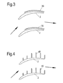
- end-wall bleed slots 30 are provided in one or more of the hub and casing end-walls within the blade passage. (NB, the blade profiles shown in Figure 3 are different from those shown in Figures 1 and 2 .)
- the end-wall bleed slots 30 are approximately 2.5% of the true blade chord in width.
- the end-wall bleed slots 30 run approximately 2.5% of the true blade chord above the blade suction surface 4 along the hub and/or casing end-wall, such that the end-wall bleed slots 30 follow the suction surface 4 over a substantial portion of the blade profile.
- the length of the slot may be from the suction-surface pressure peak to the suction surface trailing edge 10.
- end-wall bleed slots 40 are provided in one or more of the hub and casing end-walls within the blade passage.
- the end-wall bleed slots 40 comprise one or more circumferential slots that extend from a point near or at the interface between the blade suction surface 4 and the hub or casing end-wall.
- the end-wall bleed slots 40 can have varying circumferential lengths, but for simplicity can be arranged with an approximately constant length of typically 20% of the blade pitch.
- a number of the end-wall bleed slots 40 for example 5 to 10, are spaced equally along the hub and/or casing end-wall, beginning at the blade suction surface pressure peak and are distributed along the end-wall up to the suction surface trailing edge 10.
- the end-wall bleed slots 30, 40 are used to militate against the adverse effects of the over-turning end-wall boundary layer. By removing the end-wall boundary layer, the end-wall corner separations that result in significant entropy generation and blockage can be reduced or eliminated.
- the manner in which flow diffusion is achieved via a subsonic shock and the application of aspiration control to the blade profile provides a new type of ultra-highly loaded, low-loss stator/rotor blade with low blade solidity.
- the end-wall slots and the resulting end-wall aspiration separately from, or in conjunction with, the blade slots provide an ultra-highly loaded, low-loss stator/rotor blade concept.
Landscapes
- Engineering & Computer Science (AREA)
- Mechanical Engineering (AREA)
- General Engineering & Computer Science (AREA)
- Physics & Mathematics (AREA)
- Fluid Mechanics (AREA)
- Structures Of Non-Positive Displacement Pumps (AREA)
Abstract
Description
- The present invention relates to a blade for a compressor, and particularly, but not exclusively, relates to an aspirated blade for a compressor.
- The application of flow control to axial-compressor blade/vane row design allows an increase in blade/vane loading levels and a broadened operating range. In particular, the increase in loading of blade/vane rows results in fewer blades/vanes and/or stages used for the same magnitude of flow turning and compressor pressure ratio respectively. The reduction in parts-count obtained yields a reduction in wetted area, reduced maintenance and reduced total weight of the compressor.
- To this end, it is known to provide flow control with a slot on the suction surface of a compressor blade to delay flow separation, see for example
W02007/106059 . However, such bleed slots remove mainstream flow, which affects the overall efficiency of a jet engine or gas turbine. (Generally speaking, the higher the pressure ratio the more efficient the engine, and if less of the mass-flow is experiencing this high pressure ratio, because it is being bled off, this will adversely affect the overall efficiency.) - The present invention therefore seeks to address this issue.
- According to a first aspect of the present invention there is provided a blade for a compressor comprising a pressure surface and a suction surface, wherein the suction surface comprises: a discontinuity in the chord-wise curvature of an intermediate portion of the suction surface between the blade leading edge and blade trailing edge; and a slot arranged along at least a portion of the blade in a substantially span-wise direction, the slot being disposed at or near the said discontinuity in the curvature, such that when in use, lower momentum fluid near the suction surface is aspirated into the slot.
- The blade thickness may increase monotonically from the leading edge to a point of maximum blade thickness. The blade thickness may decrease monotonically from the point of maximum blade thickness to the trailing edge. The maximum blade thickness may occur at 75% of the axial chord.
- The discontinuity in the suction surface curvature may occur aft of 50% of the axial chord. The discontinuity in the suction surface curvature may occur at approximately 75% of axial chord. The discontinuity in the suction surface curvature may occur at, or immediately downstream of, the point of maximum blade thickness.
- The discontinuity in curvature may be a finite discontinuity in curvature and may be caused by a discontinuity in one or more of the first, second or third derivatives of the suction surface profile. The first and second derivatives may be with respect to axial distance or may be with respect to another parameter, for example blade arc length. There may be a point of inflection at the discontinuity in curvature.
- When in use, the discontinuity in curvature may be sufficient to cause a reduction in the Mach number at the boundary layer edge. The reduction in the Mach number may be a sharp reduction in the Mach number. The reduction in the Mach number may resemble a supersonic shock-wave, albeit for subsonic Mach numbers. In other words, the reduction may be a sudden and sharp drop in the Mach number over a short distance, which may appear as a "knee" in the boundary layer edge Mach number profile.
- One or more internal passages may be disposed within the blade and the internal passages may be connected to the slot so as to provide a flow path within the blade for flow aspirated into the slot. The internal passages may be defined by passage walls and the passage walls may be adapted to guide the flow aspirated into the slot to the blade hub and/or tip.
- The passage walls may define a substantially elliptical path for the flow inside the blade. The total area of outlets of the internal passages may be equal to or greater than the throat area of the slot.
- According to a second aspect of the invention there is provided a turbomachine passage comprising a hub wall, a casing wall and a blade for a compressor, the blade comprising a pressure surface and a suction surface, wherein the suction surface comprises: a discontinuity in the chord-wise curvature of an intermediate portion of the suction surface between the blade leading edge and blade trailing edge; and a slot arranged along at least a portion of the blade in a substantially span-wise direction, the slot being disposed at or near the said discontinuity in the curvature, such that when in use, lower momentum fluid near the suction surface is aspirated into the slot, wherein the passage further comprises one or more end-wall slots in one or more of the hub wall and casing wall.
- The one or more end-wall slots may be substantially parallel to the suction surface of the blade. Alternatively, the one or more end-wall slots may be substantially perpendicular to the rotational axis of the turbomachine.
- According to a third aspect of the invention there is provided a turbomachine passage comprising a hub wall, a casing wall and a blade for a compressor, the blade comprising a pressure surface and a suction surface, wherein the suction surface comprises: a slot arranged along at least a portion of the blade in a substantially span-wise direction, wherein the passage further comprises one or more end-wall slots in one or more of the hub wall and casing wall.
- The aforementioned features enable one or more of the following advantages: increased blade loading, increased flow turning for a given blade solidity, increased incidence range and hence an increase in compressor operating range, increased blade row efficiency, reduced solidity and hence wetted area, parts count and weight, reduced total-core or primary flow loss, reduced trailing-edge mixing loss, and low bleed mass flow rate and hence low system impact
- For a better understanding of the present invention, and to show more clearly how it may be carried into effect, reference will now be made, by way of example, to the accompanying drawings, in which:-
-
Figure 1 shows a blade profile according to an embodiment of the present invention andFigure 1 also shows the corresponding flow Mach numbers at the boundary layer edge on both the suction and pressure surfaces; -
Figure 2 shows a perspective view of a blade according to an embodiment of the present invention; -
Figure 3 shows a plan view of a blade row with end-wall slots according to a first example of the present invention; and -
Figure 4 shows a plan view of a blade row with end-wall slots according to a second example of the present invention. - A flow-controlled axial-compressor stator blade row is described herein. The principles involved, however, are also applicable to rotor blade design. Flow control in this case is achieved by boundary-layer suction, also known as aspiration, whereby low-momentum fluid is removed from one or more of the blade, hub and casing surfaces.
- With reference to
Figure 1 , ablade 2 according to an embodiment of the present invention comprises a suction surface 4 and apressure surface 6. Theblade 2 has a leading-edge 8 and a trailing-edge 10. The leading-edge 8 has a profile with a high initial curvature value at the leading-edge point that drops rapidly and continuously to approximately zero curvature on the suction andpressure surfaces edge 10 has a substantially circular surface profile, although other trailing-edge profiles are possible, for example a blunt, square or sharp knife-edge profile. - The
blade 2 has a monotonically increasing thickness distribution up to a maximum value located at approximately 0.75 of axial chord from the leading edge 8 (i.e. in the region denoted by 12 inFigure 1 ). The thickness distribution of theblade 2 then monotonically decreases from this point to the trailing edge region. - An array of
blades 2 are provided in an annular cascade to form a stator or rotor blade-row (not shown). - The blade-row is preferably adapted for a high subsonic inlet Mach number. As is shown in
Figure 1 , the suction surface 4 is arranged such that an almost constant, high-subsonic boundary-layeredge Mach number 14 is maintained over the blade profile up to theregion 12 of maximum blade thickness. Immediately downstream of the maximumblade thickness region 12, a change in the local suction surface 4 curvature distribution in a span-wise direction is specified, such that asharp reduction 18 or 'subsonic shock' in the suction surface boundary layer edge Mach number is attained, as shown inFigure 1 . The change in curvature of the suction surface is brought about by a finite discontinuity in one or more of the first, second and third derivatives. (The first, second and third derivatives may be with respect to axial distance or may be with respect to another parameter, for example blade arc length.) - Here, the 'subsonic shock' is a sudden change in Mach number over a short axial distance that resembles a supersonic shock, albeit for subsonic Mach numbers. In other words, the sharp reduction may be a sudden and sharp drop in the Mach number over a short distance, which may appear as a "knee" in the boundary layer edge Mach number profile.
- In the particular example, shown in
Figure 1 , the Mach number at the boundary layer edge drops by approximately 0.32 over a distance approximately 0.055 of the axial chord. These numbers are representative only and the reduction in the Mach number may be smaller or greater than that shown, as may the distance over which the reduction occurs. However, a large drop in the boundary layer edge Mach number is desirable. - The blade solidity is chosen such that the nominal exit flow angle of the blade-row is approximately attained by the time the blade-to-blade flow reaches the axial location of the 'subsonic shock'.
- With reference to
Figure 2 , at the point of the 'subsonic shock', an aspiration orbleed slot 20 is placed (i.e. immediately downstream of the maximum blade thickness region 12) and boundary-layer fluid is removed from the blade suction surface 4, to prevent premature flow separation due to the Mach number discontinuity. Thebleed slot 20 and its relative geometric position on theblade 2 can be seen inFigure 2 . - The
slot 20 may be positioned such that the 'subsonic-shock' sits just above theslot 20. In other words, the high point of the boundary layer edge Mach number just upstream of the 'subsonic shock' may occur over a line defining the opening of theslot 20, whilst the low point just downstream of the 'subsonic shock' may occur over the a line defining the closing of theslot 20. In addition, theslot 20 may occur at the point at which there is a discontinuity in the suction surface curvature such that the discontinuity occurs on an imaginary surface over the slot 20 (i.e. the surface which would have been present but for the slot). In other words there is a change in curvature between the opening of theslot 20 and the closing of theslot 20, which could not otherwise be attributed to a smooth transition in the surface curvature (i.e. there has been a discontinuity in the first, second or third derivatives at some point over the slot). - Downstream of the
bleed slot 20, the local suction-surface profile tangent is set such that the flow deviation from the nominal exit flow angle is minimised. - According to the present invention, the peak curvature of the blade camber-line is placed aft, beyond 50% of the axial chord and in particular towards the blade trailing edge. This is in contrast to a previously-proposed prescribed-velocity-distribution blade, where the peak curvature of the camber-line is typically placed well forward, i.e. before the 50% axial chord point. By contrast, the camber-line curvature of the blades according to the present invention is virtually zero up to at least the 50% axial chord point. (As the camber-line is the mean line of the blade pressure and suction surface profiles and the
pressure surface 6 does not exhibit a peak in curvature, the aforementioned location of the peak in curvature applies equally to both the suction surface 4 profile and the camber-line.) - The curvature distribution of the present invention allows the extreme aft 'subsonic shock' loading to be achieved, and also has a benefit at high subsonic Mach numbers at off-design conditions, as flow separation due to shock-boundary-layer interaction at off-design incidences is postponed.
- The
bleed slot 20 is a continuous opening across the span of theblade 2 and is located at or near where the suction surface 'subsonic shock' occurs. Thebleed slot 20 has parallel walls and is inclined to form a ramped inlet through which the suction surface boundary-layer fluid is aspirated. Within the body of theblade 2, thebleed slot 20 curves back on itself to discharge the aspirated flow to a plenum located within the body of theblade 2. - The internal blade plenum is broken up into one or more chambers and in the embodiment shown in
Figure 2 , four chambers 22-25 are provided. The chambers 22-25 are divided from one another byrespective partition walls bleed slot 20 to the blade suction surface 4, but terminate at a point just before thespan-wise bleed slot 20 turns back on itself, as can be seen inFigure 2 . The partition walls are formed from elliptically shaped curves describing a smooth path for the aspirated fluid to flow along. - The divisions in the internal blade plenum are chosen such that a specific slot region and associated one or more chambers target the middle third of the blade span. In the particular embodiment shown in
Figure 2 , the middle twochambers bleed slot 20. - An advantage of the present invention is that it enables a more rectangular pressure (or indeed Mach number) profile over the blade suction surface, as is shown in
Figure 1 . This rectangular profile allows greater loading on the blade to be achieved, which is in contrast to conventional compressor blades which have a more triangular pressure profile with the peak Mach number closest to the leading edge. The loading on the blade is linked to the integral of the pressure profile and a more rectangular profile enables a greater load to be achieved. Alternatively (or in addition), the peak Mach number on the suction surface with the present invention may be less than that for a conventional blade, which reduces the chance of undesirable shock wave boundary layer interactions. These advantages are made possible by the 'subsonic shock', which in effect localises the pressure recovery and enables the aforementioned rectangular profile. This in turn enables a higher loading and/or more turning. - Furthermore, the 'subsonic shock' in isolation would be likely to trigger a flow separation, which is undesirable for a compressor blade. However, the presence of the slot at, or near, the point at which the 'subsonic shock' occurs prevents this flow separation from happening. In addition, further advantages are brought about by the new boundary layer, which starts downstream of the slot, as this fresh boundary layer is thinner than it would be without the slot. A thinner boundary layer exhibits less drag and is less likely to separate.
- Overall, by removing the low-momentum blade boundary layer fluid that limits flow diffusion, significant increases in loading and hence flow turning are possible. The position of the
bleed slot 20 and the presence of the 'sub-sonic shock' allows a reduction of the flow into thebleed slot 20, thereby providing the advantages of an aspirated blade, whilst mitigating against the overall efficiency loss. - With reference to
Figure 3 , end-wall bleed slots 30 according to a first configuration are provided in one or more of the hub and casing end-walls within the blade passage. (NB, the blade profiles shown inFigure 3 are different from those shown inFigures 1 and 2 .) The end-wall bleed slots 30 are approximately 2.5% of the true blade chord in width. The end-wall bleed slots 30 run approximately 2.5% of the true blade chord above the blade suction surface 4 along the hub and/or casing end-wall, such that the end-wall bleed slots 30 follow the suction surface 4 over a substantial portion of the blade profile. In particular, the length of the slot may be from the suction-surface pressure peak to the suctionsurface trailing edge 10. - With reference to
Figure 4 , end-wall bleed slots 40 according to a second configuration are provided in one or more of the hub and casing end-walls within the blade passage. (NB, the blade profiles shown inFigure 4 are different from those shown inFigures 1 and 2 .) The end-wall bleed slots 40 comprise one or more circumferential slots that extend from a point near or at the interface between the blade suction surface 4 and the hub or casing end-wall. The end-wall bleed slots 40 can have varying circumferential lengths, but for simplicity can be arranged with an approximately constant length of typically 20% of the blade pitch. A number of the end-wall bleed slots 40, for example 5 to 10, are spaced equally along the hub and/or casing end-wall, beginning at the blade suction surface pressure peak and are distributed along the end-wall up to the suctionsurface trailing edge 10. - The end-
wall bleed slots - If the amount of bleed mass flow used to affect control of the flow is small, the system impact of this control is expected to be small and may even be positive. The benefits of a successful flow-control application to axial-compressor design are therefore significant, yielding more compact axial-compressor designs with higher efficiency and reduced parts-count and weight, with a favourable impact on engine cycle performance.
- According to the present invention, the manner in which flow diffusion is achieved via a subsonic shock and the application of aspiration control to the blade profile provides a new type of ultra-highly loaded, low-loss stator/rotor blade with low blade solidity. In addition, the end-wall slots and the resulting end-wall aspiration separately from, or in conjunction with, the blade slots, provide an ultra-highly loaded, low-loss stator/rotor blade concept.
Claims (15)
- A blade for a compressor comprising a pressure surface (6) and a suction surface (4), wherein the suction surface comprises:a discontinuity (18) in the chord-wise curvature of an intermediate portion of the suction surface between the blade leading edge and blade trailing edge; anda slot (20) arranged along at least a portion of the blade in a substantially span-wise direction, the slot being disposed at or near the said discontinuity in the curvature, such that when in use, lower momentum fluid near the suction surface is aspirated into the slot.
- A blade according to claim 1, wherein the blade thickness increases monotonically from the leading edge (8) to a point (12) of maximum blade thickness.
- A blade according to claim 1 or 2, wherein the blade thickness decreases monotonically from a point of maximum blade thickness to the trailing edge (10).
- A blade according to any preceding claim, wherein the maximum blade thickness occurs at 75% of the axial chord.
- A blade according to any preceding claim, wherein the discontinuity in the suction surface curvature occurs aft of 50% of the axial chord.
- A blade according to any preceding claim, wherein the discontinuity in the suction surface curvature occurs at approximately 75% of axial chord.
- A blade according to any preceding claim, wherein the discontinuity in curvature is caused by a discontinuity in one or more of the first and second derivatives of the suction surface profile.
- A blade according to any of claims 2 to 7, wherein the discontinuity in curvature occurs at, or immediately downstream of, the point of maximum blade thickness.
- A blade according to any preceding claim, wherein, when in use, the discontinuity in curvature is sufficient to cause a reduction in the Mach number at the boundary layer edge.
- A blade according to any preceding claim, wherein one or more internal passages (22, 23, 24, 25) are disposed within the blade, the internal passages being connected to the slot so as to provide a flow path within the blade for flow aspirated into the slot.
- A blade according to claim 10, wherein the internal passages are defined by passage walls (26, 27, 28), the passage walls being adapted to guide the flow aspirated into the slot to the blade hub and/or tip.
- A blade according to claim 10 or claim 11, wherein the total area of outlets of the internal passages is equal to or greater than the throat area of the slot.
- A turbomachine passage comprising a hub wall, a casing wall and the blade of any preceding claim, wherein the passage further comprises one or more end-wall slots in one or more of the hub wall and casing wall.
- A turbomachine passage as claimed in claim 13, wherein the one or more end-wall slots are substantially parallel to the suction surface of the blade.
- A turbomachine having a blade as claimed in any one of claims 1 to 12.
Applications Claiming Priority (1)
| Application Number | Priority Date | Filing Date | Title |
|---|---|---|---|
| GBGB0910647.7A GB0910647D0 (en) | 2009-06-22 | 2009-06-22 | A compressor blade |
Publications (2)
| Publication Number | Publication Date |
|---|---|
| EP2267274A2 true EP2267274A2 (en) | 2010-12-29 |
| EP2267274A3 EP2267274A3 (en) | 2017-09-27 |
Family
ID=40972483
Family Applications (1)
| Application Number | Title | Priority Date | Filing Date |
|---|---|---|---|
| EP10165731.0A Withdrawn EP2267274A3 (en) | 2009-06-22 | 2010-06-11 | A compressor blade |
Country Status (3)
| Country | Link |
|---|---|
| US (1) | US8573946B2 (en) |
| EP (1) | EP2267274A3 (en) |
| GB (1) | GB0910647D0 (en) |
Cited By (5)
| Publication number | Priority date | Publication date | Assignee | Title |
|---|---|---|---|---|
| EP3115619A1 (en) * | 2015-07-07 | 2017-01-11 | United Technologies Corporation | Compressor endwall boundary layer removal |
| EP3263837A1 (en) * | 2016-06-29 | 2018-01-03 | Rolls-Royce Corporation | Pressure recovery axial-compressor blading |
| CN107762973A (en) * | 2017-10-20 | 2018-03-06 | 哈尔滨工程大学 | Steady blade and its trailing edge groove forming method are expanded in a kind of compressor angular region |
| US10760427B2 (en) | 2017-06-23 | 2020-09-01 | Rolls-Royce Plc | Secondary flow control |
| WO2021016146A1 (en) * | 2019-07-22 | 2021-01-28 | Carrier Corporation | Centrifugal or mixed-flow compressor including aspirated diffuser |
Families Citing this family (12)
| Publication number | Priority date | Publication date | Assignee | Title |
|---|---|---|---|---|
| US10309236B2 (en) | 2013-03-14 | 2019-06-04 | Rolls-Royce Corporation | Subsonic shock strut |
| US10823194B2 (en) | 2014-12-01 | 2020-11-03 | General Electric Company | Compressor end-wall treatment with multiple flow axes |
| US10047620B2 (en) | 2014-12-16 | 2018-08-14 | General Electric Company | Circumferentially varying axial compressor endwall treatment for controlling leakage flow therein |
| US10914318B2 (en) | 2019-01-10 | 2021-02-09 | General Electric Company | Engine casing treatment for reducing circumferentially variable distortion |
| IT202000005146A1 (en) | 2020-03-11 | 2021-09-11 | Ge Avio Srl | TURBINE ENGINE WITH AERODYNAMIC PROFILE HAVING HIGH ACCELERATION AND LOW VANE CURVE |
| CN113153815B (en) * | 2020-11-22 | 2022-11-29 | 西北工业大学 | Supersonic adsorption type compressor blade based on multiple holes |
| US12071889B2 (en) | 2022-04-05 | 2024-08-27 | General Electric Company | Counter-rotating turbine |
| US12497917B2 (en) | 2022-05-18 | 2025-12-16 | General Electric Company | Counter-rotating turbine |
| US12326118B2 (en) | 2022-09-16 | 2025-06-10 | General Electric Company | Gas turbine engines with a fuel cell assembly |
| US12560094B2 (en) | 2022-10-05 | 2026-02-24 | Rtx Corporation | Axial compressor stator |
| CN117733496A (en) * | 2023-11-15 | 2024-03-22 | 南京航空航天大学 | Blade slotting mode based on spatial-temporal evolution of wall vortex of suction surface of compressor blade |
| CN117932821B (en) * | 2024-02-22 | 2024-12-06 | 北京航空航天大学 | A design method for slotting the tip of jet-enhanced blades |
Citations (2)
| Publication number | Priority date | Publication date | Assignee | Title |
|---|---|---|---|---|
| US2859910A (en) * | 1954-03-29 | 1958-11-11 | Edward A Stalker | Stators for axial flow compressors |
| WO2007106059A2 (en) | 2006-02-15 | 2007-09-20 | United Technologies Corporation | Tip turbine engine with aspirated compressor |
Family Cites Families (8)
| Publication number | Priority date | Publication date | Assignee | Title |
|---|---|---|---|---|
| FR2248732A5 (en) | 1973-10-23 | 1975-05-16 | Onera (Off Nat Aerospatiale) | |
| US5480284A (en) * | 1993-12-20 | 1996-01-02 | General Electric Company | Self bleeding rotor blade |
| US5904470A (en) * | 1997-01-13 | 1999-05-18 | Massachusetts Institute Of Technology | Counter-rotating compressors with control of boundary layers by fluid removal |
| WO1998030802A1 (en) | 1997-01-13 | 1998-07-16 | Massachusetts Institute Of Technology | Enhancement of turbomachines and compressors by fluid removal |
| US6379110B1 (en) * | 1999-02-25 | 2002-04-30 | United Technologies Corporation | Passively driven acoustic jet controlling boundary layers |
| US7320575B2 (en) | 2004-09-28 | 2008-01-22 | General Electric Company | Methods and apparatus for aerodynamically self-enhancing rotor blades |
| WO2007119696A1 (en) | 2006-04-17 | 2007-10-25 | Ihi Corporation | Blade |
| US20090016871A1 (en) | 2007-07-10 | 2009-01-15 | United Technologies Corp. | Systems and Methods Involving Variable Vanes |
-
2009
- 2009-06-22 GB GBGB0910647.7A patent/GB0910647D0/en not_active Ceased
-
2010
- 2010-06-11 EP EP10165731.0A patent/EP2267274A3/en not_active Withdrawn
- 2010-06-14 US US12/814,666 patent/US8573946B2/en not_active Expired - Fee Related
Patent Citations (2)
| Publication number | Priority date | Publication date | Assignee | Title |
|---|---|---|---|---|
| US2859910A (en) * | 1954-03-29 | 1958-11-11 | Edward A Stalker | Stators for axial flow compressors |
| WO2007106059A2 (en) | 2006-02-15 | 2007-09-20 | United Technologies Corporation | Tip turbine engine with aspirated compressor |
Cited By (8)
| Publication number | Priority date | Publication date | Assignee | Title |
|---|---|---|---|---|
| EP3115619A1 (en) * | 2015-07-07 | 2017-01-11 | United Technologies Corporation | Compressor endwall boundary layer removal |
| EP3263837A1 (en) * | 2016-06-29 | 2018-01-03 | Rolls-Royce Corporation | Pressure recovery axial-compressor blading |
| US10935041B2 (en) | 2016-06-29 | 2021-03-02 | Rolls-Royce Corporation | Pressure recovery axial-compressor blading |
| US10760427B2 (en) | 2017-06-23 | 2020-09-01 | Rolls-Royce Plc | Secondary flow control |
| CN107762973A (en) * | 2017-10-20 | 2018-03-06 | 哈尔滨工程大学 | Steady blade and its trailing edge groove forming method are expanded in a kind of compressor angular region |
| CN107762973B (en) * | 2017-10-20 | 2020-06-16 | 哈尔滨工程大学 | Compressor corner region stability-expanding blade and trailing edge groove forming method thereof |
| WO2021016146A1 (en) * | 2019-07-22 | 2021-01-28 | Carrier Corporation | Centrifugal or mixed-flow compressor including aspirated diffuser |
| CN112955661A (en) * | 2019-07-22 | 2021-06-11 | 开利公司 | Centrifugal or mixed flow compressor comprising a suction diffuser |
Also Published As
| Publication number | Publication date |
|---|---|
| GB0910647D0 (en) | 2009-08-05 |
| US20100322777A1 (en) | 2010-12-23 |
| EP2267274A3 (en) | 2017-09-27 |
| US8573946B2 (en) | 2013-11-05 |
Similar Documents
| Publication | Publication Date | Title |
|---|---|---|
| US8573946B2 (en) | Compressor blade | |
| EP1939399B1 (en) | Axial flow turbine assembly | |
| EP2376745B1 (en) | Turbine blade with banked platform | |
| EP1930600B1 (en) | Advanced booster stator vane | |
| EP1930598A2 (en) | Advanced booster rotor blade | |
| EP1930599A2 (en) | Advanced booster system | |
| JP5342637B2 (en) | Airfoil for an axial compressor that enables low loss in the low Reynolds number region | |
| GB2481822A (en) | Rotor blade with air flow passages | |
| JP2011508148A (en) | Compressor tip clearance control system including plasma actuator, compressor, and gas turbine engine including the control system | |
| US9004859B2 (en) | Turbomachine comprising an annular casing and a bladed rotor | |
| JP2011508149A (en) | Plasma compressor | |
| JP6194960B2 (en) | Axial turbomachine blade structure and gas turbine engine | |
| EP3485146B1 (en) | Turbofan engine and corresponding method of operating | |
| EP2472061B1 (en) | Gas turbine engine airfoil shaped component | |
| US20170298742A1 (en) | Turbine engine airfoil bleed pumping | |
| US20140174052A1 (en) | Exhaust diffuser and method for manufacturing an exhaust diffuser | |
| EP3653513A1 (en) | Boundary layer ingestion fan system | |
| CN111075760A (en) | Fluid wing | |
| US20140234095A1 (en) | Aerofoil for axial-flow machine | |
| EP2971576B1 (en) | Fan exit guide vane platform contouring | |
| US20180195528A1 (en) | Fluid diodes with ridges to control boundary layer in axial compressor stator vane | |
| US10495095B2 (en) | Multistage compressor with aerofoil portion profiled in a spanwise direction | |
| EP2971614B1 (en) | A subsonic shock strut | |
| Roy et al. | Experimental study of boundary layer control through tip injection on straight and swept compressor blades | |
| EP2818637B1 (en) | Gas turbine component for releasing a coolant flow into an environment subject to periodic fluctuations in pressure |
Legal Events
| Date | Code | Title | Description |
|---|---|---|---|
| PUAI | Public reference made under article 153(3) epc to a published international application that has entered the european phase |
Free format text: ORIGINAL CODE: 0009012 |
|
| AK | Designated contracting states |
Kind code of ref document: A2 Designated state(s): AL AT BE BG CH CY CZ DE DK EE ES FI FR GB GR HR HU IE IS IT LI LT LU LV MC MK MT NL NO PL PT RO SE SI SK SM TR |
|
| AX | Request for extension of the european patent |
Extension state: BA ME RS |
|
| RAP1 | Party data changed (applicant data changed or rights of an application transferred) |
Owner name: ROLLS-ROYCE PLC |
|
| PUAL | Search report despatched |
Free format text: ORIGINAL CODE: 0009013 |
|
| AK | Designated contracting states |
Kind code of ref document: A3 Designated state(s): AL AT BE BG CH CY CZ DE DK EE ES FI FR GB GR HR HU IE IS IT LI LT LU LV MC MK MT NL NO PL PT RO SE SI SK SM TR |
|
| AX | Request for extension of the european patent |
Extension state: BA ME RS |
|
| RIC1 | Information provided on ipc code assigned before grant |
Ipc: F01D 5/14 20060101AFI20170823BHEP |
|
| STAA | Information on the status of an ep patent application or granted ep patent |
Free format text: STATUS: REQUEST FOR EXAMINATION WAS MADE |
|
| 17P | Request for examination filed |
Effective date: 20180227 |
|
| RBV | Designated contracting states (corrected) |
Designated state(s): AL AT BE BG CH CY CZ DE DK EE ES FI FR GB GR HR HU IE IS IT LI LT LU LV MC MK MT NL NO PL PT RO SE SI SK SM TR |
|
| STAA | Information on the status of an ep patent application or granted ep patent |
Free format text: STATUS: EXAMINATION IS IN PROGRESS |
|
| 17Q | First examination report despatched |
Effective date: 20180604 |
|
| STAA | Information on the status of an ep patent application or granted ep patent |
Free format text: STATUS: THE APPLICATION IS DEEMED TO BE WITHDRAWN |
|
| 18D | Application deemed to be withdrawn |
Effective date: 20181016 |