EP2266879A1 - Assisted in-flight refuelling system - Google Patents
Assisted in-flight refuelling system Download PDFInfo
- Publication number
- EP2266879A1 EP2266879A1 EP10164829A EP10164829A EP2266879A1 EP 2266879 A1 EP2266879 A1 EP 2266879A1 EP 10164829 A EP10164829 A EP 10164829A EP 10164829 A EP10164829 A EP 10164829A EP 2266879 A1 EP2266879 A1 EP 2266879A1
- Authority
- EP
- European Patent Office
- Prior art keywords
- aircraft
- drogue
- take
- distance
- assisted
- Prior art date
- Legal status (The legal status is an assumption and is not a legal conclusion. Google has not performed a legal analysis and makes no representation as to the accuracy of the status listed.)
- Granted
Links
Images




Classifications
-
- B—PERFORMING OPERATIONS; TRANSPORTING
- B64—AIRCRAFT; AVIATION; COSMONAUTICS
- B64D—EQUIPMENT FOR FITTING IN OR TO AIRCRAFT; FLIGHT SUITS; PARACHUTES; ARRANGEMENT OR MOUNTING OF POWER PLANTS OR PROPULSION TRANSMISSIONS IN AIRCRAFT
- B64D39/00—Refuelling during flight
- B64D39/06—Connecting hose to aircraft; Disconnecting hose therefrom
-
- B—PERFORMING OPERATIONS; TRANSPORTING
- B64—AIRCRAFT; AVIATION; COSMONAUTICS
- B64D—EQUIPMENT FOR FITTING IN OR TO AIRCRAFT; FLIGHT SUITS; PARACHUTES; ARRANGEMENT OR MOUNTING OF POWER PLANTS OR PROPULSION TRANSMISSIONS IN AIRCRAFT
- B64D39/00—Refuelling during flight
-
- G—PHYSICS
- G01—MEASURING; TESTING
- G01S—RADIO DIRECTION-FINDING; RADIO NAVIGATION; DETERMINING DISTANCE OR VELOCITY BY USE OF RADIO WAVES; LOCATING OR PRESENCE-DETECTING BY USE OF THE REFLECTION OR RERADIATION OF RADIO WAVES; ANALOGOUS ARRANGEMENTS USING OTHER WAVES
- G01S19/00—Satellite radio beacon positioning systems; Determining position, velocity or attitude using signals transmitted by such systems
- G01S19/01—Satellite radio beacon positioning systems transmitting time-stamped messages, e.g. GPS [Global Positioning System], GLONASS [Global Orbiting Navigation Satellite System] or GALILEO
- G01S19/13—Receivers
- G01S19/14—Receivers specially adapted for specific applications
- G01S19/18—Military applications
-
- G—PHYSICS
- G01—MEASURING; TESTING
- G01S—RADIO DIRECTION-FINDING; RADIO NAVIGATION; DETERMINING DISTANCE OR VELOCITY BY USE OF RADIO WAVES; LOCATING OR PRESENCE-DETECTING BY USE OF THE REFLECTION OR RERADIATION OF RADIO WAVES; ANALOGOUS ARRANGEMENTS USING OTHER WAVES
- G01S19/00—Satellite radio beacon positioning systems; Determining position, velocity or attitude using signals transmitted by such systems
- G01S19/38—Determining a navigation solution using signals transmitted by a satellite radio beacon positioning system
- G01S19/39—Determining a navigation solution using signals transmitted by a satellite radio beacon positioning system the satellite radio beacon positioning system transmitting time-stamped messages, e.g. GPS [Global Positioning System], GLONASS [Global Orbiting Navigation Satellite System] or GALILEO
- G01S19/42—Determining position
- G01S19/51—Relative positioning
-
- G—PHYSICS
- G01—MEASURING; TESTING
- G01S—RADIO DIRECTION-FINDING; RADIO NAVIGATION; DETERMINING DISTANCE OR VELOCITY BY USE OF RADIO WAVES; LOCATING OR PRESENCE-DETECTING BY USE OF THE REFLECTION OR RERADIATION OF RADIO WAVES; ANALOGOUS ARRANGEMENTS USING OTHER WAVES
- G01S19/00—Satellite radio beacon positioning systems; Determining position, velocity or attitude using signals transmitted by such systems
- G01S19/38—Determining a navigation solution using signals transmitted by a satellite radio beacon positioning system
- G01S19/39—Determining a navigation solution using signals transmitted by a satellite radio beacon positioning system the satellite radio beacon positioning system transmitting time-stamped messages, e.g. GPS [Global Positioning System], GLONASS [Global Orbiting Navigation Satellite System] or GALILEO
- G01S19/53—Determining attitude
- G01S19/54—Determining attitude using carrier phase measurements; using long or short baseline interferometry
Definitions
- the present invention relates to a hose-and-drogue in-flight refuelling system.
- hose-and-drogue in-flight refuelling systems comprise : a tanker aircraft equipped with a refuelling hose fitted on its free end with a drogue; and a fuel take-on aircraft equipped with a rigid probe designed to connect to the drogue to allow the tanker aircraft to refuel the take-on aircraft.
- the procedure adopted by conventional hose-and-drogue refuelling systems substantially comprises : a tanker aircraft positioning step, in which the tanker aircraft follows a predetermined course, normally a straight line, at a constant speed of 200 to 350 knots, depending on the aircraft involved, so as to move as predictably as possible; an approach or docking step, in which the pilot of the take-on aircraft moves the aircraft into a receiving zone to dock with the tanker aircraft; a drogue-probe coupling step, in which the pilot of the take-on aircraft controls the aircraft manually to align the probe with the drogue and move the aircraft into position to connect the probe to the drogue; a refuelling step, in which fuel is transferred from the tanker aircraft to the take-on aircraft via the refuelling circuit, in particular the drogue-probe; and a drogue-probe release step.
- successful drogue-probe coupling and the time taken to do it, depend on various factors, such as: weather conditions; visibility; and the stress level and skill of the pilots of the take-on aircraft in performing the manual docking/coupling manoeuvre.
- drogue-probe coupling is only successful when the relative speed of the two aircraft, over the last few seconds prior to coupling, ranges between 2 and 5 knots. In fact, below 2 knots, the probe cannot be connected to the drogue; whereas speeds of over 5 knots may result in hazardous docking of the tanker and take-on aircraft.
- drogue-probe coupling is therefore a critical operation which, in addition to the failure margins involved, is a source of severe stress on the pilots performing the manoeuvre, and does not allow for calculating refuelling time, which obviously poses serious problems when a whole fleet has to be refuelled within a maximum total time associated with the fuel range of the aircraft in the fleet.
- an assisted in-flight refuelling system as claimed in Claim 1 and preferably, though not necessarily, in any one of the Claims depending directly or indirectly on Claim 1.
- Number 1 in Figure 1 indicates as a whole an assisted in-flight refuelling system comprising a fuel tanker aircraft 2 equipped with a fuel hose 3, which extends from tanker aircraft 2 so that, in flight, an end portion of hose 3 is positioned substantially parallel to the longitudinal axis X of tanker aircraft 2, and is connected at its free end to a drogue 4.
- Assisted in-flight refuelling system 1 also comprises a fuel take-on aircraft 5 equipped with a rigid probe 6, which preferably, though not necessarily, projects along a longitudinal axis Z from the front of the fuselage of take-on aircraft 5, and is shaped to couple with drogue 4 to allow tanker aircraft 2 to supply take-on aircraft 5 with the required amount of fuel.
- refuelling system 1 comprises a drogue-probe coupling assist system 7 configured to determine a distance between drogue 4 and probe 6; a distance between tanker aircraft 2 and drogue 4; a distance between tanker aircraft 2 and take-on aircraft 5; and the displacement of drogue 4 and/or of take-on aircraft 5 necessary to achieve drogue-probe coupling, as a function of the three distances.
- drogue-probe coupling assist system 7 comprises three positioning modules, one fitted to tanker aircraft 2, one inside drogue 4, and one fitted to aircraft 5, preferably though not necessarily at probe 6.
- one of the three positioning modules comprises a differential satellite positioning master module 9 configured to determine its own absolute position; and the other two positioning modules comprise respective differential satellite positioning slave modules 10, 11, each configured to determine its own distance with respect to differential satellite positioning master module 9.
- differential satellite positioning master module 9 is designed to determine and transmit its own instantaneous absolute position PA and a differential correction C-RTK (both described in detail below); and each differential satellite positioning slave module 10, 11 is designed to receive absolute position PA and differential correction C-RTK, and accordingly determine its own distance with respect to differential satellite positioning master module 9.
- Drogue-probe coupling assist system 7 is also designed to control displacement of drogue 4 as a function of the distances determined by differential satellite positioning slave modules 10, 11.
- Drogue-probe coupling assist system 7 also comprises a drogue control assembly 8, which is preferably, though not necessarily, fitted to the free end of hose 3 (as in the Figure 3 example) or is integrated in drogue 4 (in a variation not shown), and provides for shifting drogue 4, on command, in one or more directions substantially crosswise to the hauling/travelling direction WA of drogue 4.
- a drogue control assembly 8 which is preferably, though not necessarily, fitted to the free end of hose 3 (as in the Figure 3 example) or is integrated in drogue 4 (in a variation not shown), and provides for shifting drogue 4, on command, in one or more directions substantially crosswise to the hauling/travelling direction WA of drogue 4.
- Differential satellite positioning master module 9 comprises a DGPS/RTK (Differential Global Positioning System/Real Time Kinematic) satellite positioning device designed to continuously determine : its own absolute position PA in space in terms of latitude, longitude, and altitude; its own travelling speed VA; and its own heading angle HA.
- absolute position PA, speed VA, and heading angle HA measured by the DGPS/RTK satellite positioning device are associated with tanker aircraft 2.
- the DGPS/RTK satellite positioning device of differential satellite positioning master module 9 implements an RTK (Real Time Kinematic) algorithm, which determines the differential correction C-RTK to be made to the GPS satellite system measurement.
- RTK Real Time Kinematic
- the RTK algorithm implemented by the DGPS/RTK satellite positioning device of differential satellite positioning master module 9 is known and therefore not described in detail, except to state that the differential correction C-RTK corresponds to the corrections to be made to the CPM (Carrier Phase Measurement) of the satellite signal employed by the DGPS/RTK satellite positioning device to calculate absolute position PA.
- CPM Carrier Phase Measurement
- differential satellite positioning master module 9 is conveniently designed, as explained in detail below, to determine its own position PA and correction C-RTK by means of a computing algorithm suitable for a mobile, as opposed to stationary, positioning base.
- the DGPS/RTK satellite positioning device is mounted on a moving object, corresponding in this case to tanker aircraft 2, so differential satellite positioning master module 9 is designed to implement a computing algorithm capable of taking into account the movement of the object on which it is installed.
- Differential satellite positioning master module 9 is also designed to transmit absolute position PA, speed VA, heading angle HA, and differential correction C-RTK by means of a transceiver module 12.
- the differential satellite positioning slave module 10 in drogue 4 comprises a DGPS/RTK satellite positioning device (not shown) designed to receive absolute position PA, speed VA, heading angle HA, and differential correction C-RTK by means of a transceiver module 13.
- differential satellite positioning slave module 10 is designed to determine its own position with respect to absolute position PA of differential satellite positioning master module 9.
- differential satellite positioning slave module 10 is designed to determine its own distance A-B with respect to differential satellite positioning slave module 9 on the basis of absolute position PA and the differential correction C-RTK processed by differential satellite positioning master module 9.
- differential satellite positioning slave module 10 comprises a computing unit (not shown), which receives the relative position determined by the DGPS/RTK satellite positioning device, and the absolute position PA and differential correction C-RTK transmitted by differential satellite positioning master module 9, and accordingly determines the distance A-B between differential satellite positioning master module 9 and differential satellite positioning slave module 10.
- Differential satellite positioning slave module 10 is also designed to determine and transmit its own relative position; its own distance A-B corrected on the basis of differential correction C-RTK; its own speed V1; and its own heading angle H1. It should be pointed out that speed V1 and heading angle H1 correspond to the speed and heading angle of the object on which differential satellite positioning slave module 10 is installed, i.e. drogue 4.
- Differential satellite positioning slave module 11 which, in the example shown, is located on aircraft 5, comprises a DGPS/RTK satellite positioning device designed to receive absolute position PA, speed VA, heading angle HA, and differential correction C-RTK by means of a transceiver module 14, and to determine its own position with respect to differential satellite positioning master module 9.
- differential satellite positioning slave module 11 is designed to determine and transmit its own position and distance A-C with respect to differential satellite positioning master module 9 on the basis of absolute position PA and differential correction C-RTK.
- differential satellite positioning slave module 11 comprises a computing unit (not shown), which receives the relative position determined by the DGPS/RTK satellite positioning device, and the absolute position PA and differential correction C-RTK transmitted by differential satellite positioning master module 9, and accordingly determines the distance A-C between differential satellite positioning master module 9 and differential satellite positioning slave module 11.
- Differential satellite positioning slave module 11 is also designed to determine and transmit its own speed V2 and heading angle H2, which correspond to the speed and heading angle of probe 6/take-on aircraft 5.
- Drogue-probe coupling assist system 7 also comprises a computing device 15, which is configured to receive distances A-B and A-C by means of a transceiver module 17, and to determine the distance B-C between the drogue and probe using a geometric calculation algorithm and on the basis of distances A-B and A-C.
- computing device 15 is preferably, though not necessarily, installed on tanker aircraft 2, and is designed to exchange information via transceiver module 17 with each of differential satellite positioning modules 9, 10, 11 over a communication system 16.
- transceiver modules 12, 13, 14, 17 may advantageously be radiofrequency transceiver devices for transmitting/receiving radiofrequency signals containing the information described above.
- computing device 15, as opposed to being installed on tanker aircraft 2 may conveniently be installed in probe 6, or on take-on aircraft 5, or in drogue 4; and differential satellite positioning modules 9, 10, 11 may be installed on tanker aircraft 2, drogue 4, and probe 6 in any arrangement other than the one described.
- differential satellite positioning master module 9, i.e. the module calculating absolute position PA and differential correction C-RTK, may be installed on take-on aircraft 5, and differential satellite positioning modules 10 and 11 may be installed on tanker aircraft 2 and in drogue 4.
- differential satellite positioning master module 9 is installed in drogue 4, and differential satellite positioning modules 10 and 11 are installed on tanker aircraft 2 and take-on aircraft 5.
- computing device 15 receives two distances calculated by the two differential satellite positioning slave modules, and accordingly calculates the third distance using a calculation based on euclidean geometry.
- drogue control assembly 8 comprises a casing 16 which fits firmly to drogue 4 or to the end portion of hose 3 (as shown in Figure 3 ); a number of deflecting fins 18, each extending radially from casing 16 and fitted to the casing to rotate about a respective axis of rotation Xi and generate, on drogue 4 in flight, a force WTi crosswise to axis of rotation Xi; and a number of actuators 19, each fitted firmly to casing 16 and to a fin 18 to rotate fin 18 about axis of rotation Xi.
- casing 16 is substantially cylindrical and designed to fit firmly to the end portion of hose 3; and deflecting fins 18 project from casing 16 to form a substantially cross-shaped structure.
- Two horizontal fins 18 rotate about respective axes Xi to generate a crosswise force WTi by which to move drogue 4 up or down; and two vertical fins 18 rotate about respective axes Xi to generate a crosswise force WTi by which to move drogue 4 both ways in a substantially horizontal direction.
- Drogue control assembly 8 also comprises an electronic control module 20, which is designed to receive a control signal SCOM via a transceiver module, and commands rotation of fins 18 by actuators 19 on the basis of control signal SCOM to move drogue 4.
- electronic control module 20 is preferably, though not necessarily, designed to control rotation of fins 18 on the basis of control signal SCOM and also on the basis of an acceleration signal from an inertial sensor (not shown), in particular a set of three accelerometers on drogue 4.
- Computing device 15 in Figure 2 is designed to continuously process drogue-probe distance B-C, and preferably heading H1 and speed V1 of drogue 4, heading H2 and speed V2 of probe 6, and heading HA and speed V2 of tanker aircraft 2, to determine the transverse (vertical/horizontal) movements of drogue 4 and/or take-on aircraft 5 necessary to align the respective longitudinal axes Z and Y of drogue 4 and probe 6.
- computing device 15 is supplied continuously by differential satellite positioning modules 9, 10, 11 with the above information relative to speeds VA, V1, V2, distances A-B, B-C, A-C, and headings HA, H1, H2, and processes it to generate control signal SCOM containing information relative to the necessary vertical/horizontal movement of drogue 4, and/or information relative to the necessary vertical/horizontal movement of take-on aircraft 5.
- drogue-probe coupling assist system 7 may comprise a take-on aircraft autopilot system 21, which receives control signal SCOM and automatically controls take-on aircraft 5 to move it vertically and/or horizontally according to the movements contained in control signal SCOM.
- the take-on aircraft autopilot system 21 comprises a signal transceiver module 22 which receives control signal SCOM from computing device 15; a processing module 23 which receives control signal SCOM and accordingly determines the necessary movement of take-on aircraft 5; and a known aircraft autopilot device 24, which is supplied by processing module 23 with information relative to the necessary movement of aircraft 5, and pilots aircraft 5 to move it vertically and/or horizontally according to the information received.
- Computing device 15 is also designed to generate, as a function of distance A-B, a first alarm signal AL1 containing distance A-B and indicating a first hazard situation caused by drogue 4 coming dangerously close to tanker aircraft 2.
- computing device 15 may be designed to generate first alarm signal AL1 when distance A-B falls below a first safety threshold representing the minimum safety distance between drogue 4 and tanker aircraft 2.
- alarm signal AL1 may be generated not only to indicate a hazard situation, but also to indicate an improper position of drogue 4 with respect to tanker aircraft 2 and capable of damaging hose 3.
- Computing device 15 is also designed to generate, as a function of distance A-C, a second alarm signal AL2 containing distance A-C and indicating a second hazard situation caused by take-on aircraft 5 coming dangerously close to tanker aircraft 2.
- Computing device 15 may be designed to generate second alarm signal AL2 when distance A-C falls below a second safety threshold representing the minimum safety distance between take-on aircraft 5 and tanker aircraft 2.
- Drogue-probe coupling assist system 7 also comprises one or more user interfaces 25, each designed to receive information relative to absolute position PA, drogue-probe distance B-C, and/or heading H1 and/or speed V1 of drogue 4, and/or heading H2 and/or speed V2 of probe 6/take-on aircraft 5, heading HA and speed VA of tanker aircraft 2, and to communicate this information to the pilot to assist the pilot in coupling the probe to the drogue.
- each user interface 25 comprises a screen or display 29, which provides the pilot with a continuous graphic display of : a predetermined, preferably, though not necessarily, two-dimensional reference system 30; position PA and the course/direction/heading of tanker aircraft 2; position P1 and the course/direction/heading of drogue 4; and position P2 and the course/direction/heading of probe 6 (take-on aircraft 5).
- Each user interface 25 is also designed to continuously communicate to the pilot : speed VA of tanker aircraft 2, and/or speed V1 of drogue 4, and/or speed V2 of probe 6, and/or distances A-B, A-C and B-C.
- Each user interface 25 is also designed to receive first alarm signal AL1 and/or second alarm signal AL2, and to generate an alarm message indicating the first and/or second hazard situation and/or measured distances A-B, A-C.
- user interface 25 may comprise a device for producing audio or visual messages containing the information relative to the first and/or second alarm situation.
- drogue-probe coupling assist system 7 comprises two user interfaces 25, one installed in the cockpit 26 of tanker aircraft 2 and designed to exchange information with differential satellite positioning master module 9, and the other installed in the cockpit 28 of take-on aircraft 5 and designed to exchange information with differential satellite positioning slave module 11.
- Computing device 15 may also be designed to transmit first alarm signal AL1 and/or second alarm signal AL2; and autopilot system 21 may be designed to receive second alarm signal AL2 and control the movement of take-on aircraft 5 with respect to tanker aircraft 2 as a function of distance A-C in alarm signal AL2, to restore take-on aircraft 5 to a safe position with respect to tanker aircraft 2.
- electronic drogue control module 20 is designed to receive first alarm signal AL1, and commands control assembly 8 to move drogue 4 with respect to tanker aircraft 2 as a function of distance A-B in alarm signal AL1, and so restore drogue 4 to a safe position with respect to tanker aircraft 2.
- the operating method comprises a first step, in which tanker aircraft 2 moves in a straight line at constant speed, and take-on aircraft 5 begins approaching tanker aircraft 2 (block 100).
- differential satellite positioning slave module 11 calculates and transmits distance A-C to computing device 15 (block 110), which determines, as a function of distance A-C, the presence or not of the second hazard situation caused by take-on aircraft 5 coming dangerously close to tanker aircraft 2 (block 120).
- computing device 15 performs the second-hazard-situation check and determines the presence of the second hazard situation when distance A-C, for example, is below the second safety threshold representing the minimum safety distance between tanker aircraft 2 and take-on aircraft 5 (YES output of block 120).
- computing device 15 commands transmission of the second alarm signal AL2 (block 130).
- the second alarm signal AL2 is sent to interfaces 25 and/or take-on aircraft autopilot system 21.
- Interfaces 25 generate an alarm message to assist the pilots by alerting them to the hazard situation, and to enable the pilots to intervene manually to restore respective aircraft 2 and 5 to a distance greater than or equal to the minimum safety distance (block 140).
- autopilot system 21 may intervene independently, i.e. may pilot take-on aircraft 5 automatically as a function of second alarm signal AL2, to move it away from and back to a safe distance from tanker aircraft 2 (block 150).
- the pilot of take-on aircraft 5 moves the aircraft into the optimum position by observing the positions of the two aircraft and/or the probe/drogue positions displayed on user interface 25 in cockpit 28.
- computing device 15 is designed to determine the best approach trajectory as a function of distance A-C and speeds VA of tanker aircraft 2 and V2 of take-on aircraft 5 measured by respective differential satellite positioning master and slave modules 9 and 11.
- computing device 15 is designed to continuously calculate, as a function of distance A-C and speeds VA and V2, the necessary movement/s and speed of take-on aircraft 5 to move it into the docking position, and transmits this information to autopilot system 21.
- autopilot system 21 is therefore able to pilot aircraft 5 automatically as a function of the movement/speed information determined by computing device 15.
- the method commences the drogue-probe coupling procedure.
- differential satellite positioning slave module 10 determines and transmits distance A-B to computing device 15, which calculates distance B-C on the basis of distance A-B and the distance A-C determined and transmitted by differential satellite positioning slave module 11 (block 190).
- computing device 15 determines, on the basis of distance A-B, the presence or not of the first hazard situation caused by drogue 4 coming dangerously close to tanker aircraft 2 (block 200).
- computing device 15 performs the first-hazard-situation check and determines the presence of the first hazard situation (YES output of block 200) when distance A-B, for example, is below the first safety threshold representing the minimum safety distance between the drogue and tanker aircraft 2.
- computing device 15 transmits first alarm signal AL1 (block 210), which in this case is sent to interfaces 25 and/or electronic control module 20.
- Interface 25 generates an alarm message to alert the pilot of tanker aircraft 2 to the hazard situation, and to enable the pilot to intervene to restore tanker aircraft 2 to a distance greater than or equal to the minimum safety distance from drogue 4 (block 220).
- electronic control module 20 of drogue control assembly 8 also controls drogue 4 automatically to move it away from tanker aircraft 2 to a distance greater than or equal to the safety distance (block 230). It should be pointed out that this is done as a function of distance A-B contained in first alarm signal AL1.
- computing device 15 is supplied continuously by differential satellite positioning modules 9, 10, 11 with speed, distance, and heading information, and processes it to generate control signal SCOM containing information relative to the necessary vertical/horizontal movement of drogue 4 and/or information relative to the necessary vertical/horizontal movement of take-on aircraft 5 to achieve drogue-probe coupling.
- this stage may preferably, though not necessarily, comprise transforming the distance B-C vector according to a first reference system containing latitude, longitude and altitude, into a distance B-C vector according to a UTM (Universal Transverse Mercatore) reference system (not shown).
- UTM Universal Transverse Mercatore
- the UTM reference system can be represented by a cartesian grid with three perpendicular axes, in which the x axis UTME (not shown) extends in an East-West land direction, the y axis UTMN (not shown) extends in a North-South land direction and defines a plane UTMEN (not shown) with the x axis UTME (not shown), and the third axis UTMZ (not shown) is associated with the vertical coordinates, i.e. directly with height.
- computing device 15 can transform the distance B-C vector according to the first reference system into a distance B-C vector according to the UTM reference system, and can then rotate the B-C vector in plane UTMNE by an angle equal to heading H2 of take-on aircraft 5, to obtain a transverse component and a longitudinal component of vector B-C with respect to the direction of take-on aircraft 5 (block 240).
- transverse and longitudinal components of vector B-C so obtained represent information relative to the movement to be coded in control signal SCOM (block 250).
- computing device 15 transmits control signal SCOM to electronic control module 20 (block 260), which controls the movement of drogue 4, by means of actuators 19, as a function of the movements contained in control signal SCOM (block 280).
- control signal SCOM is sent to autopilot system 21, which moves aircraft 5 automatically on the basis of the movements contained in control signal SCOM (block 270).
- computing device 15 determines, as a function of distance B-C, whether respective longitudinal axes Z and Y of the drogue and probe 6 are aligned (block 290).
- the method repeats the operations in blocks 190-280; conversely, if longitudinal axes Z and Y are aligned, computing device 15 transmits a signal containing information indicating drogue-probe alignment, and authorizing take-on aircraft 5 to approach drogue 4. More specifically, this signal is sent to user interface 25, which generates a message informing the pilot of drogue-probe alignment, and requesting the pilot to move aircraft 5 towards drogue 4.
- computing device 15 determines, as a function of speeds VA, V1, V2 and distance B-C, the necessary adjustments to speed V2 of the take-on aircraft to achieve drogue-probe coupling (block 310).
- computing device 15 transmits a signal SCA, containing commands to adjust speed V2, to autopilot system 21, which proceeds to move aircraft 5 forward fully automatically, making the speed adjustments contained in signal SCA.
- drogue-probe coupling may be completed solely on the basis of distance B-C.
- Computing device 15 determines successful drogue-probe coupling when distance B-C is zero (block 320).
- computing device 15 commands refuelling (block 330) and, once refuelling is completed (YES output of block 340), commands release of the drogue and probe by supplying user interfaces 25 with a signal containing information indicating refuelling is completed, and a request to release the drogue and probe and distance the two aircraft.
- distances A-B, A-C, B-C are calculated continuously by system 7 described above, substantially by the DGPS/RTK satellite positioning device of differential satellite positioning master module 9 determining its own absolute position PA in space in terms of latitude, longitude and altitude, and implementing the RTK algorithm, which determines differential correction C-RTK related to the intrinsic error in the PA measurement by the GPS satellite system (block 400).
- Differential satellite positioning master module 9 then transmits absolute position PA and differential correction C-RTK to differential satellite positioning slave modules 10 and 11 (block 410).
- differential satellite positioning slave module 11 determines distance A-C as a function of its own position with respect to position PA and on the basis of differential corrections C-RTK, and transmits distance A-C to computing device 15 (block 430).
- differential satellite positioning slave module 10 determines distance A-B as a function of its own position with respect to position PA and on the basis of differential corrections C-RTK, and transmits distance A-B to computing device 15 (block 420).
- computing device 15 calculates distance B-C by means of a euclidean geometric calculation on the basis of distances A-C and A-B (block 440).
- the in-flight refuelling system described has the following advantages.
- DGPS/RTK satellite positioning devices gives a distance measuring precision of roughly a centimetre by which to achieve drogue-probe coupling, unlike conventional GPS satellite systems with a measuring precision of several metres.
- the system greatly reduces the work load on the pilots at the drogue-probe coupling stage.
- the pilot can control the take-on aircraft on the basis of the positions displayed on the user interface, with no need to keep track of the position of the tanker aircraft and/or drogue outside the cockpit.
- the pilot has the advantage of being able to control approach by simply concentrating on the graphic position information displayed on the user interface, regardless of weather conditions, and even at night.
- the variation featuring automatic take-on aircraft approach and/or automatic drogue-probe coupling on the basis of the movements determined by the computing device obviously not only greatly reduces pilot stress, but also enables refuelling to be completed within a predetermined time, regardless of weather conditions.
- the system described therefore has the advantage of being able to preprogram in-flight refuelling of a given number of aircraft, while at the same time drastically reducing the risk of refuelling failure.
- Figure 9 embodiment relates to an in-flight refuelling system 40 similar to in-flight refuelling system 1, and the component parts of which are indicated, where possible, using the same reference numbers as for the corresponding parts of system 1.
- Refuelling system 40 differs from refuelling system 1 by a differential satellite positioning slave module of drogue-probe coupling assist system 7 being replaced with a measuring device 41 for measuring distance A-B between tanker aircraft 2 and drogue 4.
- measuring device 41 may be a known optoelectronic laser device, not described in detail, or any other similar electronic device for measuring the distance between two objects.
- differential satellite positioning master module 9 is mounted directly on drogue 4, and differential satellite positioning slave module 11 is mounted on take-on aircraft 5.
- distance B-C is determined directly by differential satellite positioning slave module 11 on take-on aircraft 5; distance A-B is measured by measuring device 41; distance A-C is determined by computing device 15 as a function of distances B-C and A-B; and drogue-probe coupling assist system 7 provides for coupling drogue 4 and probe 6, as described in the Figure 6 , 7 and 8 flow charts, on the basis of distances A-B, B-C and A-C.
- differential satellite positioning master module 9 may be mounted directly on take-on aircraft 5, and differential satellite positioning slave module 11 may be mounted in drogue 4.
- the Figure 10 embodiment relates to an assisted in-flight refuelling system 50 similar to in-flight refuelling system 1, and the component parts of which are indicated, where possible, using the same reference numbers as for the corresponding parts of system 1.
- Assisted in-flight refuelling system 50 differs from assisted refuelling system 1 by a differential satellite positioning slave module of drogue-probe coupling assist system 7 being replaced with a measuring device 51 for measuring distance B-C between take-on aircraft 5 and drogue 4.
- measuring device 51 may be a known optoelectronic laser device, not described in detail, or any other similar electronic device for measuring the distance between the object on which it is installed and another object.
- differential satellite positioning master module 9 is mounted on tanker aircraft 2, and differential satellite positioning slave module 10 is mounted directly on drogue 4.
- distance B-C is determined directly by measuring device 51 mounted on take-on aircraft 5; distance A-B is measured by differential satellite positioning master module 9; distance A-C is determined by computing device 15 as a function of distances B-C and A-B; and drogue-probe coupling assist system 7 provides for coupling drogue 4 and probe 6 using the same control procedure described in the Figure 6 , 7 and 8 flow charts, on the basis of distances A-B, B-C and A-C.
- assisted in-flight refuelling system 1 comprises a number of take-on aircraft 5, each comprising a DGPS/RTK positioning module 11.
- Computing device 15 of drogue-probe coupling assist system 7 is designed to continuously determine the relative speed between each take-on aircraft 5 and tanker aircraft 2 on the basis of the information generated by the respective positioning module 11.
- Computing device 15 also determines distance A-C between each take-on aircraft 5 and tanker aircraft 2, so as to determine the direction of each take-on aircraft 5 as a function of distance A-C and the relative speed between take-on aircraft 5 and tanker aircraft 2.
- Computing device 15 informs the pilot of tanker aircraft 2, over user interface 25 on tanker aircraft 2, of the position and travelling direction of each take-on aircraft 5 with respect to tanker aircraft 2.
- Computing device 15 may also be designed to inform the pilot of each take-on aircraft 5, over respective user interface 25, of the position and travelling direction of each take-on aircraft 5 with respect to tanker aircraft 2.
Landscapes
- Engineering & Computer Science (AREA)
- Radar, Positioning & Navigation (AREA)
- Remote Sensing (AREA)
- Computer Networks & Wireless Communication (AREA)
- Physics & Mathematics (AREA)
- General Physics & Mathematics (AREA)
- Aviation & Aerospace Engineering (AREA)
- Position Fixing By Use Of Radio Waves (AREA)
- Loading And Unloading Of Fuel Tanks Or Ships (AREA)
- Catching Or Destruction (AREA)
- Crystals, And After-Treatments Of Crystals (AREA)
Abstract
Description
- The present invention relates to a hose-and-drogue in-flight refuelling system.
- As is known, hose-and-drogue in-flight refuelling systems comprise : a tanker aircraft equipped with a refuelling hose fitted on its free end with a drogue; and a fuel take-on aircraft equipped with a rigid probe designed to connect to the drogue to allow the tanker aircraft to refuel the take-on aircraft.
- The procedure adopted by conventional hose-and-drogue refuelling systems substantially comprises : a tanker aircraft positioning step, in which the tanker aircraft follows a predetermined course, normally a straight line, at a constant speed of 200 to 350 knots, depending on the aircraft involved, so as to move as predictably as possible; an approach or docking step, in which the pilot of the take-on aircraft moves the aircraft into a receiving zone to dock with the tanker aircraft; a drogue-probe coupling step, in which the pilot of the take-on aircraft controls the aircraft manually to align the probe with the drogue and move the aircraft into position to connect the probe to the drogue; a refuelling step, in which fuel is transferred from the tanker aircraft to the take-on aircraft via the refuelling circuit, in particular the drogue-probe; and a drogue-probe release step.
- The above procedure involves numerous technical problems.
- Firstly, successful drogue-probe coupling, and the time taken to do it, depend on various factors, such as: weather conditions; visibility; and the stress level and skill of the pilots of the take-on aircraft in performing the manual docking/coupling manoeuvre.
- Secondly, drogue-probe coupling is only successful when the relative speed of the two aircraft, over the last few seconds prior to coupling, ranges between 2 and 5 knots. In fact, below 2 knots, the probe cannot be connected to the drogue; whereas speeds of over 5 knots may result in hazardous docking of the tanker and take-on aircraft.
- In refuelling systems of the type described, drogue-probe coupling is therefore a critical operation which, in addition to the failure margins involved, is a source of severe stress on the pilots performing the manoeuvre, and does not allow for calculating refuelling time, which obviously poses serious problems when a whole fleet has to be refuelled within a maximum total time associated with the fuel range of the aircraft in the fleet.
- It is an object of the present invention to provide an in-flight refuelling system designed to eliminate the above drawbacks.
- According to the present invention, there is provided an assisted in-flight refuelling system as claimed in
Claim 1 and preferably, though not necessarily, in any one of the Claims depending directly or indirectly onClaim 1. - A non-limiting embodiment of the present invention will be described by way of example with reference to the accompanying drawings, in which :
-
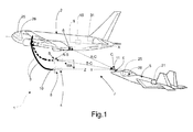
Figure 1 shows a schematic of an assisted in-flight refuelling system in accordance with the teachings of the present invention; -
Figure 2 shows a schematic of a drogue-probe coupling assist system forming part of the assisted in-flight refuelling system inFigure 1 ; -
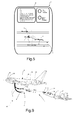
Figure 3 shows a schematic, partly sectioned side view, with parts removed for clarity, of a drogue control assembly of theFigure 1 system; -
Figure 4 shows a schematic, partly sectioned front view, with parts removed for clarity, of theFigure 3 drogue control assembly; -
Figure 5 shows a schematic of one example of a user interface of theFigure 2 drogue-probe coupling assist system; -
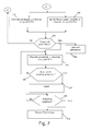
Figures 6 and7 show a flow chart of the drogue-probe coupling operations performed by theFigure 1 assisted in-flight refuelling system; -
Figure 8 shows a flow chart of the differential distance calculations performed by the drogue-probe coupling assist system; -
Figures 9 and10 show schematics of two variations of the assisted in-flight refuelling system. -
Number 1 inFigure 1 indicates as a whole an assisted in-flight refuelling system comprising afuel tanker aircraft 2 equipped with a fuel hose 3, which extends fromtanker aircraft 2 so that, in flight, an end portion of hose 3 is positioned substantially parallel to the longitudinal axis X oftanker aircraft 2, and is connected at its free end to adrogue 4. - Assisted in-
flight refuelling system 1 also comprises a fuel take-onaircraft 5 equipped with arigid probe 6, which preferably, though not necessarily, projects along a longitudinal axis Z from the front of the fuselage of take-onaircraft 5, and is shaped to couple withdrogue 4 to allowtanker aircraft 2 to supply take-onaircraft 5 with the required amount of fuel. - In the
Figure 1 and2 example,refuelling system 1 comprises a drogue-probecoupling assist system 7 configured to determine a distance betweendrogue 4 andprobe 6; a distance betweentanker aircraft 2 anddrogue 4; a distance betweentanker aircraft 2 and take-onaircraft 5; and the displacement ofdrogue 4 and/or of take-onaircraft 5 necessary to achieve drogue-probe coupling, as a function of the three distances. - In the
Figure 1 example, drogue-probecoupling assist system 7 comprises three positioning modules, one fitted totanker aircraft 2, one insidedrogue 4, and one fitted toaircraft 5, preferably though not necessarily atprobe 6. - In the
Figure 1 embodiment, one of the three positioning modules comprises a differential satellitepositioning master module 9 configured to determine its own absolute position; and the other two positioning modules comprise respective differential satellitepositioning slave modules positioning master module 9. - In the example shown, differential satellite
positioning master module 9 is designed to determine and transmit its own instantaneous absolute position PA and a differential correction C-RTK (both described in detail below); and each differential satellitepositioning slave module positioning master module 9. - Drogue-probe
coupling assist system 7 is also designed to control displacement ofdrogue 4 as a function of the distances determined by differential satellitepositioning slave modules - Drogue-probe
coupling assist system 7 also comprises adrogue control assembly 8, which is preferably, though not necessarily, fitted to the free end of hose 3 (as in theFigure 3 example) or is integrated in drogue 4 (in a variation not shown), and provides for shiftingdrogue 4, on command, in one or more directions substantially crosswise to the hauling/travelling direction WA ofdrogue 4. - Differential satellite
positioning master module 9 comprises a DGPS/RTK (Differential Global Positioning System/Real Time Kinematic) satellite positioning device designed to continuously determine : its own absolute position PA in space in terms of latitude, longitude, and altitude; its own travelling speed VA; and its own heading angle HA. - In connection with the above, it should be pointed out that, in the
Figure 1 example, absolute position PA, speed VA, and heading angle HA measured by the DGPS/RTK satellite positioning device are associated withtanker aircraft 2. - The DGPS/RTK satellite positioning device of differential satellite
positioning master module 9 implements an RTK (Real Time Kinematic) algorithm, which determines the differential correction C-RTK to be made to the GPS satellite system measurement. - The RTK algorithm implemented by the DGPS/RTK satellite positioning device of differential satellite
positioning master module 9 is known and therefore not described in detail, except to state that the differential correction C-RTK corresponds to the corrections to be made to the CPM (Carrier Phase Measurement) of the satellite signal employed by the DGPS/RTK satellite positioning device to calculate absolute position PA. - It should also be pointed out that the DGPS/RTK satellite positioning device of differential satellite
positioning master module 9 is conveniently designed, as explained in detail below, to determine its own position PA and correction C-RTK by means of a computing algorithm suitable for a mobile, as opposed to stationary, positioning base. In the solution proposed, in fact, the DGPS/RTK satellite positioning device is mounted on a moving object, corresponding in this case totanker aircraft 2, so differential satellitepositioning master module 9 is designed to implement a computing algorithm capable of taking into account the movement of the object on which it is installed. - Differential satellite
positioning master module 9 is also designed to transmit absolute position PA, speed VA, heading angle HA, and differential correction C-RTK by means of atransceiver module 12. - The differential satellite
positioning slave module 10 indrogue 4 comprises a DGPS/RTK satellite positioning device (not shown) designed to receive absolute position PA, speed VA, heading angle HA, and differential correction C-RTK by means of atransceiver module 13. - As explained below, differential satellite
positioning slave module 10 is designed to determine its own position with respect to absolute position PA of differential satellitepositioning master module 9. - In the example shown, differential satellite
positioning slave module 10 is designed to determine its own distance A-B with respect to differential satellitepositioning slave module 9 on the basis of absolute position PA and the differential correction C-RTK processed by differential satellitepositioning master module 9. - Accordingly, differential satellite
positioning slave module 10 comprises a computing unit (not shown), which receives the relative position determined by the DGPS/RTK satellite positioning device, and the absolute position PA and differential correction C-RTK transmitted by differential satellitepositioning master module 9, and accordingly determines the distance A-B between differential satellitepositioning master module 9 and differential satellitepositioning slave module 10. - Differential satellite
positioning slave module 10 is also designed to determine and transmit its own relative position; its own distance A-B corrected on the basis of differential correction C-RTK; its own speed V1; and its own heading angle H1. It should be pointed out that speed V1 and heading angle H1 correspond to the speed and heading angle of the object on which differential satellitepositioning slave module 10 is installed, i.e.drogue 4. - Differential satellite
positioning slave module 11, which, in the example shown, is located onaircraft 5, comprises a DGPS/RTK satellite positioning device designed to receive absolute position PA, speed VA, heading angle HA, and differential correction C-RTK by means of atransceiver module 14, and to determine its own position with respect to differential satellitepositioning master module 9. - More specifically, as explained below, differential satellite
positioning slave module 11 is designed to determine and transmit its own position and distance A-C with respect to differential satellitepositioning master module 9 on the basis of absolute position PA and differential correction C-RTK. - Accordingly, differential satellite
positioning slave module 11 comprises a computing unit (not shown), which receives the relative position determined by the DGPS/RTK satellite positioning device, and the absolute position PA and differential correction C-RTK transmitted by differential satellitepositioning master module 9, and accordingly determines the distance A-C between differential satellitepositioning master module 9 and differential satellitepositioning slave module 11. - Differential satellite
positioning slave module 11 is also designed to determine and transmit its own speed V2 and heading angle H2, which correspond to the speed and heading angle ofprobe 6/take-onaircraft 5. - Drogue-probe
coupling assist system 7 also comprises acomputing device 15, which is configured to receive distances A-B and A-C by means of atransceiver module 17, and to determine the distance B-C between the drogue and probe using a geometric calculation algorithm and on the basis of distances A-B and A-C. - In the
Figure 1 example,computing device 15 is preferably, though not necessarily, installed ontanker aircraft 2, and is designed to exchange information viatransceiver module 17 with each of differentialsatellite positioning modules communication system 16. In the example shown,transceiver modules - In connection with the above, it should be pointed out that, in an embodiment not shown,
computing device 15, as opposed to being installed ontanker aircraft 2, may conveniently be installed inprobe 6, or on take-onaircraft 5, or indrogue 4; and differentialsatellite positioning modules tanker aircraft 2,drogue 4, andprobe 6 in any arrangement other than the one described. In other words, differential satellitepositioning master module 9, i.e. the module calculating absolute position PA and differential correction C-RTK, may be installed on take-onaircraft 5, and differentialsatellite positioning modules tanker aircraft 2 and indrogue 4. - In one embodiment, differential satellite
positioning master module 9 is installed indrogue 4, and differentialsatellite positioning modules tanker aircraft 2 and take-onaircraft 5. - In connection with the above, it should be pointed out that, in each of the above three installation configurations of the differential satellite positioning master and slave modules on the tanker aircraft/drogue/take-on aircraft,
computing device 15 receives two distances calculated by the two differential satellite positioning slave modules, and accordingly calculates the third distance using a calculation based on euclidean geometry. - Another important point to note is that using the DGPS/RTK satellite positioning devices described has the major advantage, unlike conventional GPS devices of roughly one metre precision, of obtaining distance measurements of roughly one centimetre precision, which is vital for automatically connecting
probe 6 todrogue 4. - In the
Figure 3 and 4 embodiment,drogue control assembly 8 comprises acasing 16 which fits firmly todrogue 4 or to the end portion of hose 3 (as shown inFigure 3 ); a number ofdeflecting fins 18, each extending radially fromcasing 16 and fitted to the casing to rotate about a respective axis of rotation Xi and generate, ondrogue 4 in flight, a force WTi crosswise to axis of rotation Xi; and a number ofactuators 19, each fitted firmly tocasing 16 and to afin 18 to rotate fin 18 about axis of rotation Xi. - More specifically, in the example shown schematically in
Figures 3 and 4 ,casing 16 is substantially cylindrical and designed to fit firmly to the end portion of hose 3; and deflecting fins 18 project fromcasing 16 to form a substantially cross-shaped structure. Twohorizontal fins 18 rotate about respective axes Xi to generate a crosswise force WTi by which to movedrogue 4 up or down; and twovertical fins 18 rotate about respective axes Xi to generate a crosswise force WTi by which to movedrogue 4 both ways in a substantially horizontal direction. -
Drogue control assembly 8 also comprises anelectronic control module 20, which is designed to receive a control signal SCOM via a transceiver module, and commands rotation offins 18 byactuators 19 on the basis of control signal SCOM to movedrogue 4. - In connection with the above, it should be pointed out that
electronic control module 20 is preferably, though not necessarily, designed to control rotation offins 18 on the basis of control signal SCOM and also on the basis of an acceleration signal from an inertial sensor (not shown), in particular a set of three accelerometers ondrogue 4. -
Computing device 15 inFigure 2 is designed to continuously process drogue-probe distance B-C, and preferably heading H1 and speed V1 ofdrogue 4, heading H2 and speed V2 ofprobe 6, and heading HA and speed V2 oftanker aircraft 2, to determine the transverse (vertical/horizontal) movements ofdrogue 4 and/or take-onaircraft 5 necessary to align the respective longitudinal axes Z and Y ofdrogue 4 andprobe 6. - More specifically,
computing device 15 is supplied continuously by differentialsatellite positioning modules drogue 4, and/or information relative to the necessary vertical/horizontal movement of take-onaircraft 5. - Accordingly, drogue-probe
coupling assist system 7 may comprise a take-onaircraft autopilot system 21, which receives control signal SCOM and automatically controls take-onaircraft 5 to move it vertically and/or horizontally according to the movements contained in control signal SCOM. - In the
Figure 2 example, the take-onaircraft autopilot system 21 comprises asignal transceiver module 22 which receives control signal SCOM fromcomputing device 15; aprocessing module 23 which receives control signal SCOM and accordingly determines the necessary movement of take-onaircraft 5; and a knownaircraft autopilot device 24, which is supplied byprocessing module 23 with information relative to the necessary movement ofaircraft 5, andpilots aircraft 5 to move it vertically and/or horizontally according to the information received. -
Computing device 15 is also designed to generate, as a function of distance A-B, a first alarm signal AL1 containing distance A-B and indicating a first hazard situation caused bydrogue 4 coming dangerously close totanker aircraft 2. - For example,
computing device 15 may be designed to generate first alarm signal AL1 when distance A-B falls below a first safety threshold representing the minimum safety distance betweendrogue 4 andtanker aircraft 2. - It should be pointed out that alarm signal AL1 may be generated not only to indicate a hazard situation, but also to indicate an improper position of
drogue 4 with respect totanker aircraft 2 and capable of damaging hose 3. -
Computing device 15 is also designed to generate, as a function of distance A-C, a second alarm signal AL2 containing distance A-C and indicating a second hazard situation caused by take-onaircraft 5 coming dangerously close totanker aircraft 2. -
Computing device 15 may be designed to generate second alarm signal AL2 when distance A-C falls below a second safety threshold representing the minimum safety distance between take-onaircraft 5 andtanker aircraft 2. - Drogue-probe coupling assist
system 7 also comprises one ormore user interfaces 25, each designed to receive information relative to absolute position PA, drogue-probe distance B-C, and/or heading H1 and/or speed V1 ofdrogue 4, and/or heading H2 and/or speed V2 ofprobe 6/take-onaircraft 5, heading HA and speed VA oftanker aircraft 2, and to communicate this information to the pilot to assist the pilot in coupling the probe to the drogue. - More specifically, in the
Figure 5 example, eachuser interface 25 comprises a screen ordisplay 29, which provides the pilot with a continuous graphic display of : a predetermined, preferably, though not necessarily, two-dimensional reference system 30; position PA and the course/direction/heading oftanker aircraft 2; position P1 and the course/direction/heading ofdrogue 4; and position P2 and the course/direction/heading of probe 6 (take-on aircraft 5). - Each
user interface 25 is also designed to continuously communicate to the pilot : speed VA oftanker aircraft 2, and/or speed V1 ofdrogue 4, and/or speed V2 ofprobe 6, and/or distances A-B, A-C and B-C. - Each
user interface 25 is also designed to receive first alarm signal AL1 and/or second alarm signal AL2, and to generate an alarm message indicating the first and/or second hazard situation and/or measured distances A-B, A-C. - Accordingly,
user interface 25 may comprise a device for producing audio or visual messages containing the information relative to the first and/or second alarm situation. - In the
Figure 1 and2 example, drogue-probe coupling assistsystem 7 comprises twouser interfaces 25, one installed in thecockpit 26 oftanker aircraft 2 and designed to exchange information with differential satellitepositioning master module 9, and the other installed in thecockpit 28 of take-onaircraft 5 and designed to exchange information with differential satellitepositioning slave module 11. -
Computing device 15 may also be designed to transmit first alarm signal AL1 and/or second alarm signal AL2; andautopilot system 21 may be designed to receive second alarm signal AL2 and control the movement of take-onaircraft 5 with respect totanker aircraft 2 as a function of distance A-C in alarm signal AL2, to restore take-onaircraft 5 to a safe position with respect totanker aircraft 2. - In one embodiment, electronic
drogue control module 20 is designed to receive first alarm signal AL1, and commandscontrol assembly 8 to movedrogue 4 with respect totanker aircraft 2 as a function of distance A-B in alarm signal AL1, and so restoredrogue 4 to a safe position with respect totanker aircraft 2. - An operating method implemented by assisted in-
flight refuelling system 1 as described above, and with the positioning module configuration shown in theFigure 1 example, will now be described with reference toFigures 6 ,7 and8 . - The operating method comprises a first step, in which
tanker aircraft 2 moves in a straight line at constant speed, and take-onaircraft 5 begins approaching tanker aircraft 2 (block 100). - At this point, differential satellite
positioning slave module 11 calculates and transmits distance A-C to computing device 15 (block 110), which determines, as a function of distance A-C, the presence or not of the second hazard situation caused by take-onaircraft 5 coming dangerously close to tanker aircraft 2 (block 120). - At this stage (block 120),
computing device 15 performs the second-hazard-situation check and determines the presence of the second hazard situation when distance A-C, for example, is below the second safety threshold representing the minimum safety distance betweentanker aircraft 2 and take-on aircraft 5 (YES output of block 120). - In the event the second hazard situation is determined,
computing device 15 commands transmission of the second alarm signal AL2 (block 130). - The second alarm signal AL2 is sent to
interfaces 25 and/or take-onaircraft autopilot system 21. -
Interfaces 25 generate an alarm message to assist the pilots by alerting them to the hazard situation, and to enable the pilots to intervene manually to restorerespective aircraft - At this stage,
autopilot system 21 may intervene independently, i.e. may pilot take-onaircraft 5 automatically as a function of second alarm signal AL2, to move it away from and back to a safe distance from tanker aircraft 2 (block 150). - Conversely, if no second hazard situation is determined during approach, the pilot proceeds to move take-on
aircraft 5 into an optimum approach position. - This may be done manually, i.e. solely by the pilot, or fully automatically.
- In manual control mode, the pilot of take-on
aircraft 5 moves the aircraft into the optimum position by observing the positions of the two aircraft and/or the probe/drogue positions displayed onuser interface 25 incockpit 28. - Alternatively, in automatic mode,
computing device 15 is designed to determine the best approach trajectory as a function of distance A-C and speeds VA oftanker aircraft 2 and V2 of take-onaircraft 5 measured by respective differential satellite positioning master andslave modules - More specifically,
computing device 15 is designed to continuously calculate, as a function of distance A-C and speeds VA and V2, the necessary movement/s and speed of take-onaircraft 5 to move it into the docking position, and transmits this information toautopilot system 21. - At this point,
autopilot system 21 is therefore able to pilotaircraft 5 automatically as a function of the movement/speed information determined by computingdevice 15. - In the
event aircraft 5 fails to move into the docking position (NO output of block 180), the method repeats the operations in blocks 110-160. - Conversely, in the
event aircraft 5 succeeds in moving into the docking position (YES output of block 180), the method commences the drogue-probe coupling procedure. - At this point, differential satellite
positioning slave module 10 determines and transmits distance A-B to computingdevice 15, which calculates distance B-C on the basis of distance A-B and the distance A-C determined and transmitted by differential satellite positioning slave module 11 (block 190). - At this point,
computing device 15 determines, on the basis of distance A-B, the presence or not of the first hazard situation caused bydrogue 4 coming dangerously close to tanker aircraft 2 (block 200). - At this stage,
computing device 15 performs the first-hazard-situation check and determines the presence of the first hazard situation (YES output of block 200) when distance A-B, for example, is below the first safety threshold representing the minimum safety distance between the drogue andtanker aircraft 2. - In the event the first hazard situation is determined,
computing device 15 transmits first alarm signal AL1 (block 210), which in this case is sent tointerfaces 25 and/orelectronic control module 20. -
Interface 25 generates an alarm message to alert the pilot oftanker aircraft 2 to the hazard situation, and to enable the pilot to intervene to restoretanker aircraft 2 to a distance greater than or equal to the minimum safety distance from drogue 4 (block 220). - At this stage,
electronic control module 20 ofdrogue control assembly 8 also controlsdrogue 4 automatically to move it away fromtanker aircraft 2 to a distance greater than or equal to the safety distance (block 230). It should be pointed out that this is done as a function of distance A-B contained in first alarm signal AL1. - Conversely, in the event the first hazard situation is not determined,
computing device 15 is supplied continuously by differentialsatellite positioning modules drogue 4 and/or information relative to the necessary vertical/horizontal movement of take-onaircraft 5 to achieve drogue-probe coupling. - In the example shown, this stage may preferably, though not necessarily, comprise transforming the distance B-C vector according to a first reference system containing latitude, longitude and altitude, into a distance B-C vector according to a UTM (Universal Transverse Mercatore) reference system (not shown).
- The UTM reference system can be represented by a cartesian grid with three perpendicular axes, in which the x axis UTME (not shown) extends in an East-West land direction, the y axis UTMN (not shown) extends in a North-South land direction and defines a plane UTMEN (not shown) with the x axis UTME (not shown), and the third axis UTMZ (not shown) is associated with the vertical coordinates, i.e. directly with height.
- Assuming the third component is zero, i.e. axis Y of
probe 6 and drogue axis Z are both at the same height,computing device 15 can transform the distance B-C vector according to the first reference system into a distance B-C vector according to the UTM reference system, and can then rotate the B-C vector in plane UTMNE by an angle equal to heading H2 of take-onaircraft 5, to obtain a transverse component and a longitudinal component of vector B-C with respect to the direction of take-on aircraft 5 (block 240). - The transverse and longitudinal components of vector B-C so obtained represent information relative to the movement to be coded in control signal SCOM (block 250).
- At this point,
computing device 15 transmits control signal SCOM to electronic control module 20 (block 260), which controls the movement ofdrogue 4, by means ofactuators 19, as a function of the movements contained in control signal SCOM (block 280). - In one embodiment, control signal SCOM is sent to
autopilot system 21, which movesaircraft 5 automatically on the basis of the movements contained in control signal SCOM (block 270). - At this point,
computing device 15 determines, as a function of distance B-C, whether respective longitudinal axes Z and Y of the drogue andprobe 6 are aligned (block 290). - If they are not (NO output of block 290), the method repeats the operations in blocks 190-280; conversely, if longitudinal axes Z and Y are aligned,
computing device 15 transmits a signal containing information indicating drogue-probe alignment, and authorizing take-onaircraft 5 to approachdrogue 4. More specifically, this signal is sent touser interface 25, which generates a message informing the pilot of drogue-probe alignment, and requesting the pilot to moveaircraft 5 towardsdrogue 4. - At this point, the pilot moves take-on
aircraft 5 forward in a straight line to insertprobe 6 inside drogue 4 (block 300). - In one embodiment, once axes Z and Y are aligned,
computing device 15 determines, as a function of speeds VA, V1, V2 and distance B-C, the necessary adjustments to speed V2 of the take-on aircraft to achieve drogue-probe coupling (block 310). - At this stage,
computing device 15 transmits a signal SCA, containing commands to adjust speed V2, to autopilotsystem 21, which proceeds to moveaircraft 5 forward fully automatically, making the speed adjustments contained in signal SCA. - Obviously, if
drogue 4 andprobe 6 are perfectly aligned, and speeds V1, V2 and headings H1, H2 of the drogue and probe correspond, drogue-probe coupling may be completed solely on the basis of distance B-C. -
Computing device 15 determines successful drogue-probe coupling when distance B-C is zero (block 320). - If coupling is not achieved (NO output of block 320), the method repeats the operations in blocks 310-320.
- Once drogue-probe coupling is achieved (YES output of block 320),
computing device 15 commands refuelling (block 330) and, once refuelling is completed (YES output of block 340), commands release of the drogue and probe by supplyinguser interfaces 25 with a signal containing information indicating refuelling is completed, and a request to release the drogue and probe and distance the two aircraft. - With reference to
Figure 8 , distances A-B, A-C, B-C are calculated continuously bysystem 7 described above, substantially by the DGPS/RTK satellite positioning device of differential satellitepositioning master module 9 determining its own absolute position PA in space in terms of latitude, longitude and altitude, and implementing the RTK algorithm, which determines differential correction C-RTK related to the intrinsic error in the PA measurement by the GPS satellite system (block 400). - Differential satellite
positioning master module 9 then transmits absolute position PA and differential correction C-RTK to differential satellitepositioning slave modules 10 and 11 (block 410). - On receiving the information transmitted by differential satellite
positioning master module 9, differential satellitepositioning slave module 11 determines distance A-C as a function of its own position with respect to position PA and on the basis of differential corrections C-RTK, and transmits distance A-C to computing device 15 (block 430). - On receiving the information transmitted by differential satellite
positioning master module 9, differential satellitepositioning slave module 10 determines distance A-B as a function of its own position with respect to position PA and on the basis of differential corrections C-RTK, and transmits distance A-B to computing device 15 (block 420). - At this point,
computing device 15 calculates distance B-C by means of a euclidean geometric calculation on the basis of distances A-C and A-B (block 440). - The in-flight refuelling system described has the following advantages.
- First and foremost, using DGPS/RTK satellite positioning devices gives a distance measuring precision of roughly a centimetre by which to achieve drogue-probe coupling, unlike conventional GPS satellite systems with a measuring precision of several metres.
- The system greatly reduces the work load on the pilots at the drogue-probe coupling stage. In fact, even in the simplest solution, in which take-on aircraft approach is performed manually, the pilot can control the take-on aircraft on the basis of the positions displayed on the user interface, with no need to keep track of the position of the tanker aircraft and/or drogue outside the cockpit. In other words, the pilot has the advantage of being able to control approach by simply concentrating on the graphic position information displayed on the user interface, regardless of weather conditions, and even at night.
- The variation featuring automatic take-on aircraft approach and/or automatic drogue-probe coupling on the basis of the movements determined by the computing device obviously not only greatly reduces pilot stress, but also enables refuelling to be completed within a predetermined time, regardless of weather conditions.
- The system described therefore has the advantage of being able to preprogram in-flight refuelling of a given number of aircraft, while at the same time drastically reducing the risk of refuelling failure.
- Clearly, changes may be made to the system described without, however, departing from the scope of the present invention as defined in the accompanying Claims.
- More specifically, the
Figure 9 embodiment relates to an in-flight refuelling system 40 similar to in-flight refuelling system 1, and the component parts of which are indicated, where possible, using the same reference numbers as for the corresponding parts ofsystem 1. - Refuelling
system 40 differs fromrefuelling system 1 by a differential satellite positioning slave module of drogue-probe coupling assistsystem 7 being replaced with a measuringdevice 41 for measuring distance A-B betweentanker aircraft 2 anddrogue 4. - More specifically, measuring
device 41 may be a known optoelectronic laser device, not described in detail, or any other similar electronic device for measuring the distance between two objects. - In the
Figure 9 embodiment, differential satellitepositioning master module 9 is mounted directly ondrogue 4, and differential satellitepositioning slave module 11 is mounted on take-onaircraft 5. - In this case, distance B-C is determined directly by differential satellite
positioning slave module 11 on take-onaircraft 5; distance A-B is measured by measuringdevice 41; distance A-C is determined by computingdevice 15 as a function of distances B-C and A-B; and drogue-probe coupling assistsystem 7 provides forcoupling drogue 4 andprobe 6, as described in theFigure 6 ,7 and8 flow charts, on the basis of distances A-B, B-C and A-C. - Obviously, differential satellite
positioning master module 9 may be mounted directly on take-onaircraft 5, and differential satellitepositioning slave module 11 may be mounted indrogue 4. - The
Figure 10 embodiment relates to an assisted in-flight refuelling system 50 similar to in-flight refuelling system 1, and the component parts of which are indicated, where possible, using the same reference numbers as for the corresponding parts ofsystem 1. - Assisted in-
flight refuelling system 50 differs from assistedrefuelling system 1 by a differential satellite positioning slave module of drogue-probe coupling assistsystem 7 being replaced with a measuringdevice 51 for measuring distance B-C between take-onaircraft 5 anddrogue 4. - More specifically, measuring
device 51 may be a known optoelectronic laser device, not described in detail, or any other similar electronic device for measuring the distance between the object on which it is installed and another object. - In the
Figure 10 embodiment, differential satellitepositioning master module 9 is mounted ontanker aircraft 2, and differential satellitepositioning slave module 10 is mounted directly ondrogue 4. - In this case, distance B-C is determined directly by measuring
device 51 mounted on take-onaircraft 5; distance A-B is measured by differential satellitepositioning master module 9; distance A-C is determined by computingdevice 15 as a function of distances B-C and A-B; and drogue-probe coupling assistsystem 7 provides forcoupling drogue 4 andprobe 6 using the same control procedure described in theFigure 6 ,7 and8 flow charts, on the basis of distances A-B, B-C and A-C. - In a variation not shown, assisted in-
flight refuelling system 1 comprises a number of take-onaircraft 5, each comprising a DGPS/RTK positioning module 11. -
Computing device 15 of drogue-probe coupling assistsystem 7 is designed to continuously determine the relative speed between each take-onaircraft 5 andtanker aircraft 2 on the basis of the information generated by therespective positioning module 11. -
Computing device 15 also determines distance A-C between each take-onaircraft 5 andtanker aircraft 2, so as to determine the direction of each take-onaircraft 5 as a function of distance A-C and the relative speed between take-onaircraft 5 andtanker aircraft 2. -
Computing device 15 informs the pilot oftanker aircraft 2, overuser interface 25 ontanker aircraft 2, of the position and travelling direction of each take-onaircraft 5 with respect totanker aircraft 2. -
Computing device 15 may also be designed to inform the pilot of each take-onaircraft 5, overrespective user interface 25, of the position and travelling direction of each take-onaircraft 5 with respect totanker aircraft 2.
Claims (16)
- An assisted in-flight refuelling system (1) for a fuel take-on aircraft (5) comprising a probe (6); the assisted in-flight refuelling system comprising a tanker aircraft (2), and a drogue (4) connected to the tanker aircraft (2) by a hose (3) and drawn by the tanker aircraft (2) in a predetermined travelling direction (WA);
said assisted in-flight refuelling system (1) being characterized by comprising an electronic flight control system (7) comprising :- three DGPS/RTK positioning modules (10)(11)(9) installed respectively on said drogue (4), said take-on aircraft (5), and said tanker aircraft (2) to determine a first quantity indicating a first distance (B-C) between said drogue (4) and said probe (6); a second quantity indicating a second distance (A-B) between said tanker aircraft (2) and said drogue (4); and a third quantity indicating a third distance (A-C) between said tanker aircraft (2) and said probe (6); and- electronic control means (15) designed to cooperate with the three positioning modules (9)(10)(11) to determine, as a function of said first (B-C), second (A-B), and third (A-C) distance, the necessary movement of said drogue (4) and/or the necessary movement of said take-on aircraft (5) to couple the drogue (4) to the probe (6). - An assisted in-flight refuelling system (1) as claimed in Claim 1, wherein said electronic flight control system (7) comprises control means (18, 19) mounted on the drogue (4) to move the drogue (4) in one or more transverse directions crosswise to the travelling direction (WA);
said electronic control means (15) being designed to control said control means (18, 19) as a function of said first (B-C), second (A-B), and third (A-C) distance, so as to move the drogue (4) in one or more transverse directions crosswise to said travelling direction (WA), and align the longitudinal axis of the drogue (4) with the longitudinal axis of said probe (6). - An assisted in-flight refuelling system (1) as claimed in Claim 1 or 2, wherein said electronic flight control system (7) comprises electronic automatic control means (21) installed on the take-on aircraft (5) and designed to automatically pilot said take-on aircraft (5) as a function of said first (B-C), second (A-B), and third (A-C) distance, to align said probe (6) with said drogue (4).
- An assisted in-flight refuelling system (1) as claimed in any one of the foregoing Claims, wherein said electronic flight control system (7) comprises at least one user interface (25) installed on said tanker aircraft (2) and/or said take-on aircraft (5); said user interface (25) being designed to provide the user with the instantaneous position (PA) of said tanker aircraft (2), and/or the instantaneous position (P1) of said drogue (4), and/or the instantaneous position (P2) of said take-on aircraft (5) as a function of said first (B-C), second (A-B), and third (A-C) distance.
- An assisted in-flight refuelling system (1) as claimed in any one of the foregoing Claims, wherein said electronic flight control system (7) is designed to determine a hazard situation and generate a first alarm signal (AL2), indicating said take-on aircraft (5) coming dangerously close to said tanker aircraft (2), when said third distance (A-C) is below a predetermined first threshold.
- An assisted in-flight refuelling system (1) as claimed in Claim 5, wherein said electronic control means (15) are designed to cooperate with said electronic automatic control means (21) to move said take-on aircraft (5) to a distance greater than or equal to a predetermined safety distance from said tanker aircraft (2) as a function of said first alarm signal (AL2).
- An assisted in-flight refuelling system (1) as claimed in Claims 4 and 5, wherein, on receiving said first alarm signal (AL2), each said user interface (25) is designed to send the pilot an alarm message indicating said take-on aircraft (5) coming dangerously close to said tanker aircraft (2).
- An assisted in-flight refuelling system (1) as claimed in any one of Claims 4 to 7, wherein said electronic flight control system (7) is designed to generate a second alarm signal (AL1), indicating said drogue (4) coming dangerously close to said tanker aircraft (2), when said second distance (A-B) is below a predetermined second threshold.
- An assisted in-flight refuelling system (1) as claimed in Claim 8, wherein said electronic control means (15) are designed to cooperate with said electronic automatic control means (21) to move said drogue (4) automatically in said transverse directions, by means of said control means (18, 19), to a distance greater than or equal to a predetermined safety distance from said tanker aircraft (2) as a function of said second alarm signal (AL1).
- An assisted in-flight refuelling system (1) as claimed in Claims 4 and 8, wherein said user interfaces (25) are designed to receive said second alarm signal (AL1) and supply the pilot with an alarm message indicating said drogue (4) coming dangerously close to said tanker aircraft (2).
- An assisted in-flight refuelling system (1) for a fuel take-on aircraft (5) comprising a probe (6); the assisted in-flight refuelling system comprising a tanker aircraft (2), and a drogue (4) connected to the tanker aircraft (2) by a hose (3) and drawn by the tanker aircraft (2) in a predetermined travelling direction (WA);
said assisted in-flight refuelling system (1) being characterized by comprising an electronic flight control system (7), which comprises control means (18, 19) mounted on the drogue (4) to move the drogue (4) in one or more transverse directions crosswise to said travelling direction (WA), and is designed to :- determine a first quantity indicating a first distance (B-C) between said drogue (4) and said probe (6); a second quantity indicating a second distance (A-B) between said tanker aircraft (2) and said drogue (4); and a third quantity indicating a third distance (A-C) between said tanker aircraft (2) and said probe (6);- supply information indicating the necessary movement of the take-on aircraft (5) to move it into a predetermined docking position, as a function of the third distance (A-C), the speed (VA) of said tanker aircraft (2), and the speed (V2) of said take-on aircraft (5);- operate the control means (18, 19), once the take-on aircraft (5) is in said predetermined docking position, to move said drogue (4) in one or more transverse directions crosswise to said travelling direction (WA), to align said drogue (4) with said probe (6); and- once the drogue (4) is aligned with the probe (6), supply information indicating the necessary straight-line movement of the take-on aircraft (5) towards said drogue (4), as a function of said first distance (B-C), to couple the probe to the drogue (4). - An assisted in-flight refuelling system (1) as claimed in Claim 11, wherein said electronic flight control system (7) comprises three DGPS/RTK positioning modules (9)(10)(11) installed respectively on said drogue (4), said take-on aircraft (5), and said tanker aircraft (2) to determine said first (B-C), second (A-B), and third (A-C) distance.
- An assisted in-flight refuelling system (1) as claimed in Claim 12, wherein said electronic flight control system (7) comprises a user interface (25) installed on said take-on aircraft (5) and designed to supply information to assist the pilot in manoeuvring the take-on aircraft (5) into the docking position and/or manoeuvring the take-on aircraft (5) to couple the probe (6) to the drogue (4).
- An assisted in-flight refuelling system (1) as claimed in Claim 12, wherein said electronic flight control system (7) comprises electronic automatic control means (21) installed on the take-on aircraft (5) and designed to pilot the take-on aircraft (5) automatically on the basis of said information for manoeuvring the take-on aircraft (5) into said docking position and/or the drogue-probe coupling position.
- An assisted in-flight refuelling system (1) as claimed in any one of Claims 12 to 14, and comprising a number of take-on aircraft (5), each comprising a DGPS/RTK positioning module (11); said electronic flight control system (7) being designed to continuously determine the relative speed of each take-on aircraft (5) with respect to said tanker aircraft (2), and the third distance (A-C) between each take-on aircraft (5) and the tanker aircraft (2).
- An assisted in-flight refuelling system (1) as claimed in Claim 15, wherein said electronic flight control system (7) comprises a number of user interfaces (25) installed respectively on said tanker aircraft (2) and each take-on aircraft (5);
said electronic flight control system (7) being designed to :- determine the position and/or travelling direction of each take-on aircraft (5) as a function of the third distance (A-C) and said relative speed;- inform the pilot, over the user interface (25) installed on the tanker aircraft (2), the position and/or travelling direction of each take-on aircraft with respect to said tanker aircraft (2); and/or- inform the pilot, over the user interface (25) installed on each take-on aircraft (5), the position and/or travelling direction of each take-on aircraft with respect to said tanker aircraft (2).
Applications Claiming Priority (1)
| Application Number | Priority Date | Filing Date | Title |
|---|---|---|---|
| ITTV2009A000116A IT1394808B1 (en) | 2009-06-04 | 2009-06-04 | SUPPLYING SUPPLY SYSTEM IN FLIGHT |
Publications (2)
| Publication Number | Publication Date |
|---|---|
| EP2266879A1 true EP2266879A1 (en) | 2010-12-29 |
| EP2266879B1 EP2266879B1 (en) | 2013-08-07 |
Family
ID=42041880
Family Applications (1)
| Application Number | Title | Priority Date | Filing Date |
|---|---|---|---|
| EP10164829.3A Active EP2266879B1 (en) | 2009-06-04 | 2010-06-03 | Assisted in-flight refuelling system |
Country Status (6)
| Country | Link |
|---|---|
| US (1) | US9334062B2 (en) |
| EP (1) | EP2266879B1 (en) |
| CA (1) | CA2706278C (en) |
| ES (1) | ES2437673T3 (en) |
| IT (1) | IT1394808B1 (en) |
| RU (1) | RU2548653C2 (en) |
Cited By (4)
| Publication number | Priority date | Publication date | Assignee | Title |
|---|---|---|---|---|
| WO2016046823A1 (en) * | 2014-09-22 | 2016-03-31 | Senecio Ltd. | Method and apparatus for artificial distribution of insects or spray |
| EP3842345A1 (en) * | 2020-10-29 | 2021-06-30 | Airbus Defence and Space, S.A.U. | Air to air active refuelling system and method for generating aerodynamic radial loads at a hose-end |
| EP3889037A1 (en) * | 2020-03-30 | 2021-10-06 | Cobham Mission Systems Wimborne Limited | Air-to-air refuelling drogue assembly |
| US11213006B2 (en) | 2014-12-04 | 2022-01-04 | Senecio Ltd. | Release method for insect distribution |
Families Citing this family (26)
| Publication number | Priority date | Publication date | Assignee | Title |
|---|---|---|---|---|
| US8232706B2 (en) | 2009-01-09 | 2012-07-31 | The Boeing Company | Autonomous power generation unit for auxiliary system on an airborne platform |
| US8398028B1 (en) * | 2010-11-16 | 2013-03-19 | The Boeing Company | Drogue with power generator |
| US9405010B2 (en) * | 2012-05-02 | 2016-08-02 | Raven Industries, Inc. | Geospatial positioning using correction information provided over cellular control channels |
| CN104219290B (en) * | 2014-08-19 | 2017-05-31 | 南京邮电大学 | A kind of multimode cloud application elasticity collocation method |
| CN105564663A (en) * | 2014-10-07 | 2016-05-11 | 刘跃进 | Airplane suspension type full-automatic take-off and landing system and take-off and landing method |
| US20160252351A1 (en) * | 2015-02-27 | 2016-09-01 | Ge Aviation Systems Llc | System and methods for providing situational awareness information for a relative navigation system |
| EP3093241A1 (en) * | 2015-05-11 | 2016-11-16 | BAE Systems PLC | Aircraft coupling method and system |
| ES2743489T3 (en) | 2015-05-11 | 2020-02-19 | Bae Systems Plc | Aircraft coupling method and system |
| RU2609539C1 (en) * | 2015-10-21 | 2017-02-02 | Николай Борисович Болотин | Rocket vehicle, return stage of rocket vehicle and method of its launch upon return and system of helicopter pick-up of return stage |
| CN106067272B (en) * | 2016-05-31 | 2019-03-08 | 中国航空工业集团公司西安飞机设计研究所 | A method for simulating the movement of a fueling rod of a fuel dispenser and a device for simulating the movement of a fueling rod of a fueling machine |
| CN105865772B (en) * | 2016-05-31 | 2019-04-23 | 中国航空工业集团公司西安飞机设计研究所 | A motion simulation method for oil receiving port components of oil receiving machine |
| IL253015B2 (en) * | 2017-06-18 | 2023-07-01 | Israel Aerospace Ind Ltd | System and method for refueling air vehicles |
| US10332294B2 (en) * | 2017-08-16 | 2019-06-25 | The Boeing Company | Methods and systems for head up display (HUD) of aerial refueling operation status and signaling |
| CN108674675A (en) * | 2018-05-13 | 2018-10-19 | 雷子墨 | A kind of mother and sons' tanker aircraft |
| GB2574078B (en) * | 2018-09-27 | 2020-05-20 | pitman James | Methods and systems for in-flight fuelling of aircraft |
| US11599323B2 (en) | 2020-09-28 | 2023-03-07 | Rockwell Collins, Inc. | Touchscreen boom pod |
| USD1006822S1 (en) | 2020-10-30 | 2023-12-05 | Rockwell Collins, Inc. | Touchscreen display boom graphical user interface |
| US11866192B2 (en) * | 2021-04-29 | 2024-01-09 | Sky Launch Corporation | System and method for reconnectably coupling an AFT vehicle to a forward vehicle in flight |
| DE102022110505B3 (en) | 2022-04-29 | 2023-08-31 | Deutsches Zentrum für Luft- und Raumfahrt e.V. | Pilot assistance for probe-and-drogue air refueling |
| CN115131993B (en) * | 2022-06-17 | 2023-07-21 | 中航西安飞机工业集团股份有限公司 | A Method for Calculating and Calibrating the Relative Position of Two Aircrafts During Refueling in the Air |
| US12528584B2 (en) | 2022-06-24 | 2026-01-20 | General Atomics Aeronautical Systems, Inc. | Relative navigation for aerial recovery of aircraft |
| WO2024015397A1 (en) | 2022-07-13 | 2024-01-18 | General Atomics Aeronautical Systems, Inc. | Systems and methods for airborne recovery and launch of aerial vehicles |
| DE102022123653B3 (en) | 2022-09-15 | 2024-02-29 | Deutsches Zentrum für Luft- und Raumfahrt e.V. | Assistance system to support a pilot when refueling an aircraft in the air |
| CN117602083A (en) * | 2023-12-29 | 2024-02-27 | 中国直升机设计研究所 | High-speed self-stabilizing two-way energy supplement platform, helicopter efficiency enhancement system and collaborative method |
| US20250319987A1 (en) * | 2024-04-10 | 2025-10-16 | The Boeing Company | Boom guidance system for automated air-to-air refueling |
| CN118790492B (en) * | 2024-08-27 | 2025-05-02 | 中国空气动力研究与发展中心空天技术研究所 | Spin wing ring type air refueling active stability-enhancing taper sleeve |
Citations (6)
| Publication number | Priority date | Publication date | Assignee | Title |
|---|---|---|---|---|
| WO1991006471A1 (en) * | 1989-10-27 | 1991-05-16 | Gec-Marconi Limited | Refueling apparatus |
| WO1993007055A1 (en) * | 1991-10-02 | 1993-04-15 | Enig Associates, Inc. | Controllable hose-and-drogue in-flight refueling system |
| WO1998007623A1 (en) * | 1996-08-19 | 1998-02-26 | Gosudarstvennoe Unitarnoe Predpriyatie 'pilotazhno-Issledovatelsky Tsentr' | In-flight aircraft refuelling system |
| WO2001002875A2 (en) * | 1999-06-21 | 2001-01-11 | Lockheed Martin Corporation | System and method for locating and maintaining objects in free space |
| WO2002024529A1 (en) * | 2000-09-21 | 2002-03-28 | Richard Lawrence Ken Woodland | Roll on - roll off, portable aerial spraying, particulate dispersal, and refueling systems apparatus |
| US20050114023A1 (en) * | 2003-11-26 | 2005-05-26 | Williamson Walton R. | Fault-tolerant system, apparatus and method |
Family Cites Families (10)
| Publication number | Priority date | Publication date | Assignee | Title |
|---|---|---|---|---|
| US3285544A (en) * | 1964-02-26 | 1966-11-15 | Industrial Nucleonics Corp | Mid-air refueling system |
| US4025193A (en) * | 1974-02-11 | 1977-05-24 | The Boeing Company | Apparatus suitable for use in orienting aircraft in-flight for refueling or other purposes |
| US5109345A (en) * | 1990-02-20 | 1992-04-28 | The United States Of America As Represented By The Administrator Of The National Aeronautics And Space Administration | Closed-loop autonomous docking system |
| RU2142897C1 (en) * | 1994-08-19 | 1999-12-20 | Анатолий Викторович Егоршев | Tanker aeroplane |
| US6752357B2 (en) * | 2002-05-10 | 2004-06-22 | The Boeing Company | Distance measuring using passive visual means |
| US6819982B2 (en) * | 2002-11-26 | 2004-11-16 | The Boeing Company | Uninhabited airborne vehicle in-flight refueling system |
| US6969030B1 (en) * | 2004-07-14 | 2005-11-29 | Macdonald Dettwiler Space And Associates Inc. | Spacecraft docking mechanism |
| US7681839B2 (en) * | 2005-02-25 | 2010-03-23 | Smiths Aerospace Llc | Optical tracking system for refueling |
| US8132759B2 (en) * | 2007-03-21 | 2012-03-13 | The Boeing Company | System and method for facilitating aerial refueling |
| US8757548B2 (en) * | 2007-04-30 | 2014-06-24 | The Boeing Company | Apparatus for an automated aerial refueling boom using multiple types of sensors |
-
2009
- 2009-06-04 IT ITTV2009A000116A patent/IT1394808B1/en active
-
2010
- 2010-06-02 US US12/792,440 patent/US9334062B2/en not_active Expired - Fee Related
- 2010-06-02 CA CA2706278A patent/CA2706278C/en not_active Expired - Fee Related
- 2010-06-03 EP EP10164829.3A patent/EP2266879B1/en active Active
- 2010-06-03 RU RU2010122757/11A patent/RU2548653C2/en not_active IP Right Cessation
- 2010-06-03 ES ES10164829.3T patent/ES2437673T3/en active Active
Patent Citations (6)
| Publication number | Priority date | Publication date | Assignee | Title |
|---|---|---|---|---|
| WO1991006471A1 (en) * | 1989-10-27 | 1991-05-16 | Gec-Marconi Limited | Refueling apparatus |
| WO1993007055A1 (en) * | 1991-10-02 | 1993-04-15 | Enig Associates, Inc. | Controllable hose-and-drogue in-flight refueling system |
| WO1998007623A1 (en) * | 1996-08-19 | 1998-02-26 | Gosudarstvennoe Unitarnoe Predpriyatie 'pilotazhno-Issledovatelsky Tsentr' | In-flight aircraft refuelling system |
| WO2001002875A2 (en) * | 1999-06-21 | 2001-01-11 | Lockheed Martin Corporation | System and method for locating and maintaining objects in free space |
| WO2002024529A1 (en) * | 2000-09-21 | 2002-03-28 | Richard Lawrence Ken Woodland | Roll on - roll off, portable aerial spraying, particulate dispersal, and refueling systems apparatus |
| US20050114023A1 (en) * | 2003-11-26 | 2005-05-26 | Williamson Walton R. | Fault-tolerant system, apparatus and method |
Cited By (7)
| Publication number | Priority date | Publication date | Assignee | Title |
|---|---|---|---|---|
| WO2016046823A1 (en) * | 2014-09-22 | 2016-03-31 | Senecio Ltd. | Method and apparatus for artificial distribution of insects or spray |
| US11142317B2 (en) | 2014-09-22 | 2021-10-12 | Senecio Ltd. | Method and apparatus for artificial distribution of insects or spray |
| US11213006B2 (en) | 2014-12-04 | 2022-01-04 | Senecio Ltd. | Release method for insect distribution |
| EP3889037A1 (en) * | 2020-03-30 | 2021-10-06 | Cobham Mission Systems Wimborne Limited | Air-to-air refuelling drogue assembly |
| EP3842345A1 (en) * | 2020-10-29 | 2021-06-30 | Airbus Defence and Space, S.A.U. | Air to air active refuelling system and method for generating aerodynamic radial loads at a hose-end |
| US11866191B2 (en) | 2020-10-29 | 2024-01-09 | Airbus Defence And Space, S.A.U. | Air to air active refueling system and method for generating aerodynamic radial loads at a hose-end |
| US12415614B2 (en) | 2020-10-29 | 2025-09-16 | Airbus Defence And Space S.A.U. | Air to air active refueling system and method for generating aerodynamic radial loads at a hose-end |
Also Published As
| Publication number | Publication date |
|---|---|
| US20110001011A1 (en) | 2011-01-06 |
| RU2548653C2 (en) | 2015-04-20 |
| ITTV20090116A1 (en) | 2010-12-05 |
| RU2010122757A (en) | 2011-12-10 |
| ES2437673T3 (en) | 2014-01-13 |
| CA2706278C (en) | 2017-08-22 |
| US9334062B2 (en) | 2016-05-10 |
| CA2706278A1 (en) | 2010-12-04 |
| IT1394808B1 (en) | 2012-07-13 |
| EP2266879B1 (en) | 2013-08-07 |
Similar Documents
| Publication | Publication Date | Title |
|---|---|---|
| CA2706278C (en) | Assisted in-flight refuelling system | |
| CN206421229U (en) | A kind of agricultural machinery automatic Pilot control device based on the Big Dipper | |
| CN101366064B (en) | Method and device for assisting in piloting an aircraft during automatic approach and corresponding aircraft | |
| ES2397546T3 (en) | Precision approach control | |
| CN102637038B (en) | Collision free method when unmanned vehicle and unmanned air line and unmanned vehicle flight | |
| US9223314B2 (en) | Hovering control for helicopters using a GNSS vector | |
| CN108255190B (en) | Accurate landing method based on multiple sensors and tethered unmanned aerial vehicle using same | |
| JP5854348B2 (en) | Remote control method and remote control system | |
| KR20170008835A (en) | Running system of work vehicle | |
| CN206523786U (en) | A kind of electrical-control steering wheel formula agricultural machinery automatic Pilot control device based on the Big Dipper | |
| CN104133480A (en) | Aerial oil receiving guide control method based on machine vision | |
| CN104648683B (en) | The method and apparatus that automatically vector aircraft is slided on the ground | |
| EP2145823A2 (en) | Methods and systems for displaying a predicted distribution of fire retardant material from an aircraft | |
| WO2008115661A1 (en) | System and method for facilitating aerial refueling | |
| CN109901576A (en) | The long-range control method of road roller, tele-control system and road roller | |
| CN121729358A (en) | System for assisting a towing operation of a floating wind turbine | |
| CN207115186U (en) | A kind of fluid-link steering formula agricultural machinery automatic Pilot control device based on the Big Dipper | |
| KR101288260B1 (en) | Flight vehicle control system | |
| US9612312B2 (en) | Flight guidance system | |
| JP6786380B2 (en) | Positioning system | |
| WO2001002875A2 (en) | System and method for locating and maintaining objects in free space | |
| RU2676594C2 (en) | Method for displaying current and prognostic information during air refueling of aircrafts | |
| EP4450401A1 (en) | Refuelling system and method of a tanker aircraft comprising a boom hose adaptor | |
| EP3389021B1 (en) | Indicator method and system for a vessel | |
| ES1258116U (en) | High precision assisted relative positioning system for naval units (Machine-translation by Google Translate, not legally binding) |
Legal Events
| Date | Code | Title | Description |
|---|---|---|---|
| PUAI | Public reference made under article 153(3) epc to a published international application that has entered the european phase |
Free format text: ORIGINAL CODE: 0009012 |
|
| AK | Designated contracting states |
Kind code of ref document: A1 Designated state(s): AL AT BE BG CH CY CZ DE DK EE ES FI FR GB GR HR HU IE IS IT LI LT LU LV MC MK MT NL NO PL PT RO SE SI SK SM TR |
|
| AX | Request for extension of the european patent |
Extension state: BA ME RS |
|
| 17P | Request for examination filed |
Effective date: 20110629 |
|
| 17Q | First examination report despatched |
Effective date: 20111128 |
|
| GRAP | Despatch of communication of intention to grant a patent |
Free format text: ORIGINAL CODE: EPIDOSNIGR1 |
|
| GRAS | Grant fee paid |
Free format text: ORIGINAL CODE: EPIDOSNIGR3 |
|
| RAP1 | Party data changed (applicant data changed or rights of an application transferred) |
Owner name: SELEX ES S.P.A. |
|
| GRAA | (expected) grant |
Free format text: ORIGINAL CODE: 0009210 |
|
| AK | Designated contracting states |
Kind code of ref document: B1 Designated state(s): AL AT BE BG CH CY CZ DE DK EE ES FI FR GB GR HR HU IE IS IT LI LT LU LV MC MK MT NL NO PL PT RO SE SI SK SM TR |
|
| REG | Reference to a national code |
Ref country code: GB Ref legal event code: FG4D |
|
| REG | Reference to a national code |
Ref country code: CH Ref legal event code: EP Ref country code: AT Ref legal event code: REF Ref document number: 625640 Country of ref document: AT Kind code of ref document: T Effective date: 20130815 |
|
| REG | Reference to a national code |
Ref country code: IE Ref legal event code: FG4D |
|
| REG | Reference to a national code |
Ref country code: DE Ref legal event code: R096 Ref document number: 602010009153 Country of ref document: DE Effective date: 20131002 |
|
| REG | Reference to a national code |
Ref country code: SE Ref legal event code: TRGR |
|
| REG | Reference to a national code |
Ref country code: NL Ref legal event code: T3 |
|
| REG | Reference to a national code |
Ref country code: AT Ref legal event code: MK05 Ref document number: 625640 Country of ref document: AT Kind code of ref document: T Effective date: 20130807 |
|
| REG | Reference to a national code |
Ref country code: ES Ref legal event code: FG2A Ref document number: 2437673 Country of ref document: ES Kind code of ref document: T3 Effective date: 20140113 |
|
| REG | Reference to a national code |
Ref country code: LT Ref legal event code: MG4D |
|
| PG25 | Lapsed in a contracting state [announced via postgrant information from national office to epo] |
Ref country code: CY Free format text: LAPSE BECAUSE OF FAILURE TO SUBMIT A TRANSLATION OF THE DESCRIPTION OR TO PAY THE FEE WITHIN THE PRESCRIBED TIME-LIMIT Effective date: 20130918 Ref country code: IS Free format text: LAPSE BECAUSE OF FAILURE TO SUBMIT A TRANSLATION OF THE DESCRIPTION OR TO PAY THE FEE WITHIN THE PRESCRIBED TIME-LIMIT Effective date: 20131207 Ref country code: PT Free format text: LAPSE BECAUSE OF FAILURE TO SUBMIT A TRANSLATION OF THE DESCRIPTION OR TO PAY THE FEE WITHIN THE PRESCRIBED TIME-LIMIT Effective date: 20131209 Ref country code: HR Free format text: LAPSE BECAUSE OF FAILURE TO SUBMIT A TRANSLATION OF THE DESCRIPTION OR TO PAY THE FEE WITHIN THE PRESCRIBED TIME-LIMIT Effective date: 20130807 Ref country code: NO Free format text: LAPSE BECAUSE OF FAILURE TO SUBMIT A TRANSLATION OF THE DESCRIPTION OR TO PAY THE FEE WITHIN THE PRESCRIBED TIME-LIMIT Effective date: 20131107 Ref country code: LT Free format text: LAPSE BECAUSE OF FAILURE TO SUBMIT A TRANSLATION OF THE DESCRIPTION OR TO PAY THE FEE WITHIN THE PRESCRIBED TIME-LIMIT Effective date: 20130807 Ref country code: AT Free format text: LAPSE BECAUSE OF FAILURE TO SUBMIT A TRANSLATION OF THE DESCRIPTION OR TO PAY THE FEE WITHIN THE PRESCRIBED TIME-LIMIT Effective date: 20130807 |
|
| PG25 | Lapsed in a contracting state [announced via postgrant information from national office to epo] |
Ref country code: BE Free format text: LAPSE BECAUSE OF FAILURE TO SUBMIT A TRANSLATION OF THE DESCRIPTION OR TO PAY THE FEE WITHIN THE PRESCRIBED TIME-LIMIT Effective date: 20130807 Ref country code: PL Free format text: LAPSE BECAUSE OF FAILURE TO SUBMIT A TRANSLATION OF THE DESCRIPTION OR TO PAY THE FEE WITHIN THE PRESCRIBED TIME-LIMIT Effective date: 20130807 Ref country code: LV Free format text: LAPSE BECAUSE OF FAILURE TO SUBMIT A TRANSLATION OF THE DESCRIPTION OR TO PAY THE FEE WITHIN THE PRESCRIBED TIME-LIMIT Effective date: 20130807 Ref country code: SI Free format text: LAPSE BECAUSE OF FAILURE TO SUBMIT A TRANSLATION OF THE DESCRIPTION OR TO PAY THE FEE WITHIN THE PRESCRIBED TIME-LIMIT Effective date: 20130807 Ref country code: FI Free format text: LAPSE BECAUSE OF FAILURE TO SUBMIT A TRANSLATION OF THE DESCRIPTION OR TO PAY THE FEE WITHIN THE PRESCRIBED TIME-LIMIT Effective date: 20130807 Ref country code: GR Free format text: LAPSE BECAUSE OF FAILURE TO SUBMIT A TRANSLATION OF THE DESCRIPTION OR TO PAY THE FEE WITHIN THE PRESCRIBED TIME-LIMIT Effective date: 20131108 |
|
| PG25 | Lapsed in a contracting state [announced via postgrant information from national office to epo] |
Ref country code: CY Free format text: LAPSE BECAUSE OF FAILURE TO SUBMIT A TRANSLATION OF THE DESCRIPTION OR TO PAY THE FEE WITHIN THE PRESCRIBED TIME-LIMIT Effective date: 20130807 |
|
| PG25 | Lapsed in a contracting state [announced via postgrant information from national office to epo] |
Ref country code: CZ Free format text: LAPSE BECAUSE OF FAILURE TO SUBMIT A TRANSLATION OF THE DESCRIPTION OR TO PAY THE FEE WITHIN THE PRESCRIBED TIME-LIMIT Effective date: 20130807 Ref country code: DK Free format text: LAPSE BECAUSE OF FAILURE TO SUBMIT A TRANSLATION OF THE DESCRIPTION OR TO PAY THE FEE WITHIN THE PRESCRIBED TIME-LIMIT Effective date: 20130807 Ref country code: SK Free format text: LAPSE BECAUSE OF FAILURE TO SUBMIT A TRANSLATION OF THE DESCRIPTION OR TO PAY THE FEE WITHIN THE PRESCRIBED TIME-LIMIT Effective date: 20130807 Ref country code: RO Free format text: LAPSE BECAUSE OF FAILURE TO SUBMIT A TRANSLATION OF THE DESCRIPTION OR TO PAY THE FEE WITHIN THE PRESCRIBED TIME-LIMIT Effective date: 20130807 Ref country code: EE Free format text: LAPSE BECAUSE OF FAILURE TO SUBMIT A TRANSLATION OF THE DESCRIPTION OR TO PAY THE FEE WITHIN THE PRESCRIBED TIME-LIMIT Effective date: 20130807 |
|
| PLBE | No opposition filed within time limit |
Free format text: ORIGINAL CODE: 0009261 |
|
| STAA | Information on the status of an ep patent application or granted ep patent |
Free format text: STATUS: NO OPPOSITION FILED WITHIN TIME LIMIT |
|
| 26N | No opposition filed |
Effective date: 20140508 |
|
| REG | Reference to a national code |
Ref country code: DE Ref legal event code: R097 Ref document number: 602010009153 Country of ref document: DE Effective date: 20140508 |
|
| PGFP | Annual fee paid to national office [announced via postgrant information from national office to epo] |
Ref country code: TR Payment date: 20140624 Year of fee payment: 5 |
|
| PG25 | Lapsed in a contracting state [announced via postgrant information from national office to epo] |
Ref country code: MC Free format text: LAPSE BECAUSE OF FAILURE TO SUBMIT A TRANSLATION OF THE DESCRIPTION OR TO PAY THE FEE WITHIN THE PRESCRIBED TIME-LIMIT Effective date: 20130807 Ref country code: LU Free format text: LAPSE BECAUSE OF FAILURE TO SUBMIT A TRANSLATION OF THE DESCRIPTION OR TO PAY THE FEE WITHIN THE PRESCRIBED TIME-LIMIT Effective date: 20140603 |
|
| REG | Reference to a national code |
Ref country code: CH Ref legal event code: PL |
|
| REG | Reference to a national code |
Ref country code: IE Ref legal event code: MM4A |
|
| PG25 | Lapsed in a contracting state [announced via postgrant information from national office to epo] |
Ref country code: LI Free format text: LAPSE BECAUSE OF NON-PAYMENT OF DUE FEES Effective date: 20140630 Ref country code: IE Free format text: LAPSE BECAUSE OF NON-PAYMENT OF DUE FEES Effective date: 20140603 Ref country code: CH Free format text: LAPSE BECAUSE OF NON-PAYMENT OF DUE FEES Effective date: 20140630 |
|
| PGFP | Annual fee paid to national office [announced via postgrant information from national office to epo] |
Ref country code: NL Payment date: 20150609 Year of fee payment: 6 |
|
| PG25 | Lapsed in a contracting state [announced via postgrant information from national office to epo] |
Ref country code: MT Free format text: LAPSE BECAUSE OF FAILURE TO SUBMIT A TRANSLATION OF THE DESCRIPTION OR TO PAY THE FEE WITHIN THE PRESCRIBED TIME-LIMIT Effective date: 20130807 |
|
| PG25 | Lapsed in a contracting state [announced via postgrant information from national office to epo] |
Ref country code: SM Free format text: LAPSE BECAUSE OF FAILURE TO SUBMIT A TRANSLATION OF THE DESCRIPTION OR TO PAY THE FEE WITHIN THE PRESCRIBED TIME-LIMIT Effective date: 20130807 |
|
| REG | Reference to a national code |
Ref country code: FR Ref legal event code: PLFP Year of fee payment: 7 |
|
| PG25 | Lapsed in a contracting state [announced via postgrant information from national office to epo] |
Ref country code: BG Free format text: LAPSE BECAUSE OF FAILURE TO SUBMIT A TRANSLATION OF THE DESCRIPTION OR TO PAY THE FEE WITHIN THE PRESCRIBED TIME-LIMIT Effective date: 20130807 |
|
| PG25 | Lapsed in a contracting state [announced via postgrant information from national office to epo] |
Ref country code: HU Free format text: LAPSE BECAUSE OF FAILURE TO SUBMIT A TRANSLATION OF THE DESCRIPTION OR TO PAY THE FEE WITHIN THE PRESCRIBED TIME-LIMIT; INVALID AB INITIO Effective date: 20100603 |
|
| PGFP | Annual fee paid to national office [announced via postgrant information from national office to epo] |
Ref country code: ES Payment date: 20160527 Year of fee payment: 7 |
|
| REG | Reference to a national code |
Ref country code: NL Ref legal event code: MM Effective date: 20160701 |
|
| PG25 | Lapsed in a contracting state [announced via postgrant information from national office to epo] |
Ref country code: NL Free format text: LAPSE BECAUSE OF NON-PAYMENT OF DUE FEES Effective date: 20160701 |
|
| REG | Reference to a national code |
Ref country code: FR Ref legal event code: PLFP Year of fee payment: 8 |
|
| PG25 | Lapsed in a contracting state [announced via postgrant information from national office to epo] |
Ref country code: TR Free format text: LAPSE BECAUSE OF NON-PAYMENT OF DUE FEES Effective date: 20150603 |
|
| PG25 | Lapsed in a contracting state [announced via postgrant information from national office to epo] |
Ref country code: MK Free format text: LAPSE BECAUSE OF FAILURE TO SUBMIT A TRANSLATION OF THE DESCRIPTION OR TO PAY THE FEE WITHIN THE PRESCRIBED TIME-LIMIT Effective date: 20130807 |
|
| REG | Reference to a national code |
Ref country code: FR Ref legal event code: PLFP Year of fee payment: 9 |
|
| PG25 | Lapsed in a contracting state [announced via postgrant information from national office to epo] |
Ref country code: AL Free format text: LAPSE BECAUSE OF FAILURE TO SUBMIT A TRANSLATION OF THE DESCRIPTION OR TO PAY THE FEE WITHIN THE PRESCRIBED TIME-LIMIT Effective date: 20130807 |
|
| REG | Reference to a national code |
Ref country code: ES Ref legal event code: FD2A Effective date: 20181106 |
|
| PG25 | Lapsed in a contracting state [announced via postgrant information from national office to epo] |
Ref country code: ES Free format text: LAPSE BECAUSE OF NON-PAYMENT OF DUE FEES Effective date: 20170604 |
|
| PGFP | Annual fee paid to national office [announced via postgrant information from national office to epo] |
Ref country code: SE Payment date: 20190625 Year of fee payment: 10 |
|
| PG25 | Lapsed in a contracting state [announced via postgrant information from national office to epo] |
Ref country code: SE Free format text: LAPSE BECAUSE OF NON-PAYMENT OF DUE FEES Effective date: 20200604 |
|
| PGFP | Annual fee paid to national office [announced via postgrant information from national office to epo] |
Ref country code: DE Payment date: 20210628 Year of fee payment: 12 Ref country code: FR Payment date: 20210625 Year of fee payment: 12 |
|
| REG | Reference to a national code |
Ref country code: SE Ref legal event code: EUG |
|
| REG | Reference to a national code |
Ref country code: DE Ref legal event code: R119 Ref document number: 602010009153 Country of ref document: DE |
|
| PG25 | Lapsed in a contracting state [announced via postgrant information from national office to epo] |
Ref country code: FR Free format text: LAPSE BECAUSE OF NON-PAYMENT OF DUE FEES Effective date: 20220630 |
|
| PG25 | Lapsed in a contracting state [announced via postgrant information from national office to epo] |
Ref country code: DE Free format text: LAPSE BECAUSE OF NON-PAYMENT OF DUE FEES Effective date: 20230103 |
|
| PGFP | Annual fee paid to national office [announced via postgrant information from national office to epo] |
Ref country code: GB Payment date: 20250617 Year of fee payment: 16 |
|
| PGFP | Annual fee paid to national office [announced via postgrant information from national office to epo] |
Ref country code: IT Payment date: 20250605 Year of fee payment: 16 |