EP2266756A2 - Contaminant extraction apparatus - Google Patents
Contaminant extraction apparatus Download PDFInfo
- Publication number
- EP2266756A2 EP2266756A2 EP10165893A EP10165893A EP2266756A2 EP 2266756 A2 EP2266756 A2 EP 2266756A2 EP 10165893 A EP10165893 A EP 10165893A EP 10165893 A EP10165893 A EP 10165893A EP 2266756 A2 EP2266756 A2 EP 2266756A2
- Authority
- EP
- European Patent Office
- Prior art keywords
- low pressure
- wall
- composite material
- pressure chamber
- manufacturing apparatus
- Prior art date
- Legal status (The legal status is an assumption and is not a legal conclusion. Google has not performed a legal analysis and makes no representation as to the accuracy of the status listed.)
- Withdrawn
Links
- 239000000356 contaminant Substances 0.000 title claims description 17
- 238000000605 extraction Methods 0.000 title description 12
- 239000002131 composite material Substances 0.000 claims abstract description 27
- 238000004519 manufacturing process Methods 0.000 claims abstract description 27
- 239000012530 fluid Substances 0.000 claims abstract description 20
- 238000005202 decontamination Methods 0.000 claims description 3
- 230000003588 decontaminative effect Effects 0.000 claims description 3
- 239000000463 material Substances 0.000 claims description 2
- 239000000428 dust Substances 0.000 description 9
- OKTJSMMVPCPJKN-UHFFFAOYSA-N Carbon Chemical compound [C] OKTJSMMVPCPJKN-UHFFFAOYSA-N 0.000 description 2
- 229910052799 carbon Inorganic materials 0.000 description 2
- 230000009286 beneficial effect Effects 0.000 description 1
- 230000007423 decrease Effects 0.000 description 1
- 230000000694 effects Effects 0.000 description 1
- 239000000835 fiber Substances 0.000 description 1
- 238000011065 in-situ storage Methods 0.000 description 1
- 239000002245 particle Substances 0.000 description 1
- 230000001681 protective effect Effects 0.000 description 1
- 230000000241 respiratory effect Effects 0.000 description 1
Images


Classifications
-
- B—PERFORMING OPERATIONS; TRANSPORTING
- B24—GRINDING; POLISHING
- B24B—MACHINES, DEVICES, OR PROCESSES FOR GRINDING OR POLISHING; DRESSING OR CONDITIONING OF ABRADING SURFACES; FEEDING OF GRINDING, POLISHING, OR LAPPING AGENTS
- B24B55/00—Safety devices for grinding or polishing machines; Accessories fitted to grinding or polishing machines for keeping tools or parts of the machine in good working condition
- B24B55/06—Dust extraction equipment on grinding or polishing machines
-
- B—PERFORMING OPERATIONS; TRANSPORTING
- B23—MACHINE TOOLS; METAL-WORKING NOT OTHERWISE PROVIDED FOR
- B23Q—DETAILS, COMPONENTS, OR ACCESSORIES FOR MACHINE TOOLS, e.g. ARRANGEMENTS FOR COPYING OR CONTROLLING; MACHINE TOOLS IN GENERAL CHARACTERISED BY THE CONSTRUCTION OF PARTICULAR DETAILS OR COMPONENTS; COMBINATIONS OR ASSOCIATIONS OF METAL-WORKING MACHINES, NOT DIRECTED TO A PARTICULAR RESULT
- B23Q11/00—Accessories fitted to machine tools for keeping tools or parts of the machine in good working condition or for cooling work; Safety devices specially combined with or arranged in, or specially adapted for use in connection with, machine tools
- B23Q11/0042—Devices for removing chips
- B23Q11/0046—Devices for removing chips by sucking
-
- B—PERFORMING OPERATIONS; TRANSPORTING
- B23—MACHINE TOOLS; METAL-WORKING NOT OTHERWISE PROVIDED FOR
- B23Q—DETAILS, COMPONENTS, OR ACCESSORIES FOR MACHINE TOOLS, e.g. ARRANGEMENTS FOR COPYING OR CONTROLLING; MACHINE TOOLS IN GENERAL CHARACTERISED BY THE CONSTRUCTION OF PARTICULAR DETAILS OR COMPONENTS; COMBINATIONS OR ASSOCIATIONS OF METAL-WORKING MACHINES, NOT DIRECTED TO A PARTICULAR RESULT
- B23Q11/00—Accessories fitted to machine tools for keeping tools or parts of the machine in good working condition or for cooling work; Safety devices specially combined with or arranged in, or specially adapted for use in connection with, machine tools
- B23Q11/08—Protective coverings for parts of machine tools; Splash guards
- B23Q11/0891—Protective coverings for parts of machine tools; Splash guards arranged between the working area and the operator
Definitions
- the present invention relates to a composite material manufacturing apparatus. More specifically, the present invention relates to a portable dust extraction device for use in composite manufacture.
- PPE personal protective equipment
- Known dust extraction utilises a vacuum hose positioned near the tool head to suck away the dust produced.
- the vacuum hose requires manual manipulation to keep it near the point at which dust is sprayed from the tool head. Therefore two operators are required; one to operate the tool, and the other to position the vacuum hose. Even with this system, much of the dust escapes the hose, and typically undesirably high values above 50% of the WEL are seen. Therefore both operators have to wear heavy and expensive PPE.
- composite material manufacturing apparatus comprising;
- having at least a 180 degree range provides the user with the ability to rest the device around the workpiece and not worry about the direction in which the contaminant material is sprayed. As such, a further user is not required to operate the device.
- the increase in cross-sectional area provides for even suction around the area in which the tool is being used (i.e. the work area).
- the machine tool is preferably a sander, but can be any other manufacturing tool such as a drill or grinding machine.
- a method of manufacturing a composite material component comprising the steps of:
- Figures 1 and 2 show a contaminant extraction device 100.
- the device 100 is in the form of a hollow shell defining an inner chamber 102.
- the device comprises an outlet section 104 and a pressure chamber section 106.
- the outlet section 104 comprises a cylindrical tubular conduit 108 with a circular outlet 110.
- the pressure chamber section 106 is defined by an inner wall 112, a top wall 114, a bottom wall 116 and an outer wall 118.
- the four walls are generally at 90 degrees to each other in cross section so as to define a rectangular cross section as will be described below.
- the pressure chamber section 106 is best described in terms of a radial coordinate system r, ⁇ (where ⁇ is in degrees).
- the outer wall 118 also extends from the first end 111 to the second end 113, and converges towards the inner wall 112 from the first end 111 to the second end 113.
- L2 is less than L1.
- R1 200mm
- L1 64mm
- L2 8mm.
- the path of the outer wall 118 is an involute of the circle prescribed by the circle of the inner wall 112.
- the outer wall 118 forms an Archimedian spiral.
- the top wall 114 and the bottom wall 116 are parallel and equally spaced (at 30mm) throughout the length of the pressure chamber section 106. Therefore, the cross sectional area of the pressure chamber section 106 decreases proportionally to the angle ⁇ .
- the spacing between the top and bottom walls (the out-of-plane "height" of the device) to be small to aid visibility and access of the user.
- circular orifices 120 through the inner wall 112 are located (see figures 1 and 3a ). All orifices have the same diameter D.
- inserts 122 are provided as shown in figure 3b .
- Each insert comprises a base section 124 and a flange 126. Both the base section 124 and the flange 126 are cylindrical and define a central axial bore 128 therethrough. The diameter of the base section 124 is approximately D.
- the base section 124 of the insert 122 is inserted into the orifice 120 such that the flange 126 abuts the inner wall 112. In this way, the inserts can be changed to adjust the diameter of the orifices 128 to provide the desired pressure distribution.
- the device 100 is connected to a vacuum hose (not shown) via the outlet section 104.
- the vacuum hose reduces the pressure in the inner chamber 102 and therefore the pressure chamber section 106.
- air flows into the section 106 through the orifices 120. Therefore if the device 100 is placed around a workpiece (not shown) in a decontamination area 101 such that the inner wall 112 substantially encloses the workpiece, airborne contaminants will be extracted.
- the device almost completely surrounds the workpiece (i.e. it has a 340 degree perimeter) it is able to remove contaminants regardless of which direction the machine tool ejects them in. From this point of view, it is important that the fluid transfer path into the section 106 surrounds as much of the workpiece as possible.
- the pressure distribution is important as ideally, the flow rate through each of the orifices 120 should be equal to provide an equal decontamination effect around the workpiece. It will be noted that the sum of the areas of the orifices 120 (or 128 if the inserts 122 are used) is equal to the area of the outlet orifice 110.
- Equal pressure distribution is achieved by the reduction in cross sectional area of the section 106 with ⁇ . What is important is that the cross-sectional area is progressively smaller at each orifice 120 moving further away from the outlet 110.
- FIG. 3d A further embodiment of the above invention is shown in figure 3d , in which the orifice 120 has an inwardly curved flow guide 130, which comprises radii 132.
- Figure 3e shows the same principle applied to the insert 122.
- the device 100 is coloured white, to provide the user with an indication that the contaminant extraction is functioning correctly (carbon fibre residue, for example, is dark and shows up).
- the discrete orifices 120 may be a continuous orifice around the inner perimeter of the pressure chamber section 106.
- the orifice may be a constant height slit or may vary in height.
- the path of the inner wall 112 may be any shape capable of at least partially surrounding a workpiece, and may be tailored to the outer profile of a given workpiece.
- the path may be polygonal (e.g. square, rectangular etc.) or otherwise curved (e.g. elliptical).
- the device may be made flexible to provide the user with the ability to form the desired shape for the manufacturing process in question.
Landscapes
- Engineering & Computer Science (AREA)
- Mechanical Engineering (AREA)
- Extraction Or Liquid Replacement (AREA)
Abstract
Description
- The present invention relates to a composite material manufacturing apparatus. More specifically, the present invention relates to a portable dust extraction device for use in composite manufacture.
- Manufacturing processes such as re-working of composite components produce significant amounts of airborne contaminants such as carbon dust. This is particularly true for sanding operations. The dust produced is harmful to humans if inhaled. Therefore personal protective equipment (PPE) is necessary in order to protect the operator from dust inhalation.
- One standard produced by the UK Health and Safety Executive sets an exposure limit of 5mg/m3 (= Workspace Exposure Limit = WEL). This is the maximum concentration of airborne particles, averaged over an 8 hour reference period, to which operators may be exposed by inhalation under any circumstances. For values above 50% of this limit, full respiratory equipment is advisable.
- Known dust extraction utilises a vacuum hose positioned near the tool head to suck away the dust produced. The vacuum hose requires manual manipulation to keep it near the point at which dust is sprayed from the tool head. Therefore two operators are required; one to operate the tool, and the other to position the vacuum hose. Even with this system, much of the dust escapes the hose, and typically undesirably high values above 50% of the WEL are seen. Therefore both operators have to wear heavy and expensive PPE.
- It is an aim of the present invention to provide an improved dust extraction apparatus.
- According to a first aspect of the present invention there is provided composite material manufacturing apparatus comprising;
- a composite material manufacture machine tool,
- an airborne contaminant extractor having a low pressure chamber, a first wall separating the low pressure chamber and an area to be decontaminated, the first wall defining a fluid transfer path therethrough for fluid communication between the low pressure chamber and the area to be decontaminated, the fluid transfer path facing the area to be decontaminated over an angle range of more than 180 degrees wherein the low pressure chamber comprises a closed first end and a second end connected to a low pressure outlet, in which the cross sectional area of the low pressure chamber increases from the closed end to the low pressure outlet,
- in which the machine tool is positioned to be at least partially within the area to be decontaminated.
- Advantageously, having at least a 180 degree range provides the user with the ability to rest the device around the workpiece and not worry about the direction in which the contaminant material is sprayed. As such, a further user is not required to operate the device. The increase in cross-sectional area provides for even suction around the area in which the tool is being used (i.e. the work area). The machine tool is preferably a sander, but can be any other manufacturing tool such as a drill or grinding machine.
- According to a second aspect of the invention there is provided a method of manufacturing a composite material component comprising the steps of:
- providing a composite material manufacture machine tool,
- providing a composite workpiece,
- providing a low pressure chamber extending from a low pressure outlet, the low pressure chamber having a wall between the low pressure chamber and a work area defining a fluid transfer path therethrough, the fluid transfer path facing the area to be decontaminated over an angle range of more than 180 degrees wherein the low pressure chamber comprises a closed first end and a second end connected to a low pressure outlet, in which the cross sectional area of the low pressure chamber increases from the closed end to the low pressure outlet,,
- applying the tool to the workpiece at least partially within the work area,
- reducing the pressure at the low pressure outlet to extract contaminants from the work area through the fluid transfer path.
- An example contaminant extraction device will now be described with reference to the accompany drawings in which:
-
Figure 1 is a perspective view of a first contaminant extraction device in accordance with the present invention, -
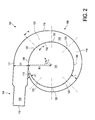
Figure 2 is a plan view of the contaminant extraction device offigure 1 , -
Figure 3a is a section view along A-A offigure 2 , -
Figure 3b is a perspective view of an insert for the contaminant extraction device offigure 1 , -
Figure 3c is a section view similar tofigure 3a with the insert offigure 3b in-situ, -
Figure 3d is a section view of a second contaminant extraction device in accordance with the present invention, and, -
Figure 3e is a section view of a third contaminant extraction device in accordance with the present invention. -
Figures 1 and2 show acontaminant extraction device 100. Thedevice 100 is in the form of a hollow shell defining aninner chamber 102. The device comprises anoutlet section 104 and apressure chamber section 106. - The
outlet section 104 comprises a cylindricaltubular conduit 108 with acircular outlet 110. Thepressure chamber section 106 is defined by aninner wall 112, atop wall 114, abottom wall 116 and anouter wall 118. The four walls are generally at 90 degrees to each other in cross section so as to define a rectangular cross section as will be described below. - The
pressure chamber section 106 is best described in terms of a radial coordinate system r,θ (where θ is in degrees). - The
inner wall 112 extends from afirst end 111 of thepressure chamber section 106 at r,θ=(R1 , 0) proximate theoutlet section 104. Theinner wall 112 extends to a second,opposite end 113 of thepressure chamber section 106 at r,θ=(R1 , 340). Therefore theinner wall 112 describes a circle segment of radius R1 for a 340 degree circle segment. - The
outer wall 118 also extends from thefirst end 111 to thesecond end 113, and converges towards theinner wall 112 from thefirst end 111 to thesecond end 113. Theouter wall 118 forms a spiral from r,θ =(R1+L1 , 0) to r,θ =(R1+L2 , 340). L2 is less than L1. - In this embodiment, R1 = 200mm, L1 = 64mm, L2 = 8mm. The radial distance between the
inner wall 112 and the outer wall 118 L, reduces proportionally to the angle θ, so:


- Therefore the path of the
outer wall 118 is an involute of the circle prescribed by the circle of theinner wall 112. Theouter wall 118 forms an Archimedian spiral. Thetop wall 114 and thebottom wall 116 are parallel and equally spaced (at 30mm) throughout the length of thepressure chamber section 106. Therefore, the cross sectional area of thepressure chamber section 106 decreases proportionally to the angle θ. - It is beneficial for the spacing between the top and bottom walls (the out-of-plane "height" of the device) to be small to aid visibility and access of the user.
- At discrete positions around the inner perimeter of the
pressure chamber section 106,circular orifices 120 through theinner wall 112 are located (seefigures 1 and3a ). All orifices have the same diameter D. - According to the invention,
inserts 122 are provided as shown infigure 3b . Each insert comprises abase section 124 and aflange 126. Both thebase section 124 and theflange 126 are cylindrical and define a centralaxial bore 128 therethrough. The diameter of thebase section 124 is approximately D. - As shown in
figure 3c , thebase section 124 of theinsert 122 is inserted into theorifice 120 such that theflange 126 abuts theinner wall 112. In this way, the inserts can be changed to adjust the diameter of theorifices 128 to provide the desired pressure distribution. - In use, the
device 100 is connected to a vacuum hose (not shown) via theoutlet section 104. The vacuum hose reduces the pressure in theinner chamber 102 and therefore thepressure chamber section 106. As the pressure in thesection 106 is lower than ambient pressure, air flows into thesection 106 through theorifices 120. Therefore if thedevice 100 is placed around a workpiece (not shown) in adecontamination area 101 such that theinner wall 112 substantially encloses the workpiece, airborne contaminants will be extracted. - Because the device almost completely surrounds the workpiece (i.e. it has a 340 degree perimeter) it is able to remove contaminants regardless of which direction the machine tool ejects them in. From this point of view, it is important that the fluid transfer path into the
section 106 surrounds as much of the workpiece as possible. - The pressure distribution is important as ideally, the flow rate through each of the
orifices 120 should be equal to provide an equal decontamination effect around the workpiece. It will be noted that the sum of the areas of the orifices 120 (or 128 if theinserts 122 are used) is equal to the area of theoutlet orifice 110. - Equal pressure distribution is achieved by the reduction in cross sectional area of the
section 106 with θ. What is important is that the cross-sectional area is progressively smaller at eachorifice 120 moving further away from theoutlet 110. - A further embodiment of the above invention is shown in
figure 3d , in which theorifice 120 has an inwardlycurved flow guide 130, which comprisesradii 132.Figure 3e shows the same principle applied to theinsert 122. - The
device 100 is coloured white, to provide the user with an indication that the contaminant extraction is functioning correctly (carbon fibre residue, for example, is dark and shows up). - Variations of the above embodiments fall within the scope of the present invention.
- The
discrete orifices 120 may be a continuous orifice around the inner perimeter of thepressure chamber section 106. The orifice may be a constant height slit or may vary in height. - The path of the
inner wall 112 may be any shape capable of at least partially surrounding a workpiece, and may be tailored to the outer profile of a given workpiece. For example the path may be polygonal (e.g. square, rectangular etc.) or otherwise curved (e.g. elliptical). - The device may be made flexible to provide the user with the ability to form the desired shape for the manufacturing process in question.
Claims (15)
- A composite material manufacturing apparatus comprising;
a composite material manufacture machine tool,
an airborne contaminant extractor having a low pressure chamber, a first wall separating the low pressure chamber and an area to be decontaminated, the first wall defining a fluid transfer path therethrough for fluid communication between the low pressure chamber and the area to be decontaminated, the fluid transfer path facing the area to be decontaminated over an angle range of more than 180 degrees wherein the low pressure chamber comprises a closed first end and a second end connected to a low pressure outlet, in which the cross sectional area of the low pressure chamber increases from the closed end to the low pressure outlet,
in which the machine tool is positioned to be at least partially within the area to be decontaminated. - A composite material manufacturing apparatus according to claim 1 in which the extractor comprises a second wall at least partially defining the low pressure chamber, in which the second wall converges towards the first wall as the low pressure chamber extends away from the outlet.
- A composite material manufacturing apparatus according to claim 3 in which the second wall describes an involute curve of the first wall.
- A composite material manufacturing apparatus according to any preceding claim in which the fluid transfer path comprises a plurality of orifices defined in the first wall.
- A composite material manufacturing apparatus according to claim 4 in which the plurality of orifices comprises:a first orifice having a first axis perpendicular to a plane of the first orifice, and,a second orifice having a second axis perpendicular to a plane of the second orifice,in which the first and second axes are aparallel.
- A composite material manufacturing apparatus according to any preceding claim comprising an orifice defined in the first wall, wherein the apparatus comprises a removable insert received in the orifice, the insert defining an insert orifice therethrough, the insert orifice defining the fluid transfer path.
- A composite material manufacturing apparatus according to any preceding claim in which the at least the first wall of the extractor is flexible to selectively alter the area for decontamination.
- A composite material manufacturing apparatus according to claim 7 in which the extractor is constructed from a flexible material.
- A composite material manufacturing apparatus according to claim 5 in which the first and second axes converge at a position on the side of the first wall of the area to be decontaminated.
- A composite material manufacturing apparatus according to any preceding claim in which the first wall is curved.
- A composite material manufacturing apparatus according to claim 10 in which the first wall describes a circle segment.
- A composite material manufacturing apparatus according to any preceding claim in which the fluid transfer path comprises a plurality of equally spaced orifices around the circumference of the first wall.
- A composite material manufacturing apparatus according to any preceding claim in which the fluid transfer path is defined in the wall to face the area to be decontaminated over an angle range of at least 270 degrees.
- A composite material manufacturing apparatus according to claim 13 in which the fluid transfer path is defined in the wall to face the area to be decontaminated over an angle range of at least 330 degrees.
- A method of manufacturing a composite material component comprising the steps of:providing a composite material manufacture machine tool,providing a composite workpiece,providing a low pressure chamber extending from a low pressure outlet, the low pressure chamber having a wall between the low pressure chamber and a work area defining a fluid transfer path therethrough, the fluid transfer path facing the area to be decontaminated over an angle range of more than 180 degrees wherein the low pressure chamber comprises a closed first end and a second end connected to a low pressure outlet, in which the cross sectional area of the low pressure chamber increases from the closed end to the low pressure outlet,,applying the tool to the workpiece at least partially within the work area,reducing the pressure at the low pressure outlet to extract contaminants from the work area through the fluid transfer path.
Applications Claiming Priority (1)
| Application Number | Priority Date | Filing Date | Title |
|---|---|---|---|
| GBGB0910899.4A GB0910899D0 (en) | 2009-06-24 | 2009-06-24 | Contaminant extraction apparatus |
Publications (2)
| Publication Number | Publication Date |
|---|---|
| EP2266756A2 true EP2266756A2 (en) | 2010-12-29 |
| EP2266756A3 EP2266756A3 (en) | 2013-09-11 |
Family
ID=40972706
Family Applications (1)
| Application Number | Title | Priority Date | Filing Date |
|---|---|---|---|
| EP10165893.8A Withdrawn EP2266756A3 (en) | 2009-06-24 | 2010-06-14 | Contaminant extraction apparatus |
Country Status (3)
| Country | Link |
|---|---|
| US (1) | US20100330893A1 (en) |
| EP (1) | EP2266756A3 (en) |
| GB (1) | GB0910899D0 (en) |
Cited By (1)
| Publication number | Priority date | Publication date | Assignee | Title |
|---|---|---|---|---|
| CN103934141A (en) * | 2014-03-19 | 2014-07-23 | 常州神力热喷涂技术有限公司 | Dust collecting device for rod part spraying operation and fan dust collecting opening thereof |
Families Citing this family (4)
| Publication number | Priority date | Publication date | Assignee | Title |
|---|---|---|---|---|
| US12207863B2 (en) | 2015-10-29 | 2025-01-28 | Innoblative Designs, Inc. | Screen sphere tissue ablation devices and methods |
| EP3538000A4 (en) | 2016-11-08 | 2020-04-01 | Innoblative Designs, Inc. | Electrosurgical tissue and vessel sealing device |
| WO2019023328A1 (en) | 2017-07-26 | 2019-01-31 | Innoblative Designs, Inc. | Minimally invasive articulating assembly having ablation capabilities |
| US12527622B2 (en) | 2021-04-26 | 2026-01-20 | Innoblative Designs, Inc. | System for minimally invasive tissue ablation and sealing |
Family Cites Families (34)
| Publication number | Priority date | Publication date | Assignee | Title |
|---|---|---|---|---|
| US3099965A (en) * | 1958-01-02 | 1963-08-06 | Krantz H Fa | Jet conveyors |
| US3167260A (en) * | 1960-12-23 | 1965-01-26 | Gen Dynamics Corp | Chip collection and disposal apparatus |
| AU472778B2 (en) * | 1973-06-08 | 1976-06-03 | Clarkson Industries Inc | Dust collector for portable rotary disc grinder |
| DE2603330C2 (en) * | 1976-01-29 | 1986-09-04 | Norbert 6109 Mühltal Loevenich | Device for removing cuttings, drilling dust and the like, especially with hand drills during the drilling process |
| US4340326A (en) * | 1980-02-25 | 1982-07-20 | Cooper Industries, Inc. | Broken bit detector |
| US4296523A (en) * | 1980-03-31 | 1981-10-27 | Chevron Research Company | Dust-collection head for a dust collection system |
| US5215539A (en) * | 1988-10-12 | 1993-06-01 | Schoolman Scientific Corporation | Vacuum strip apparatus for surgery |
| US5173030A (en) * | 1988-10-27 | 1992-12-22 | Klockner Oecotec Gmbh | Jet pipe |
| US5211639A (en) * | 1990-05-30 | 1993-05-18 | Wilk Peter J | Evacuator assembly |
| USD334330S (en) * | 1991-01-25 | 1993-03-30 | Horst Moshammer | Dust collector for a grinder |
| DE4234538C1 (en) * | 1992-10-14 | 1994-04-14 | Herbst Bremer Goldschlaegerei | Device for extracting gases, especially those containing dust |
| US5632579A (en) * | 1994-07-13 | 1997-05-27 | Thermwood Corporation | Particulate removal device and system for router machines and the like |
| US5762691A (en) * | 1995-03-21 | 1998-06-09 | Sikorsky Aircraft Corporation | Aerodynamic-electrostatic particulate collection system |
| US5768740A (en) * | 1995-05-16 | 1998-06-23 | Sandia Corporation | Debris exhaust system |
| DE19543599B4 (en) * | 1995-11-23 | 2007-01-25 | Vorwerk & Co. Interholding Gmbh | Extraction device for drilling dust resulting from drilling |
| EP0813464B1 (en) * | 1996-01-04 | 1999-07-21 | British Aerospace Public Limited Company | Debris removal |
| US6942650B1 (en) * | 1998-04-17 | 2005-09-13 | Innovative Surgical Technologies, Inc. | Evacuator |
| US5988954A (en) * | 1999-01-12 | 1999-11-23 | The Boeing Company | Vacuum attachment for power tool |
| US6171407B1 (en) * | 1999-10-12 | 2001-01-09 | Motorola, Inc. | Ventilation fixture and method of using same |
| US6279197B1 (en) * | 2000-01-06 | 2001-08-28 | Rotobrush | Ductwork cleaning system |
| US7024723B2 (en) * | 2001-06-15 | 2006-04-11 | Headwaters R&D, Inc. | Duster cleaning member for a vacuum cleaner |
| US6830113B2 (en) * | 2002-07-17 | 2004-12-14 | Ohio State Home Services | Dust suppression guard |
| GB0305846D0 (en) * | 2003-03-14 | 2003-04-16 | Black & Decker Inc | Dust extraction shrould for a power tool |
| US7160063B2 (en) * | 2003-10-24 | 2007-01-09 | The Boeing Company | Coolant feed drill nozzle with thrust-vectored exhaust |
| JP2006192525A (en) * | 2005-01-12 | 2006-07-27 | Miyanaga:Kk | Dust collector for drilling tool |
| US7044843B1 (en) * | 2005-05-09 | 2006-05-16 | Kun Yi Lin | Sander device having vacuuming structure |
| US20070209144A1 (en) * | 2006-03-10 | 2007-09-13 | Bissell Homecare, Inc. | Vacuum cleaner with improved hygenic performance |
| US7465132B2 (en) * | 2006-08-08 | 2008-12-16 | Dale Gipson | Vacuum dust collector brush assembly |
| US7837411B2 (en) * | 2006-11-17 | 2010-11-23 | Krouse Wayne F | Methods and apparatus for improved hydropower system |
| US7905260B2 (en) * | 2008-01-12 | 2011-03-15 | Richard Keenan | Router dust collection assembly |
| US20090181606A1 (en) * | 2008-01-15 | 2009-07-16 | Michael Loveless | Vacuum shroud for use with drilling tools |
| DE202008008561U1 (en) * | 2008-06-19 | 2008-09-04 | Electrostar Schöttle GmbH & Co. KG | Apparatus for extracting cuttings during drilling by means of a drill in masonry and the like. |
| US8533907B2 (en) * | 2009-01-06 | 2013-09-17 | Emerson Electric Co. | Flexible crevice tool attachment for vacuum appliances |
| US8079389B2 (en) * | 2009-01-28 | 2011-12-20 | Shepherd Daryl E | Vacuum attachment for router table |
-
2009
- 2009-06-24 GB GBGB0910899.4A patent/GB0910899D0/en not_active Ceased
-
2010
- 2010-06-14 EP EP10165893.8A patent/EP2266756A3/en not_active Withdrawn
- 2010-06-17 US US12/801,628 patent/US20100330893A1/en not_active Abandoned
Non-Patent Citations (1)
| Title |
|---|
| None |
Cited By (1)
| Publication number | Priority date | Publication date | Assignee | Title |
|---|---|---|---|---|
| CN103934141A (en) * | 2014-03-19 | 2014-07-23 | 常州神力热喷涂技术有限公司 | Dust collecting device for rod part spraying operation and fan dust collecting opening thereof |
Also Published As
| Publication number | Publication date |
|---|---|
| EP2266756A3 (en) | 2013-09-11 |
| GB0910899D0 (en) | 2009-08-05 |
| US20100330893A1 (en) | 2010-12-30 |
Similar Documents
| Publication | Publication Date | Title |
|---|---|---|
| US20100330893A1 (en) | Contaminant extraction apparatus | |
| US6200075B1 (en) | Drill motor vacuum attachment | |
| US4245437A (en) | Rotary tool suction housing | |
| EP2490614B1 (en) | Nozzle for blasting liquid detergents with dispersed abrasive particles | |
| US8702478B2 (en) | Angle grinder dust shroud with unitary adjustable mounting collar | |
| KR102283979B1 (en) | High-pressure waterjet cutting head systems, components and related methods | |
| JP6165974B2 (en) | Vacuum drilling system and method | |
| US20200078893A1 (en) | Machine tool | |
| EP3576905A1 (en) | Accessory device for a hand-held power tool | |
| US20120058711A1 (en) | Blasting apparatus and method for blast processing | |
| EP3240653B1 (en) | Dust extraction device | |
| EP3781353B1 (en) | Abrasive fluid jet cutting head and related method for cutting sensitive materials | |
| DE69603355T2 (en) | WASTE DISPOSAL | |
| US20140352155A1 (en) | Hand-held electric power tool with a suction adapter | |
| EP3047940A1 (en) | Device for suctioning off grinding dust on rotation grinders | |
| DE10156387A1 (en) | Hand machine tool with air inlet or outlet openings in the housing | |
| WO2010052031A1 (en) | A process turning disc, a robot arm comprising a process turning disc, a robot and a use of a process turning disc | |
| WO2012045399A1 (en) | Abrasive cutting-off device with dust extraction | |
| DE102004035875B3 (en) | Drill apparatus for mineral materials, has air guide system, particle separator, and air generator supported on drill device to form hand-held unit | |
| JP2011212789A (en) | Dust collection case for machine tool | |
| KR20200000813U (en) | Filtering Device for cutting oil | |
| KR20150127318A (en) | Air Knife Having Ring Shape | |
| US6431470B2 (en) | Low-noise air nozzle | |
| DE10255747A1 (en) | Laser for processing especially inscribing workpiece surfaces has gas pressure sensor to determine pressure difference between radiation volume and surroundings | |
| EP3332910A1 (en) | Dust hood for a grinding device |
Legal Events
| Date | Code | Title | Description |
|---|---|---|---|
| PUAI | Public reference made under article 153(3) epc to a published international application that has entered the european phase |
Free format text: ORIGINAL CODE: 0009012 |
|
| AK | Designated contracting states |
Kind code of ref document: A2 Designated state(s): AL AT BE BG CH CY CZ DE DK EE ES FI FR GB GR HR HU IE IS IT LI LT LU LV MC MK MT NL NO PL PT RO SE SI SK SM TR |
|
| AX | Request for extension of the european patent |
Extension state: BA ME RS |
|
| PUAL | Search report despatched |
Free format text: ORIGINAL CODE: 0009013 |
|
| AK | Designated contracting states |
Kind code of ref document: A3 Designated state(s): AL AT BE BG CH CY CZ DE DK EE ES FI FR GB GR HR HU IE IS IT LI LT LU LV MC MK MT NL NO PL PT RO SE SI SK SM TR |
|
| AX | Request for extension of the european patent |
Extension state: BA ME RS |
|
| RIC1 | Information provided on ipc code assigned before grant |
Ipc: B23Q 11/00 20060101AFI20130808BHEP Ipc: B24B 55/06 20060101ALI20130808BHEP Ipc: B23B 47/34 20060101ALI20130808BHEP |
|
| 17P | Request for examination filed |
Effective date: 20140228 |
|
| RBV | Designated contracting states (corrected) |
Designated state(s): AL AT BE BG CH CY CZ DE DK EE ES FI FR GB GR HR HU IE IS IT LI LT LU LV MC MK MT NL NO PL PT RO SE SI SK SM TR |
|
| GRAP | Despatch of communication of intention to grant a patent |
Free format text: ORIGINAL CODE: EPIDOSNIGR1 |
|
| RIC1 | Information provided on ipc code assigned before grant |
Ipc: B23Q 11/00 20060101AFI20140826BHEP Ipc: B24B 55/06 20060101ALI20140826BHEP Ipc: B23B 47/34 20060101ALI20140826BHEP |
|
| INTG | Intention to grant announced |
Effective date: 20140923 |
|
| RIN1 | Information on inventor provided before grant (corrected) |
Inventor name: RIVERA, LUIS Inventor name: TURNER, CHRISTOPHER |
|
| STAA | Information on the status of an ep patent application or granted ep patent |
Free format text: STATUS: THE APPLICATION IS DEEMED TO BE WITHDRAWN |
|
| 18D | Application deemed to be withdrawn |
Effective date: 20150408 |