EP2266443A1 - Flexible checkout with possibility of rapid and simplified conversion from normal assisted use to self-checkout use and vice versa - Google Patents
Flexible checkout with possibility of rapid and simplified conversion from normal assisted use to self-checkout use and vice versa Download PDFInfo
- Publication number
- EP2266443A1 EP2266443A1 EP10166131A EP10166131A EP2266443A1 EP 2266443 A1 EP2266443 A1 EP 2266443A1 EP 10166131 A EP10166131 A EP 10166131A EP 10166131 A EP10166131 A EP 10166131A EP 2266443 A1 EP2266443 A1 EP 2266443A1
- Authority
- EP
- European Patent Office
- Prior art keywords
- checkout
- tray
- self
- frame
- mode
- Prior art date
- Legal status (The legal status is an assumption and is not a legal conclusion. Google has not performed a legal analysis and makes no representation as to the accuracy of the status listed.)
- Granted
Links
Images

Classifications
-
- A—HUMAN NECESSITIES
- A47—FURNITURE; DOMESTIC ARTICLES OR APPLIANCES; COFFEE MILLS; SPICE MILLS; SUCTION CLEANERS IN GENERAL
- A47F—SPECIAL FURNITURE, FITTINGS, OR ACCESSORIES FOR SHOPS, STOREHOUSES, BARS, RESTAURANTS OR THE LIKE; PAYING COUNTERS
- A47F9/00—Shop, bar, bank or like counters
- A47F9/02—Paying counters
- A47F9/04—Check-out counters, e.g. for self-service stores
Definitions
- the invention relates to checkouts used in supermarkets and other commercial premises, through which the customer is required to pass to identify and pay for the acquired goods.
- the traditional checkout was designed to handle both large amounts carried in trolleys and small amounts carried in baskets.
- the checkout is usually composed of three modules and comprises in succession a first unit formed by a horizontal conveyor belt on which the customer places the acquired goods, an intermediate unit, usually assisted on the inside by an assistant, where the traditional hardware is a scanner, a till, a printer, a keypad for electronic payments and a cash drawer for cash payments, and an end unit with a tray in which the assistant can deposit the scanned products and from which the customer bags the acquired products.
- the traditional checkout reaches its maximum throughput capacity, since it allows simultaneous placing of goods on the belt and bagging of the goods by the customer.
- self-checkout In addition to the traditional checkouts noted above, there are now also so-called "self-checkout” systems, where it is the customer himself or herself who identifies and pays for the acquired goods.
- the most common self-checkouts still consist of three modules but are used to purchase a limited number of items, such as a maximum of twenty-five items, and for this purpose they have a unit for placing the basket in place of the initial conveyor belt and have a bagging unit in place of the tray.
- the dimensions of the intermediate scanning and payment unit are designed for use by a person on foot, the unit having a touch screen for the interface with the customer and automatic devices for cash and electronic payments.
- the bagging unit may optionally be equipped with checking scales to check that the bagged item corresponds to the scanned item.
- the layout of self-checkouts typically requires the installation of these machines in blocks of four units monitored by a roving assistant who keeps an eye on things and gives assistance.
- This kind of convertible checkout according to the invention would have the aim of offering customers better service, giving greater flexibility in the use of the row of checkouts, and allow a reduction in staffing costs without reducing the throughput capacity of said row of checkouts.
- Such a checkout would be particularly suitable for points of sale that do not have a large number of checkouts, in which there must be some assisted checkouts, and in which there is often a need to cover time periods frequented by customers who purchase only a few products, who are in a hurry, and for which it is not financially justifiable to open another assisted checkout.
- the invention provides an easily and quickly convertible checkout that can be set up to be used mostly in the self-checkout mode but which on occasion can easily and quickly be converted into a checkout for use in "assisted" mode at peak times and/or timeslots and/or situations in which it is judged suitable and remunerative to also offer the customer human contact with an assistant.
- the convertible checkout which imitates a traditional layout, should not have connections to the installed units and could, especially at small points of sale, have remote monitoring by an operator who intervenes if necessary and with assisted tills or other devices (video cameras, automatic exit gates) for theft deterrence.
- the invention provides for said intermediate scanning unit to be used by an assistant (assisted use mode), or, on the same side as that used by the assistant, directly by the customer (self-checkout use mode), neutralizing in the latter case the architectural volume occupied by the end tray where the goods are collected, by displacing this unit by rotation or pivoting and/or by a translational movement, in such a way as to create downstream of said intermediate unit enough free space to allow the customer to comfortably bag his or her acquired goods previously identified by the scanner.
- assistant assisted use mode
- self-checkout use mode neutralizing in the latter case the architectural volume occupied by the end tray where the goods are collected
- the customer places the products on the initial conveyor belt, reads the barcode of each product at the intermediate unit, where a dedicated software interface will be available for use of the checkout in self-checkout mode, for payment and other purposes, and bags said products in the end space which is now not taken up by the tray.
- references B1, B2 and B3 are three identical checkouts of the present type, arranged side by side and parallel with each other to form the exit barrier from the point of sale, through which customers must pass in order to pay for their acquired goods.
- Each checkout comprises an initial conveyor belt T, which is horizontal and usually motorized, on which the customer places the acquired goods; an intermediate unit C with scanner, till, printer, an automatic device for cash payments, a keypad for electronic payments and a touch screen interface for use in both assisted and self-checkout modes; and an end tray V which in the present example is of the wide type, with an intermediate dividing pivoting bar P for dividing the tray into two parts, although it can be of any suitable type.
- the drive to the conveyor belt T is usually stopped by a photoelectric cell positioned in a known manner upstream of the intermediate unit C.
- the checkouts B1 and B3 are shown in the assisted use mode, with an assistant CS sitting at the intermediate unit C with his or her cash drawer in the dedicated space of this unit C.
- the assistant occupies a space bounded on the left by part of the tray V, in front by the unit C, and on the right by a unit M which may stand on wheels or runners or which may be connected laterally to the frame of the conveyor belt, with the option of being swung out of the way and in front of which a pre-checkout display E may be located, as shown next to the checkout B3.
- the unit M may be absent, leaving the space required for the assistant's effects in retractable drawers in the forward leg of the supporting frame.
- the intermediate checkout B2 unlike checkouts B1 and B3, is shown in the self-checkout use mode, to which it has been converted by the following rapid sequence of operations:
- Figures 3 and 4 show that in one possible embodiment the end tray V is housed in a frame 1 with handholds 2 on the longitudinal sides and which has, in the middle of the transverse sides, mutually aligned integral brackets 3, which may for example be of a C-shaped profile, whose ends outside of the frame 1 are pivoted at 4 to triangular gusset plates 5 attached by their base to the innermost 206 of three telescopic tracks 6, 106, 206, the outermost track of which is attached to the top 107 of a base frame 7 which stands on the floor via a bottom 207 and has at least one cross member 307 interconnecting the two symmetrical parts of the frame.
- the frame 7 is designed for connection to the adjacent parts of the frame of the checkout in any suitable way.
- FIGS 2 and 2a illustrate a variant of the checkout according to the invention, in which the end comprises the V' tray where the goods are collected in the assisted-use mode.
- This tray is not wide as in the previous version.
- a shelf R which forms with the tray a single body connected to the part upstream of the checkout frame, the part with the central unit C, with interposed track and slider means that allow this end unit V'-R to perform a defined horizontal movement of transverse translation such that, when the checkouts are in the assisted position, as at B1 and B3, said tray V' is aligned with the central unit C, whereas when the checkout is in the self-checkout use mode, as illustrated by the intermediate checkout B2, it is the shelf R which is aligned with the central unit C, and the tray V' is in the displaced position and not in use.
- the shelf R may advantageously include a weighing unit which monitors the weight of the purchases so as to check whether the weight does or does not correspond to the weight of the products whose barcodes the customer has read on the scanner
- reference 11 denotes an end part of the frame of the intermediate unit C, which comprises the vertical wall 111 with an intermediate transverse bracket 12, and a bottom transverse bracket 112, both of U profile, the outward flange of each supporting corresponding track and slider assemblies 13, 113.
- Said wall 111 has an integral horizontal bottom extension 211 which stands on the floor via feet (not shown) and which has on the outermost edge another track and slider assembly 213 parallel to the aforementioned assemblies 13, 113.
- the moving part of these track and slider assemblies is connected to the frame 14, which is shaped like two steps, the top step of which carries the horizontal frame 15 for the tray V' and the bottom step of which carries the aforementioned shelf R. Wheels (not illustrated) may be provided at the opposite ends of the moving frame 14 in order to rest on the floor and support that end of this frame which will sometimes project from the fixed supporting walls 111, 211.
- converting the checkout does not require conversions and other interventions on the intermediate unit C containing the electronic parts, thus greatly simplifying its construction and its cost and improving the functional reliability of the entire checkout.
Landscapes
- Cash Registers Or Receiving Machines (AREA)
- Measuring Pulse, Heart Rate, Blood Pressure Or Blood Flow (AREA)
Abstract
Description
- The invention relates to checkouts used in supermarkets and other commercial premises, through which the customer is required to pass to identify and pay for the acquired goods. The traditional checkout was designed to handle both large amounts carried in trolleys and small amounts carried in baskets. The checkout is usually composed of three modules and comprises in succession a first unit formed by a horizontal conveyor belt on which the customer places the acquired goods, an intermediate unit, usually assisted on the inside by an assistant, where the traditional hardware is a scanner, a till, a printer, a keypad for electronic payments and a cash drawer for cash payments, and an end unit with a tray in which the assistant can deposit the scanned products and from which the customer bags the acquired products. In the version with a conveyor belt and a wide tray with a dividing bar, the traditional checkout reaches its maximum throughput capacity, since it allows simultaneous placing of goods on the belt and bagging of the goods by the customer.
- In addition to the traditional checkouts noted above, there are now also so-called "self-checkout" systems, where it is the customer himself or herself who identifies and pays for the acquired goods. The most common self-checkouts still consist of three modules but are used to purchase a limited number of items, such as a maximum of twenty-five items, and for this purpose they have a unit for placing the basket in place of the initial conveyor belt and have a bagging unit in place of the tray. The dimensions of the intermediate scanning and payment unit are designed for use by a person on foot, the unit having a touch screen for the interface with the customer and automatic devices for cash and electronic payments. The bagging unit may optionally be equipped with checking scales to check that the bagged item corresponds to the scanned item. The layout of self-checkouts typically requires the installation of these machines in blocks of four units monitored by a roving assistant who keeps an eye on things and gives assistance.
- Four self-checkout stations occupy roughly the same amount of space as two traditional checkouts and can therefore maintain roughly the same throughput capacity. The main difference is in the type of purchases handled. The most common self-checkouts can only handle purchases of a few products, usually no more than can be carried in one basket, whereas conventional checkouts can handle any type of purchase. The economic advantage of having self-checkouts must therefore be weighed against the lower throughput capacity of the point of sale for an equivalent footprint of the row of checkouts.
- The applicant has observed the lack on the market of a flexible, easily convertible checkout that can give the point of sale the ability to offer the advantages of both the traditional checkout and the self-checkout.
- This kind of convertible checkout according to the invention would have the aim of offering customers better service, giving greater flexibility in the use of the row of checkouts, and allow a reduction in staffing costs without reducing the throughput capacity of said row of checkouts. Such a checkout would be particularly suitable for points of sale that do not have a large number of checkouts, in which there must be some assisted checkouts, and in which there is often a need to cover time periods frequented by customers who purchase only a few products, who are in a hurry, and for which it is not financially justifiable to open another assisted checkout.
- To meet these requirements, the invention provides an easily and quickly convertible checkout that can be set up to be used mostly in the self-checkout mode but which on occasion can easily and quickly be converted into a checkout for use in "assisted" mode at peak times and/or timeslots and/or situations in which it is judged suitable and remunerative to also offer the customer human contact with an assistant.
- The convertible checkout, which imitates a traditional layout, should not have connections to the installed units and could, especially at small points of sale, have remote monitoring by an operator who intervenes if necessary and with assisted tills or other devices (video cameras, automatic exit gates) for theft deterrence.
- The features of the invention are summarized in the accompanying Claim 1 and its dependent claims and are based on the following concept. In a checkout of traditional type, that comprises in operational succession the three aforementioned units - the conveyor belt on which the products are loaded, the intermediate scanning and payment unit, and the end tray where the checked products are collected - the invention provides for said intermediate scanning unit to be used by an assistant (assisted use mode), or, on the same side as that used by the assistant, directly by the customer (self-checkout use mode), neutralizing in the latter case the architectural volume occupied by the end tray where the goods are collected, by displacing this unit by rotation or pivoting and/or by a translational movement, in such a way as to create downstream of said intermediate unit enough free space to allow the customer to comfortably bag his or her acquired goods previously identified by the scanner. When the checkout is being used in self-checkout mode, the customer places the products on the initial conveyor belt, reads the barcode of each product at the intermediate unit, where a dedicated software interface will be available for use of the checkout in self-checkout mode, for payment and other purposes, and bags said products in the end space which is now not taken up by the tray.
- Other features of the invention, and the advantages which it procures, will be made clearer by the following description of certain preferred embodiments of said invention, illustrated purely by way of non-restrictive example in the figures of the accompanying sheets of drawings, in which:
-
Figures 1 and 1 a are a perspective view and a top plan view, respectively, of three checkouts according to the invention, side by side, of the type with conversion by rotation, only one of which is in the self-checkout use mode; -
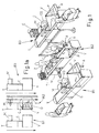
Figures 2 and 2a are a perspective view and a top plan view, respectively, of three checkouts according to the invention, side by side, of the type with conversion by translational movement, only one of these being in the self-checkout use mode; -
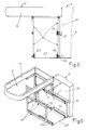
Figures 3 and 4 are a perspective view and a side elevation with parts in section, respectively, of the frame supporting the end tray of the checkout in the conversion by rotation, viewed first in the assisted-use mode and then in the self-checkout use mode of said checkout. -
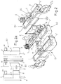
Figures 5 and 6 are a side elevation and a perspective view, respectively, of the frame supporting the end tray of the checkout with conversion by translational movement, viewed in the self-checkout use mode of said checkout. - In
Figures 1 and 1a , references B1, B2 and B3 are three identical checkouts of the present type, arranged side by side and parallel with each other to form the exit barrier from the point of sale, through which customers must pass in order to pay for their acquired goods. Each checkout comprises an initial conveyor belt T, which is horizontal and usually motorized, on which the customer places the acquired goods; an intermediate unit C with scanner, till, printer, an automatic device for cash payments, a keypad for electronic payments and a touch screen interface for use in both assisted and self-checkout modes; and an end tray V which in the present example is of the wide type, with an intermediate dividing pivoting bar P for dividing the tray into two parts, although it can be of any suitable type. The drive to the conveyor belt T is usually stopped by a photoelectric cell positioned in a known manner upstream of the intermediate unit C. - The checkouts B1 and B3 are shown in the assisted use mode, with an assistant CS sitting at the intermediate unit C with his or her cash drawer in the dedicated space of this unit C. The assistant occupies a space bounded on the left by part of the tray V, in front by the unit C, and on the right by a unit M which may stand on wheels or runners or which may be connected laterally to the frame of the conveyor belt, with the option of being swung out of the way and in front of which a pre-checkout display E may be located, as shown next to the checkout B3. In a constructional variant, the unit M may be absent, leaving the space required for the assistant's effects in retractable drawers in the forward leg of the supporting frame. The intermediate checkout B2, unlike checkouts B1 and B3, is shown in the self-checkout use mode, to which it has been converted by the following rapid sequence of operations:
- the end tray V has been rotated through 90° about the longitudinal axis of the checkout, by lifting the portion which previously was next to the assistant and which is now open for the customer Z to pass through;
- the unit M, if present, may have been inserted underneath the conveyor belt T, or may be located at the start of this unit, to support the basket of purchases, while the goods are being extracted from the basket and placed on said conveyor belt;
- in the space freed up by lifting the tray V out of the way, bags are held, while being filled with products, by bag holders mounted on an optional weighing pan to check their weight and thus verify that what has been scanned and bagged is correct. In another variant, bag holding arms A may be located underneath the tray;
- dedicated software for the self-checkout use mode of the checkout is activated so that the customer Z, after placing the goods on the conveyor belt T, can stand next to the intermediate unit C, on the side previously occupied by the assistant, in order to scan the barcodes of the individual acquired goods on his own or her own, before placing them in the bags S. After scanning and bagging them, the customer will work through the payment protocol, which may vary depending on the case. If problems occur during the scanning and bagging phase, help and/or alarm procedures will be activated as appropriate.
-
Figures 3 and 4 show that in one possible embodiment the end tray V is housed in a frame 1 withhandholds 2 on the longitudinal sides and which has, in the middle of the transverse sides, mutually alignedintegral brackets 3, which may for example be of a C-shaped profile, whose ends outside of the frame 1 are pivoted at 4 totriangular gusset plates 5 attached by their base to the innermost 206 of threetelescopic tracks top 107 of abase frame 7 which stands on the floor via abottom 207 and has at least onecross member 307 interconnecting the two symmetrical parts of the frame. Theframe 7 is designed for connection to the adjacent parts of the frame of the checkout in any suitable way. When the tray V is in the horizontal position of use, as inFigure 3 and as shown in chain line inFigure 4 , the system oftracks end brackets 8 withlever arms 9 hinged tobrackets 10 on thecrossmember 307 of thebase frame 7. To avoid unwanted movements of the frame 1 in the condition depicted inFigure 3 , locking means, not shown but easy for a skilled person to devise, may be used. When these optional locking means are neutralized and the frame 1 is pushed in the direction indicated inFigure 3 by arrow F, the frame moves towards thebase frame 7, thetelescopic tracks lever arms 9 and swings up at the opposite end, until it is in the vertical position shown inFigure 4 in solid lines, in which the checkout can be used in the self-checkout mode, as indicated with reference toFigures 1 and 1a . Safety means (not shown) can be provided to lock the frame 1 in theFigure 4 position. -
Figures 2 and 2a illustrate a variant of the checkout according to the invention, in which the end comprises the V' tray where the goods are collected in the assisted-use mode. This tray is not wide as in the previous version. Next to it is a shelf R which forms with the tray a single body connected to the part upstream of the checkout frame, the part with the central unit C, with interposed track and slider means that allow this end unit V'-R to perform a defined horizontal movement of transverse translation such that, when the checkouts are in the assisted position, as at B1 and B3, said tray V' is aligned with the central unit C, whereas when the checkout is in the self-checkout use mode, as illustrated by the intermediate checkout B2, it is the shelf R which is aligned with the central unit C, and the tray V' is in the displaced position and not in use. In this version the shelf R may advantageously include a weighing unit which monitors the weight of the purchases so as to check whether the weight does or does not correspond to the weight of the products whose barcodes the customer has read on the scanner of the central unit. - As regards all the other parts which go to make up the checkout in the version shown in
Figures 2 and 2a and oversee its operation, the same applies to these as applies to the checkout in the version shown inFigures 1 and 1 a. - In
Figures 5 and 6 ,reference 11 denotes an end part of the frame of the intermediate unit C, which comprises thevertical wall 111 with an intermediatetransverse bracket 12, and a bottomtransverse bracket 112, both of U profile, the outward flange of each supporting corresponding track andslider assemblies wall 111 has an integralhorizontal bottom extension 211 which stands on the floor via feet (not shown) and which has on the outermost edge another track andslider assembly 213 parallel to theaforementioned assemblies frame 14, which is shaped like two steps, the top step of which carries thehorizontal frame 15 for the tray V' and the bottom step of which carries the aforementioned shelf R. Wheels (not illustrated) may be provided at the opposite ends of the movingframe 14 in order to rest on the floor and support that end of this frame which will sometimes project from the fixed supportingwalls - In both of the illustrated versions, converting the checkout does not require conversions and other interventions on the intermediate unit C containing the electronic parts, thus greatly simplifying its construction and its cost and improving the functional reliability of the entire checkout.
Claims (9)
- Checkout designed to give flexibility of use to the row of checkouts, with the possibility of rapid and simplified conversion from normal assisted use to self-checkout use and vice versa, of the type that comprises in operational sequence a conveyor belt (T) on which the products are loaded, an intermediate scanning and payment unit (C), and an end tray (V, V') where the checked products are collected, which checkout is characterized in that it comprises means allowing said intermediate unit (C) to be used by the assistant in the assisted mode, or, on the same side as that used by the assistant, directly by the customer in the self-checkout use mode and in that it comprises means which in the latter case allow the actual customer to directly bag the products after the scanning phase, in an area immediately downstream of said intermediate unit (C), from which said tray (V, V') has been moved away, said tray being fitted with means allowing it to be displaced to an out-of-the-way position or completely neutralized to allow the checkout to be used in the self-checkout mode, in which self-checkout mode the customer places the acquired products on the initial conveyor belt (T), reads the barcode of each product at the intermediate unit (C), where a dedicated self-checkout software interface will be available, for payment and other purposes, bags said products in the end space, where the tray is out of the way, and pays the cost of the purchases by any agreed means.
- Checkout according to Claim 1, in which said end tray (V, V') displacing means comprise rotation or pivoting means and/or translational means.
- Checkout according to Claim 2, in which said rotation or pivoting displacing means are such that the tray (V) can also be of the wide type and is supported by means (7) such that from the usual horizontal position said tray can be rotated about a longitudinal axis and simultaneously translated parallel to this axis until it is in an essentially vertical and external position, releasing a large amount of space downstream of the central scanning unit (C), on the side along which the customer is moving, to give the latter good freedom of movement when bagging the goods and when the checkout is being used in the self-checkout mode.
- Checkout according to Claim 3, in which arms (A) may be arranged underneath the tray (V) to hold bags (S) in an open position, facilitating their filling with the goods acquired by the customer when the customer is using the checkout in the self-checkout mode.
- Checkout according to Claim 3, in which the tray (V) is housed in a supporting frame (1) which is fitted, in the middle of the transverse sides, with mutually aligned brackets (3), whose ends outside of said frame are pivoted to gusset plates (5) attached to the innermost (206) of three telescopic tracks (6, 106, 206), the outermost track of which is attached to the top (107) of a supporting frame (7), which stands on the floor via a bottom (207), with at least one crossmember (307) interconnecting the two symmetrical parts of the frame which is designed for connection to the adjacent parts of the frame of the checkout, the arrangement being such that when the tray (V) is in the horizontal position of use, said system of tracks (6, 106, 206) is in the position of maximum extension and the frame (1) is kept horizontal by the articulation of its end lugs (8) with lever arms (9) hinged to brackets (10) on the crossmember (307) of said supporting frame (7); the whole being such that when the frame (1) with the tray is pushed in the transverse direction away from the space which is required to be free for use of the checkout in the self-checkout mode, said frame (1) moves towards its supporting frame (7), the telescopic tracks (6, 106, 206) gradually retract into each other, all inside the fixed track (6), while said frame with the tray swings down at the end connected to said lever arms (9) and up at the opposite end, until it is in the out-of-the-way position in which the checkout can be used in the self-checkout mode.
- Checkout according to Claim 2, in which said translational displacing means have the tray (V') housed in a supporting frame connected to the adjacent frame of the central until (C) by means of transverse displacement tracks (13, 113, 213), so that from the position of alignment with this central unit, for use in the assisted mode, said tray (V') can be moved out translationally to free up a large amount of space downstream of the central scanning unit (C), on the side along which the customer is moving, to give the latter good freedom of movement when bagging the products during the use of the checkout in the self-checkout mode.
- Checkout according to Claim 6, in which a shelf (R) may be located on the same frame which carries the tray (V'), at the side of this tray and of the same height as, or preferably lower than, said tray, so that when the checkout is in the self-checkout use mode, this shelf is downstream of and in line with the central scanning unit (C) and can usefully be used to hold the bags when the customer is filling them with the acquired goods.
- Checkout according to Claim 7, in which the end part of the frame (11) of the intermediate scanning unit (C) comprises a vertical wall (111) with a lower horizontal extension (211), on which walls there are mounted, by means of transverse brackets (12, 112) and partly directly, track and slider assemblies (13, 113, 213) in which the moving part is connected to a stepped frame (14), the top step of which carries the horizontal frame (15) for the tray (V') and the bottom step of which carries said shelf (R), it being possible for wheels to be fitted underneath the opposite ends of said moving frame (14) in order to rest on the floor and support that part of this frame which will sometimes project away from said fixed supporting walls (111, 211).
- Checkout according to claim 1, characterized in that it comprises optional weighing means in combination with the means supporting the bags in the final filling phase during the self-checkout use mode, in order to check electronically whether the weight of the goods acquired does or does not correspond to the weight of the products whose barcodes the customer has read on the scanner of the central unit (C) and these weighing means are connected operationally to the central processing unit to enable or disable the final phase of paying for the purchases depending on whether there is or is not, respectively, equivalence between said two weights, an alarm being set off in the latter case.
Applications Claiming Priority (1)
| Application Number | Priority Date | Filing Date | Title |
|---|---|---|---|
| ITBO2009A000409A IT1394378B1 (en) | 2009-06-24 | 2009-06-24 | FLEXIBLE CASE BENCH, WITH POSSIBILITY OF FAST TRANSFORMATION AND SIMPLIFIED BY NORMAL USE ASSISTED TO THE SELF AND VICE VERSA one. |
Publications (2)
| Publication Number | Publication Date |
|---|---|
| EP2266443A1 true EP2266443A1 (en) | 2010-12-29 |
| EP2266443B1 EP2266443B1 (en) | 2018-02-14 |
Family
ID=42237189
Family Applications (1)
| Application Number | Title | Priority Date | Filing Date |
|---|---|---|---|
| EP10166131.2A Active EP2266443B1 (en) | 2009-06-24 | 2010-06-16 | Flexible checkout with possibility of rapid and simplified conversion from normal assisted use to self-checkout use and vice versa |
Country Status (4)
| Country | Link |
|---|---|
| EP (1) | EP2266443B1 (en) |
| ES (1) | ES2663293T3 (en) |
| IT (1) | IT1394378B1 (en) |
| RU (1) | RU2541942C2 (en) |
Cited By (2)
| Publication number | Priority date | Publication date | Assignee | Title |
|---|---|---|---|---|
| US9275382B2 (en) | 2014-07-25 | 2016-03-01 | Toshiba Global Commerce Solutions Holdings Corporation | Reconfigurable checkout station |
| EP2995225A1 (en) * | 2014-09-12 | 2016-03-16 | HMY Group | Hybrid checkout station for a retail store, comprising a moving system configured to displace said station between a first position and a second position |
Families Citing this family (1)
| Publication number | Priority date | Publication date | Assignee | Title |
|---|---|---|---|---|
| DE202024106987U1 (en) | 2024-12-02 | 2025-01-09 | ITAB Germany GmbH | checkout counter with movable conveyor belt frame |
Citations (2)
| Publication number | Priority date | Publication date | Assignee | Title |
|---|---|---|---|---|
| US3990540A (en) * | 1975-09-04 | 1976-11-09 | Ncr Corporation | Checkout system |
| WO2009033988A1 (en) * | 2007-09-13 | 2009-03-19 | Cefla Societa' Cooperativa | Apparatus for sorting alternately the purchased products into one of the two areas of the usually splayed end part of a checkout counter |
Family Cites Families (3)
| Publication number | Priority date | Publication date | Assignee | Title |
|---|---|---|---|---|
| US2317438A (en) * | 1940-03-22 | 1943-04-27 | Herbert N Bradley | Checking station for self-service stores |
| US6409081B1 (en) * | 1999-11-02 | 2002-06-25 | Ncr Corporation | Apparatus and method for operating a checkout system having an item set-aside shelf which is movable between a number of shelf positions |
| RU36073U1 (en) * | 2003-11-21 | 2004-02-27 | Закрытое акционерное общество Производственное объединение "Витрина" | Settlement and cash box for customer service |
-
2009
- 2009-06-24 IT ITBO2009A000409A patent/IT1394378B1/en active
-
2010
- 2010-06-16 ES ES10166131.2T patent/ES2663293T3/en active Active
- 2010-06-16 EP EP10166131.2A patent/EP2266443B1/en active Active
- 2010-06-23 RU RU2010125816/12A patent/RU2541942C2/en active
Patent Citations (2)
| Publication number | Priority date | Publication date | Assignee | Title |
|---|---|---|---|---|
| US3990540A (en) * | 1975-09-04 | 1976-11-09 | Ncr Corporation | Checkout system |
| WO2009033988A1 (en) * | 2007-09-13 | 2009-03-19 | Cefla Societa' Cooperativa | Apparatus for sorting alternately the purchased products into one of the two areas of the usually splayed end part of a checkout counter |
Cited By (2)
| Publication number | Priority date | Publication date | Assignee | Title |
|---|---|---|---|---|
| US9275382B2 (en) | 2014-07-25 | 2016-03-01 | Toshiba Global Commerce Solutions Holdings Corporation | Reconfigurable checkout station |
| EP2995225A1 (en) * | 2014-09-12 | 2016-03-16 | HMY Group | Hybrid checkout station for a retail store, comprising a moving system configured to displace said station between a first position and a second position |
Also Published As
| Publication number | Publication date |
|---|---|
| RU2010125816A (en) | 2011-12-27 |
| RU2541942C2 (en) | 2015-02-20 |
| ES2663293T3 (en) | 2018-04-11 |
| ITBO20090409A1 (en) | 2010-12-25 |
| EP2266443B1 (en) | 2018-02-14 |
| IT1394378B1 (en) | 2012-06-15 |
Similar Documents
| Publication | Publication Date | Title |
|---|---|---|
| US7967112B2 (en) | Check stand with a two belted input and a slidable scanner | |
| US4373611A (en) | Conveyor to interfit with a loaded shopping cart and to move portions of the load, on demand of a checker, to the front of the cart, for removal, price scanning, and bagging, by the checker at a checkout stand | |
| US8240563B2 (en) | Self checkout stands | |
| EP2266443B1 (en) | Flexible checkout with possibility of rapid and simplified conversion from normal assisted use to self-checkout use and vice versa | |
| US2596686A (en) | Checking station for self-service stores | |
| US20070138269A1 (en) | Self-service checkout system | |
| US5316107A (en) | Device for checking out goods | |
| EP1180463A1 (en) | Shopping trolley | |
| US4182433A (en) | Convertible single-double belt check-out counter | |
| US4265336A (en) | Convertible single-double belt check-out counter | |
| US3797861A (en) | Check out system and cart therefor | |
| US12387252B2 (en) | Self-checkout store | |
| JP3142996U (en) | Cash register counter table and register fixture system using the same | |
| US3480114A (en) | Merchandise check out system | |
| US3700074A (en) | Check out system | |
| JPH0455694B2 (en) | ||
| US20140033957A1 (en) | Self Scan Checkout Module | |
| US5027924A (en) | Cashier check-out station with package-catching shopping cart | |
| JP3140821U (en) | Checkout device, shopping cart, shopping cart and checkout counter | |
| EP2875756B1 (en) | Checkout counter with a basket lifting system | |
| US3739878A (en) | Grocery cart and checkout counter combination | |
| JP3152848U (en) | Accounting stand that can be settled with the basket on the cart | |
| EP2995225B1 (en) | Hybrid checkout station for a retail store, comprising a moving system configured to displace said station between a first position and a second position | |
| CN216943606U (en) | Self-service shopping checkout device for supermarket | |
| JP2745105B2 (en) | Checkout device |
Legal Events
| Date | Code | Title | Description |
|---|---|---|---|
| PUAI | Public reference made under article 153(3) epc to a published international application that has entered the european phase |
Free format text: ORIGINAL CODE: 0009012 |
|
| AK | Designated contracting states |
Kind code of ref document: A1 Designated state(s): AL AT BE BG CH CY CZ DE DK EE ES FI FR GB GR HR HU IE IS IT LI LT LU LV MC MK MT NL NO PL PT RO SE SI SK SM TR |
|
| AX | Request for extension of the european patent |
Extension state: BA ME RS |
|
| 17P | Request for examination filed |
Effective date: 20110615 |
|
| 17Q | First examination report despatched |
Effective date: 20160503 |
|
| GRAP | Despatch of communication of intention to grant a patent |
Free format text: ORIGINAL CODE: EPIDOSNIGR1 |
|
| INTG | Intention to grant announced |
Effective date: 20170913 |
|
| GRAS | Grant fee paid |
Free format text: ORIGINAL CODE: EPIDOSNIGR3 |
|
| GRAA | (expected) grant |
Free format text: ORIGINAL CODE: 0009210 |
|
| AK | Designated contracting states |
Kind code of ref document: B1 Designated state(s): AL AT BE BG CH CY CZ DE DK EE ES FI FR GB GR HR HU IE IS IT LI LT LU LV MC MK MT NL NO PL PT RO SE SI SK SM TR |
|
| AX | Request for extension of the european patent |
Extension state: RS |
|
| REG | Reference to a national code |
Ref country code: GB Ref legal event code: FG4D |
|
| REG | Reference to a national code |
Ref country code: CH Ref legal event code: EP |
|
| REG | Reference to a national code |
Ref country code: IE Ref legal event code: FG4D |
|
| REG | Reference to a national code |
Ref country code: DE Ref legal event code: R096 Ref document number: 602010048449 Country of ref document: DE Ref country code: AT Ref legal event code: REF Ref document number: 969318 Country of ref document: AT Kind code of ref document: T Effective date: 20180315 |
|
| REG | Reference to a national code |
Ref country code: ES Ref legal event code: FG2A Ref document number: 2663293 Country of ref document: ES Kind code of ref document: T3 Effective date: 20180411 |
|
| REG | Reference to a national code |
Ref country code: FR Ref legal event code: PLFP Year of fee payment: 9 |
|
| REG | Reference to a national code |
Ref country code: NL Ref legal event code: MP Effective date: 20180214 |
|
| REG | Reference to a national code |
Ref country code: AT Ref legal event code: MK05 Ref document number: 969318 Country of ref document: AT Kind code of ref document: T Effective date: 20180214 |
|
| PG25 | Lapsed in a contracting state [announced via postgrant information from national office to epo] |
Ref country code: FI Free format text: LAPSE BECAUSE OF FAILURE TO SUBMIT A TRANSLATION OF THE DESCRIPTION OR TO PAY THE FEE WITHIN THE PRESCRIBED TIME-LIMIT Effective date: 20180214 Ref country code: HR Free format text: LAPSE BECAUSE OF FAILURE TO SUBMIT A TRANSLATION OF THE DESCRIPTION OR TO PAY THE FEE WITHIN THE PRESCRIBED TIME-LIMIT Effective date: 20180214 Ref country code: NO Free format text: LAPSE BECAUSE OF FAILURE TO SUBMIT A TRANSLATION OF THE DESCRIPTION OR TO PAY THE FEE WITHIN THE PRESCRIBED TIME-LIMIT Effective date: 20180514 Ref country code: NL Free format text: LAPSE BECAUSE OF FAILURE TO SUBMIT A TRANSLATION OF THE DESCRIPTION OR TO PAY THE FEE WITHIN THE PRESCRIBED TIME-LIMIT Effective date: 20180214 Ref country code: LT Free format text: LAPSE BECAUSE OF FAILURE TO SUBMIT A TRANSLATION OF THE DESCRIPTION OR TO PAY THE FEE WITHIN THE PRESCRIBED TIME-LIMIT Effective date: 20180214 Ref country code: CY Free format text: LAPSE BECAUSE OF FAILURE TO SUBMIT A TRANSLATION OF THE DESCRIPTION OR TO PAY THE FEE WITHIN THE PRESCRIBED TIME-LIMIT Effective date: 20180214 |
|
| PG25 | Lapsed in a contracting state [announced via postgrant information from national office to epo] |
Ref country code: BG Free format text: LAPSE BECAUSE OF FAILURE TO SUBMIT A TRANSLATION OF THE DESCRIPTION OR TO PAY THE FEE WITHIN THE PRESCRIBED TIME-LIMIT Effective date: 20180514 Ref country code: GR Free format text: LAPSE BECAUSE OF FAILURE TO SUBMIT A TRANSLATION OF THE DESCRIPTION OR TO PAY THE FEE WITHIN THE PRESCRIBED TIME-LIMIT Effective date: 20180515 Ref country code: SE Free format text: LAPSE BECAUSE OF FAILURE TO SUBMIT A TRANSLATION OF THE DESCRIPTION OR TO PAY THE FEE WITHIN THE PRESCRIBED TIME-LIMIT Effective date: 20180214 Ref country code: LV Free format text: LAPSE BECAUSE OF FAILURE TO SUBMIT A TRANSLATION OF THE DESCRIPTION OR TO PAY THE FEE WITHIN THE PRESCRIBED TIME-LIMIT Effective date: 20180214 Ref country code: AT Free format text: LAPSE BECAUSE OF FAILURE TO SUBMIT A TRANSLATION OF THE DESCRIPTION OR TO PAY THE FEE WITHIN THE PRESCRIBED TIME-LIMIT Effective date: 20180214 |
|
| PG25 | Lapsed in a contracting state [announced via postgrant information from national office to epo] |
Ref country code: EE Free format text: LAPSE BECAUSE OF FAILURE TO SUBMIT A TRANSLATION OF THE DESCRIPTION OR TO PAY THE FEE WITHIN THE PRESCRIBED TIME-LIMIT Effective date: 20180214 Ref country code: PL Free format text: LAPSE BECAUSE OF FAILURE TO SUBMIT A TRANSLATION OF THE DESCRIPTION OR TO PAY THE FEE WITHIN THE PRESCRIBED TIME-LIMIT Effective date: 20180214 Ref country code: AL Free format text: LAPSE BECAUSE OF FAILURE TO SUBMIT A TRANSLATION OF THE DESCRIPTION OR TO PAY THE FEE WITHIN THE PRESCRIBED TIME-LIMIT Effective date: 20180214 Ref country code: RO Free format text: LAPSE BECAUSE OF FAILURE TO SUBMIT A TRANSLATION OF THE DESCRIPTION OR TO PAY THE FEE WITHIN THE PRESCRIBED TIME-LIMIT Effective date: 20180214 |
|
| REG | Reference to a national code |
Ref country code: DE Ref legal event code: R097 Ref document number: 602010048449 Country of ref document: DE |
|
| PG25 | Lapsed in a contracting state [announced via postgrant information from national office to epo] |
Ref country code: CZ Free format text: LAPSE BECAUSE OF FAILURE TO SUBMIT A TRANSLATION OF THE DESCRIPTION OR TO PAY THE FEE WITHIN THE PRESCRIBED TIME-LIMIT Effective date: 20180214 Ref country code: SM Free format text: LAPSE BECAUSE OF FAILURE TO SUBMIT A TRANSLATION OF THE DESCRIPTION OR TO PAY THE FEE WITHIN THE PRESCRIBED TIME-LIMIT Effective date: 20180214 Ref country code: SK Free format text: LAPSE BECAUSE OF FAILURE TO SUBMIT A TRANSLATION OF THE DESCRIPTION OR TO PAY THE FEE WITHIN THE PRESCRIBED TIME-LIMIT Effective date: 20180214 Ref country code: DK Free format text: LAPSE BECAUSE OF FAILURE TO SUBMIT A TRANSLATION OF THE DESCRIPTION OR TO PAY THE FEE WITHIN THE PRESCRIBED TIME-LIMIT Effective date: 20180214 |
|
| PLBE | No opposition filed within time limit |
Free format text: ORIGINAL CODE: 0009261 |
|
| STAA | Information on the status of an ep patent application or granted ep patent |
Free format text: STATUS: NO OPPOSITION FILED WITHIN TIME LIMIT |
|
| 26N | No opposition filed |
Effective date: 20181115 |
|
| REG | Reference to a national code |
Ref country code: CH Ref legal event code: PL |
|
| GBPC | Gb: european patent ceased through non-payment of renewal fee |
Effective date: 20180616 |
|
| PG25 | Lapsed in a contracting state [announced via postgrant information from national office to epo] |
Ref country code: SI Free format text: LAPSE BECAUSE OF FAILURE TO SUBMIT A TRANSLATION OF THE DESCRIPTION OR TO PAY THE FEE WITHIN THE PRESCRIBED TIME-LIMIT Effective date: 20180214 |
|
| REG | Reference to a national code |
Ref country code: BE Ref legal event code: MM Effective date: 20180630 |
|
| REG | Reference to a national code |
Ref country code: IE Ref legal event code: MM4A |
|
| PG25 | Lapsed in a contracting state [announced via postgrant information from national office to epo] |
Ref country code: LU Free format text: LAPSE BECAUSE OF NON-PAYMENT OF DUE FEES Effective date: 20180616 Ref country code: MC Free format text: LAPSE BECAUSE OF FAILURE TO SUBMIT A TRANSLATION OF THE DESCRIPTION OR TO PAY THE FEE WITHIN THE PRESCRIBED TIME-LIMIT Effective date: 20180214 |
|
| PG25 | Lapsed in a contracting state [announced via postgrant information from national office to epo] |
Ref country code: GB Free format text: LAPSE BECAUSE OF NON-PAYMENT OF DUE FEES Effective date: 20180616 Ref country code: CH Free format text: LAPSE BECAUSE OF NON-PAYMENT OF DUE FEES Effective date: 20180630 Ref country code: LI Free format text: LAPSE BECAUSE OF NON-PAYMENT OF DUE FEES Effective date: 20180630 Ref country code: IE Free format text: LAPSE BECAUSE OF NON-PAYMENT OF DUE FEES Effective date: 20180616 |
|
| PG25 | Lapsed in a contracting state [announced via postgrant information from national office to epo] |
Ref country code: BE Free format text: LAPSE BECAUSE OF NON-PAYMENT OF DUE FEES Effective date: 20180630 |
|
| PG25 | Lapsed in a contracting state [announced via postgrant information from national office to epo] |
Ref country code: MT Free format text: LAPSE BECAUSE OF NON-PAYMENT OF DUE FEES Effective date: 20180616 |
|
| PG25 | Lapsed in a contracting state [announced via postgrant information from national office to epo] |
Ref country code: TR Free format text: LAPSE BECAUSE OF FAILURE TO SUBMIT A TRANSLATION OF THE DESCRIPTION OR TO PAY THE FEE WITHIN THE PRESCRIBED TIME-LIMIT Effective date: 20180214 |
|
| PG25 | Lapsed in a contracting state [announced via postgrant information from national office to epo] |
Ref country code: HU Free format text: LAPSE BECAUSE OF FAILURE TO SUBMIT A TRANSLATION OF THE DESCRIPTION OR TO PAY THE FEE WITHIN THE PRESCRIBED TIME-LIMIT; INVALID AB INITIO Effective date: 20100616 Ref country code: PT Free format text: LAPSE BECAUSE OF FAILURE TO SUBMIT A TRANSLATION OF THE DESCRIPTION OR TO PAY THE FEE WITHIN THE PRESCRIBED TIME-LIMIT Effective date: 20180214 |
|
| PG25 | Lapsed in a contracting state [announced via postgrant information from national office to epo] |
Ref country code: MK Free format text: LAPSE BECAUSE OF NON-PAYMENT OF DUE FEES Effective date: 20180214 |
|
| PG25 | Lapsed in a contracting state [announced via postgrant information from national office to epo] |
Ref country code: IS Free format text: LAPSE BECAUSE OF FAILURE TO SUBMIT A TRANSLATION OF THE DESCRIPTION OR TO PAY THE FEE WITHIN THE PRESCRIBED TIME-LIMIT Effective date: 20180614 |
|
| REG | Reference to a national code |
Ref country code: DE Ref legal event code: R082 Ref document number: 602010048449 Country of ref document: DE Representative=s name: DEHNS, DE Ref country code: DE Ref legal event code: R081 Ref document number: 602010048449 Country of ref document: DE Owner name: IMOLA RETAIL SOLUTIONS S.R.L., IMOLA, IT Free format text: FORMER OWNER: CEFLA SOCIETA COOPERATIVA, IMOLA, BOLOGNA, IT Ref country code: DE Ref legal event code: R082 Ref document number: 602010048449 Country of ref document: DE Representative=s name: DEHNS PATENT AND TRADEMARK ATTORNEYS, DE |
|
| REG | Reference to a national code |
Ref country code: ES Ref legal event code: PC2A Owner name: IMOLA RETAIL SOLUTIONS S.R.L. Effective date: 20210608 |
|
| PGFP | Annual fee paid to national office [announced via postgrant information from national office to epo] |
Ref country code: IT Payment date: 20220518 Year of fee payment: 13 Ref country code: FR Payment date: 20220519 Year of fee payment: 13 Ref country code: DE Payment date: 20220518 Year of fee payment: 13 |
|
| PGFP | Annual fee paid to national office [announced via postgrant information from national office to epo] |
Ref country code: ES Payment date: 20220701 Year of fee payment: 13 |
|
| REG | Reference to a national code |
Ref country code: DE Ref legal event code: R119 Ref document number: 602010048449 Country of ref document: DE |
|
| PG25 | Lapsed in a contracting state [announced via postgrant information from national office to epo] |
Ref country code: DE Free format text: LAPSE BECAUSE OF NON-PAYMENT OF DUE FEES Effective date: 20240103 |
|
| PG25 | Lapsed in a contracting state [announced via postgrant information from national office to epo] |
Ref country code: FR Free format text: LAPSE BECAUSE OF NON-PAYMENT OF DUE FEES Effective date: 20230630 |
|
| PG25 | Lapsed in a contracting state [announced via postgrant information from national office to epo] |
Ref country code: IT Free format text: LAPSE BECAUSE OF NON-PAYMENT OF DUE FEES Effective date: 20230616 |
|
| REG | Reference to a national code |
Ref country code: ES Ref legal event code: FD2A Effective date: 20240731 |
|
| PG25 | Lapsed in a contracting state [announced via postgrant information from national office to epo] |
Ref country code: ES Free format text: LAPSE BECAUSE OF NON-PAYMENT OF DUE FEES Effective date: 20230617 |
|
| PG25 | Lapsed in a contracting state [announced via postgrant information from national office to epo] |
Ref country code: ES Free format text: LAPSE BECAUSE OF NON-PAYMENT OF DUE FEES Effective date: 20230617 |