EP2266418A1 - Container having ingredients for preparing a frozen confection, container holder and device for preparing a frozen confection - Google Patents
Container having ingredients for preparing a frozen confection, container holder and device for preparing a frozen confection Download PDFInfo
- Publication number
- EP2266418A1 EP2266418A1 EP09163869A EP09163869A EP2266418A1 EP 2266418 A1 EP2266418 A1 EP 2266418A1 EP 09163869 A EP09163869 A EP 09163869A EP 09163869 A EP09163869 A EP 09163869A EP 2266418 A1 EP2266418 A1 EP 2266418A1
- Authority
- EP
- European Patent Office
- Prior art keywords
- container
- frozen confection
- ingredients
- preparing
- movement
- Prior art date
- Legal status (The legal status is an assumption and is not a legal conclusion. Google has not performed a legal analysis and makes no representation as to the accuracy of the status listed.)
- Withdrawn
Links
- 235000009508 confectionery Nutrition 0.000 title claims abstract description 78
- 239000004615 ingredient Substances 0.000 title claims abstract description 39
- 239000002826 coolant Substances 0.000 claims abstract 2
- 238000001816 cooling Methods 0.000 claims description 22
- 238000012546 transfer Methods 0.000 claims description 20
- 238000000034 method Methods 0.000 claims description 8
- 235000015243 ice cream Nutrition 0.000 claims description 7
- 239000000463 material Substances 0.000 claims description 5
- 230000003534 oscillatory effect Effects 0.000 claims description 5
- 235000013365 dairy product Nutrition 0.000 claims description 4
- 230000000704 physical effect Effects 0.000 claims description 3
- 235000003363 Cornus mas Nutrition 0.000 claims description 2
- 240000006766 Cornus mas Species 0.000 claims description 2
- 229910000831 Steel Inorganic materials 0.000 claims description 2
- XAGFODPZIPBFFR-UHFFFAOYSA-N aluminium Chemical compound [Al] XAGFODPZIPBFFR-UHFFFAOYSA-N 0.000 claims description 2
- 229910052782 aluminium Inorganic materials 0.000 claims description 2
- 239000004411 aluminium Substances 0.000 claims description 2
- 235000011950 custard Nutrition 0.000 claims description 2
- 235000015110 jellies Nutrition 0.000 claims description 2
- 239000008274 jelly Substances 0.000 claims description 2
- 235000011475 lollipops Nutrition 0.000 claims description 2
- 235000013336 milk Nutrition 0.000 claims description 2
- 239000008267 milk Substances 0.000 claims description 2
- 210000004080 milk Anatomy 0.000 claims description 2
- 239000010959 steel Substances 0.000 claims description 2
- XLYOFNOQVPJJNP-UHFFFAOYSA-N water Substances O XLYOFNOQVPJJNP-UHFFFAOYSA-N 0.000 claims description 2
- 235000013618 yogurt Nutrition 0.000 claims description 2
- 238000012545 processing Methods 0.000 description 19
- 230000007246 mechanism Effects 0.000 description 15
- 238000010257 thawing Methods 0.000 description 12
- 238000005273 aeration Methods 0.000 description 10
- 238000013519 translation Methods 0.000 description 10
- 239000003507 refrigerant Substances 0.000 description 9
- 238000013461 design Methods 0.000 description 7
- 239000007789 gas Substances 0.000 description 7
- 239000007792 gaseous phase Substances 0.000 description 7
- 230000004913 activation Effects 0.000 description 6
- 230000008569 process Effects 0.000 description 6
- 238000007790 scraping Methods 0.000 description 6
- 230000008901 benefit Effects 0.000 description 4
- 239000012530 fluid Substances 0.000 description 4
- 238000007710 freezing Methods 0.000 description 4
- 230000008014 freezing Effects 0.000 description 4
- 238000003780 insertion Methods 0.000 description 4
- 230000037431 insertion Effects 0.000 description 4
- 238000004140 cleaning Methods 0.000 description 3
- 230000006835 compression Effects 0.000 description 3
- 238000007906 compression Methods 0.000 description 3
- 239000012809 cooling fluid Substances 0.000 description 3
- 230000010355 oscillation Effects 0.000 description 3
- 238000002360 preparation method Methods 0.000 description 3
- IJGRMHOSHXDMSA-UHFFFAOYSA-N Atomic nitrogen Chemical compound N#N IJGRMHOSHXDMSA-UHFFFAOYSA-N 0.000 description 2
- 230000001419 dependent effect Effects 0.000 description 2
- 238000010586 diagram Methods 0.000 description 2
- 238000001704 evaporation Methods 0.000 description 2
- 238000004519 manufacturing process Methods 0.000 description 2
- 239000000203 mixture Substances 0.000 description 2
- 239000002245 particle Substances 0.000 description 2
- 238000005057 refrigeration Methods 0.000 description 2
- 230000002441 reversible effect Effects 0.000 description 2
- 238000012371 Aseptic Filling Methods 0.000 description 1
- 230000003213 activating effect Effects 0.000 description 1
- 230000009286 beneficial effect Effects 0.000 description 1
- 239000002775 capsule Substances 0.000 description 1
- 230000008859 change Effects 0.000 description 1
- 230000008878 coupling Effects 0.000 description 1
- 238000010168 coupling process Methods 0.000 description 1
- 238000005859 coupling reaction Methods 0.000 description 1
- 238000005520 cutting process Methods 0.000 description 1
- 230000007547 defect Effects 0.000 description 1
- 238000009826 distribution Methods 0.000 description 1
- 230000005520 electrodynamics Effects 0.000 description 1
- 238000005516 engineering process Methods 0.000 description 1
- 230000008020 evaporation Effects 0.000 description 1
- 238000011065 in-situ storage Methods 0.000 description 1
- 238000002347 injection Methods 0.000 description 1
- 239000007924 injection Substances 0.000 description 1
- 239000007788 liquid Substances 0.000 description 1
- 238000002156 mixing Methods 0.000 description 1
- 229910052757 nitrogen Inorganic materials 0.000 description 1
- 239000005022 packaging material Substances 0.000 description 1
- 238000004806 packaging method and process Methods 0.000 description 1
- 230000020347 spindle assembly Effects 0.000 description 1
- 239000000126 substance Substances 0.000 description 1
Images






Classifications
-
- A—HUMAN NECESSITIES
- A23—FOODS OR FOODSTUFFS; TREATMENT THEREOF, NOT COVERED BY OTHER CLASSES
- A23G—COCOA; COCOA PRODUCTS, e.g. CHOCOLATE; SUBSTITUTES FOR COCOA OR COCOA PRODUCTS; CONFECTIONERY; CHEWING GUM; ICE-CREAM; PREPARATION THEREOF
- A23G9/00—Frozen sweets, e.g. ice confectionery, ice-cream; Mixtures therefor
- A23G9/04—Production of frozen sweets, e.g. ice-cream
- A23G9/22—Details, component parts or accessories of apparatus insofar as not peculiar to a single one of the preceding groups
- A23G9/224—Agitators or scrapers
-
- A—HUMAN NECESSITIES
- A23—FOODS OR FOODSTUFFS; TREATMENT THEREOF, NOT COVERED BY OTHER CLASSES
- A23G—COCOA; COCOA PRODUCTS, e.g. CHOCOLATE; SUBSTITUTES FOR COCOA OR COCOA PRODUCTS; CONFECTIONERY; CHEWING GUM; ICE-CREAM; PREPARATION THEREOF
- A23G9/00—Frozen sweets, e.g. ice confectionery, ice-cream; Mixtures therefor
- A23G9/04—Production of frozen sweets, e.g. ice-cream
- A23G9/08—Batch production
-
- A—HUMAN NECESSITIES
- A23—FOODS OR FOODSTUFFS; TREATMENT THEREOF, NOT COVERED BY OTHER CLASSES
- A23G—COCOA; COCOA PRODUCTS, e.g. CHOCOLATE; SUBSTITUTES FOR COCOA OR COCOA PRODUCTS; CONFECTIONERY; CHEWING GUM; ICE-CREAM; PREPARATION THEREOF
- A23G9/00—Frozen sweets, e.g. ice confectionery, ice-cream; Mixtures therefor
- A23G9/04—Production of frozen sweets, e.g. ice-cream
- A23G9/08—Batch production
- A23G9/12—Batch production using means for stirring the contents in a non-moving container
Definitions
- the present invention relates to a container designed for being inserted into a device for preparing a frozen confection, to a container holder designed for receiving the container and to a device for preparing a frozen confection. Specifically, the present invention relates to the field of preparing portioned or single serving freshly made frozen confection.
- Such systems are for example disclosed in documents W08606936 , US4540288 , US6267049 , W02006043298 , W02004089104 , US5549042 , US5823675 , US6298668 , JP2001017090 , US6863916 , W09611583 , DE3921115 , W08807330 , BE901125 , EP106814 , EP0179027 , US4583863 , US2004045312 , or US6041614 .
- the present invention proposes a container which is designed for being inserted into a device for preparing a frozen confection.
- the container comprises ingredients and processing assembly for producing a frozen confection.
- the ingredients enable the preparation of frozen confection in situ.
- the container comprises movable scrapers within the container which are designed to move, i. e. mix, scrape and aerate the ingredients within the container.
- the container further has a casing having physical properties allowing optimum heat transfer properties such that heat energy is transferred from the ingredients to an external source.
- the present invention further relates to a container holder adapted to receive the container and having properties to allow an optimum heat transfer and heat (energy) removal from the ingredients in the container to the ambient (external source).
- the present invention further relates to a device for preparing a frozen confection having therein a container holder into which the container is inserted.
- the device is adapted to cool the container and to move the processing unit within the container.
- any type of movement unit can be connected by appropriate means to the processing unit of the container to transfer kinetic energy to the processing unit within the container.
- the present invention thus provides a device, which comprises means to receive the container, to cool the container and to apply a moving force to the processing unit within the container, so that by cooling and processing the ingredients within the container a frozen confection can be prepared.
- Fig. 1 shows a schematic block diagram of a device 1 for preparing a frozen confection according to the present invention.
- the device 1 comprises a container holder 6 which is designed to receive the container.
- the container holder hereby allows the easy insertion and removal of the container comprising the ingredients for preparing a frozen confection.
- a cooling system 9 Connected to the container holder 6, which functions as a heat exchanger, is a cooling system 9 which comprises a refrigeration and circulatory heat transfer system to cool the container within the container holder 6 as rapidly as possible.
- the container holder 6 has optimum heat transfer properties, as will be explained in detail later, for allowing optimum cooling of the ingredients within the container.
- the device 1 can comprise a defrosting system 10 to minimize the frosting of any heat exchanging parts.
- the defrosting system 10 can for example be a hot gas defrost system that can comprise a switchable reversed compressor gas flow valve, a defrosting plate and/or a dry air circulation system with the humidified air.
- the device 1 further optionally can comprise an aeration system 8.
- the aeration and possibly air cooling system which is connected to the container holder 6 may comprise a mini compressor which, by proprietary design, allows the aeration of the ingredients and also facilitates the freezing of the ingredients within the container.
- One possibility is to flow the gaseous phase into a hollow processing unit within the container so that via several exit holes within the processing unit the gaseous phase can be delivered into the ingredients.
- a further possibility is to insert pressurized gaseous phase at an inlet system within the container.
- the aeration system 8 can comprise a pressurized air injection system which pressurizes the head space within the container above the readily prepared frozen confection to dispense the frozen confection from the container.
- the device 1 further comprises a movement unit 3 providing a movement system which can be attached to a corresponding connector of the container, so that kinetic energy is transferred to the processing unit within the container.
- the movement unit 3 comprises a movable, e.g. rotatable and/or oscillating, plunger which can be connected to a corresponding connector of the container.
- the device 1 can also comprise an opening unit 4 which is adapted to open the container after the preparation of the frozen confection, so that the frozen confection can be dispensed from the container.
- the opening unit 4 can also be omitted and a manual opening step by a customer can be provided.
- the device 1 further comprises a dispensing unit 5 which is adapted to dispense the prepared frozen confection from the container after the container has been opened either manually by a customer or by the opening unit 4.
- the dispensing unit 5 thus forces the freshly made frozen confection out of the container.
- the dispensing unit can activate the opening of the container using appropriate force by removing the closure system in place.
- the device 1 comprises a motor 2.
- the motor 2 is adapted to drive the dispensing unit 5, the opening unit 4 and the movement unit 3 and to provide the necessary movement to the movement unit 3.
- the motor 2 can also be omitted and can be provided by other means, e. g. a crank handle, which allows the user to manually drive the different components, specifically the connection mechanism 3.
- the motor 2 can also be used to drive the opening unit 4 and/or the dispensing unit 5. But it is also possible that one or both units are only activated manually or by other means. Other means could include the use of additional motors as required to perform separate operations individually for processing and dispensing.
- the device 1 can comprise an activation unit 11 which is adapted to activate the whole processing.
- the activation unit 11 starts the cooling by the cooling system 9 and in case that a motor 2 is provided, the activation unit 11 starts the motor 2. If the motor 2 is omitted or if the motor 2 only drives apart of the units, then the activation unit 11 can be directly connected with the respective units and activate the respective units directly. If an aeration system 8 and a defrosting system 10 are present, then also these systems can be activated by the activation unit 11.
- a receptacle 7 which is adapted to receive the frozen confection when dispensed from the container.
- the receptacle 7 is of course removable from the device 1.
- Fig. 2 and 3 show a preferred embodiment of a device for preparing a frozen confection according to the present invention. It is to be noted that fig. 2 and 3 are only examples and that the present invention comprises also every other structure and shape of a device for preparing a frozen confection falling under the scope of the present claims.
- Fig. 2 and 3 show a perspective side/front view of a device 1 according to the present invention.
- Fig. 2 hereby shows the device in a closed state and fig. 3 shows the device in an open state, where it is possible to insert a container into the device.
- the device 1 comprises a casing 12 which houses several components of the device 1.
- a casing 12 which houses several components of the device 1.
- Provided within the casing 12 are preferably a condenser and a compressor (in the case of conventional vapour compression refrigeration, which form the cooling system 9).
- a cooling system 9 can be provided within the casing.
- the casing 12 houses also all other components previously described with reference to fig. 1 .
- a support 17 can be provided which is adapted to receive the receptacle 7 thereon, into which the readily prepared frozen confection can be dispensed through the outlet 13.
- the support 17 can also be cooled by the cooling system 9.
- the device 1 comprises a movable portion 14, which can be moved into a predefined direction, so that the container holder 15 is revealed, so that the container 20 can be inserted into the container holder 15.
- the device 1 comprises a movable portion 14.
- the movable portion 14 itself can comprise the container holder 15. Consequently, by moving the movable portion 14, the container holder 15 is dragged into a position enabling the insertion of the container 20.
- the movable portion 14 can be a portion which covers the container holder 15 and by moving the movable portion 14 into a predefined direction, the container holder 15 is exposed.
- the movable portion 14 is implemented as a drawer 16 comprising the container holder 15, which can be pulled out of the device 1 and pushed back into the device 1.
- the container holder 15 is revealed and the container 20 can be inserted into the container holder 15. Afterwards the drawer 16 can be pushed back into the device 1.
- Fig. 4 to 7 show different embodiments of an opening mechanism for opening the device 1 in such a way that the container holder 15 is revealed and the container 20 can be inserted.
- All the embodiments comprise a movable portion 14 which can be moved in such a way that the container holder 15 is reachable so that the container 20 can be inserted.
- the movable portion 14 is again implemented as drawer 16 comprising the container holder 15, which slides along bars 22 and in this way can be pulled out from the device and pushed back into the device 1.
- the drawer 16 hereby accomplishes a forward and backward movement as indicated by arrow A.
- Fig. 5 shows a further embodiment where the moving portion 14 is a portion above the container holder 15 and can be rotated so that the container holder 15 is revealed.
- the rotation hereby in fig. 5 is indicated by arrow B.
- Fig. 6 shows a further embodiment of a movable portion, where the movable portion is a portion comprising the container holder 15 and implemented as a fold-away unit 19, which can be folded along a hinge downward as indicated by arrow C in order to reveal the container holder 15.
- Fig. 7 shows a further embodiment, where the movable portion 14 is the portion above the container holder 15 which can be moved along corresponding bars 22 in order to reveal the container holder 15 and to close the device 1 again.
- two or more movable portions can be provided.
- the container comprises ingredients 23 providing a frozen confection after being processed: cooled, scraped, mixed, kneaded and/or aerated.
- the container further comprises a processing unit within the container 20 to mix, agitate, and aerate the ingredients 23.
- the processing unit is implemented as scraper 24, which processes the ingredients 23 and scrapes the ingredients 23 from the internal wall surfaces of the container 20.
- the scraper 24 comprises one or more blades, which preferably precisely contact the inside wall of the container 20.
- the container 20 further comprises an opening 38 through which the readily prepared frozen confection can be dispensed.
- the opening 38 can comprise a breakable end or removable seal.
- a one-way dispensing orifice can be provided which is controlled by a pressure valve mechanism for dispensing.
- the scrapers 24 or dashers scrape the inside surface of the container during freezing and in addition the scrapers facilitate the mixing and aeration process during freezing.
- the container is preferably, but not limited to, made from a material with optimum heat transfer properties, e. g. aluminium, steel or the like.
- all materials of the container 20 and also all packaging materials of the container 20 are made from disposable and recyclable materials.
- the physical properties of the casing 25 of the container 20 allow energy to be transferred from the ingredients 23 to an external source, i. e. heat energy to be transferred from the ingredients 23 to the cooling system 9.
- the ingredients 23 preferably comprise a chilled or shelf-stable confection and a gaseous phase, e. g. air.
- a gaseous phase e. g. air.
- the amount of ingredients 23 range from 25 % to 80 % by volume and the rest of the container 20 is filled with gaseous phase 26.
- the ingredients 23 hereby provide a single portion of frozen confection.
- the single portion of chilled or shelf-stable ingredients mix is capable of producing between 50 to 300 ml of frozen confection.
- any other type of gas can be provided within the container 20 to allow for aeration and overrun.
- nitrogen can be provided within the container 20 for aseptic filling and extended shelf life.
- frozen confection is intended to refer to different types of frozen confection.
- Non-limiting examples are ice cream, sorbet, sherbet, water ice, frozen yogurt, frozen dairy, soft ice, Mellorine, frozen custard, non-dairy frozen confection, milk ice, ice lolly, gelato or frozen jelly.
- the container 20 comprises a translation unit 27 which is adapted to transfer kinetic energy of the movement unit 3 of the device 1, comprising for example a plunger or the like, to the scrapers 24.
- the translation unit 27 therefore is attached to the scrapers 24 and comprises a connector 28 for connecting to the movement unit 3.
- the connector 28 preferably provides a quick connection to the device and motor assembly, i.e. a connection which can be fast and easily achieved.
- the translation unit 27 is integrated into the top of the container 20.
- the scrapers 24 are attached to the translation unit 27.
- the translation unit 27 comprises a connector 28 which can be connected to the movement unit 3, e.g. a respective plunger or the like of the device 1 in order to transfer a movement of the movement unit 3 via the translation unit 27 to the scrapers 24.
- the translation unit can for example be attached to the container in such a way to allow a rotational, axially linear and/or oscillating movement.
- Fig. 9 shows a further embodiment of a container 20.
- the translation unit 27 comprises a vertical pole 29, which is attached to the top of the container 20, and at the top comprises the connector 28.
- the vertical pole 29 at its lower end has connected thereto a disc 30 having attached thereto the scrapers 24.
- the disc 30 comprises grooves 31, into which the scrapers 24 are inserted, whereby the grooves allow to transfer the rotational movement from the translation unit 27 to the scrapers 24 but at the same time allow the scrapers 24 to slide along the grooves 31.
- the movement can be transferred to the scrapers 24 within the container 20.
- the device 1 comprises a plunger 33, which is connected to the connector 28. But also every other possible shape and/or mechanism can be used to transfer the movement from the movement unit 3 to the scrapers 24.
- Fig. 10 shows a first embodiment where the container 20 comprises a connector 28 which is an embossment 32 on top of the container 20.
- the plunger 33 has a corresponding connection means 34 which has a recess 35 within (not shown in the figure) which fits exactly on the embossment 32.
- the embossment 32 and the recess 35 have a rectangular shape, so that if the embossment 32 is inserted into the recess 35, the rotational force can be transmitted to the scrapers. More generally, the embossment and the recess have to cant with each other to allow for a rotational movement.
- Fig. 11 shows a further embodiment, where the container 20 comprises a recess 37 and the plunger 33 at its end has connected thereto a pivot 36, which fits into the recess 37.
- the pivot 36 and the recess 37 are also rectangular or may have any other shape allowing to cant with each other and to transfer a rotational movement.
- Fig. 12a and 12b show a further embodiment of a connection mechanism according to the present invention.
- the connector 28 has a basement member 40 and at least one upper portion 42 above the base member 40, so that between the basement member 40 and the upper portion 42 a gap 41 is formed, which is open on one side.
- the plunger 33 comprises at least one protruding portion 39.
- the plunger 33 is lowered down onto the basement member 40, so that the protruding portion 39 lies on the basement member 40.
- the plunger 33 is rotated, so that the protruding portion 39 is inserted into the gap 41 between the basement member 40 and the upper portion 42.
- a rotational movement of the scrapers 24 and in addition also a vertical, i. e. an oscillating movement of the scrapers is described according to a further embodiment of the present invention.
- the scraper is simultaneously oscillated in the direction parallel to the axially linear direction of the scrapers 24 or generally of the processing unit and the container 20.
- the scraper oscillation during rotational scraping is actuated by the spindle which is coupled to a drive system and actuating mechanism such as piezoelectric, magnetical, electrodynamic, mechanical or a reciprocating electric motor.
- the amplitude and frequency of the oscillatory motion are selected to maximize the scraping efficiency of the scraper.
- the preferable amplitude and frequency ranges are 0,01 mm to 25 mm and 50 Hz to 50 kHz respectively.
- the oscillatory movement in addition to the rotational movement has several advantages.
- the oscillation imparted to the blade of the scraper 24 reduces the interfacial coefficient of friction between the blade edge and the scraped surface (on which the frozen confection ingredient particles are formed). This oscillation is beneficial because such high frequency blade vibrations can improve the cutting performance of the blade minimising the unwanted influence of material and fabrication defects in the blade precision and sharpness. This increases the efficiency of scraping in terms of process time, particle size distribution, frozen confection quality and energy input.
- the scrapers 24 can be designed in a number of different formats. They can be single or multi bladed, and have different contact angles. Any design which helps maximize the scraping efficiency is possible. In the embodiments shown in the present invention, the scrapers 24 comprise two blades, but the present invention is not limited to the shown embodiments.
- the scrapers or at least a part of the scrapers 24 can be hollow, so that a gaseous phase can be forced through the scrapers.
- the scrapers 24 in this embodiment further have therein small holes, so that through the tiny holes gaseous phase is injected into the frozen confection to maximize the aeration overrun and freezing efficiency.
- the processing unit is a scraper assembly 43.
- the scraper assembly comprises a roundish bottom plate 44, which may have any other shape dependent on the shape of the container 20. Fixedly attached to the bottom plate are scrapers 24.
- the scrapers 24 as previously described are inserted into respective grooves 31 of a disc 30 which by a corresponding connector 28 is connected to the plunger 33.
- the grooves 31 enable an intimate coupling between the disc 30 and the scrapers 24 to allow a rotational as well as a vertical, i. e. axially linear, oscillatory or vibrational movement to be transmitted to the scrapers 24.
- the bottom plate 44 can also be omitted.
- Fig. 13a shows the state where the scraping assembly 43 is used to scrape the ingredients 23 within the container 20.
- a dispensing mechanism can be activated as shown in fig. 13b .
- the plunger 33 is pushed into a direction parallel to the scrapers 24, in direction of the bottom of the container 20, where the opening 38 is provided, and as indicated by arrow F in the figures. Since the scrapers 24 can slide along the grooves 31 within the disc 30, i.e. the precision grooves 31 allow a scraper passage, the scrapers 24 mainly remain in the same position within the container and the disc 30 slides along the scrapers 24 so as to push the prepared frozen confection out of the container.
- Fig. 13c shows a second embodiment of a processing unit with a scraper assembly 43, in which a central screw thread 54 runs along the central axis of the container and is used to guide the disc 30 from the top of the container 20 to the bottom, where the opening 38 is provided, and as indicated by arrow G in the figure.
- a connector 28 is attached to the disc 30 (and therefore attached thereto the scrapers 24).
- the disc 30 has a central thread which sits on the unthreaded part of the central screw thread 54 on top of the container 20 but is not engaged to it. With this connection a rotational movement can be transferred to the disc 30 and therefore to the scraper assembly 43.
- a dispensing mechanism can be activated by pushing the disc 30 further down and engaging the central screw thread 54. Once this is done, a unidirectional rotation by connector 28 will force the disc 30 also to rotate and move along and down the central screw thread 54 towards the opening 38 so as to push the prepared frozen confection out of the container.
- Alternative dispensing mechanisms are to provide an inflatable bag on top of the container, which by the aeration system 8 can be inflated.
- pressurized air can be inserted into the container to force the prepared frozen confection out of the container 20.
- the container holder 15 within the device 1 will be explained.
- the container holder 15 has a shape being adapted to the shape of the container 20, i.e. a shape which prior to processing allows the container 20 to rest tightly on the container holder 15.
- the container 20 has a cylindrical shape and consequently also the container holder 15 has a cylindrical shape which allows to tightly wrap the container 20.
- Fig. 14a shows a first embodiment of a container holder 15 according to the present invention.
- the container holder 15 is made of one piece.
- the container holder 15 is a heat exchanger that comprises a wall 46 surrounding the container holder 15 and along this wall channels 45 are running vertically along the length of the container holder 15.
- the design of the channels 45 allows for maximum heat transfer rates.
- the heat exchange surface is the internal surface of the container holder 15.
- the cooling, e. g. fluid, or evaporating refrigerant gas flows along these channels 45 at very low temperatures.
- the surface of the channels 45 comprises, but not limited to a rough surface in order to make refrigerant flow turbulent and thus enhance heat transfer. Heat is taken up due to the refrigerant's change of state caused by the low pressure in the heat exchanger, and consequently the low temperature.
- the low temperature of the heat exchanger is driving the exchange of heat from ingredients 23 to the refrigerant.
- Liquid refrigerant is preferably, but not limited to, injected at the bottom of the heat exchanger, whereas the refrigerant in the state of vapour is removed from the top of the heat exchanger.
- an automatic defrosting mechanism is provided by means of a reversible and controllable hot gas defrost valve which allows just sufficient quantities of hot gas from the cooling system 9 to be forced into the hollow channels of the container holder such that the temperature of the heat exchange surface is raised to a predetermined temperature and the surface is defrosted.
- thermoelectric Peltier
- an automatic electronic switch will reverse the polarity of the electric circuit powering the thermoelectric devices such that cool and hot -sides of the devices are reversed and the cool-side of the thermoelectric devices becomes the hot-side and the hot-side becomes cold-side such that the temperature of the heat exchange surface is raised to a predetermined temperature and the surface is defrosted.
- the frosting plate 53 is placed at the bottom section of the container holder 15 to prevent frosting of the main heat exchanger surfaces.
- Fig. 14b shows a second embodiment of a container holder heat exchanger according to the present invention with an alternative cooling system based on a thermoelectric peltier system.
- the container holder 15 therefore comprises a one or more thermoelectric peltier units 55 attached to the external side wall of the container holder 15.
- Corresponding power leads 56 are connected to the thermoelectric unit 55.
- the number, shape and size of thermoelectric units that can be utilised are not limited to the embodiment shown in the figure.
- a cooling fluid entry and exit 58 is also provided for a fluid based heat removal cell 57 for the heat energy produced by the thermoelectric units.
- the cooling fluid entry and exit 58 is connected to the fluid based heat removal cell 57.
- the heat energy produced by the thermoelectric units can be cooled directly by the surrounding environment, by an air fan, or other heat removal mechanism.
- Fig. 15 shows a preferred embodiment of a container holder 15 according to the present invention. This embodiment is also shown in a perspective view in fig. 16 .
- the container holder 15 comprises two portions, e.g. two hemisphere parts, which are connected via a corresponding hinge 47 and can be moved in relation to each other so as to open and close the container holder 15. This facilitates the insertion of a container 20.
- an opening and closing mechanism is required.
- a pin 49 within holes 48 of the two parts of the container holder 15 is provided which allows to reduce the gap 50 between the two parts of the container holder 15 and to squeeze the container 20 within the container holder 15.
- the container holder 15 has several advantages. Due to the design of the container holder 15 and the heat transfer unit (evaporator) a minimum mass and a maximum primary surface for heat transfer are provided. The preferably rough surface, where the refrigerant is in contact with the internal finned channels of the capsule holder 15, ensures a maximum heat transfer due to turbulent flow. The design further allows a low pressure drop and a generous volume for the refrigerant.
- Fig. 17 shows an image series of an example how the different steps for preparing a frozen confection could be accomplished.
- a container 20 which preferably comprises a removable and/or aseptic, preferably tamper evident seal (peel-off) 51 which as shown in image b) can be removed to reveal the connector 28.
- the seal 51 preferably is a hygienic tear-off seal revealing the connector 28.
- the connector 28 has a corresponding design to deliver the rotational movement, and in a preferred embodiment the rotational together with the oscillatory movement, to the scrapers 24.
- the plunger 33 is then connected to the connector 28 so that as shown in image d) the rotational force can be transmitted to the scrapers 24.
- the ingredients 23 when being cooled and rotated then result in the final frozen confection 52 and is ready.
- the dispensing mechanism is activated by pushing the disc 30 into a direction towards the opening 38 of the container 20 so as to dispense the prepared frozen confection 52.
- Fig. 18 shows a flow chart with an overview over the different steps for preparing a frozen confection 52 according to the present invention.
- step S0 The process starts in step S0.
- step S1 the container 20 is received by the device 1, i. e. is input into the container holder 15.
- step S2 the movement unit 3 of the device is connected to the connector 28 of the container 20. This can be accomplished either manually by a user or automatically by the device 1.
- step S3 the cooling system 9 is activated and begins to cool the container 20 rapidly and at the same time in step S4 the movement unit 3 is activated.
- step S5 the frozen confection 52 is produced by cooling and processing the ingredients 15.
- step S6 the movement unit 3 is stopped and in step S7 the opening unit 4, if present, can be activated in order to open the container 20.
- step S7 the opening unit 4, if present, can be activated in order to open the container 20.
- this step can also be omitted and accomplished manually by a customer.
- the dispensing unit 5 is then activated and in the following step S9 the frozen confection 52 is dispensed from the container 20.
- the plunger 33 which previously delivered the movement to the scrapers 24 now acts as dispenser forcing the frozen confection 52 through the opening 38.
- step S10 the empty container 20 is then removed from the device 1.
- a defrosting step S11 can be accomplished by activating the defrosting system, if present. This has the advantage that it is assured that there is no frosting on the container holder surface in readiness to receive the next container.
- the defrosting step can also be provided between or during other steps and/or between or during a plurality of steps. But in the preferred embodiment defrosting is accomplished after each production cycle.
- the process ends in step S12 and the device 1 is thus ready for receiving a new container 20 and preparing a further single portion of freshly made frozen confection.
- the present invention thus enables the preparation of a frozen confection, which can be freshly prepared in single portions by a closed system.
- the containers provide a pre-dosed packaging containing all the necessary ingredients for preparing the frozen confection.
- the frozen confection is prepared inside the container.
- the present invention it is further possible to prepare several different types of frozen confections in a short time. Since the container is dispensable and does not need to be cleaned and importantly since key parts of the device do not come into contact with the frozen confection, the handling is simplified and the need for cleaning is reduced and/or eliminated.
Landscapes
- Engineering & Computer Science (AREA)
- Life Sciences & Earth Sciences (AREA)
- Chemical & Material Sciences (AREA)
- Food Science & Technology (AREA)
- Polymers & Plastics (AREA)
- Manufacturing & Machinery (AREA)
- Confectionery (AREA)
Abstract
The present invention relates to a container (20) designed for being inserted into a device (1) for preparing a frozen confection (52), said container (20) comprising at least one scraper (24) movable within the container (20) and said container (20) containing ingredients (23) for producing a frozen confection (52) when being cooled and moved.
The present invention further relates to a container holder (15) adapted to receive a container (20) said container holder (15) having a heat exchange surface being in tight contact with the container (20) and comprising channels (45) allowing a cooling agent to run along the heat exchange surface.
The present invention additionally relates to a device (1) for preparing a frozen confection.
Description
- The present invention relates to a container designed for being inserted into a device for preparing a frozen confection, to a container holder designed for receiving the container and to a device for preparing a frozen confection. Specifically, the present invention relates to the field of preparing portioned or single serving freshly made frozen confection.
- Current domestic ice cream makers on the market rely on scraped surface heat exchangers using a horizontal or tubular bowl. These systems utilize conventional compression cooling technology with CFC, HFC, HC, CO2, other chemical refrigerants or thermoelectric (peltier) systems. Such systems are for example disclosed in documents
W08606936 US4540288 ,US6267049 ,W02006043298 ,W02004089104 ,US5549042 ,US5823675 ,US6298668 ,JP2001017090 US6863916 ,W09611583 DE3921115 ,W08807330 BE901125 EP106814 EP0179027 ,US4583863 ,US2004045312 , orUS6041614 . - These ice cream makers produce volumes of ice cream ranging from 0,5 litre to 1 litre in a time period of 20 minutes or more. The ice cream must then be removed from the bowl manually or at best requires overall cleaning cycles after dispensing.
- It is therefore an object of the present invention to improve the prior art. Specifically, it is an object of the present invention to provide a possibility to prepare freshly made single portions of frozen confection without the need for cleaning cycles. Furthermore, it is an object of the present invention to provide a possibility to prepare freshly made single portions of frozen confection in a short period of time compared to the existing ice cream maker machines.
- This object is solved by the independent claims.
- Further features and embodiments are subject matter of the dependent claims.
- Further features, advantages and objects of the present invention will become evident by means of the figures of the enclosed drawings as well as by the following detailed explanation of illustrative-only embodiments of the present invention.
-
Fig. 1 shows a schematic block diagram of the components of a device for preparing a frozen confection according to the present invention, -
fig. 2 and3 show different views of a preferred embodiment of a device for preparing a frozen confection according to the present invention, -
fig. 4 to 7 show different embodiments of revealing the container holder within the device for preparing a frozen confection according to the present invention, -
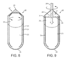
fig. 8 and 9 show different embodiments of a container according to the present invention, -
fig. 10 and 11 show different embodiments of a connection mechanism for connecting the container to the device for preparing a frozen confection according to the present invention, -
fig. 12a and 12b show a further embodiment of a connection mechanism according to the present invention, -
fig. 13a to 13c show different embodiments of a scraper and dispensing assembly within the container according to the present invention, -
fig. 14a shows a first embodiment of a container holder heat exchanger according to the present invention, -
fig. 14b shows a second embodiment of a container holder heat exchanger according to the present invention, -
fig. 15 and16 show a second embodiment of a container holder according to the present invention, -
fig. 17 shows an image series of a container when preparing a frozen confection according to the present invention and -
fig. 18 is a flow chart showing schematically the process steps for preparing a frozen confection according to the present invention. - The present invention proposes a container which is designed for being inserted into a device for preparing a frozen confection. The container comprises ingredients and processing assembly for producing a frozen confection. The ingredients enable the preparation of frozen confection in situ. For this purpose the container comprises movable scrapers within the container which are designed to move, i. e. mix, scrape and aerate the ingredients within the container. The container further has a casing having physical properties allowing optimum heat transfer properties such that heat energy is transferred from the ingredients to an external source.
- The present invention further relates to a container holder adapted to receive the container and having properties to allow an optimum heat transfer and heat (energy) removal from the ingredients in the container to the ambient (external source).
- The present invention further relates to a device for preparing a frozen confection having therein a container holder into which the container is inserted. The device is adapted to cool the container and to move the processing unit within the container. For this purpose any type of movement unit can be connected by appropriate means to the processing unit of the container to transfer kinetic energy to the processing unit within the container.
- The present invention thus provides a device, which comprises means to receive the container, to cool the container and to apply a moving force to the processing unit within the container, so that by cooling and processing the ingredients within the container a frozen confection can be prepared.
-
Fig. 1 shows a schematic block diagram of adevice 1 for preparing a frozen confection according to the present invention. - The
device 1 comprises acontainer holder 6 which is designed to receive the container. The container holder hereby allows the easy insertion and removal of the container comprising the ingredients for preparing a frozen confection. - Connected to the
container holder 6, which functions as a heat exchanger, is acooling system 9 which comprises a refrigeration and circulatory heat transfer system to cool the container within thecontainer holder 6 as rapidly as possible. Thecontainer holder 6 has optimum heat transfer properties, as will be explained in detail later, for allowing optimum cooling of the ingredients within the container. - Optionally, the
device 1 can comprise a defrostingsystem 10 to minimize the frosting of any heat exchanging parts. The defrostingsystem 10 can for example be a hot gas defrost system that can comprise a switchable reversed compressor gas flow valve, a defrosting plate and/or a dry air circulation system with the humidified air. - The
device 1 further optionally can comprise an aeration system 8. The aeration and possibly air cooling system which is connected to thecontainer holder 6 may comprise a mini compressor which, by proprietary design, allows the aeration of the ingredients and also facilitates the freezing of the ingredients within the container. One possibility is to flow the gaseous phase into a hollow processing unit within the container so that via several exit holes within the processing unit the gaseous phase can be delivered into the ingredients. A further possibility is to insert pressurized gaseous phase at an inlet system within the container. - In one embodiment the aeration system 8 can comprise a pressurized air injection system which pressurizes the head space within the container above the readily prepared frozen confection to dispense the frozen confection from the container.
- The
device 1 further comprises amovement unit 3 providing a movement system which can be attached to a corresponding connector of the container, so that kinetic energy is transferred to the processing unit within the container. In one embodiment, themovement unit 3 comprises a movable, e.g. rotatable and/or oscillating, plunger which can be connected to a corresponding connector of the container. - Optionally, the
device 1 can also comprise anopening unit 4 which is adapted to open the container after the preparation of the frozen confection, so that the frozen confection can be dispensed from the container. Alternatively, theopening unit 4 can also be omitted and a manual opening step by a customer can be provided. - The
device 1 further comprises adispensing unit 5 which is adapted to dispense the prepared frozen confection from the container after the container has been opened either manually by a customer or by theopening unit 4. The dispensingunit 5 thus forces the freshly made frozen confection out of the container. Alternatively, the dispensing unit can activate the opening of the container using appropriate force by removing the closure system in place. - In a preferred embodiment the
device 1 comprises amotor 2. Themotor 2 is adapted to drive thedispensing unit 5, theopening unit 4 and themovement unit 3 and to provide the necessary movement to themovement unit 3. In an alternative embodiment, themotor 2 can also be omitted and can be provided by other means, e. g. a crank handle, which allows the user to manually drive the different components, specifically theconnection mechanism 3. - In case that a
motor 2 is provided, themotor 2 can also be used to drive theopening unit 4 and/or thedispensing unit 5. But it is also possible that one or both units are only activated manually or by other means. Other means could include the use of additional motors as required to perform separate operations individually for processing and dispensing. - Additionally, the
device 1 can comprise anactivation unit 11 which is adapted to activate the whole processing. Theactivation unit 11 starts the cooling by thecooling system 9 and in case that amotor 2 is provided, theactivation unit 11 starts themotor 2. If themotor 2 is omitted or if themotor 2 only drives apart of the units, then theactivation unit 11 can be directly connected with the respective units and activate the respective units directly. If an aeration system 8 and adefrosting system 10 are present, then also these systems can be activated by theactivation unit 11. - Also shown in
fig. 1 is areceptacle 7 which is adapted to receive the frozen confection when dispensed from the container. Thereceptacle 7 is of course removable from thedevice 1. -
Fig. 2 and3 show a preferred embodiment of a device for preparing a frozen confection according to the present invention. It is to be noted thatfig. 2 and3 are only examples and that the present invention comprises also every other structure and shape of a device for preparing a frozen confection falling under the scope of the present claims. -
Fig. 2 and3 show a perspective side/front view of adevice 1 according to the present invention.Fig. 2 hereby shows the device in a closed state andfig. 3 shows the device in an open state, where it is possible to insert a container into the device. - The
device 1 comprises acasing 12 which houses several components of thedevice 1. Provided within thecasing 12 are preferably a condenser and a compressor (in the case of conventional vapour compression refrigeration, which form the cooling system 9). Alternatively, any other embodiment of acooling system 9 can be provided within the casing. - Likewise, the casing 12 houses also all other components previously described with reference to
fig. 1 . At the bottom part of the casing 12 asupport 17 can be provided which is adapted to receive thereceptacle 7 thereon, into which the readily prepared frozen confection can be dispensed through theoutlet 13. In one embodiment thesupport 17 can also be cooled by thecooling system 9. - In the following, different possibilities of revealing the
container holder 15 will be explained. - In a preferred embodiment the
device 1 comprises amovable portion 14, which can be moved into a predefined direction, so that thecontainer holder 15 is revealed, so that thecontainer 20 can be inserted into thecontainer holder 15. - In this preferred embodiment the
device 1 comprises amovable portion 14. Hereby themovable portion 14 itself can comprise thecontainer holder 15. Consequently, by moving themovable portion 14, thecontainer holder 15 is dragged into a position enabling the insertion of thecontainer 20. Alternatively, themovable portion 14 can be a portion which covers thecontainer holder 15 and by moving themovable portion 14 into a predefined direction, thecontainer holder 15 is exposed. - In the embodiment shown in
fig. 2 and3 , themovable portion 14 is implemented as adrawer 16 comprising thecontainer holder 15, which can be pulled out of thedevice 1 and pushed back into thedevice 1. By pulling thedrawer 16 out, thecontainer holder 15 is revealed and thecontainer 20 can be inserted into thecontainer holder 15. Afterwards thedrawer 16 can be pushed back into thedevice 1. -
Fig. 4 to 7 show different embodiments of an opening mechanism for opening thedevice 1 in such a way that thecontainer holder 15 is revealed and thecontainer 20 can be inserted. - All the embodiments comprise a
movable portion 14 which can be moved in such a way that thecontainer holder 15 is reachable so that thecontainer 20 can be inserted. - In
fig. 4 themovable portion 14 is again implemented asdrawer 16 comprising thecontainer holder 15, which slides alongbars 22 and in this way can be pulled out from the device and pushed back into thedevice 1. Thedrawer 16 hereby accomplishes a forward and backward movement as indicated by arrow A. -
Fig. 5 shows a further embodiment where the movingportion 14 is a portion above thecontainer holder 15 and can be rotated so that thecontainer holder 15 is revealed. The rotation hereby infig. 5 is indicated by arrow B. -
Fig. 6 shows a further embodiment of a movable portion, where the movable portion is a portion comprising thecontainer holder 15 and implemented as a fold-awayunit 19, which can be folded along a hinge downward as indicated by arrow C in order to reveal thecontainer holder 15. -
Fig. 7 shows a further embodiment, where themovable portion 14 is the portion above thecontainer holder 15 which can be moved along correspondingbars 22 in order to reveal thecontainer holder 15 and to close thedevice 1 again. - In a further alternative embodiment also two or more movable portions can be provided.
- In the following with reference to
Fig. 8 and 9 , different embodiments of thecontainer 20 will be explained in more detail. Generally, the container comprisesingredients 23 providing a frozen confection after being processed: cooled, scraped, mixed, kneaded and/or aerated. The container further comprises a processing unit within thecontainer 20 to mix, agitate, and aerate the ingredients 23.In one embodiment as shown inFig. 8 and 9 the processing unit is implemented asscraper 24, which processes theingredients 23 and scrapes theingredients 23 from the internal wall surfaces of thecontainer 20. Thescraper 24 comprises one or more blades, which preferably precisely contact the inside wall of thecontainer 20. - The
container 20 further comprises anopening 38 through which the readily prepared frozen confection can be dispensed. Theopening 38 can comprise a breakable end or removable seal. Alternatively, a one-way dispensing orifice can be provided which is controlled by a pressure valve mechanism for dispensing. - The
scrapers 24 or dashers scrape the inside surface of the container during freezing and in addition the scrapers facilitate the mixing and aeration process during freezing. - The container is preferably, but not limited to, made from a material with optimum heat transfer properties, e. g. aluminium, steel or the like.
- Preferably, all materials of the
container 20 and also all packaging materials of thecontainer 20 are made from disposable and recyclable materials. - The physical properties of the
casing 25 of thecontainer 20 allow energy to be transferred from theingredients 23 to an external source, i. e. heat energy to be transferred from theingredients 23 to thecooling system 9. - The
ingredients 23 preferably comprise a chilled or shelf-stable confection and a gaseous phase, e. g. air. In a preferred embodiment the amount ofingredients 23 range from 25 % to 80 % by volume and the rest of thecontainer 20 is filled withgaseous phase 26. Theingredients 23 hereby provide a single portion of frozen confection. - Specifically, the single portion of chilled or shelf-stable ingredients mix is capable of producing between 50 to 300 ml of frozen confection. Instead of air also any other type of gas can be provided within the
container 20 to allow for aeration and overrun. Alternatively or additionally, nitrogen can be provided within thecontainer 20 for aseptic filling and extended shelf life. - When used in the present invention the term "frozen confection" is intended to refer to different types of frozen confection. Non-limiting examples are ice cream, sorbet, sherbet, water ice, frozen yogurt, frozen dairy, soft ice, Mellorine, frozen custard, non-dairy frozen confection, milk ice, ice lolly, gelato or frozen jelly.
- In
fig. 8 and 9 possible but not limiting embodiments of acontainer 20 are shown. - The
container 20 comprises atranslation unit 27 which is adapted to transfer kinetic energy of themovement unit 3 of thedevice 1, comprising for example a plunger or the like, to thescrapers 24. Thetranslation unit 27 therefore is attached to thescrapers 24 and comprises aconnector 28 for connecting to themovement unit 3. - The
connector 28 preferably provides a quick connection to the device and motor assembly, i.e. a connection which can be fast and easily achieved. - In the embodiment shown in
fig. 8 thetranslation unit 27 is integrated into the top of thecontainer 20. Thescrapers 24 are attached to thetranslation unit 27. Thetranslation unit 27 comprises aconnector 28 which can be connected to themovement unit 3, e.g. a respective plunger or the like of thedevice 1 in order to transfer a movement of themovement unit 3 via thetranslation unit 27 to thescrapers 24. The translation unit can for example be attached to the container in such a way to allow a rotational, axially linear and/or oscillating movement. -
Fig. 9 shows a further embodiment of acontainer 20. In this case thetranslation unit 27 comprises avertical pole 29, which is attached to the top of thecontainer 20, and at the top comprises theconnector 28. Thevertical pole 29 at its lower end has connected thereto adisc 30 having attached thereto thescrapers 24. Specifically, in the preferred embodiment thedisc 30 comprisesgrooves 31, into which thescrapers 24 are inserted, whereby the grooves allow to transfer the rotational movement from thetranslation unit 27 to thescrapers 24 but at the same time allow thescrapers 24 to slide along thegrooves 31. - As indicated by corresponding arrows when the
connector 28 is connected to a plunger or the like being for example driven by e. g. a motor spindle assembly, the movement can be transferred to thescrapers 24 within thecontainer 20. - In the following different possibilities how to connect the
connector 28 to themovement unit 3 of thedevice 1 will be explained. - In the following embodiments, the
device 1 comprises aplunger 33, which is connected to theconnector 28. But also every other possible shape and/or mechanism can be used to transfer the movement from themovement unit 3 to thescrapers 24. -
Fig. 10 shows a first embodiment where thecontainer 20 comprises aconnector 28 which is anembossment 32 on top of thecontainer 20. Theplunger 33 has a corresponding connection means 34 which has arecess 35 within (not shown in the figure) which fits exactly on theembossment 32. In a preferred embodiment theembossment 32 and therecess 35 have a rectangular shape, so that if theembossment 32 is inserted into therecess 35, the rotational force can be transmitted to the scrapers. More generally, the embossment and the recess have to cant with each other to allow for a rotational movement. -
Fig. 11 shows a further embodiment, where thecontainer 20 comprises arecess 37 and theplunger 33 at its end has connected thereto apivot 36, which fits into therecess 37. In this preferred embodiment thepivot 36 and therecess 37 are also rectangular or may have any other shape allowing to cant with each other and to transfer a rotational movement. -
Fig. 12a and 12b show a further embodiment of a connection mechanism according to the present invention. In this case theconnector 28 has abasement member 40 and at least oneupper portion 42 above thebase member 40, so that between thebasement member 40 and the upper portion 42 agap 41 is formed, which is open on one side. - The
plunger 33 comprises at least one protrudingportion 39. For connecting theplunger 33 to theconnector 28, theplunger 33 is lowered down onto thebasement member 40, so that the protrudingportion 39 lies on thebasement member 40. In the next step as shown infig. 12b theplunger 33 is rotated, so that the protrudingportion 39 is inserted into thegap 41 between thebasement member 40 and theupper portion 42. - With this fixation a rotational movement can be transferred, since the
gap 41 is closed on one side so that a rotational movement into the direction of the closed side of thegap 41 as indicated by arrow E is possible. At the same time, since the protrudingportion 39 is fixed within thegap 41, also a vertical movement, e. g. an oscillating movement can be translated to the scrapers 24 (not shown infig. 12a and 12b ). - A rotational movement of the
scrapers 24 and in addition also a vertical, i. e. an oscillating movement of the scrapers is described according to a further embodiment of the present invention. In this preferred embodiment during the rotational scraping process the scraper is simultaneously oscillated in the direction parallel to the axially linear direction of thescrapers 24 or generally of the processing unit and thecontainer 20. - The scraper oscillation during rotational scraping is actuated by the spindle which is coupled to a drive system and actuating mechanism such as piezoelectric, magnetical, electrodynamic, mechanical or a reciprocating electric motor.
- The amplitude and frequency of the oscillatory motion are selected to maximize the scraping efficiency of the scraper. The preferable amplitude and frequency ranges are 0,01 mm to 25 mm and 50 Hz to 50 kHz respectively.
- The oscillatory movement in addition to the rotational movement has several advantages. The oscillation imparted to the blade of the
scraper 24 reduces the interfacial coefficient of friction between the blade edge and the scraped surface (on which the frozen confection ingredient particles are formed). This oscillation is beneficial because such high frequency blade vibrations can improve the cutting performance of the blade minimising the unwanted influence of material and fabrication defects in the blade precision and sharpness. This increases the efficiency of scraping in terms of process time, particle size distribution, frozen confection quality and energy input. - The
scrapers 24 can be designed in a number of different formats. They can be single or multi bladed, and have different contact angles. Any design which helps maximize the scraping efficiency is possible. In the embodiments shown in the present invention, thescrapers 24 comprise two blades, but the present invention is not limited to the shown embodiments. - Additionally, the scrapers or at least a part of the
scrapers 24 can be hollow, so that a gaseous phase can be forced through the scrapers. Thescrapers 24 in this embodiment further have therein small holes, so that through the tiny holes gaseous phase is injected into the frozen confection to maximize the aeration overrun and freezing efficiency. - In
fig. 13a and 13b a processing unit according to a first embodiment of the present invention will be described in more detail. In this embodiment the processing unit is ascraper assembly 43. In the figures thecontainer 20 is omitted for the sake of clarity. The scraper assembly comprises aroundish bottom plate 44, which may have any other shape dependent on the shape of thecontainer 20. Fixedly attached to the bottom plate arescrapers 24. Thescrapers 24 as previously described are inserted intorespective grooves 31 of adisc 30 which by a correspondingconnector 28 is connected to theplunger 33. Thegrooves 31 enable an intimate coupling between thedisc 30 and thescrapers 24 to allow a rotational as well as a vertical, i. e. axially linear, oscillatory or vibrational movement to be transmitted to thescrapers 24. In an alternative embodiment, thebottom plate 44 can also be omitted. -
Fig. 13a shows the state where the scrapingassembly 43 is used to scrape theingredients 23 within thecontainer 20. After the frozen confection is prepared, then a dispensing mechanism can be activated as shown infig. 13b . For this purpose theplunger 33 is pushed into a direction parallel to thescrapers 24, in direction of the bottom of thecontainer 20, where theopening 38 is provided, and as indicated by arrow F in the figures. Since thescrapers 24 can slide along thegrooves 31 within thedisc 30, i.e. theprecision grooves 31 allow a scraper passage, thescrapers 24 mainly remain in the same position within the container and thedisc 30 slides along thescrapers 24 so as to push the prepared frozen confection out of the container. -
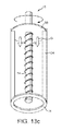
Fig. 13c shows a second embodiment of a processing unit with ascraper assembly 43, in which acentral screw thread 54 runs along the central axis of the container and is used to guide thedisc 30 from the top of thecontainer 20 to the bottom, where theopening 38 is provided, and as indicated by arrow G in the figure. For this purpose aconnector 28 is attached to the disc 30 (and therefore attached thereto the scrapers 24). Thedisc 30 has a central thread which sits on the unthreaded part of thecentral screw thread 54 on top of thecontainer 20 but is not engaged to it. With this connection a rotational movement can be transferred to thedisc 30 and therefore to thescraper assembly 43. After the frozen confection is prepared, then a dispensing mechanism can be activated by pushing thedisc 30 further down and engaging thecentral screw thread 54. Once this is done, a unidirectional rotation byconnector 28 will force thedisc 30 also to rotate and move along and down thecentral screw thread 54 towards the opening 38 so as to push the prepared frozen confection out of the container. - Alternative dispensing mechanisms are to provide an inflatable bag on top of the container, which by the aeration system 8 can be inflated. Alternatively, pressurized air can be inserted into the container to force the prepared frozen confection out of the
container 20. - In the following, the
container holder 15 within thedevice 1 will be explained. Generally, thecontainer holder 15 has a shape being adapted to the shape of thecontainer 20, i.e. a shape which prior to processing allows thecontainer 20 to rest tightly on thecontainer holder 15. - In a preferred embodiment, the
container 20 has a cylindrical shape and consequently also thecontainer holder 15 has a cylindrical shape which allows to tightly wrap thecontainer 20. -
Fig. 14a shows a first embodiment of acontainer holder 15 according to the present invention. In this first embodiment thecontainer holder 15 is made of one piece. - The
container holder 15 is a heat exchanger that comprises awall 46 surrounding thecontainer holder 15 and along thiswall channels 45 are running vertically along the length of thecontainer holder 15. The design of thechannels 45 allows for maximum heat transfer rates. The heat exchange surface is the internal surface of thecontainer holder 15. The cooling, e. g. fluid, or evaporating refrigerant gas flows along thesechannels 45 at very low temperatures. The surface of thechannels 45 comprises, but not limited to a rough surface in order to make refrigerant flow turbulent and thus enhance heat transfer. Heat is taken up due to the refrigerant's change of state caused by the low pressure in the heat exchanger, and consequently the low temperature. The low temperature of the heat exchanger is driving the exchange of heat fromingredients 23 to the refrigerant. Liquid refrigerant is preferably, but not limited to, injected at the bottom of the heat exchanger, whereas the refrigerant in the state of vapour is removed from the top of the heat exchanger. - In case defrosting of the internal heat exchange surface is necessary and the
cooling system 9 is conventional vapour compression/evaporation, an automatic defrosting mechanism is provided by means of a reversible and controllable hot gas defrost valve which allows just sufficient quantities of hot gas from thecooling system 9 to be forced into the hollow channels of the container holder such that the temperature of the heat exchange surface is raised to a predetermined temperature and the surface is defrosted. - In case defrosting of the internal heat exchange surface is necessary and the
cooling system 9 is thermoelectric (peltier) powered, an automatic electronic switch will reverse the polarity of the electric circuit powering the thermoelectric devices such that cool and hot -sides of the devices are reversed and the cool-side of the thermoelectric devices becomes the hot-side and the hot-side becomes cold-side such that the temperature of the heat exchange surface is raised to a predetermined temperature and the surface is defrosted. - In case a frosting plate is provided, the
frosting plate 53 is placed at the bottom section of thecontainer holder 15 to prevent frosting of the main heat exchanger surfaces. -
Fig. 14b shows a second embodiment of a container holder heat exchanger according to the present invention with an alternative cooling system based on a thermoelectric peltier system. Thecontainer holder 15 therefore comprises a one or morethermoelectric peltier units 55 attached to the external side wall of thecontainer holder 15. Corresponding power leads 56 are connected to thethermoelectric unit 55. The number, shape and size of thermoelectric units that can be utilised are not limited to the embodiment shown in the figure. - A cooling fluid entry and
exit 58 is also provided for a fluid basedheat removal cell 57 for the heat energy produced by the thermoelectric units. The cooling fluid entry andexit 58 is connected to the fluid basedheat removal cell 57. Alternatively, the heat energy produced by the thermoelectric units can be cooled directly by the surrounding environment, by an air fan, or other heat removal mechanism. -
Fig. 15 shows a preferred embodiment of acontainer holder 15 according to the present invention. This embodiment is also shown in a perspective view infig. 16 . In this embodiment thecontainer holder 15 comprises two portions, e.g. two hemisphere parts, which are connected via a correspondinghinge 47 and can be moved in relation to each other so as to open and close thecontainer holder 15. This facilitates the insertion of acontainer 20. In order to enable a tight fit and to allow for optimum heat transfer rates an opening and closing mechanism is required. In this embodiment, apin 49 withinholes 48 of the two parts of thecontainer holder 15 is provided which allows to reduce thegap 50 between the two parts of thecontainer holder 15 and to squeeze thecontainer 20 within thecontainer holder 15. - With this preferred embodiment including the hinged design of the
container holder 15, an easy insertion and removal of thecontainer 20 is possible and at the same time a tight fit for maximum heat transfer between the surfaces of thecontainer 20 and thecontainer holder 15 is ensured. - The
container holder 15 according to the second embodiment has several advantages. Due to the design of thecontainer holder 15 and the heat transfer unit (evaporator) a minimum mass and a maximum primary surface for heat transfer are provided. The preferably rough surface, where the refrigerant is in contact with the internal finned channels of thecapsule holder 15, ensures a maximum heat transfer due to turbulent flow. The design further allows a low pressure drop and a generous volume for the refrigerant. -
Fig. 17 shows an image series of an example how the different steps for preparing a frozen confection could be accomplished. - In image a) a
container 20 is shown which preferably comprises a removable and/or aseptic, preferably tamper evident seal (peel-off) 51 which as shown in image b) can be removed to reveal theconnector 28. Theseal 51 preferably is a hygienic tear-off seal revealing theconnector 28. As already explained, theconnector 28 has a corresponding design to deliver the rotational movement, and in a preferred embodiment the rotational together with the oscillatory movement, to thescrapers 24. As shown in image c) theplunger 33 is then connected to theconnector 28 so that as shown in image d) the rotational force can be transmitted to thescrapers 24. As schematically shown theingredients 23 when being cooled and rotated then result in the finalfrozen confection 52 and is ready. In the last step as shown in image e) the dispensing mechanism is activated by pushing thedisc 30 into a direction towards the opening 38 of thecontainer 20 so as to dispense the preparedfrozen confection 52. -
Fig. 18 shows a flow chart with an overview over the different steps for preparing afrozen confection 52 according to the present invention. - The process starts in step S0.
- In step S1 the
container 20 is received by thedevice 1, i. e. is input into thecontainer holder 15. After removing theseal 51 from theconnector 28, in the next step S2 themovement unit 3 of the device is connected to theconnector 28 of thecontainer 20. This can be accomplished either manually by a user or automatically by thedevice 1. - In the following step S3 the
cooling system 9 is activated and begins to cool thecontainer 20 rapidly and at the same time in step S4 themovement unit 3 is activated. In the next step S5 thefrozen confection 52 is produced by cooling and processing theingredients 15. - Once the optimal temperature and consistency of the
frozen confection 52 is reached, then in the next step S6 themovement unit 3 is stopped and in step S7 theopening unit 4, if present, can be activated in order to open thecontainer 20. As previously described this step can also be omitted and accomplished manually by a customer. - In the next step S8 the dispensing
unit 5 is then activated and in the following step S9 thefrozen confection 52 is dispensed from thecontainer 20. Preferably, theplunger 33 which previously delivered the movement to thescrapers 24 now acts as dispenser forcing thefrozen confection 52 through theopening 38. - In step S10 the
empty container 20 is then removed from thedevice 1. Optionally, then a defrosting step S11 can be accomplished by activating the defrosting system, if present. This has the advantage that it is assured that there is no frosting on the container holder surface in readiness to receive the next container. The defrosting step can also be provided between or during other steps and/or between or during a plurality of steps. But in the preferred embodiment defrosting is accomplished after each production cycle. The process ends in step S12 and thedevice 1 is thus ready for receiving anew container 20 and preparing a further single portion of freshly made frozen confection. - The present invention thus enables the preparation of a frozen confection, which can be freshly prepared in single portions by a closed system. The containers provide a pre-dosed packaging containing all the necessary ingredients for preparing the frozen confection. The frozen confection is prepared inside the container.
- With the present invention it is further possible to prepare several different types of frozen confections in a short time. Since the container is dispensable and does not need to be cleaned and importantly since key parts of the device do not come into contact with the frozen confection, the handling is simplified and the need for cleaning is reduced and/or eliminated.
-
- (1)
- device for preparing a frozen confection
- (2)
- motor
- (3)
- movement unit
- (4)
- opening unit
- (5)
- dispensing unit
- (6)
- container holder
- (7)
- receptacle
- (8)
- aeration system
- (9)
- cooling system
- (10)
- defrosting system
- (11)
- activation unit
- (12)
- casing
- (13)
- outlet
- (14)
- movable portion
- (15)
- container holder
- (16)
- drawer
- (17)
- support
- (19)
- fold-away unit
- (20)
- container
- (22)
- bar
- (23)
- ingredients
- (24)
- scraper
- (25)
- casing of container
- (26)
- gas
- (27)
- translation unit
- (28)
- connector
- (29)
- pole
- (30)
- disc
- (31)
- grooves
- (32)
- embossment
- (33)
- plunger
- (34)
- connection means
- (35)
- recess
- (36)
- pivot
- (37)
- recess
- (38)
- opening
- (39)
- protruding portion
- (40)
- basement member
- (41)
- gap
- (42)
- upper portion
- (43)
- scraper assembly
- (44)
- bottom plate
- (45)
- channel
- (46)
- wall
- (47)
- hinge
- (48)
- hole
- (49)
- pin
- (50)
- gap
- (51)
- seal
- (52)
- frozen confection
- (53)
- frosting plate
- (54)
- central screw thread
- (55)
- thermoelectric unit
- (56)
- power leads
- (57)
- fluid based heat removal cell
- (58)
- cooling fluid entry and exit
Claims (15)
- Container (20) designed for being inserted into a device (1) for preparing a frozen confection (52),
said container (20) comprising at least one scraper (24) movable within the container (20) and
said container (20) containing ingredients (23) for producing a frozen confection (52) when being cooled and moved. - Container (20) according to claim 1,
wherein said container (20) has a casing (25) having physical properties allowing heat energy to be transferred from the ingredients (23) to the ambient (external source). - Container according to claim 2,
wherein said casing (25) is made of a material with good heat transfer properties, preferably steel or aluminium. - Container according to any of the preceding claims, further comprising a connector (28) enabling connection to an external movement unit (3) for transferring a movement from the external movement unit (3) to the at least one scraper (24),
wherein the connector (28) preferably enables connection to the external movement unit (3) in such a way, that a rotational movement, preferably a rotational movement together with an oscillating movement, can be transferred to the at least one scraper (24). - Container according to any of the preceding claims, further comprising an outlet opening (38) for dispensing the frozen confection (52), wherein the outlet opening (38) has a removable and/or breakable seal.
- Container (20) according to any of the preceding claims,
wherein the ingredients (23) provide a single portion of frozen confection (52) comprising 50ml to 300ml. - Container (20) according to any of the preceding claims,
wherein the ingredients (23) comprise an ambient shelf-stable or chilled confection and a gas. - Container (20) according to any of the preceding claims, wherein the frozen confection (52) is one of ice cream, sorbet, sherbet, water ice, frozen yoghurt, frozen dairy, soft ice, Mellorine, frozen custard, non-dairy frozen confection, milk ice, ice lolly, gelato or frozen jelly.
- Container holder (15) adapted to receive a container (20) comprising ingredients (23) for preparing a frozen confection,
said container holder (15) having a heat exchange surface being in tight contact with the container (20) and
allowing heat energy to be transferred from the ingredients (23) to an external source. - Container holder (15) according to claim 9, further comprising channels (45) allowing a cooling agent to run along the heat exchange surface.
- Container holder according to claim 9 or 10, comprising two portions connected to each other by a hinge (47) and
a pin (49) for fixing the two portions to each other when a container (20) is inserted. - A device (1) for preparing a frozen confection, comprising
a container holder (15) for receiving a container (20) having therein ingredients (23) for preparing a frozen confection (52) when being cooled and moved,
a cooling system for cooling the ingredients (23), and
a movement unit (3) connectable to the container (20) for transferring a movement to at least one scraper (24) movable within the container (20). - Device (1) according to claim 12,
wherein the movement unit (3) is adapted to transfer a rotational movement, preferably a rotational and an oscillatory movement, to the at least one scraper (24). - A system comprising a device (1) for preparing a frozen confection according to any of claims 12 or 13, said device (1) comprising a container holder (15) according to any of claims 9 to 11, and
said system further comprising a container (20) according to any of claims 1 to 8 inserted into the container holder (15). - A method for preparing a frozen confection, comprising the steps of
providing a container (20) having therein ingredients (23) for preparing a frozen confection (52) when being cooled and moved,
cooling the container (20) and
transferring a movement to at least one scraper (24) movable within the container (20).
Priority Applications (6)
| Application Number | Priority Date | Filing Date | Title |
|---|---|---|---|
| EP09163869A EP2266418A1 (en) | 2009-06-26 | 2009-06-26 | Container having ingredients for preparing a frozen confection, container holder and device for preparing a frozen confection |
| US13/379,182 US20120096876A1 (en) | 2009-06-26 | 2010-06-11 | Container having ingredients for preparing a frozen confection, container holder and device for preparing a frozen confection |
| CA2765170A CA2765170A1 (en) | 2009-06-26 | 2010-06-11 | Container having ingredients for preparing a frozen confection, container holder and device for preparing a frozen confection |
| AU2010264891A AU2010264891A1 (en) | 2009-06-26 | 2010-06-11 | Container having ingredients for preparing a frozen confection, container holder and device for preparing a frozen confection |
| PCT/EP2010/058214 WO2010149509A1 (en) | 2009-06-26 | 2010-06-11 | Container having ingredients for preparing a frozen confection, container holder and device for preparing a frozen confection |
| EP10725139A EP2445354A1 (en) | 2009-06-26 | 2010-06-11 | Container having ingredients for preparing a frozen confection, container holder and device for preparing a frozen confection |
Applications Claiming Priority (1)
| Application Number | Priority Date | Filing Date | Title |
|---|---|---|---|
| EP09163869A EP2266418A1 (en) | 2009-06-26 | 2009-06-26 | Container having ingredients for preparing a frozen confection, container holder and device for preparing a frozen confection |
Publications (1)
| Publication Number | Publication Date |
|---|---|
| EP2266418A1 true EP2266418A1 (en) | 2010-12-29 |
Family
ID=41510466
Family Applications (2)
| Application Number | Title | Priority Date | Filing Date |
|---|---|---|---|
| EP09163869A Withdrawn EP2266418A1 (en) | 2009-06-26 | 2009-06-26 | Container having ingredients for preparing a frozen confection, container holder and device for preparing a frozen confection |
| EP10725139A Withdrawn EP2445354A1 (en) | 2009-06-26 | 2010-06-11 | Container having ingredients for preparing a frozen confection, container holder and device for preparing a frozen confection |
Family Applications After (1)
| Application Number | Title | Priority Date | Filing Date |
|---|---|---|---|
| EP10725139A Withdrawn EP2445354A1 (en) | 2009-06-26 | 2010-06-11 | Container having ingredients for preparing a frozen confection, container holder and device for preparing a frozen confection |
Country Status (5)
| Country | Link |
|---|---|
| US (1) | US20120096876A1 (en) |
| EP (2) | EP2266418A1 (en) |
| AU (1) | AU2010264891A1 (en) |
| CA (1) | CA2765170A1 (en) |
| WO (1) | WO2010149509A1 (en) |
Cited By (22)
| Publication number | Priority date | Publication date | Assignee | Title |
|---|---|---|---|---|
| ITVE20110023A1 (en) * | 2011-04-19 | 2012-10-20 | Gherardo Viani | SINGLE-DOSE ICE CREAM |
| WO2014067987A1 (en) * | 2012-10-30 | 2014-05-08 | Nestec S.A. | Machine, container, system and method for preparing ice cream or chilled desserts on demand |
| WO2015063094A1 (en) | 2013-10-30 | 2015-05-07 | Nestec S.A. | Machine and system for preparing a cooled food product with aerated or whipped texture in controlled manner |
| WO2015063092A1 (en) * | 2013-10-30 | 2015-05-07 | Nestec S.A. | Machine, system and method for preparing a cooled confectionery product with aerated texture |
| WO2015063091A1 (en) * | 2013-10-30 | 2015-05-07 | Nestec S.A. | Machine for preparing cooled aerated confectionary with accurate temperature control |
| WO2015124848A1 (en) * | 2014-02-21 | 2015-08-27 | Ereie - Energy Research Innovation Engineering | Machine for cooling with dry ice |
| WO2015169841A1 (en) * | 2014-05-07 | 2015-11-12 | Nestec S.A. | System for preparing chilled or frozen products |
| WO2017218952A1 (en) | 2016-06-16 | 2017-12-21 | Sigma Phase, Corp. | System for providing a single serving of a frozen confection |
| WO2019140251A1 (en) * | 2018-01-12 | 2019-07-18 | Sigma Phase, Corp. | System for providing a single serving of a frozen confection |
| WO2019175578A1 (en) * | 2018-03-13 | 2019-09-19 | Ispresso Limited | Scraper locking arrangement |
| WO2019175575A1 (en) * | 2018-03-13 | 2019-09-19 | Ispresso Limited | Scraper blade |
| IT201800005330A1 (en) * | 2018-05-14 | 2019-11-14 | MACHINE FOR THE MAKING OF LIQUID OR SEMI-LIQUID FOOD PRODUCTS. | |
| WO2020037287A1 (en) * | 2018-08-17 | 2020-02-20 | Sigma Phase, Corp. | Rapidly cooling food and drinks |
| WO2020037293A1 (en) * | 2018-08-17 | 2020-02-20 | Sigma Phase, Corp | Rapidly cooling food and drinks |
| WO2020037296A1 (en) * | 2018-08-17 | 2020-02-20 | Sigma Phase, Corp. | Providing single servings of cooled foods and drinks |
| US10667542B2 (en) | 2016-06-16 | 2020-06-02 | Sigma Phase, Corp. | System for providing a single serving of a frozen confection |
| US11109610B2 (en) | 2020-01-15 | 2021-09-07 | Coldsnap, Corp. | Rapidly cooling food and drinks |
| US11279609B2 (en) | 2020-06-01 | 2022-03-22 | Coldsnap, Corp. | Refrigeration systems for rapidly cooling food and drinks |
| US11781808B2 (en) | 2019-04-09 | 2023-10-10 | Coldsnap, Corp. | Brewing and cooling a beverage |
| US11827402B2 (en) | 2021-02-02 | 2023-11-28 | Coldsnap, Corp. | Filling aluminum cans aseptically |
| TWI825217B (en) * | 2018-11-09 | 2023-12-11 | 美商寇德斯納普公司 | Aluminum can for providing frozen confection, pod for forming frozen confection, pod for providing cold food or drink, and can for providing cold beverage or frozen confection |
| IT202300008244A1 (en) * | 2023-04-27 | 2024-10-27 | Tooa S P A | COOLING SYSTEM AND ICE CREAM MAKING MACHINE INCLUDING SUCH SYSTEM. |
Families Citing this family (40)
| Publication number | Priority date | Publication date | Assignee | Title |
|---|---|---|---|---|
| CA3027306C (en) | 2012-02-14 | 2021-05-18 | Solo Gelato Ltd. | System and method for the preparation of cooled edible products |
| EP3032961B1 (en) | 2013-08-14 | 2019-04-17 | Solo Gelato Ltd. | System for the preparation of cooled edible products |
| DE102014115322A1 (en) * | 2014-10-21 | 2016-04-21 | Vorwerk & Co. Interholding Gmbh | Food processor with cooling device |
| US10674742B2 (en) * | 2015-01-06 | 2020-06-09 | Tangent Foods International Limited | System and method for making ice cream |
| JP2018515174A (en) | 2015-04-27 | 2018-06-14 | ネステク ソシエテ アノニム | Machine for preparing cooled or heated products with precise temperature control |
| WO2016177630A1 (en) | 2015-05-06 | 2016-11-10 | Nestec S.A. | Deployable stirring member |
| BR112018014216B1 (en) | 2016-02-05 | 2022-06-07 | Unilever Ip Holdings B.V. | Confectionery and frozen products |
| GB2547895B (en) * | 2016-02-25 | 2022-04-06 | Kenwood Ltd | Kitchen appliance, food processor and safety interlock arrangement |
| US10334868B2 (en) | 2016-06-16 | 2019-07-02 | Sigma Phase, Corp. | System for providing a single serving of a frozen confection |
| US20230373708A1 (en) * | 2016-06-16 | 2023-11-23 | Coldsnap, Corp. | Frozen protein shakes |
| DE102017213368A1 (en) * | 2017-08-02 | 2019-02-07 | BSH Hausgeräte GmbH | Capsule and beverage system for making a beverage |
| JP7072927B2 (en) * | 2017-12-17 | 2022-05-23 | アドヴァンター・イノヴェイションズ・ピーティイー・リミテッド | Capsule-based food mixing / discharging system and related methods |
| EP3536637B1 (en) | 2018-03-05 | 2020-09-16 | Nootrie AG | Capsule for preparing a beverage |
| GB201803972D0 (en) * | 2018-03-13 | 2018-04-25 | Ispresso | Confection chilling arrangement |
| CN108618060B (en) * | 2018-05-08 | 2022-01-14 | 福建亲亲股份有限公司 | Method for making multilayer jelly |
| CN108618059B (en) * | 2018-05-08 | 2022-01-14 | 福建亲亲股份有限公司 | Method for making jelly with filling |
| US20240219111A1 (en) * | 2018-08-17 | 2024-07-04 | Coldsnap, Corp. | Rapidly Cooling Food and Drinks |
| US20220205712A1 (en) * | 2018-08-17 | 2022-06-30 | Coldsnap, Corp. | Rapidly Cooling Food and Drinks |
| FR3087997A1 (en) * | 2018-11-05 | 2020-05-08 | Charles Cazenave De Lacaussade | INNOVATIVE DEVICE FOR MANUFACTURING SOFT ICE CREAM "ITALIAN ICE CREAM" |
| EP3902450A1 (en) * | 2018-12-26 | 2021-11-03 | Société des Produits Nestlé S.A. | Device for delivering frozen or chilled beverages |
| US12336550B2 (en) * | 2019-02-05 | 2025-06-24 | Cremmjoy Inc. | Frozen confection machine |
| GB2596561A (en) * | 2020-06-30 | 2022-01-05 | Iconi Ltd | Confection apparatus |
| CA3186658A1 (en) * | 2020-07-23 | 2022-01-27 | Frederik VAN ISACKER | A device for preparing a frozen food product from a liquid mixture |
| WO2022017610A1 (en) * | 2020-07-23 | 2022-01-27 | Kempische Brik Centrale | A cup for a device for preparing a frozen food product from a liquid mixture and the device |
| USD1039911S1 (en) | 2022-09-30 | 2024-08-27 | Sharkninja Operating Llc | Bowl of a micro puree machine |
| USD1020383S1 (en) | 2022-09-30 | 2024-04-02 | Sharkninja Operating Llc | Bowl of a micro puree machine |
| USD1019255S1 (en) | 2022-09-30 | 2024-03-26 | Sharkninja Operating Llc | Housing of a micro puree machine |
| WO2024065579A1 (en) | 2022-09-30 | 2024-04-04 | Sharkninja Operating Llc | Micro puree machine with angled bowl |
| EP4593996A1 (en) | 2022-09-30 | 2025-08-06 | SharkNinja Operating LLC | Micro puree machine with fixed motors |
| US20240108176A1 (en) | 2022-09-30 | 2024-04-04 | Sharkninja Operating Llc | Micro puree machine with bowl and blade detection |
| US11819814B1 (en) | 2022-12-28 | 2023-11-21 | Sharkninja Operating Llc | Locking assembly for a micro puree machine |
| US12048395B2 (en) | 2022-12-28 | 2024-07-30 | Sharkninja Operating Llc | Twist off container and coupling assembly for a micro puree machine |
| US20250072463A1 (en) * | 2023-08-30 | 2025-03-06 | Sharkninja Operating Llc | Plunger retention assembly for a micro-puree machine |
| USD1076580S1 (en) | 2024-01-18 | 2025-05-27 | Sharkninja Operating Llc | Drink maker dasher |
| US20250234886A1 (en) | 2024-01-18 | 2025-07-24 | Sharkninja Operating Llc | Removeable collection tray for a drink maker |
| US12279629B1 (en) | 2024-01-18 | 2025-04-22 | Sharkninja Operating Llc | Mixing vessel baffles for a drink maker |
| US12593855B2 (en) | 2024-01-18 | 2026-04-07 | Sharkninja Operating Llc | Drink maker with detachably connectable mixing vessel |
| US12520857B1 (en) | 2025-01-09 | 2026-01-13 | Sharkninja Operating Llc | Multi-stage dispenser assembly |
| US12514262B1 (en) | 2025-01-10 | 2026-01-06 | Sharkninja Operating Llc | Feature for preventing material buildup in a mixing vessel of a drink maker |
| US12414578B1 (en) | 2025-03-14 | 2025-09-16 | Sharkninja Operating Llc | Shared output connector assembly for two drink maker dispenser assemblies |
Citations (18)
| Publication number | Priority date | Publication date | Assignee | Title |
|---|---|---|---|---|
| EP0106814A2 (en) | 1982-10-14 | 1984-04-25 | BREVETTI GAGGIA S.p.A. | Household ice-cream machine |
| BE901125A (en) | 1983-11-30 | 1985-03-15 | Cavalli Alfredo | APPARATUS FOR PRODUCING ICE CREAMS AND LIKE COLD PRODUCTS, PROVIDED WITH A REMOVABLE FREEZING CONTAINER. |
| US4540288A (en) | 1983-08-01 | 1985-09-10 | Brevetti Gaggia S.P.A. | Apparatus for producing ice cream utilizing the Peltier effect |
| EP0179027A2 (en) | 1984-10-15 | 1986-04-23 | BREVETTI GAGGIA S.p.A. | Ice-cream maker, particularly for domestic use |
| WO1986006936A1 (en) | 1985-05-28 | 1986-12-04 | Brevetti Gaggia S.P.A. | Improvements in ice-cream machines, particularly for domestic use |
| WO1988007330A1 (en) | 1987-04-03 | 1988-10-06 | Lester Brown | Modular self-dispensing frozen confectionary maker |
| DE3921115A1 (en) | 1989-06-28 | 1991-01-10 | Braun Ag | Ice-cream mfr. using universal kitchen-mixer - with auxiliary slow rotation device for helical stirrer |
| WO1996011583A1 (en) | 1994-10-12 | 1996-04-25 | Philips Electronics N.V. | Domestic appliance for making ice-cream |
| US5823675A (en) | 1997-04-25 | 1998-10-20 | Sunbeam Products, Inc. | Stepped helical scraper blade for ice cream maker |
| US6041614A (en) | 1998-06-16 | 2000-03-28 | Mk Seiko Co., Ltd. | Ice-cream maker |
| JP2001017090A (en) | 1999-07-08 | 2001-01-23 | Daikin Ind Ltd | Ice cream making equipment |
| WO2001019205A1 (en) * | 1999-09-13 | 2001-03-22 | Unilever Plc | Dispensing pack and machine |
| US6267049B1 (en) | 1998-06-12 | 2001-07-31 | Simac-Vetrella Spa | Apparatus to produce ice-cream |
| US6298668B1 (en) | 2000-06-30 | 2001-10-09 | Front Direction Industrial Ltd. | Ice cream machine using semiconductor refrigerator |
| US20040045312A1 (en) | 2002-09-09 | 2004-03-11 | De' Longhi Spa | Device to produce ice-cream |
| WO2004089104A1 (en) | 2003-04-01 | 2004-10-21 | Matsushita Electric Industrial Co., Ltd. | Ice cream maker and method of controlling the same |
| US6863916B2 (en) | 2002-01-04 | 2005-03-08 | Zippy Freeze | Apparatus and methods for making frozen food products |
| WO2006043298A1 (en) | 2004-10-22 | 2006-04-27 | Nemox S.P.A. | Electric mixer for modifying the consistency of the phase of a confectionery product |
Family Cites Families (19)
| Publication number | Priority date | Publication date | Assignee | Title |
|---|---|---|---|---|
| US3452555A (en) * | 1967-07-18 | 1969-07-01 | Merrell E Thurman | Ice cream freezer |
| CH646841A5 (en) * | 1980-05-30 | 1984-12-28 | Alfredo Cavalli | Ice-cream machine for domestic use |
| DE3340020A1 (en) * | 1982-11-05 | 1984-05-10 | O. G. Höyer A/S, 8270 Höjbjerg | METHOD AND DEVICE FOR PRODUCING MOLDED OR FROZEN PRODUCTS |
| IT1168902B (en) * | 1983-02-04 | 1987-05-20 | Alfredo Cavalli | EQUIPMENT FOR THE PRODUCTION OF ICE CREAM AND SIMILAR COLD PRODUCTS, WITH REMOVABLE ICE CREAM CONTAINERS |
| US4669275A (en) * | 1985-07-02 | 1987-06-02 | Toki Hanbai Co., Ltd. | Soft ice cream maker |
| US4910973A (en) * | 1987-04-01 | 1990-03-27 | Nec Corporation | Portable ice cream machine |
| US5020698A (en) * | 1988-05-23 | 1991-06-04 | Crossley Jimmy L | Ice-cream ejector |
| CA2134125A1 (en) * | 1992-04-24 | 1993-11-11 | Christopher Brunsden Holt | Frozen confection |
| US5464120A (en) * | 1994-05-27 | 1995-11-07 | Flurry International, Inc. | Method and apparatus for frozen dessert dispensing |
| IL116679A0 (en) * | 1996-01-04 | 1996-05-14 | Katz Avraham | A system for preparing frozen yogurt and ice cream and apparatus for same |
| US6338569B1 (en) * | 1998-10-27 | 2002-01-15 | Mcgill Shane R. | Food blending apparatus |
| CN1109505C (en) * | 1998-03-31 | 2003-05-28 | 株式会社住美 | Soft ice creams, process for producing the same and device for producing soft ice cream |
| EP1400486B1 (en) * | 2002-09-19 | 2011-03-30 | Nestec S.A. | Process for packaging and dispensing frozen desserts |
| WO2004067386A2 (en) * | 2003-01-31 | 2004-08-12 | Nestec S.A. | Viscous food and beverage dispensing system |
| ATE313269T1 (en) * | 2003-02-18 | 2006-01-15 | Unilever Nv | AERIAL FROZEN PRODUCTS |
| US7325413B2 (en) * | 2003-12-18 | 2008-02-05 | Conair Corporation | Apparatus for making ice cream having an improved dispenser |
| US7451613B2 (en) * | 2004-11-11 | 2008-11-18 | Conair Corporation | Frozen food appliance |
| TWI284560B (en) * | 2006-01-26 | 2007-08-01 | Mao-Hsin Huang | Mixing device for beverage dispenser |
| AU2007205708B8 (en) * | 2007-07-12 | 2010-06-24 | Megaware Keelguard, Inc. | Mounted, multi-angle, extendable step |
-
2009
- 2009-06-26 EP EP09163869A patent/EP2266418A1/en not_active Withdrawn
-
2010
- 2010-06-11 CA CA2765170A patent/CA2765170A1/en not_active Abandoned
- 2010-06-11 US US13/379,182 patent/US20120096876A1/en not_active Abandoned
- 2010-06-11 AU AU2010264891A patent/AU2010264891A1/en not_active Abandoned
- 2010-06-11 EP EP10725139A patent/EP2445354A1/en not_active Withdrawn
- 2010-06-11 WO PCT/EP2010/058214 patent/WO2010149509A1/en not_active Ceased
Patent Citations (20)
| Publication number | Priority date | Publication date | Assignee | Title |
|---|---|---|---|---|
| EP0106814A2 (en) | 1982-10-14 | 1984-04-25 | BREVETTI GAGGIA S.p.A. | Household ice-cream machine |
| US4583863A (en) | 1982-10-14 | 1986-04-22 | Brevetti Gaggia S.P.A. | Household ice-cream machine |
| US4540288A (en) | 1983-08-01 | 1985-09-10 | Brevetti Gaggia S.P.A. | Apparatus for producing ice cream utilizing the Peltier effect |
| BE901125A (en) | 1983-11-30 | 1985-03-15 | Cavalli Alfredo | APPARATUS FOR PRODUCING ICE CREAMS AND LIKE COLD PRODUCTS, PROVIDED WITH A REMOVABLE FREEZING CONTAINER. |
| EP0179027A2 (en) | 1984-10-15 | 1986-04-23 | BREVETTI GAGGIA S.p.A. | Ice-cream maker, particularly for domestic use |
| WO1986006936A1 (en) | 1985-05-28 | 1986-12-04 | Brevetti Gaggia S.P.A. | Improvements in ice-cream machines, particularly for domestic use |
| WO1988007330A1 (en) | 1987-04-03 | 1988-10-06 | Lester Brown | Modular self-dispensing frozen confectionary maker |
| DE3921115A1 (en) | 1989-06-28 | 1991-01-10 | Braun Ag | Ice-cream mfr. using universal kitchen-mixer - with auxiliary slow rotation device for helical stirrer |
| WO1996011583A1 (en) | 1994-10-12 | 1996-04-25 | Philips Electronics N.V. | Domestic appliance for making ice-cream |
| US5549042A (en) | 1994-10-12 | 1996-08-27 | U.S. Philips Corporation | Domestic appliance for making ice-cream |
| US5823675A (en) | 1997-04-25 | 1998-10-20 | Sunbeam Products, Inc. | Stepped helical scraper blade for ice cream maker |
| US6267049B1 (en) | 1998-06-12 | 2001-07-31 | Simac-Vetrella Spa | Apparatus to produce ice-cream |
| US6041614A (en) | 1998-06-16 | 2000-03-28 | Mk Seiko Co., Ltd. | Ice-cream maker |
| JP2001017090A (en) | 1999-07-08 | 2001-01-23 | Daikin Ind Ltd | Ice cream making equipment |
| WO2001019205A1 (en) * | 1999-09-13 | 2001-03-22 | Unilever Plc | Dispensing pack and machine |
| US6298668B1 (en) | 2000-06-30 | 2001-10-09 | Front Direction Industrial Ltd. | Ice cream machine using semiconductor refrigerator |
| US6863916B2 (en) | 2002-01-04 | 2005-03-08 | Zippy Freeze | Apparatus and methods for making frozen food products |
| US20040045312A1 (en) | 2002-09-09 | 2004-03-11 | De' Longhi Spa | Device to produce ice-cream |
| WO2004089104A1 (en) | 2003-04-01 | 2004-10-21 | Matsushita Electric Industrial Co., Ltd. | Ice cream maker and method of controlling the same |
| WO2006043298A1 (en) | 2004-10-22 | 2006-04-27 | Nemox S.P.A. | Electric mixer for modifying the consistency of the phase of a confectionery product |
Cited By (91)
| Publication number | Priority date | Publication date | Assignee | Title |
|---|---|---|---|---|
| ITVE20110023A1 (en) * | 2011-04-19 | 2012-10-20 | Gherardo Viani | SINGLE-DOSE ICE CREAM |
| JP2015532833A (en) * | 2012-10-30 | 2015-11-16 | ネステク ソシエテ アノニム | Machine, container, system and method for on-demand preparation of ice cream or chilled dessert |
| WO2014067987A1 (en) * | 2012-10-30 | 2014-05-08 | Nestec S.A. | Machine, container, system and method for preparing ice cream or chilled desserts on demand |
| US10039298B2 (en) | 2012-10-30 | 2018-08-07 | Nestec S.A. | Machine, container, system and method for preparing ice cream or chilled desserts on demand |
| RU2634943C2 (en) * | 2012-10-30 | 2017-11-08 | Нестек С.А. | Machine, container, system and method for preparation of ice-cream or chilled desserts on request |
| CN104780768A (en) * | 2012-10-30 | 2015-07-15 | 雀巢产品技术援助有限公司 | Machine, container, system and method for preparing ice cream or chilled desserts on demand |
| AU2013340893B2 (en) * | 2012-10-30 | 2017-06-29 | Société des Produits Nestlé S.A. | Machine, container, system and method for preparing ice cream or chilled desserts on demand |
| US20150296831A1 (en) * | 2012-10-30 | 2015-10-22 | Nestec S.A. | Machine, container, system and method for preparing ice cream or chilled desserts on demand |
| CN105682469B (en) * | 2013-10-30 | 2020-03-20 | 雀巢产品有限公司 | Machine, system and method for preparing a cooled confectionery product with an aerated texture |
| WO2015063094A1 (en) | 2013-10-30 | 2015-05-07 | Nestec S.A. | Machine and system for preparing a cooled food product with aerated or whipped texture in controlled manner |
| CN105682469A (en) * | 2013-10-30 | 2016-06-15 | 雀巢产品技术援助有限公司 | Machine, system and method for preparing a cooled confectionery product with aerated texture |
| CN105705027A (en) * | 2013-10-30 | 2016-06-22 | 雀巢产品技术援助有限公司 | Machine and system for preparing a cooled food product with aerated or whipped texture in controlled manner |
| JP2016534725A (en) * | 2013-10-30 | 2016-11-10 | ネステク ソシエテ アノニム | Machine, system and method for preparing a low temperature confectionery product having an aerated texture |
| CN105705027B (en) * | 2013-10-30 | 2020-02-28 | 雀巢产品有限公司 | Machine and system for preparing in a controlled manner a cooled food product with an aerated or whipped texture |
| WO2015063091A1 (en) * | 2013-10-30 | 2015-05-07 | Nestec S.A. | Machine for preparing cooled aerated confectionary with accurate temperature control |
| US10375973B2 (en) | 2013-10-30 | 2019-08-13 | Societe Des Produits Nestle S.A. | Machine and system for preparing a cooled food product with aerated or whipped texture in controlled manner |
| WO2015063092A1 (en) * | 2013-10-30 | 2015-05-07 | Nestec S.A. | Machine, system and method for preparing a cooled confectionery product with aerated texture |
| US10111447B2 (en) | 2013-10-30 | 2018-10-30 | Nestec S.A. | Machine, system and method for preparing a cooled confectionery product with aerated texture |
| WO2015124848A1 (en) * | 2014-02-21 | 2015-08-27 | Ereie - Energy Research Innovation Engineering | Machine for cooling with dry ice |
| WO2015169841A1 (en) * | 2014-05-07 | 2015-11-12 | Nestec S.A. | System for preparing chilled or frozen products |
| US11565874B2 (en) | 2016-06-16 | 2023-01-31 | Coldsnap, Corp. | System for providing a single serving of a frozen confection |
| JP2022009779A (en) * | 2016-06-16 | 2022-01-14 | コールドスナップ コーポレイション | System for serving a cup of frozen confectionery |
| US10973240B1 (en) | 2016-06-16 | 2021-04-13 | Sigma Phase, Corp. | System for providing a single serving of a frozen confection |
| US12378062B2 (en) | 2016-06-16 | 2025-08-05 | Coldsnap, Corp. | System for providing a single serving of a frozen confection |
| US10897916B2 (en) | 2016-06-16 | 2021-01-26 | Sigma Phase, Corp. | System for providing a single serving of a frozen confection |
| US10667542B2 (en) | 2016-06-16 | 2020-06-02 | Sigma Phase, Corp. | System for providing a single serving of a frozen confection |
| EP3471550A4 (en) * | 2016-06-16 | 2020-02-26 | Sigma Phase, Corp. | SYSTEM FOR PROVIDING A SINGLE PORTION OF FROZEN CONFECTIONERY |
| JP2019525770A (en) * | 2016-06-16 | 2019-09-12 | シグマ フェーズ コーポレーション | A system for serving one cup of frozen confectionery |
| WO2017218952A1 (en) | 2016-06-16 | 2017-12-21 | Sigma Phase, Corp. | System for providing a single serving of a frozen confection |
| US11498751B2 (en) | 2016-06-16 | 2022-11-15 | Coldsnap, Corp. | System for providing a single serving of a frozen confection |
| CN111918556A (en) * | 2018-01-12 | 2020-11-10 | 西格玛相位公司 | System for providing individual portions of frozen confection |
| WO2019140251A1 (en) * | 2018-01-12 | 2019-07-18 | Sigma Phase, Corp. | System for providing a single serving of a frozen confection |
| WO2019175575A1 (en) * | 2018-03-13 | 2019-09-19 | Ispresso Limited | Scraper blade |
| KR102841028B1 (en) | 2018-03-13 | 2025-07-31 | 토아 에스.피.에이. | scraper blade |
| CN112261875A (en) * | 2018-03-13 | 2021-01-22 | 705有限责任公司 | Scraper locking device |
| WO2019175578A1 (en) * | 2018-03-13 | 2019-09-19 | Ispresso Limited | Scraper locking arrangement |
| KR20200128420A (en) * | 2018-03-13 | 2020-11-12 | 705 에스알엘 | Scraper blade |
| IT201800005330A1 (en) * | 2018-05-14 | 2019-11-14 | MACHINE FOR THE MAKING OF LIQUID OR SEMI-LIQUID FOOD PRODUCTS. | |
| US11344044B2 (en) | 2018-05-14 | 2022-05-31 | Ali Group S.R.L.—Carpigiani | Machine for making liquid or semi-liquid food products having a spatula driven to have first and second movements independent of one another |
| EP3569068A1 (en) * | 2018-05-14 | 2019-11-20 | Ali Group S.r.l. - Carpigiani | Machine for making liquid or semi-liquid food products |
| CN113286518A (en) * | 2018-08-17 | 2021-08-20 | 蔻德斯奈普公司 | Rapid chilling of food and beverages |
| US10604337B2 (en) | 2018-08-17 | 2020-03-31 | Sigma Phase, Corp. | Rapidly cooling food and drinks |
| KR20210093228A (en) * | 2018-08-17 | 2021-07-27 | 콜드스냅 코포레이션 | One serving of cold food and beverages |
| CN113271788A (en) * | 2018-08-17 | 2021-08-17 | 蔻德斯奈普公司 | Fast cooling of food and drinks |
| EP3836796A1 (en) * | 2018-08-17 | 2021-06-23 | ColdSnap, Corp. | Rapidly cooling food and drinks |
| CN113301808A (en) * | 2018-08-17 | 2021-08-24 | 蔻德斯奈普公司 | Providing single serving of cold food and beverage |
| US12478077B2 (en) | 2018-08-17 | 2025-11-25 | Coldsnap, Corp. | Rapidly cooling food and drinks |
| EP3915390A1 (en) * | 2018-08-17 | 2021-12-01 | ColdSnap, Corp. | Rapidly cooling food and drinks |
| JP2021533832A (en) * | 2018-08-17 | 2021-12-09 | コールドスナップ コーポレイション | Quickly cool food and drink |
| JP2021533786A (en) * | 2018-08-17 | 2021-12-09 | コールドスナップ コーポレイション | Serve a glass of chilled food and drink. |
| JP2021533833A (en) * | 2018-08-17 | 2021-12-09 | コールドスナップ コーポレイション | Quickly cool food and drink |
| US10830529B2 (en) | 2018-08-17 | 2020-11-10 | Sigma Phase, Corp. | Rapidly cooling food and drinks |
| US11230429B2 (en) | 2018-08-17 | 2022-01-25 | Coldsnap, Corp. | Rapidly cooling food and drinks |
| US12376606B2 (en) | 2018-08-17 | 2025-08-05 | Coldsnap, Corp. | Providing single servings of cooled foods and drinks |
| US11280543B2 (en) | 2018-08-17 | 2022-03-22 | Coldsnap, Corp. | Rapidly cooling food and drinks |
| WO2020037287A1 (en) * | 2018-08-17 | 2020-02-20 | Sigma Phase, Corp. | Rapidly cooling food and drinks |
| WO2020037293A1 (en) * | 2018-08-17 | 2020-02-20 | Sigma Phase, Corp | Rapidly cooling food and drinks |
| JP7561918B2 (en) | 2018-08-17 | 2024-10-04 | コールドスナップ コーポレイション | Quickly cool food and drinks |
| US10752432B2 (en) | 2018-08-17 | 2020-08-25 | Sigma Phase, Corp. | Rapidly cooling food and drinks |
| US11370602B2 (en) | 2018-08-17 | 2022-06-28 | Coldsnap, Corp. | Rapidly cooling food and drinks |
| US11420814B2 (en) | 2018-08-17 | 2022-08-23 | Coldsnap, Corp. | Rapidly cooling food and drinks |
| US11470855B2 (en) | 2018-08-17 | 2022-10-18 | Coldsnap, Corp. | Providing single servings of cooled foods and drinks |
| US11486631B2 (en) | 2018-08-17 | 2022-11-01 | Coldsnap, Corp. | Rapidly cooling food and drinks |
| US11490636B2 (en) | 2018-08-17 | 2022-11-08 | Coldsnap, Corp. | Providing single servings of cooled foods and drinks |
| US11492193B2 (en) | 2018-08-17 | 2022-11-08 | Coldsnap, Corp. | Rapidly cooling food and drinks |
| KR20210091118A (en) * | 2018-08-17 | 2021-07-21 | 콜드스냅 코포레이션 | Rapid cooling of food and beverages |
| US11939144B2 (en) | 2018-08-17 | 2024-03-26 | Coldsnap, Corp. | Rapidly cooling food and drinks |
| US11564402B2 (en) | 2018-08-17 | 2023-01-31 | Coldsnap, Corp. | Providing single servings of cooled foods and drinks |
| WO2020037296A1 (en) * | 2018-08-17 | 2020-02-20 | Sigma Phase, Corp. | Providing single servings of cooled foods and drinks |
| US11608223B2 (en) | 2018-08-17 | 2023-03-21 | Coldsnap, Corp. | Rapidly cooling food and drinks |
| JP2023040037A (en) * | 2018-08-17 | 2023-03-22 | コールドスナップ コーポレイション | Providing single servings of cooled food or drink |
| US11627747B2 (en) | 2018-08-17 | 2023-04-18 | Coldsnap, Corp. | Providing single servings of cooled foods and drinks |
| EP4296197A3 (en) * | 2018-08-17 | 2024-03-20 | ColdSnap, Corp. | Providing single servings of cooled foods and drinks |
| JP2023103306A (en) * | 2018-08-17 | 2023-07-26 | コールドスナップ コーポレイション | Cools food and drinks quickly |
| JP2023116650A (en) * | 2018-08-17 | 2023-08-22 | コールドスナップ コーポレイション | Cools food and drinks quickly |
| JP2023118880A (en) * | 2018-08-17 | 2023-08-25 | コールドスナップ コーポレイション | Providing single servings of cooled food or drink |
| US11846466B2 (en) | 2018-08-17 | 2023-12-19 | Coldsnap, Corp. | Rapidly cooling food and drinks |
| TWI825217B (en) * | 2018-11-09 | 2023-12-11 | 美商寇德斯納普公司 | Aluminum can for providing frozen confection, pod for forming frozen confection, pod for providing cold food or drink, and can for providing cold beverage or frozen confection |
| US11781808B2 (en) | 2019-04-09 | 2023-10-10 | Coldsnap, Corp. | Brewing and cooling a beverage |
| US12336549B2 (en) | 2020-01-15 | 2025-06-24 | Coldsnap, Corp. | Rapidly cooling food and drinks |
| US11109610B2 (en) | 2020-01-15 | 2021-09-07 | Coldsnap, Corp. | Rapidly cooling food and drinks |
| US11503841B2 (en) | 2020-01-15 | 2022-11-22 | Coldsnap, Corp. | Rapidly cooling food and drinks |
| US11337439B2 (en) | 2020-01-15 | 2022-05-24 | Coldsnap, Corp. | Rapidly cooling food and drinks |
| US11311026B2 (en) | 2020-01-15 | 2022-04-26 | Coldsnap, Corp. | Rapidly cooling food and drinks |
| US11337438B2 (en) | 2020-01-15 | 2022-05-24 | Coldsnap, Corp. | Rapidly cooling food and drinks |
| US11634312B2 (en) | 2020-06-01 | 2023-04-25 | ColdSnap, Corp | Refrigeration systems for rapidly cooling food and drinks |
| US12252388B2 (en) | 2020-06-01 | 2025-03-18 | Coldsnap, Corp. | Refrigeration systems for rapidly cooling food and drinks |
| US11279609B2 (en) | 2020-06-01 | 2022-03-22 | Coldsnap, Corp. | Refrigeration systems for rapidly cooling food and drinks |
| US11827402B2 (en) | 2021-02-02 | 2023-11-28 | Coldsnap, Corp. | Filling aluminum cans aseptically |
| EP4454476A1 (en) * | 2023-04-27 | 2024-10-30 | Tooa S.P.A. | Cooling system and machine for the production of ice creams comprising such system |
| IT202300008244A1 (en) * | 2023-04-27 | 2024-10-27 | Tooa S P A | COOLING SYSTEM AND ICE CREAM MAKING MACHINE INCLUDING SUCH SYSTEM. |
Also Published As
| Publication number | Publication date |
|---|---|
| US20120096876A1 (en) | 2012-04-26 |
| AU2010264891A1 (en) | 2012-01-19 |
| EP2445354A1 (en) | 2012-05-02 |
| CA2765170A1 (en) | 2010-12-29 |
| WO2010149509A1 (en) | 2010-12-29 |
Similar Documents
| Publication | Publication Date | Title |
|---|---|---|
| EP2266418A1 (en) | Container having ingredients for preparing a frozen confection, container holder and device for preparing a frozen confection | |
| US9591865B2 (en) | Container for a device for preparing a frozen confection and device for preparing a frozen confection | |
| JP7674708B2 (en) | Serve chilled food and beverages in single servings. | |
| JP6440620B2 (en) | Machine, container, system and method for on-demand preparation of ice cream or chilled dessert | |
| US20210084930A1 (en) | Rapidly cooling food and drinks | |
| US20200315206A1 (en) | System for Providing a Single Serving of a Frozen Confection | |
| US4653281A (en) | Drink making method and apparatus | |
| KR20220137026A (en) | Rapid cooling food and beverage | |
| KR20230014786A (en) | Cooling systems for rapid cooling of food and beverages | |
| CN106998722B (en) | Apparatus and method for processing food cream | |
| US6923010B2 (en) | Slush beverage maker | |
| US20220205712A1 (en) | Rapidly Cooling Food and Drinks | |
| CN106163295A (en) | For the heat regulating device changing compositions denseness and the method operating this device | |
| US20200173697A1 (en) | Apparatus And Method For Thermoelectric Cooling Of Comestible Products | |
| EP3737239A1 (en) | System for providing a single serving of a frozen confection | |
| EP3932210A1 (en) | Confection apparatus | |
| RU2468312C2 (en) | Portable isothermal container with adjustable temperature | |
| GB2575616A (en) | A conical shaped cooling chamber, a conical container packaging, and a plunger unit for preparing freshly-made frozen and/or cold confections on-demand | |
| US20240219111A1 (en) | Rapidly Cooling Food and Drinks |
Legal Events
| Date | Code | Title | Description |
|---|---|---|---|
| PUAI | Public reference made under article 153(3) epc to a published international application that has entered the european phase |
Free format text: ORIGINAL CODE: 0009012 |
|
| AK | Designated contracting states |
Kind code of ref document: A1 Designated state(s): AT BE BG CH CY CZ DE DK EE ES FI FR GB GR HR HU IE IS IT LI LT LU LV MC MK MT NL NO PL PT RO SE SI SK TR |
|
| AX | Request for extension of the european patent |
Extension state: AL BA RS |
|
| STAA | Information on the status of an ep patent application or granted ep patent |
Free format text: STATUS: THE APPLICATION HAS BEEN WITHDRAWN |
|
| 17P | Request for examination filed |
Effective date: 20110629 |
|
| 18W | Application withdrawn |
Effective date: 20110705 |