EP2266417A1 - Container for a device for preparing a frozen confection and device for preparing a frozen confection - Google Patents
Container for a device for preparing a frozen confection and device for preparing a frozen confection Download PDFInfo
- Publication number
- EP2266417A1 EP2266417A1 EP09163867A EP09163867A EP2266417A1 EP 2266417 A1 EP2266417 A1 EP 2266417A1 EP 09163867 A EP09163867 A EP 09163867A EP 09163867 A EP09163867 A EP 09163867A EP 2266417 A1 EP2266417 A1 EP 2266417A1
- Authority
- EP
- European Patent Office
- Prior art keywords
- container
- frozen confection
- frozen
- preparing
- opening
- Prior art date
- Legal status (The legal status is an assumption and is not a legal conclusion. Google has not performed a legal analysis and makes no representation as to the accuracy of the status listed.)
- Withdrawn
Links
- 235000009508 confectionery Nutrition 0.000 title claims abstract description 120
- 239000004615 ingredient Substances 0.000 claims abstract description 31
- 238000000034 method Methods 0.000 claims abstract description 7
- 238000001816 cooling Methods 0.000 claims description 65
- 238000012545 processing Methods 0.000 claims description 43
- 230000007246 mechanism Effects 0.000 claims description 23
- 238000002360 preparation method Methods 0.000 claims description 10
- 235000015243 ice cream Nutrition 0.000 claims description 7
- 230000004913 activation Effects 0.000 claims description 6
- 235000013365 dairy product Nutrition 0.000 claims description 4
- 235000003363 Cornus mas Nutrition 0.000 claims description 2
- 240000006766 Cornus mas Species 0.000 claims description 2
- 230000003213 activating effect Effects 0.000 claims description 2
- 235000011950 custard Nutrition 0.000 claims description 2
- 235000015110 jellies Nutrition 0.000 claims description 2
- 239000008274 jelly Substances 0.000 claims description 2
- 235000011475 lollipops Nutrition 0.000 claims description 2
- 235000013336 milk Nutrition 0.000 claims description 2
- 239000008267 milk Substances 0.000 claims description 2
- 210000004080 milk Anatomy 0.000 claims description 2
- 230000000704 physical effect Effects 0.000 claims description 2
- XLYOFNOQVPJJNP-UHFFFAOYSA-N water Substances O XLYOFNOQVPJJNP-UHFFFAOYSA-N 0.000 claims description 2
- 235000013618 yogurt Nutrition 0.000 claims description 2
- 230000004888 barrier function Effects 0.000 description 12
- 238000010257 thawing Methods 0.000 description 12
- 230000036961 partial effect Effects 0.000 description 11
- 239000007789 gas Substances 0.000 description 9
- 239000000463 material Substances 0.000 description 8
- 238000012546 transfer Methods 0.000 description 5
- 230000008569 process Effects 0.000 description 4
- 238000004140 cleaning Methods 0.000 description 3
- 230000006835 compression Effects 0.000 description 3
- 238000007906 compression Methods 0.000 description 3
- 238000005057 refrigeration Methods 0.000 description 3
- 230000002441 reversible effect Effects 0.000 description 3
- 238000007790 scraping Methods 0.000 description 3
- 238000007789 sealing Methods 0.000 description 3
- IJGRMHOSHXDMSA-UHFFFAOYSA-N Atomic nitrogen Chemical compound N#N IJGRMHOSHXDMSA-UHFFFAOYSA-N 0.000 description 2
- 238000013459 approach Methods 0.000 description 2
- 230000008901 benefit Effects 0.000 description 2
- 239000004020 conductor Substances 0.000 description 2
- 238000010586 diagram Methods 0.000 description 2
- 238000000227 grinding Methods 0.000 description 2
- 238000004898 kneading Methods 0.000 description 2
- 230000000670 limiting effect Effects 0.000 description 2
- 238000004519 manufacturing process Methods 0.000 description 2
- 239000000203 mixture Substances 0.000 description 2
- 238000012371 Aseptic Filling Methods 0.000 description 1
- 238000005273 aeration Methods 0.000 description 1
- 230000001419 dependent effect Effects 0.000 description 1
- 238000013461 design Methods 0.000 description 1
- 238000009826 distribution Methods 0.000 description 1
- 230000000694 effects Effects 0.000 description 1
- 238000005516 engineering process Methods 0.000 description 1
- 230000003628 erosive effect Effects 0.000 description 1
- 230000008020 evaporation Effects 0.000 description 1
- 238000001704 evaporation Methods 0.000 description 1
- 238000007710 freezing Methods 0.000 description 1
- 230000008014 freezing Effects 0.000 description 1
- 239000007792 gaseous phase Substances 0.000 description 1
- 238000011065 in-situ storage Methods 0.000 description 1
- 238000002156 mixing Methods 0.000 description 1
- 229910052757 nitrogen Inorganic materials 0.000 description 1
- 238000004806 packaging method and process Methods 0.000 description 1
- 238000003825 pressing Methods 0.000 description 1
- 230000002829 reductive effect Effects 0.000 description 1
- 239000003507 refrigerant Substances 0.000 description 1
- 230000000087 stabilizing effect Effects 0.000 description 1
- 239000000126 substance Substances 0.000 description 1
Images




Classifications
-
- A—HUMAN NECESSITIES
- A23—FOODS OR FOODSTUFFS; TREATMENT THEREOF, NOT COVERED BY OTHER CLASSES
- A23G—COCOA; COCOA PRODUCTS, e.g. CHOCOLATE; SUBSTITUTES FOR COCOA OR COCOA PRODUCTS; CONFECTIONERY; CHEWING GUM; ICE-CREAM; PREPARATION THEREOF
- A23G9/00—Frozen sweets, e.g. ice confectionery, ice-cream; Mixtures therefor
- A23G9/04—Production of frozen sweets, e.g. ice-cream
- A23G9/08—Batch production
-
- A—HUMAN NECESSITIES
- A23—FOODS OR FOODSTUFFS; TREATMENT THEREOF, NOT COVERED BY OTHER CLASSES
- A23G—COCOA; COCOA PRODUCTS, e.g. CHOCOLATE; SUBSTITUTES FOR COCOA OR COCOA PRODUCTS; CONFECTIONERY; CHEWING GUM; ICE-CREAM; PREPARATION THEREOF
- A23G9/00—Frozen sweets, e.g. ice confectionery, ice-cream; Mixtures therefor
- A23G9/04—Production of frozen sweets, e.g. ice-cream
- A23G9/22—Details, component parts or accessories of apparatus insofar as not peculiar to a single one of the preceding groups
- A23G9/28—Details, component parts or accessories of apparatus insofar as not peculiar to a single one of the preceding groups for portioning or dispensing
-
- B—PERFORMING OPERATIONS; TRANSPORTING
- B65—CONVEYING; PACKING; STORING; HANDLING THIN OR FILAMENTARY MATERIAL
- B65D—CONTAINERS FOR STORAGE OR TRANSPORT OF ARTICLES OR MATERIALS, e.g. BAGS, BARRELS, BOTTLES, BOXES, CANS, CARTONS, CRATES, DRUMS, JARS, TANKS, HOPPERS, FORWARDING CONTAINERS; ACCESSORIES, CLOSURES, OR FITTINGS THEREFOR; PACKAGING ELEMENTS; PACKAGES
- B65D83/00—Containers or packages with special means for dispensing contents
- B65D83/771—Containers or packages with special means for dispensing contents for dispensing fluent contents by means of a flexible bag or a deformable membrane or diaphragm
-
- B—PERFORMING OPERATIONS; TRANSPORTING
- B65—CONVEYING; PACKING; STORING; HANDLING THIN OR FILAMENTARY MATERIAL
- B65D—CONTAINERS FOR STORAGE OR TRANSPORT OF ARTICLES OR MATERIALS, e.g. BAGS, BARRELS, BOTTLES, BOXES, CANS, CARTONS, CRATES, DRUMS, JARS, TANKS, HOPPERS, FORWARDING CONTAINERS; ACCESSORIES, CLOSURES, OR FITTINGS THEREFOR; PACKAGING ELEMENTS; PACKAGES
- B65D85/00—Containers, packaging elements or packages, specially adapted for particular articles or materials
- B65D85/70—Containers, packaging elements or packages, specially adapted for particular articles or materials for materials not otherwise provided for
- B65D85/72—Containers, packaging elements or packages, specially adapted for particular articles or materials for materials not otherwise provided for for edible or potable liquids, semiliquids, or plastic or pasty materials
- B65D85/78—Containers, packaging elements or packages, specially adapted for particular articles or materials for materials not otherwise provided for for edible or potable liquids, semiliquids, or plastic or pasty materials for ice-cream
Definitions
- the present invention relates to a container designed for being inserted into a device for preparing a frozen confection and to a device for preparing a frozen confection. Specifically, the present invention relates to the field of preparing a single serving freshly made frozen confection.
- Such systems are for example disclosed in documents W08606936 , US4540288 , US6267049 , W02006043298 , W02004089104 , US5549042 , US5823675 , US5823675 , US6298668 , JP2001017090 , US6863916 , W09611583 , DE3921115 , W08807330 , BE901125 , EP106814 , EP0179027 , US4583863 , US 2004045312 , or US6041614 .
- the present invention proposes a container which is designed for being inserted into a device for preparing a frozen confection.
- the container has a flexible casing, which has an opening that can be closed or sealed.
- the container comprises ingredients within the flexible casing for producing a frozen confection when being cooled and mechanically forced simultaneously. The ingredients enable the preparation of frozen confection in situ.
- the present invention further relates to a device for preparing a frozen confection when the container is inserted into the device.
- the device is adapted to cool the container and to apply a mechanical force to the container.
- the container has a flexible casing the mechanical force is transferred through the container walls and consequently applied to the ingredients within the container. Since the material of the container further preferably has a low thickness, so that the heat transfer resistance across the casing is minimal, the ingredients within the container are effectively cooled.
- the material of the container can comprise one or more material parts or material components.
- the present invention thus provides a device, which comprises means to receive the container, to cool the container and to apply a mechanical force to the container, so that by cooling and applying a mechanical force to the ingredients within the container a frozen confection can be prepared.
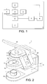
- Fig. 1 shows a schematic block diagram of a device 1 for preparing a frozen confection according to the present invention.
- the device 1 comprises a cooling element 6 which is adapted to receive the container.
- the cooling element 6 serves as a heat exchanger of the refrigeration system. It withdraws the heat energy from the container and its enclosed confection.
- the cooling element 6 can be flat or can provide a recess into which the container is inserted.
- the cooling element 6 further can have any possible shape being of the same size, smaller or larger than the container.
- the cooling element 6 further is made of a material which provides excellent heat transfer properties.
- the device 1 further comprises a cooling unit 8 which is adapted to cool the cooling element 6. Since the cooling element 6 comprises an excellent heat conductivity the container when being in touch with the cooling element 6 is cooled.
- the cooling unit 8 can comprise any refrigeration and/or circulatory heat transfer system to cool the cooling element 6 and consequently the container as rapidly as possible. Further a defrosting system can also be included into the cooling unit 8 in order to minimize the frosting of the cooling element 6. Either a defrosting plate or a dryer air circulation using dehumidified air can be provided.
- the device 1 can comprise a defrosting system to minimize the frosting of any heat exchanging parts.
- the defrosting system is for example a hot gas defrost system that can comprise a switchable reversed compressor gas flow valve, a defrosting plate and/or a dry air circulation system with the humidified air.
- an automatic defrosting mechanism is provided by means of a reversible and controllable hot gas defrost valve which allows just sufficient quantities of hot gas from the cooling unit 8 to be forced into or next to the cooling element 6 such that the temperature of the heat exchange surface is raised to a predetermined temperature and the surface is defrosted.
- thermoelectric Peltier
- an automatic electronic switch will reverse the polarity of the electric circuit powering the thermoelectric devices such that cool and hot -sides of the devices are reversed and the cool-side of the thermoelectric devices becomes the hot-side and the hot-side becomes cold-side such that the temperature of the heat exchange surface is raised to a predetermined temperature and the surface is defrosted.
- the device further comprises a processing unit 3 which is adapted to apply the necessary mechanical force to the container when inserted into the device 1.
- the processing unit 3 preferably comprises a scraping, grinding or kneading assembly which externally processes the ingredients inside the container through the flexible container walls and scrapes, grinds or kneads the ingredients during cooling.
- the scraping, grinding or kneading assembly facilitates the mixing and causes shear forces within the ingredient mix during the cooling (and therefore also freezing) process. The latter is the key for achieving a good overrun of the final frozen product.
- the processing unit 3 can consist of a combination of one or more shapes, including hard spherical balls, cones, polygonal scraping blocks or the like. These objects can be fixed, freely moving or forced to move.
- the processing unit 3 is provided to scrape the surface of the container during the cooling of the container and to also develop the overrun of the final frozen confection product.
- the device 1 can comprise an opening unit 4 which is adapted to open the container after the preparation of the frozen confection, so that the frozen confection can be dispensed through the opening from the container.
- the opening unit 4 can also be omitted and a manual opening by a user can be provided.
- the device 1 further comprises a dispensing unit 5 which is adapted to dispense the prepared frozen confection from the container after the container has been opened either manually by a user or by the opening unit 4.
- the dispensing unit 5 thus forces the freshly made frozen confection through the opening of the container.
- the device 1 comprises a motor 2.
- the motor 2 is adapted to drive the processing unit 3 and to provide the necessary force or torque, so that the necessary movement and force can be provided to apply the mechanical force to the container.
- the motor 2 can also be omitted and there can be provided means, e. g. a crank handle, which allow the user to manually drive the processing unit 3.
- the motor 2 can also be used to drive the opening unit 4 and/or the dispensing unit 5.
- the motor 2 can also be used to drive the opening unit 4 and/or the dispensing unit 5.
- one or both units are only activated manually or by other means such as the use of additional motors as required to perform separate operations individually for processing and dispensing.
- the device 1 comprises an activation mechanism 9 which is adapted to activate the whole processing.
- the activation mechanism 9 starts the cooling by the cooling unit 8 and in case that a motor 2 is provided the activation mechanism starts the motor 2. If the motor is omitted or if the motor only drives a part of the units, then the activation mechanism can be directly connected with the respective units and activate the respective units directly.
- a retainer 7 which is adapted to receive the frozen confection when dispensed from the container.
- the retainer 7 is of course removable from the device 1.
- Fig. 2 and 3 show a preferred embodiment of a device for preparing a frozen confection according to the present invention. It is to be noted that fig. 2 and 3 are only examples and that the present invention comprises also every other structure and shape of a device for preparing a frozen confection falling under the scope of the present claims.
- Fig. 2 shows a perspective side view of a device 1 according to the present invention.
- Fig. 3 shows a cross section of a device 1 according to the present invention.
- the device 1 comprises a casing 54 which houses several components of the device 1.
- a condenser 10 and a compressor 11 in the case of conventional vapour compression refrigeration, which form the cooling unit 8.
- a support 52 is provided which is adapted to receive a retainer 7 thereon, into which the prepared frozen confection 17 can be filled.
- the support 52 in one embodiment can also be cooled by the cooling unit 8.
- the protruding portion 16 can comprise a recess 53, so that the surface of the cooling element 6 is lower than the surface of the protruding portion 16. Into this recess 53 a container 20 can then be inserted.
- the cooling element 6 can have any possible shape, which is adapted to receive and cool a corresponding container 20.
- the cooling element can be flat or of a bowl-like shape adapted to receive the container 20 therein.
- the cooling element 20 can have a circular, elliptical or any other type of roundish shape being either a substantially flat plate or being a hollow receptacle, e.g. a hollow cylinder or the like.
- the cooling element 6 can have a rectangular or any other shape being either a flat plat or a hollow receptacle.
- the shape of the cooling element is adapted to the shape of the container 20 to allow for a good heat exchange and cooling.
- a container 20 is exemplary shown in fig. 3 .
- the container 20 contains ingredients 15 for producing a frozen confection when being cooled and mechanically forced.
- the container 20 can be positioned onto the cooling element 6.
- a recess 53 is provided and according to a preferred embodiment the container 20 when posed onto the cooling element 6 does not protrude the protruding portion 16.
- the device 1 further comprises the processing unit 3 and the dispensing unit 5. In a preferred embodiment those two units are integrated into one upper component 56 of the device 1.
- the processing unit 3 and the dispensing unit 5 are movable with respect to the protruding portion 16 and the cooling element 6. Specifically, the processing unit 3 can be moved away from the protruding portion 16, so that the container 20 can be placed onto the cooling element 6.
- the processing unit 3 can be moved into direction of the container 20, so that the processing unit 3 is in direct contact with the container 20.
- the shape of the processing unit 3 is adapted to the shape of the container 20 in order to enable the processing of all parts of the container 20.
- the dispensing unit 5 is also provided within the upper component 56 of the device 1, also the dispensing unit 5 is brought in contact with the container 20 and can then be activated after the frozen confection has been prepared.
- the processing unit 3 and the dispensing unit 5 are integrated into the upper component 56 which is movable with respect to the protruding portion 16 by means of a connector 13 and a lever 12.
- the lever 12 via pivots 14 is movably connected to the casing 54 and to the upper component 56. A part of the lever 12 protrudes the upper component 56 and can be grabbed by a customer.
- a connector 13 by pivots 14 is movably connected to the casing 54 and to the upper component 56 comprising the processing unit 3. If the lever 12 is moved, this results also in a movement of the processing unit 3 with respect to the protruding portion 16. By operating the lever 12 thereby the processing unit 3 can be placed onto the container 20 or removed therefrom.
- all components of the device 1 can be controlled electronically and automatically, e.g. by pressing one or more corresponding control buttons or switches.
- the user after having inserted the container 20 into the device can then activate the mechanism, and afterwards the processing unit 3 is automatically placed onto the container 20 and after preparation of the frozen confection the dispensing unit 5 is automatically activated.
- the cooling element 6 preferably comprises an aperture 27 through which the prepared frozen confection 17 can be dispensed into the retainer 7.
- the aperture 27 can also be provided within a part of the protruding portion 16.
- the aperture 27 can have different positions within the plate 6 depending on the type of the used container 20. In any case the aperture 27 has to be in line with an opening of the container 20 to allow the dispensing of the frozen confection 17 through the opening of the container 20 and through the aperture 27.
- the container comprises a flexible casing, so that when the processing unit 3 is activated, a mechanical force can be applied to the ingredients 15 within the container 20.
- the physical properties of the casing of the container 20 allow energy to be transferred from the ingredients 15 to an external source, i. e. heat energy to be transferred from the ingredients 15 to the cooling element 6.
- the ingredients preferably comprise a chilled or shelf-stable confection and a gaseous phase, e.g. air.
- a gaseous phase e.g. air.
- the amount of confection ranges from 50 to 70 % and the rest of the container is filled with gas.
- the ingredients 15 hereby provide a single portion of frozen confection 17.
- the single portion of chilled or shelf-stable confection mix is capable of producing between 80 to 200 ml of frozen confection.
- any other type of gas can be provided within the container 20 to allow for aeration and overrun.
- nitrogen can be provided within the container 20 for aseptic filling and extended shelf life.
- the container 20 is specifically made from materials with an erosion resistance and mechanically strong properties. Thin dimensions allow for good heat transfer properties.
- the container 20 is made from disposable and potentially recyclable materials.
- frozen confection is intended to refer to different types of frozen confection.
- Non limiting examples are ice cream, sorbet, sherbet, water ice, frozen yogurt, frozen dairy, soft ice, Mellorine, frozen custard, non-dairy frozen confection, milk ice, ice lolly, gelato or frozen jelly.
- the container 20 comprises a circular shape as shown in fig. 4a .
- the container 20 can have a ring-like shape with a gap 21 or alternatively a sealed surface in the middle of the container 20.
- the container can have a rectangular shape as shown in fig. 4c or can have a polygonal shape as shown in fig. 4d .
- the container 20 according to the present invention is not limited to the shown embodiments but comprises any other shape either with one or more gaps or without gap which fall under the scope of protection of the present invention.
- the container 20 alternatively or additionally can also have one or more sealed surfaces.
- the container 20 is moulded to its final design and comprises at least one part having therein the confection and optionally at least one part of sealed surfaces, which may form a shaped sleeve and which contain no confection. In addition to sealing the container 20 the sealed surfaces also allow to keep the container 20 in shape.
- the container 20 has a casing made of a flexible material, in a preferred embodiment means are provided to keep the container 20 in shape and/or leak tight. This ensures an equal distribution of the ingredients 15 between the cooling element 6 and the processing unit 3. Thereby, a uniform cooling and application of mechanical force to the ingredients 15 is assured.
- fig. 5a to 5d different possibilities of keeping the container 20 in a pre-defined shape are shown.
- the container shows a large surface to volume ratio for an efficient heat transfer.
- Fig. 5a shows an embodiment where on one or two sides of the flexible casing 25 an exoskeleton 22 is provided.
- the exoskeleton 22 comprises three bars being connected with each other at a central point of the container 20.
- the sealed surface is provided at the outer border of container.
- Fig. 5b shows a second embodiment, where a circumferential ring 23 is provided on one or two sides of the flexible casing 25 in order to keep the shape of the container 20.
- a sealed surface surrounding the container 20 can be provided for sealing the container 20 and keeping the container 20 in shape.
- an exoskeleton or a ring running along the outer diameter of the container 20 as well as a sealed surface can also be provided with different shapes of the container 20.
- Fig. 5c shows a further embodiment how the container 20 can be kept in shape when being inserted into the device 1.
- plugs 24 are provided on one side of the container 20, which are adapted to be inserted into corresponding holes provided in the cooling element 6.
- five bars 24 along the border of the container 20 are provided, but any other number and positioning of the bars 24 is possible.
- Fig. 5d shows a further embodiment of a container.
- the container comprises a central circular portion 30 having therein the confection.
- the central potion 30 is surrounded by a rectangular sealed surface or a border 31.
- This sealed surface in the present embodiment has two functions. On one hand the sealed surface seals the part of the container 20 comprising the confection and thereby keeps the container 20 leak tight. On the other, the sealed surface keeps the container 20 in shape.
- perforations 57 are provided within the sealed surface or the border 31 of the container 20, which are adapted to fit onto corresponding bars, pins or plugs on the device 1.
- a sealed surface is provided for sealing the container 20 and keeping the portion of the container 20 comprising the confection leak tight.
- the sealed surface can have a shape and/or provided at specific positions of the container 20 to keep the container in shape.
- an exoskeleton 22, a circumferential ring 23 or any other additional means for providing stability can be added to the container 20.
- the container comprises means for attaching the container 20 to the device 1, thereby also allowing to keep the container 20 in shape and to provide the necessary stability of the container 20 during the production of the frozen confection.
- Fig. 6a shows a first example how the container 20 can be put onto the cooling element 6.
- the container 20 comprises an opening 26 in the middle of the container 20.
- the opening 26 can also be provided at any other position, e.g. at the side of the container 20.
- the cooling element 6 comprises an aperture 27 which is positioned in such a way that the opening 26 of the container 20 can be inserted into the aperture 27 and/or is in line with the aperture 27.
- Fig. 6a hereby shows the case that the container 20 comprises an exoskeleton or a ring keeping the container 20 in shape, but this is an optional implementation.
- Fig. 6b shows a further embodiment of positioning the container 20 onto the cooling element 6.
- bars 24 as previously explained are protruding from the container 20 and can be inserted into corresponding holes 55 in the cooling element 6.
- the container 20 is fixedly hold to the cooling element 6 and keeps its shape when the processing unit 3 applies a mechanical force to the container 20.
- Fig. 6c shows a further embodiment of positions the container 20 onto the cooling element 6.
- the container 20 has a border 31 or sealed surface having therein perforations 57 which fit onto corresponding pins 58 attached to the device 1.
- the opening 26 is closed or sealed, so that during the cooling and the application of mechanical force by the processing unit 3 the ingredients 15 and/or the prepared frozen confection 17 can not leak from the container 20.
- the opening 26 can be opened, e. g. for removing a seal, or by breaking a seal or removing a plug, so that the frozen confection 17 can be dispensed from the container 20.
- the opening 26 is a sealed aperture or spout and can be either manually or automatically broken, torn, ruptured or the like.
- an opening unit 4 can be provided within the device 1 which automatically opens the container 20 after the preparation of the frozen confection 17.
- the user can approach the opening 26 and manually remove or break the seal.
- Fig. 7a shows a first embodiment where the opening 26 is provided in the middle of the container 20.
- Fig. 7b is a side view of the container and shows that the opening 26 is provided on one side of the container in the middle of the container 20 and protrudes the container 20.
- Fig. 7c shows a possible configuration how the dispensing of the prepared frozen confection 17 could be accomplished with a container having an opening 26 in the middle.
- flow lines 28 can be provided.
- the processing unit 3 and/or the dispensing unit 5 applies a movement in the direction as shown with arrow A.
- the flow lines 28 the frozen confection 17 is guided to the central opening 26 and dispensed from the container.
- This first embodiment thus proposes a flow lobe to the centre.
- Fig. 8a shows a second embodiment, where the opening 26 is provided on one side of the container 20 and near the boarder of the container 20.
- Fig. 8b shows a corresponding side view of the container 20.
- Fig. 8c shows one possible configuration how the frozen confection 17 could be dispensed from the container 20.
- a barrier 29 can be provided within the container near the opening 26 so that when the frozen confection 17 is forced into a direction as indicated by arrow B the frozen confection 17 is dispensed through the opening 26 since it can not go beyond the barrier 29.
- This second embodiment thus provides a flow lobe to the side.
- Fig. 9a shows a third embodiment of an opening 26 according to the present invention.
- the opening 26 is provided at the side of the container 20.
- the opening 26 is thus integrated in the boarder of the container 20 and thus provides an interior side orifice.
- Fig. 9c shows a possible configuration how the frozen confection 17 can be dispensed from the container 20.
- a transverse movement direction indicated by a bar included in the device 1 which moves into direction as shown with arrows C can force the frozen confection 17 out through the opening 26.
- the container 20 comprises a side opening 26 as shown in Fig. 8a and the frozen confection is dispensed from the container 10 by a bar moving transversely along the container as shown in Fig. 9c .
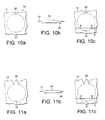
- Fig. 10a shows a further configuration of a container 20 according to the present invention comprising a fourth configuration of an opening 26.
- the container 20 comprises a central portion 30 which contains the ingredients 15 and a border 31.
- an exterior side orifice is provided as opening 26 and the opening 26 is provided within the boarder 31.
- Fig. 10b shows a side view and shows that the opening is provided on one side of the boarder 31 and protruding the boarder.
- the opening 26 allows the frozen confection 17 to exit the central portion 30 to flow through the opening and to be dispensed from the container 20.
- Fig. 10c again shows a possible configuration how the frozen confection 17 could be dispensed from the container 20. Again a transverse movement direction indicated by arrows D can force the frozen confection 17 out of the container 20.
- Fig. 11a shows a fifth embodiment of an opening 26 according to the present invention.
- This embodiment proposes a side spout within a container 20 having again a central portion 30 and a boarder 31.
- Fig. 11b shows a side view of the container 20.
- the opening is provided within the border 31 and thus provides a channel within the border 31 through which the frozen confection 17 can be dispensed.
- fig. 11c also in this configuration a transverse movement into the direction indicated with arrow E can dispense the prepared frozen confection 17 from the container.
- the dispensing unit 5 can be identical to the processing unit 3. If for example flow lines 28 as previously described are provided, then after the seal of the opening 26 has been broken or removed, the flow lines 28 guide the frozen confection 17 to the opening 26.
- the dispensing unit 5 can be provided as separate dispensing unit and provided within the same upper component 56 as the processing unit 3.
- the dispensing unit 5 can be provided as separate component and partly or completely integrated in the protruding portion 16 or into any other component of the device 1 enabling the dispensing unit 5 to dispense the frozen confection 17 from the container.
- Fig. 12a shows a first embodiment of a dispensing mechanism according to the present invention.
- the container 20 comprises an opening 26 in the middle of the container.
- a flexible ring 32 is provided having two ends 32a, 32b.
- a force in direction F is applied to both ends 32a, 32b so that the ring 32 when applying the force reduces its diameter and thereby presses the frozen confection 17 towards the centre opening 26.
- Fig. 12b shows a second embodiment of a dispensing mechanism according to the present invention.
- the upper part of fig. 12b shows the case where the frozen confection 17 has been readily prepared within the container 20.
- the container 20 is provided on the cooling element 6.
- an inflatable balloon 34 is provided which is connected to a gas supply 34a, e. g. a supply of air or any other gas.
- a barrier 33 is provided which is adapted to hold out the force of the inflatable balloon 34 when being inflated.
- the bottom part of fig. 12b shows the case where the inflatable balloon 34 is inflated and thereby squeezes the container 20, so that the frozen confection 17 is dispensed through the opening 26.
- the embodiment using an inflatable balloon can also be used with any other type of opening, i. e. an opening provided in the middle, at the side or within a boarder 31 of the container 20.
- Fig. 12c shows a further embodiment of a dispensing mechanism according to the present invention.
- the cooling element 6 has a concave shape and the upper part of fig. 12c shows the case where the frozen confection 17 is readily prepared and contained within the container 20.
- a convex plate 35 is provided which can be forced down onto the container 20 and which has a shape substantially equal to the shape of the cooling element 6. As shown in the lower part of fig. 12c , when the convex plate 35 is pushed down onto the concave container 20, the container 20 is squeezed and the frozen confection is dispensed through the opening 26 from the container 20.
- Fig. 12d shows a further embodiment of a dispensing mechanism according to the present invention.
- the container 20 is provided between a for example magnetic barrier 36 and a magnetic plate 37.
- Magnetic plate 37 comprises two parts which are provided on both sides of the opening 26 of the container 20. If the mechatronic system is activated then as shown in the lower part of fig. 12d the plates are pushed towards the magnetic barrier 36 and thereby the container 20 is squeezed so that the frozen confection 17 is dispensed from the container.
- Fig. 12e shows a further embodiment of a dispensing mechanism according to the present invention.
- a barrier 38 slides from the side to the centre of the container 20.
- a pair of cones 39 then squeezes the flexible container casing, rotates in direction as shown by arrow G and therefore forces the frozen confection towards the outlet 26 near the barrier 38.
- Fig. 12f shows a further embodiment of a dispensing mechanism according to the present invention.
- a pair of cones is provided, but in this embodiment the pair of cones lies on the same side of the container casing and comprises a first processing cone 40 and a second processing cone 41.
- the cones can be split and moved independently from each other. This is shown in the lower picture of fig. 12f .
- the first processing cone 40 can either be maintained at a fixed position or moved in reverse direction to the second processing cone 41 which is moved in direction indicated by arrow H.
- For dispensing cone 40 remains stationary and builds a barrier for the confection while cone 41 continues to move and forces the frozen confection towards cone 40 and the opening 26.
- the opening 26 is provided at the side or at the border of the container 20 so that the frozen confection 17 can be forced through the side opening.
- Fig. 12g shows a further embodiment of a dispensing mechanism according to the present invention.
- a partial sheet 42 is provided at the bottom of the container 20, i.e. in-between the two sides of the container 20.
- the partial sheet 42 has a fixed side 43 which is fixedly attached to the bottom of the container 20.
- the partial sheet 42 further has an open side 44 which is not fixedly attached to the bottom of the container 20, so that the partial sheet 41 forms an outlet channel.
- the partial sheet 42 covers the opening 26. If now during the preparation of the frozen confection 17 the processing unit 3 moves the ingredients 15 into a direction as indicated with arrow J, then the partial sheet 42 is pressed onto the opening 26 and, so that the ingredients 15 run across the partial sheet 42 without any effect.
- the movement direction of the processing unit 3 and/or the dispensing unit 5 is reversed and the frozen confection 17 is moved into the direction as indicated with arrow K.
- the frozen confection 17 thereby approaches the partial sheet 42 from the side where the partial sheet 42 has the open side 44 so that as shown in the bottom part of fig. 12c the open side 44 is pushed upwards into direction shown with arrows L so that the opening 26 is not covered anymore and the frozen confection 17 will enter the outlet channel formed by the partial sheet. Due to the fixed side 43 of the pouch the frozen confection 17 will be forced to be dispensed through the opening 26.
- Fig. 12h shows a further embodiment of a dispensing mechanism according to the present invention.
- flow lines 28 can be provided within the container 20 forcing the frozen confection into a specific direction as indicated with arrow N in case that the processing unit 3 and/or the dispensing unit 5 moves the frozen confection 17 into a direction as indicated with arrow M.
- Fig. 12i shows a further embodiment of a dispensing mechanism according to the present invention.
- the container 20 is put into a sealed chamber 45 which can be hermetically sealed and is connected to a receptacle 46.
- a vacuum pump 48 via a conductor 47 is connected to the container and sucks out the frozen confection 17 from the container 20 into the receptacle 46.
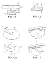
- Fig. 12j shows a further embodiment of a dispensing mechanism according to the present invention.
- a cover plate 59 is provided onto the container 20.
- the cover plate 59 can also be omitted and instead the processing unit 3 can be used as cover plate.
- the container 20 is then rotated rapidly in direction as shown by arrow P and by centrifugal force the frozen confection is pressed out of the container 20.
- Fig. 12k shows a further embodiment of a dispensing mechanism according to the present invention.
- a wring cone 49 is provided which is adapted to role or wring the flexible container 20 so that the frozen confection 17 is pressed out of the opening 26.
- This is shown in the bottom part of fig. 12k , where the rolled container 20 is shown and a dashed line 50 indicates the former shape of the container 20.
- Fig. 12l shows a further embodiment of a dispensing mechanism according to the present invention.
- two rotatable cones 51 are provided and the container 20 is clamped between the rotatable cones 51.
- the rotatable cones 51 are then rotated in opposite direction so that the container 20 wanders through the rotatable cones so that the frozen confection 17 can be dispensed through a side opening 26 of the container 20.
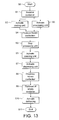
- Fig. 13 shows a flow chart with an overview over the different steps for preparing a frozen confection 17 according to the present invention.
- step S0 The process starts in step S0.
- step S1 the container 20 is received by the device 1, i. e. is put onto the cooling element 6.
- step S2 the cooling unit 8 is activated and at the same time in step S3 the processing unit 3 is activated.
- step S4 the frozen confection 17 is produced by cooling the ingredients 15 and applying a mechanical force to the container 20.
- step S5 the processing unit is stopped and in step S6 the opening unit 4 can be activated in order to open the container 20.
- this step can also be omitted and accomplished manually by a customer.
- step S7 the dispensing unit 5 is then activated and in the following step S8 the frozen confection 17 is dispensed from the container 20.
- step S9 the empty container 20 is then removed from the device 1.
- a defrosting step S10 can be accomplished by activating the defrosting system, if present. This has the advantage that it is assured that there is no frosting on the container holder surface in readiness to receive the next container.
- the defrosting step can also be provided between or during other steps and/or between or during a plurality of steps. But in the preferred embodiment defrosting is accomplished after each production cycle. The process ends in step S11 and the device 1 is thus ready for receiving a new container and preparing a further single portion of freshly made frozen confection.
- the present invention thus enables the preparation of a frozen confection, which can be freshly prepared in single portions by a closed system.
- the containers provide a pre-dosed packaging containing all the necessary ingredients for preparing the frozen confection.
- the frozen confection is prepared inside the container.
- the present invention it is further possible to prepare several different types of frozen confections in a short time. Since the container is dispensable and does not need to be cleaned and since most parts of the device do not come into contact with the frozen confection, the handling is simplified and the need for cleaning is reduced.
Landscapes
- Engineering & Computer Science (AREA)
- Life Sciences & Earth Sciences (AREA)
- Chemical & Material Sciences (AREA)
- Food Science & Technology (AREA)
- Polymers & Plastics (AREA)
- Manufacturing & Machinery (AREA)
- Mechanical Engineering (AREA)
- Confectionery (AREA)
Abstract
The present invention relates to a container (20) designed for being inserted into a device (1) for preparing a frozen confection (17), said container (20) comprising a sealed flexible casing (25) and said container (20) containing ingredients (15) for producing a frozen confection (17) when being cooled and mechanically forced.
The present invention further relates to a device (1) for preparing a frozen confection (17) from a container (20) inserted into the device (1). The present invention further relates to a method for preparing a frozen confection.
Description
- The present invention relates to a container designed for being inserted into a device for preparing a frozen confection and to a device for preparing a frozen confection. Specifically, the present invention relates to the field of preparing a single serving freshly made frozen confection.
- Current domestic ice cream makers on the market rely on scraped heat exchangers using a horizontal or tubular bowl. These systems utilize conventional compression cooling technology with CFC, HFC, HC, CO2, other chemical refrigerants or thermoelectric (peltier) systems. Such systems are for example disclosed in documents
W08606936 US4540288 ,US6267049 ,W02006043298 ,W02004089104 ,US5549042 ,US5823675 ,US5823675 ,US6298668 ,JP2001017090 US6863916 ,W09611583 DE3921115 ,W08807330 BE901125 EP106814 EP0179027 ,US4583863 ,US 2004045312 , orUS6041614 . - These ice cream makers produce large volumes of ice cream ranging from 0,5 l to 1 l in a time period of 20 to 60 minutes. The ice cream must then be removed from the bowl manually or at best requires overall cleaning cycles after dispensing.
- It is therefore an object of the present invention to improve the prior art. Specifically, it is an object of the present invention to provide a possibility to prepare freshly made single portions of frozen confection without the need for cleaning cycles. Furthermore, it is an object of the present invention to provide a possibility to prepare freshly made single portions of frozen confection in a short period of time compared to the existing ice cream maker machines.
- This object is solved by the independent claims.
- Further features and embodiments are subject matter of the dependent claims.
- Further features, advantages and objects of the present invention will become evident by means of the figures of the enclosed drawings as well as by the following detailed explanation of illustrative-only embodiments of the present invention.
-
Fig. 1 shows a schematic block diagram of the components of a device for preparing a frozen confection according to the present invention, -
fig. 2 and3 show different views of a preferred embodiment of a device for preparing a frozen confection according to the present invention, -
fig. 4a to 4d show different shapes of a container according to the present invention, -
fig. 5a to 5d show different embodiments of stabilizing the container according to the present invention, -
fig. 6a to 6c show different embodiments of inserting the container into the device for preparing a frozen confection according to the present invention, -
fig. 7a to 7c show a first embodiment of an opening unit within a container according to the present invention, -
fig. 8a to 8c show a second embodiment of an opening unit within a container according to the present invention, -
fig. 9a to 9c show a third embodiment of an opening unit within a container according to the present invention, -
fig. 10a to 10c show a fourth embodiment of an opening unit within a container according to the present invention, -
fig. 11a to 11c show a fifth embodiment of an opening unit within a container according to the present invention, -
fig. 12a to 12l show different embodiments of a dispensing mechanism according to the present invention, and -
fig. 13 is a flow chart showing schematically the process steps for preparing a frozen confection according to the present invention. - The present invention proposes a container which is designed for being inserted into a device for preparing a frozen confection. The container has a flexible casing, which has an opening that can be closed or sealed. The container comprises ingredients within the flexible casing for producing a frozen confection when being cooled and mechanically forced simultaneously. The ingredients enable the preparation of frozen confection in situ.
- The present invention further relates to a device for preparing a frozen confection when the container is inserted into the device. The device is adapted to cool the container and to apply a mechanical force to the container.
- Since the container has a flexible casing the mechanical force is transferred through the container walls and consequently applied to the ingredients within the container. Since the material of the container further preferably has a low thickness, so that the heat transfer resistance across the casing is minimal, the ingredients within the container are effectively cooled. The material of the container can comprise one or more material parts or material components.
- The present invention thus provides a device, which comprises means to receive the container, to cool the container and to apply a mechanical force to the container, so that by cooling and applying a mechanical force to the ingredients within the container a frozen confection can be prepared.
-
Fig. 1 shows a schematic block diagram of adevice 1 for preparing a frozen confection according to the present invention. Thedevice 1 comprises acooling element 6 which is adapted to receive the container. Thecooling element 6 serves as a heat exchanger of the refrigeration system. It withdraws the heat energy from the container and its enclosed confection. Thecooling element 6 can be flat or can provide a recess into which the container is inserted. Thecooling element 6 further can have any possible shape being of the same size, smaller or larger than the container. Thecooling element 6 further is made of a material which provides excellent heat transfer properties. - The
device 1 further comprises acooling unit 8 which is adapted to cool thecooling element 6. Since thecooling element 6 comprises an excellent heat conductivity the container when being in touch with thecooling element 6 is cooled. Thecooling unit 8 can comprise any refrigeration and/or circulatory heat transfer system to cool thecooling element 6 and consequently the container as rapidly as possible. Further a defrosting system can also be included into thecooling unit 8 in order to minimize the frosting of thecooling element 6. Either a defrosting plate or a dryer air circulation using dehumidified air can be provided. - Optionally, the
device 1 can comprise a defrosting system to minimize the frosting of any heat exchanging parts. The defrosting system is for example a hot gas defrost system that can comprise a switchable reversed compressor gas flow valve, a defrosting plate and/or a dry air circulation system with the humidified air. - In case defrosting of the internal heat exchange surface is necessary and the
cooling unit 8 is conventional vapour compression/evaporation, an automatic defrosting mechanism is provided by means of a reversible and controllable hot gas defrost valve which allows just sufficient quantities of hot gas from thecooling unit 8 to be forced into or next to thecooling element 6 such that the temperature of the heat exchange surface is raised to a predetermined temperature and the surface is defrosted. - In case defrosting of the internal heat exchange surface is necessary and the
cooling unit 8 is thermoelectric (peltier) powered, an automatic electronic switch will reverse the polarity of the electric circuit powering the thermoelectric devices such that cool and hot -sides of the devices are reversed and the cool-side of the thermoelectric devices becomes the hot-side and the hot-side becomes cold-side such that the temperature of the heat exchange surface is raised to a predetermined temperature and the surface is defrosted. - The device further comprises a
processing unit 3 which is adapted to apply the necessary mechanical force to the container when inserted into thedevice 1. Theprocessing unit 3 preferably comprises a scraping, grinding or kneading assembly which externally processes the ingredients inside the container through the flexible container walls and scrapes, grinds or kneads the ingredients during cooling. In addition, the scraping, grinding or kneading assembly facilitates the mixing and causes shear forces within the ingredient mix during the cooling (and therefore also freezing) process. The latter is the key for achieving a good overrun of the final frozen product. - The
processing unit 3 can consist of a combination of one or more shapes, including hard spherical balls, cones, polygonal scraping blocks or the like. These objects can be fixed, freely moving or forced to move. Theprocessing unit 3 is provided to scrape the surface of the container during the cooling of the container and to also develop the overrun of the final frozen confection product. - Optionally, the
device 1 can comprise anopening unit 4 which is adapted to open the container after the preparation of the frozen confection, so that the frozen confection can be dispensed through the opening from the container. Alternatively, theopening unit 4 can also be omitted and a manual opening by a user can be provided. - The
device 1 further comprises adispensing unit 5 which is adapted to dispense the prepared frozen confection from the container after the container has been opened either manually by a user or by theopening unit 4. The dispensingunit 5 thus forces the freshly made frozen confection through the opening of the container. - In a preferred embodiment the
device 1 comprises amotor 2. Themotor 2 is adapted to drive theprocessing unit 3 and to provide the necessary force or torque, so that the necessary movement and force can be provided to apply the mechanical force to the container. In an alternative embodiment, themotor 2 can also be omitted and there can be provided means, e. g. a crank handle, which allow the user to manually drive theprocessing unit 3. - In case that a
motor 2 is provided themotor 2 can also be used to drive theopening unit 4 and/or thedispensing unit 5. Alternatively, one or both units are only activated manually or by other means such as the use of additional motors as required to perform separate operations individually for processing and dispensing. - Additionally, the
device 1 comprises anactivation mechanism 9 which is adapted to activate the whole processing. Theactivation mechanism 9 starts the cooling by thecooling unit 8 and in case that amotor 2 is provided the activation mechanism starts themotor 2. If the motor is omitted or if the motor only drives a part of the units, then the activation mechanism can be directly connected with the respective units and activate the respective units directly. - Also shown in
fig. 1 is aretainer 7 which is adapted to receive the frozen confection when dispensed from the container. Theretainer 7 is of course removable from thedevice 1. -
Fig. 2 and3 show a preferred embodiment of a device for preparing a frozen confection according to the present invention. It is to be noted thatfig. 2 and3 are only examples and that the present invention comprises also every other structure and shape of a device for preparing a frozen confection falling under the scope of the present claims. -
Fig. 2 shows a perspective side view of adevice 1 according to the present invention.Fig. 3 shows a cross section of adevice 1 according to the present invention. - The
device 1 comprises acasing 54 which houses several components of thedevice 1. Provided within thecasing 54 are acondenser 10 and a compressor 11 (in the case of conventional vapour compression refrigeration), which form thecooling unit 8. At the bottom part of the casing 54 asupport 52 is provided which is adapted to receive aretainer 7 thereon, into which the preparedfrozen confection 17 can be filled. Thesupport 52 in one embodiment can also be cooled by thecooling unit 8. - Above the
support 52 and in parallel to the support 52 a part of thecasing 54 is protruding and forms a protrudingportion 16 into which thecooling element 6 is integrated, which in the preferred embodiment has the shape of a plate. As shown infig. 2 the protrudingportion 16 can comprise arecess 53, so that the surface of thecooling element 6 is lower than the surface of the protrudingportion 16. Into this recess 53 acontainer 20 can then be inserted. - It is to be noted that the
cooling element 6 according to the present invention can have any possible shape, which is adapted to receive and cool acorresponding container 20. The cooling element can be flat or of a bowl-like shape adapted to receive thecontainer 20 therein. Thecooling element 20 can have a circular, elliptical or any other type of roundish shape being either a substantially flat plate or being a hollow receptacle, e.g. a hollow cylinder or the like. Alternatively, thecooling element 6 can have a rectangular or any other shape being either a flat plat or a hollow receptacle. In any case, the shape of the cooling element is adapted to the shape of thecontainer 20 to allow for a good heat exchange and cooling. - A
container 20 is exemplary shown infig. 3 . Thecontainer 20 containsingredients 15 for producing a frozen confection when being cooled and mechanically forced. As indicated by arrow R thecontainer 20 can be positioned onto thecooling element 6. In case that arecess 53 is provided and according to a preferred embodiment thecontainer 20 when posed onto thecooling element 6 does not protrude the protrudingportion 16. - The
device 1 further comprises theprocessing unit 3 and thedispensing unit 5. In a preferred embodiment those two units are integrated into one upper component 56 of thedevice 1. Theprocessing unit 3 and thedispensing unit 5 are movable with respect to the protrudingportion 16 and thecooling element 6. Specifically, theprocessing unit 3 can be moved away from the protrudingportion 16, so that thecontainer 20 can be placed onto thecooling element 6. - Afterwards, the
processing unit 3 can be moved into direction of thecontainer 20, so that theprocessing unit 3 is in direct contact with thecontainer 20. The shape of theprocessing unit 3 is adapted to the shape of thecontainer 20 in order to enable the processing of all parts of thecontainer 20. In case that the dispensingunit 5 is also provided within the upper component 56 of thedevice 1, also thedispensing unit 5 is brought in contact with thecontainer 20 and can then be activated after the frozen confection has been prepared. - In the embodiment shown in
fig. 2 and3 , theprocessing unit 3 and thedispensing unit 5 are integrated into the upper component 56 which is movable with respect to the protrudingportion 16 by means of aconnector 13 and alever 12. Thelever 12 viapivots 14 is movably connected to thecasing 54 and to the upper component 56. A part of thelever 12 protrudes the upper component 56 and can be grabbed by a customer. Likewise, aconnector 13 bypivots 14 is movably connected to thecasing 54 and to the upper component 56 comprising theprocessing unit 3. If thelever 12 is moved, this results also in a movement of theprocessing unit 3 with respect to the protrudingportion 16. By operating thelever 12 thereby theprocessing unit 3 can be placed onto thecontainer 20 or removed therefrom. - It is further possible to provide an additional mechanism to provide a two-step operation of the
lever 12. After placing thecontainer 20 onto thecooling element 6, the user by a very light force is enabled to position theprocessing unit 3 onto thecontainer 20. For moving thelever 12 further the user would have to exceed a predefined force. After the preparation of the frozen confection, then the user has to exceed said specific amount of force to further push thelever 12 in order to activate thedispensing unit 5. - In an alternative embodiment, all components of the
device 1 can be controlled electronically and automatically, e.g. by pressing one or more corresponding control buttons or switches. The user after having inserted thecontainer 20 into the device can then activate the mechanism, and afterwards theprocessing unit 3 is automatically placed onto thecontainer 20 and after preparation of the frozen confection thedispensing unit 5 is automatically activated. - The
cooling element 6 preferably comprises anaperture 27 through which the preparedfrozen confection 17 can be dispensed into theretainer 7. Alternatively , theaperture 27 can also be provided within a part of the protrudingportion 16. Theaperture 27 can have different positions within theplate 6 depending on the type of the usedcontainer 20. In any case theaperture 27 has to be in line with an opening of thecontainer 20 to allow the dispensing of thefrozen confection 17 through the opening of thecontainer 20 and through theaperture 27. - In the following, different embodiments of the container will be explained in more detail. Generally, the container comprises a flexible casing, so that when the
processing unit 3 is activated, a mechanical force can be applied to theingredients 15 within thecontainer 20. The physical properties of the casing of thecontainer 20 allow energy to be transferred from theingredients 15 to an external source, i. e. heat energy to be transferred from theingredients 15 to thecooling element 6. - The ingredients preferably comprise a chilled or shelf-stable confection and a gaseous phase, e.g. air. In a preferred embodiment the amount of confection ranges from 50 to 70 % and the rest of the container is filled with gas. The
ingredients 15 hereby provide a single portion offrozen confection 17. - Specifically, the single portion of chilled or shelf-stable confection mix is capable of producing between 80 to 200 ml of frozen confection. Instead of air also any other type of gas can be provided within the
container 20 to allow for aeration and overrun. Alternatively or additionally, nitrogen can be provided within thecontainer 20 for aseptic filling and extended shelf life. - The
container 20 is specifically made from materials with an erosion resistance and mechanically strong properties. Thin dimensions allow for good heat transfer properties. - In a preferred embodiment the
container 20 is made from disposable and potentially recyclable materials. - When used in the present invention the term "frozen confection" is intended to refer to different types of frozen confection. Non limiting examples are ice cream, sorbet, sherbet, water ice, frozen yogurt, frozen dairy, soft ice, Mellorine, frozen custard, non-dairy frozen confection, milk ice, ice lolly, gelato or frozen jelly.
- In
fig. 4a to 4d different possible but not limiting shapes of thecontainer 20 are shown. In a preferred embodiment thecontainer 20 comprises a circular shape as shown infig. 4a . In an alternative embodiment as shown infig. 4b thecontainer 20 can have a ring-like shape with agap 21 or alternatively a sealed surface in the middle of thecontainer 20. - Alternatively, the container can have a rectangular shape as shown in
fig. 4c or can have a polygonal shape as shown infig. 4d . - The
container 20 according to the present invention is not limited to the shown embodiments but comprises any other shape either with one or more gaps or without gap which fall under the scope of protection of the present invention. Thecontainer 20 alternatively or additionally can also have one or more sealed surfaces. - Generally the
container 20 is moulded to its final design and comprises at least one part having therein the confection and optionally at least one part of sealed surfaces, which may form a shaped sleeve and which contain no confection. In addition to sealing thecontainer 20 the sealed surfaces also allow to keep thecontainer 20 in shape. - Since the
container 20 has a casing made of a flexible material, in a preferred embodiment means are provided to keep thecontainer 20 in shape and/or leak tight. This ensures an equal distribution of theingredients 15 between the coolingelement 6 and theprocessing unit 3. Thereby, a uniform cooling and application of mechanical force to theingredients 15 is assured. Infig. 5a to 5d different possibilities of keeping thecontainer 20 in a pre-defined shape are shown. Typically, the container shows a large surface to volume ratio for an efficient heat transfer. -
Fig. 5a shows an embodiment where on one or two sides of theflexible casing 25 anexoskeleton 22 is provided. In the embodiment shown infig. 5a theexoskeleton 22 comprises three bars being connected with each other at a central point of thecontainer 20. In this case, preferably, the sealed surface is provided at the outer border of container. -
Fig. 5b shows a second embodiment, where acircumferential ring 23 is provided on one or two sides of theflexible casing 25 in order to keep the shape of thecontainer 20. Alternatively or additionally, a sealed surface surrounding thecontainer 20 can be provided for sealing thecontainer 20 and keeping thecontainer 20 in shape. - It is to be noted that an exoskeleton or a ring running along the outer diameter of the
container 20 as well as a sealed surface can also be provided with different shapes of thecontainer 20. -
Fig. 5c shows a further embodiment how thecontainer 20 can be kept in shape when being inserted into thedevice 1. In this embodiment plugs 24 are provided on one side of thecontainer 20, which are adapted to be inserted into corresponding holes provided in thecooling element 6. In the embodiment shown infig. 5c fivebars 24 along the border of thecontainer 20 are provided, but any other number and positioning of thebars 24 is possible. -
Fig. 5d shows a further embodiment of a container. In this embodiment the container comprises a centralcircular portion 30 having therein the confection. Thecentral potion 30 is surrounded by a rectangular sealed surface or aborder 31. This sealed surface in the present embodiment has two functions. On one hand the sealed surface seals the part of thecontainer 20 comprising the confection and thereby keeps thecontainer 20 leak tight. On the other, the sealed surface keeps thecontainer 20 in shape. - In this embodiment,
perforations 57 are provided within the sealed surface or theborder 31 of thecontainer 20, which are adapted to fit onto corresponding bars, pins or plugs on thedevice 1. - To summarize, preferably a sealed surface is provided for sealing the
container 20 and keeping the portion of thecontainer 20 comprising the confection leak tight. The sealed surface can have a shape and/or provided at specific positions of thecontainer 20 to keep the container in shape. For keeping the container in shape, alternatively or additionally, anexoskeleton 22, acircumferential ring 23 or any other additional means for providing stability can be added to thecontainer 20. - In a further embodiment, the container comprises means for attaching the
container 20 to thedevice 1, thereby also allowing to keep thecontainer 20 in shape and to provide the necessary stability of thecontainer 20 during the production of the frozen confection. -
Fig. 6a shows a first example how thecontainer 20 can be put onto thecooling element 6. In this exemplary embodiment thecontainer 20 comprises anopening 26 in the middle of thecontainer 20. Theopening 26 can also be provided at any other position, e.g. at the side of thecontainer 20. Thecooling element 6 comprises anaperture 27 which is positioned in such a way that theopening 26 of thecontainer 20 can be inserted into theaperture 27 and/or is in line with theaperture 27.Fig. 6a hereby shows the case that thecontainer 20 comprises an exoskeleton or a ring keeping thecontainer 20 in shape, but this is an optional implementation. -
Fig. 6b shows a further embodiment of positioning thecontainer 20 onto thecooling element 6. In this embodiment bars 24 as previously explained are protruding from thecontainer 20 and can be inserted into correspondingholes 55 in thecooling element 6. Thereby, thecontainer 20 is fixedly hold to thecooling element 6 and keeps its shape when theprocessing unit 3 applies a mechanical force to thecontainer 20. -
Fig. 6c shows a further embodiment of positions thecontainer 20 onto thecooling element 6. In this embodiment thecontainer 20 has aborder 31 or sealed surface having thereinperforations 57 which fit onto correspondingpins 58 attached to thedevice 1. - It is to be noted, that any features of one aforementioned embodiment can be implemented into on or more other embodiments where possible and the present invention is not limited to the above described combinations of features.
- In the following, different embodiments of the
opening 26 provided within thecontainer 20 are explained. Theopening 26 is closed or sealed, so that during the cooling and the application of mechanical force by theprocessing unit 3 theingredients 15 and/or the preparedfrozen confection 17 can not leak from thecontainer 20. After the preparation of thefrozen convection 17, theopening 26 can be opened, e. g. for removing a seal, or by breaking a seal or removing a plug, so that thefrozen confection 17 can be dispensed from thecontainer 20. Generally, theopening 26 is a sealed aperture or spout and can be either manually or automatically broken, torn, ruptured or the like. As previously explained, either anopening unit 4 can be provided within thedevice 1 which automatically opens thecontainer 20 after the preparation of thefrozen confection 17. Alternatively, the user can approach theopening 26 and manually remove or break the seal. -
Fig. 7a shows a first embodiment where theopening 26 is provided in the middle of thecontainer 20.Fig. 7b is a side view of the container and shows that theopening 26 is provided on one side of the container in the middle of thecontainer 20 and protrudes thecontainer 20. -
Fig. 7c shows a possible configuration how the dispensing of the preparedfrozen confection 17 could be accomplished with a container having anopening 26 in the middle. Within thecontainer 20flow lines 28 can be provided. For dispensing thefrozen confection 17 theprocessing unit 3 and/or thedispensing unit 5 applies a movement in the direction as shown with arrow A. Thereby by theflow lines 28 thefrozen confection 17 is guided to thecentral opening 26 and dispensed from the container. This first embodiment thus proposes a flow lobe to the centre. -
Fig. 8a shows a second embodiment, where theopening 26 is provided on one side of thecontainer 20 and near the boarder of thecontainer 20.Fig. 8b shows a corresponding side view of thecontainer 20.Fig. 8c shows one possible configuration how thefrozen confection 17 could be dispensed from thecontainer 20. Abarrier 29 can be provided within the container near theopening 26 so that when thefrozen confection 17 is forced into a direction as indicated by arrow B thefrozen confection 17 is dispensed through theopening 26 since it can not go beyond thebarrier 29. This second embodiment thus provides a flow lobe to the side. -
Fig. 9a shows a third embodiment of anopening 26 according to the present invention. In this case theopening 26 is provided at the side of thecontainer 20. Theopening 26 is thus integrated in the boarder of thecontainer 20 and thus provides an interior side orifice.Fig. 9c shows a possible configuration how thefrozen confection 17 can be dispensed from thecontainer 20. A transverse movement direction indicated by a bar included in thedevice 1 which moves into direction as shown with arrows C can force thefrozen confection 17 out through theopening 26. - In a preferred embodiment, the
container 20 comprises aside opening 26 as shown inFig. 8a and the frozen confection is dispensed from thecontainer 10 by a bar moving transversely along the container as shown inFig. 9c . -
Fig. 10a shows a further configuration of acontainer 20 according to the present invention comprising a fourth configuration of anopening 26. In this case thecontainer 20 comprises acentral portion 30 which contains theingredients 15 and aborder 31. In this case an exterior side orifice is provided asopening 26 and theopening 26 is provided within theboarder 31. -
Fig. 10b shows a side view and shows that the opening is provided on one side of theboarder 31 and protruding the boarder. Theopening 26 allows thefrozen confection 17 to exit thecentral portion 30 to flow through the opening and to be dispensed from thecontainer 20.Fig. 10c again shows a possible configuration how thefrozen confection 17 could be dispensed from thecontainer 20. Again a transverse movement direction indicated by arrows D can force thefrozen confection 17 out of thecontainer 20. -
Fig. 11a shows a fifth embodiment of anopening 26 according to the present invention. This embodiment proposes a side spout within acontainer 20 having again acentral portion 30 and aboarder 31.Fig. 11b shows a side view of thecontainer 20. As can be seen, the opening is provided within theborder 31 and thus provides a channel within theborder 31 through which thefrozen confection 17 can be dispensed. As shown infig. 11c , also in this configuration a transverse movement into the direction indicated with arrow E can dispense the preparedfrozen confection 17 from the container. - In the following, several possible dispensing mechanisms will be explained. In a first possibility the dispensing
unit 5 can be identical to theprocessing unit 3. If forexample flow lines 28 as previously described are provided, then after the seal of theopening 26 has been broken or removed, theflow lines 28 guide thefrozen confection 17 to theopening 26. - Alternatively, the dispensing
unit 5 can be provided as separate dispensing unit and provided within the same upper component 56 as theprocessing unit 3. In a further alternative embodiment thedispensing unit 5 can be provided as separate component and partly or completely integrated in the protrudingportion 16 or into any other component of thedevice 1 enabling thedispensing unit 5 to dispense thefrozen confection 17 from the container. -
Fig. 12a shows a first embodiment of a dispensing mechanism according to the present invention. - In this case the
container 20 comprises anopening 26 in the middle of the container. Aflexible ring 32 is provided having twoends ends ring 32 when applying the force reduces its diameter and thereby presses thefrozen confection 17 towards thecentre opening 26. -
Fig. 12b shows a second embodiment of a dispensing mechanism according to the present invention. - The upper part of
fig. 12b shows the case where thefrozen confection 17 has been readily prepared within thecontainer 20. Thecontainer 20 is provided on thecooling element 6. Above thecontainer 20 aninflatable balloon 34 is provided which is connected to agas supply 34a, e. g. a supply of air or any other gas. Above theinflatable balloon 34 abarrier 33 is provided which is adapted to hold out the force of theinflatable balloon 34 when being inflated. - The bottom part of
fig. 12b shows the case where theinflatable balloon 34 is inflated and thereby squeezes thecontainer 20, so that thefrozen confection 17 is dispensed through theopening 26. It is to be noted that the embodiment using an inflatable balloon can also be used with any other type of opening, i. e. an opening provided in the middle, at the side or within aboarder 31 of thecontainer 20. -
Fig. 12c shows a further embodiment of a dispensing mechanism according to the present invention. - In this specific example, the
cooling element 6 has a concave shape and the upper part offig. 12c shows the case where thefrozen confection 17 is readily prepared and contained within thecontainer 20. Aconvex plate 35 is provided which can be forced down onto thecontainer 20 and which has a shape substantially equal to the shape of thecooling element 6. As shown in the lower part offig. 12c , when theconvex plate 35 is pushed down onto theconcave container 20, thecontainer 20 is squeezed and the frozen confection is dispensed through the opening 26 from thecontainer 20. -
Fig. 12d shows a further embodiment of a dispensing mechanism according to the present invention. In this case thecontainer 20 is provided between a for examplemagnetic barrier 36 and amagnetic plate 37.Magnetic plate 37 comprises two parts which are provided on both sides of theopening 26 of thecontainer 20. If the mechatronic system is activated then as shown in the lower part offig. 12d the plates are pushed towards themagnetic barrier 36 and thereby thecontainer 20 is squeezed so that thefrozen confection 17 is dispensed from the container. Alternatively, it is possible to provide abimetal plate 37 which automatically reacts upon reaching a desired temperature. -
Fig. 12e shows a further embodiment of a dispensing mechanism according to the present invention. After thefrozen confection 17 is prepared, abarrier 38 slides from the side to the centre of thecontainer 20. A pair ofcones 39 then squeezes the flexible container casing, rotates in direction as shown by arrow G and therefore forces the frozen confection towards theoutlet 26 near thebarrier 38. -
Fig. 12f shows a further embodiment of a dispensing mechanism according to the present invention. In this case again a pair of cones is provided, but in this embodiment the pair of cones lies on the same side of the container casing and comprises afirst processing cone 40 and asecond processing cone 41. The cones can be split and moved independently from each other. This is shown in the lower picture offig. 12f . Thefirst processing cone 40 can either be maintained at a fixed position or moved in reverse direction to thesecond processing cone 41 which is moved in direction indicated by arrow H. For dispensingcone 40 remains stationary and builds a barrier for the confection whilecone 41 continues to move and forces the frozen confection towardscone 40 and theopening 26. In this embodiment theopening 26 is provided at the side or at the border of thecontainer 20 so that thefrozen confection 17 can be forced through the side opening. -
Fig. 12g shows a further embodiment of a dispensing mechanism according to the present invention. In this embodiment apartial sheet 42 is provided at the bottom of thecontainer 20, i.e. in-between the two sides of thecontainer 20. Thepartial sheet 42 has a fixedside 43 which is fixedly attached to the bottom of thecontainer 20. Thepartial sheet 42 further has anopen side 44 which is not fixedly attached to the bottom of thecontainer 20, so that thepartial sheet 41 forms an outlet channel. Thepartial sheet 42 covers theopening 26. If now during the preparation of thefrozen confection 17 theprocessing unit 3 moves theingredients 15 into a direction as indicated with arrow J, then thepartial sheet 42 is pressed onto theopening 26 and, so that theingredients 15 run across thepartial sheet 42 without any effect. If thefrozen confection 17 is readily prepared, then the movement direction of theprocessing unit 3 and/or thedispensing unit 5 is reversed and thefrozen confection 17 is moved into the direction as indicated with arrow K. Thefrozen confection 17 thereby approaches thepartial sheet 42 from the side where thepartial sheet 42 has theopen side 44 so that as shown in the bottom part offig. 12c theopen side 44 is pushed upwards into direction shown with arrows L so that theopening 26 is not covered anymore and thefrozen confection 17 will enter the outlet channel formed by the partial sheet. Due to the fixedside 43 of the pouch thefrozen confection 17 will be forced to be dispensed through theopening 26. -
Fig. 12h shows a further embodiment of a dispensing mechanism according to the present invention. As already explainedflow lines 28 can be provided within thecontainer 20 forcing the frozen confection into a specific direction as indicated with arrow N in case that theprocessing unit 3 and/or thedispensing unit 5 moves thefrozen confection 17 into a direction as indicated with arrow M. -
Fig. 12i shows a further embodiment of a dispensing mechanism according to the present invention. In this case thecontainer 20 is put into a sealedchamber 45 which can be hermetically sealed and is connected to areceptacle 46. Avacuum pump 48 via aconductor 47 is connected to the container and sucks out thefrozen confection 17 from thecontainer 20 into thereceptacle 46. -
Fig. 12j shows a further embodiment of a dispensing mechanism according to the present invention. After the preparation of the frozen confection 17 acover plate 59 is provided onto thecontainer 20. Thecover plate 59 can also be omitted and instead the processingunit 3 can be used as cover plate. Thecontainer 20 is then rotated rapidly in direction as shown by arrow P and by centrifugal force the frozen confection is pressed out of thecontainer 20. -
Fig. 12k shows a further embodiment of a dispensing mechanism according to the present invention. In this case a wringcone 49 is provided which is adapted to role or wring theflexible container 20 so that thefrozen confection 17 is pressed out of theopening 26. This is shown in the bottom part offig. 12k , where the rolledcontainer 20 is shown and a dashedline 50 indicates the former shape of thecontainer 20. -
Fig. 12l shows a further embodiment of a dispensing mechanism according to the present invention. In this case tworotatable cones 51 are provided and thecontainer 20 is clamped between therotatable cones 51. Therotatable cones 51 are then rotated in opposite direction so that thecontainer 20 wanders through the rotatable cones so that thefrozen confection 17 can be dispensed through aside opening 26 of thecontainer 20. -
Fig. 13 shows a flow chart with an overview over the different steps for preparing afrozen confection 17 according to the present invention. - The process starts in step S0.
- In step S1 the
container 20 is received by thedevice 1, i. e. is put onto thecooling element 6. In the following step S2 thecooling unit 8 is activated and at the same time in step S3 theprocessing unit 3 is activated. In the next step S4 thefrozen confection 17 is produced by cooling theingredients 15 and applying a mechanical force to thecontainer 20. - In the next step S5 the processing unit is stopped and in step S6 the
opening unit 4 can be activated in order to open thecontainer 20. As previously described this step can also be omitted and accomplished manually by a customer. - In the next step S7 the dispensing
unit 5 is then activated and in the following step S8 thefrozen confection 17 is dispensed from thecontainer 20. - In step S9 the
empty container 20 is then removed from thedevice 1. Optionally, then a defrosting step S10 can be accomplished by activating the defrosting system, if present. This has the advantage that it is assured that there is no frosting on the container holder surface in readiness to receive the next container. The defrosting step can also be provided between or during other steps and/or between or during a plurality of steps. But in the preferred embodiment defrosting is accomplished after each production cycle. The process ends in step S11 and thedevice 1 is thus ready for receiving a new container and preparing a further single portion of freshly made frozen confection. - The present invention thus enables the preparation of a frozen confection, which can be freshly prepared in single portions by a closed system. The containers provide a pre-dosed packaging containing all the necessary ingredients for preparing the frozen confection. The frozen confection is prepared inside the container.
- With the present invention it is further possible to prepare several different types of frozen confections in a short time. Since the container is dispensable and does not need to be cleaned and since most parts of the device do not come into contact with the frozen confection, the handling is simplified and the need for cleaning is reduced.
-
- (1)
- device
- (2)
- motor
- (3)
- processing unit
- (4)
- opening unit
- (5)
- dispensing unit
- (6)
- cooling element
- (7)
- retainer
- (8)
- cooling unit
- (9)
- activation mechanism
- (10)
- condenser
- (11)
- compressor
- (12)
- lever
- (13)
- connector
- (14)
- pivot
- (15)
- ingredients
- (16)
- protruding portion
- (17)
- frozen confection
- (20)
- container
- (21)
- gap
- (22)
- exoskeleton
- (23)
- ring
- (24)
- bar
- (25)
- flexible casing
- (26)
- opening
- (27)
- aperture
- (28)
- flow lines
- (29)
- barrier
- (30)
- central portion
- (31)
- border
- (32)
- flexible ring
- (32a)
- first end of 32
- (32b)
- second end of 32
- (33)
- barrier
- (34)
- inflatable balloon
- (34a)
- gas supply
- (35)
- convex plate
- (36)
- magnetic barrier
- (37)
- magnetic plate
- (38)
- barrier
- (39)
- pair of cones
- (40)
- first processing cone
- (41)
- second processing cone
- (42)
- partial sheet
- (43)
- fixed side of 42
- (44)
- open side of 42
- (45)
- sealed chamber
- (46)
- receptacle
- (47)
- conductor
- (48)
- pump
- (49)
- ring cone
- (50)
- shape of 20
- (51)
- rotatable pair of cones
- (52)
- support
- (53)
- recess
- (54)
- casing
- (55)
- hole
- (56)
- upper component
- (57)
- perforation
- (58)
- pin
- (59)
- cover plate
Claims (15)
- Container (20) designed for being inserted into a device (1) for preparing a frozen confection (17),
said container (20) comprising a sealed flexible casing (25) and
said container (20) containing ingredients (15) for producing a frozen confection (17) when being cooled and mechanically forced. - Container (20) according to claim 1,
wherein said flexible casing (25) has physical properties allowing heat energy to be transferred from the ingredients (15) to an external heat sink for cooling the ingredients (15). - Container (20) according to claim 1 or 2,
further comprising an outlet opening (26) for dispensing the frozen confection. - Container (20) according to claim 3,
wherein the outlet opening (26) is provided in the middle or at the side of the container (20). - Container (20) according to claim 3 or 4,
wherein the outlet opening (26) has a removable or breakable seal. - Container (20) according to any of the preceding claims,
further comprising an exoskeleton (22) on at least one side of the container (20) and/or comprising a border (31) for keeping the shape of the container (20). - Container (20) according to any of the preceding claims,
comprising bars (24) for attaching the container (20) to respective holes (55) within the device (1) for preparing a frozen confection and/or comprising perforations (57) for attaching the container (20) to respective pins (58) at the device (1) for preparing a frozen confection - Container (20) according to any of the preceding claims,
wherein the ingredients (15) provide a single portion of frozen confection (17) comprising 80ml to 200ml. - Container (20) according to any of the preceding claims,
wherein the ingredients (15) comprise an ambient shelf-stable or chilled confection and a gas. - Container (20) according to any of the preceding claims, wherein the frozen confection is one of ice cream, sorbet, sherbet, water ice, frozen yoghurt, frozen dairy, soft ice, Mellorine, frozen custard, non-dairy frozen confection, milk ice, ice lolly, gelato or frozen jelly.
- A device (1) for preparing a frozen confection, comprising
a cooling element (6) designed to receive a flexible container (20) having therein ingredients (15) for producing a frozen confection (17) when being cooled and mechanically forced,
a cooling unit (8) for cooling the cooling element (6) and a processing unit (3) for applying a mechanical force to the container (20). - Device (1) according to claim 11,
further comprising
an opening unit (4) for opening the container (20) after the preparation of the frozen confection (17),
a dispensing unit (5) for dispensing the prepared frozen confection (17) from the container (15), and/or
a motor (2) for driving the processing unit (3). - Device (1) according to any of the preceding claims, further comprising an activation mechanism (9) for manually and/or automatically activating the different components (2, 3, 4, 5, 8) of the device (1).
- System comprising a device (1) for preparing a frozen confection according to any of claims 11 to 13 and a container (20) according to any of claims 1 to 10 being inserted into the device (1).
- Method for preparing a frozen confection,
comprising the steps of
providing a flexible container (20) having therein ingredients (15) for producing a frozen confection (17) when being cooled and mechanically forced,
cooling the container (20) and
applying a mechanical force to the container (20).
Priority Applications (8)
| Application Number | Priority Date | Filing Date | Title |
|---|---|---|---|
| EP09163867A EP2266417A1 (en) | 2009-06-26 | 2009-06-26 | Container for a device for preparing a frozen confection and device for preparing a frozen confection |
| AU2010264893A AU2010264893A1 (en) | 2009-06-26 | 2010-06-11 | Container for a device for preparing a frozen confection and device for preparing a frozen confection |
| CA2765317A CA2765317A1 (en) | 2009-06-26 | 2010-06-11 | Container for a device for preparing a frozen confection and device for preparing a frozen confection |
| PCT/EP2010/058216 WO2010149511A1 (en) | 2009-06-26 | 2010-06-11 | Container for a device for preparing a frozen confection and device for preparing a frozen confection |
| US13/379,193 US9591865B2 (en) | 2009-06-26 | 2010-06-11 | Container for a device for preparing a frozen confection and device for preparing a frozen confection |
| PT107251415T PT2445355T (en) | 2009-06-26 | 2010-06-11 | CONTAINER FOR A DEVICE FOR THE PREPARATION OF A FROZEN CONFECTIONERY AND DEVICE FOR THE PREPARATION OF A FROZEN CONFECTIONERY |
| EP10725141.5A EP2445355B1 (en) | 2009-06-26 | 2010-06-11 | Container for a device for preparing a frozen confection and device for preparing a frozen confection |
| ES10725141.5T ES2627427T3 (en) | 2009-06-26 | 2010-06-11 | Container container for a device for preparing a frozen confectionery product, and device for preparing a frozen confectionery product |
Applications Claiming Priority (1)
| Application Number | Priority Date | Filing Date | Title |
|---|---|---|---|
| EP09163867A EP2266417A1 (en) | 2009-06-26 | 2009-06-26 | Container for a device for preparing a frozen confection and device for preparing a frozen confection |
Publications (1)
| Publication Number | Publication Date |
|---|---|
| EP2266417A1 true EP2266417A1 (en) | 2010-12-29 |
Family
ID=41507808
Family Applications (2)
| Application Number | Title | Priority Date | Filing Date |
|---|---|---|---|
| EP09163867A Withdrawn EP2266417A1 (en) | 2009-06-26 | 2009-06-26 | Container for a device for preparing a frozen confection and device for preparing a frozen confection |
| EP10725141.5A Not-in-force EP2445355B1 (en) | 2009-06-26 | 2010-06-11 | Container for a device for preparing a frozen confection and device for preparing a frozen confection |
Family Applications After (1)
| Application Number | Title | Priority Date | Filing Date |
|---|---|---|---|
| EP10725141.5A Not-in-force EP2445355B1 (en) | 2009-06-26 | 2010-06-11 | Container for a device for preparing a frozen confection and device for preparing a frozen confection |
Country Status (7)
| Country | Link |
|---|---|
| US (1) | US9591865B2 (en) |
| EP (2) | EP2266417A1 (en) |
| AU (1) | AU2010264893A1 (en) |
| CA (1) | CA2765317A1 (en) |
| ES (1) | ES2627427T3 (en) |
| PT (1) | PT2445355T (en) |
| WO (1) | WO2010149511A1 (en) |
Cited By (10)
| Publication number | Priority date | Publication date | Assignee | Title |
|---|---|---|---|---|
| ITVE20110023A1 (en) * | 2011-04-19 | 2012-10-20 | Gherardo Viani | SINGLE-DOSE ICE CREAM |
| WO2014067987A1 (en) * | 2012-10-30 | 2014-05-08 | Nestec S.A. | Machine, container, system and method for preparing ice cream or chilled desserts on demand |
| WO2015063094A1 (en) * | 2013-10-30 | 2015-05-07 | Nestec S.A. | Machine and system for preparing a cooled food product with aerated or whipped texture in controlled manner |
| WO2015121736A2 (en) | 2014-02-14 | 2015-08-20 | CELADA, Stefano | Thermoregulated device for modifying the consistency of a composition and method for operating the device |
| WO2015124848A1 (en) * | 2014-02-21 | 2015-08-27 | Ereie - Energy Research Innovation Engineering | Machine for cooling with dry ice |
| WO2015169841A1 (en) * | 2014-05-07 | 2015-11-12 | Nestec S.A. | System for preparing chilled or frozen products |
| WO2016173915A1 (en) * | 2015-04-27 | 2016-11-03 | Nestec S.A. | Machine for preparing a cooled or heated product with accurate temperature control |
| IT201700101073A1 (en) * | 2017-09-08 | 2019-03-08 | Nemox Int S R L | MACHINE AND METHOD FOR THE PREPARATION OF ICE CREAM |
| JP2022519692A (en) * | 2019-02-05 | 2022-03-24 | インベンサーム,エルエルシー | Machine for frozen confectionery |
| EP4171254A4 (en) * | 2020-06-25 | 2024-07-24 | Cremmjoy Inc. | FROZEN CONFECTIONERY MACHINES AND HEAT TRANSFER MIXING DEVICE |
Families Citing this family (23)
| Publication number | Priority date | Publication date | Assignee | Title |
|---|---|---|---|---|
| EP3313197B1 (en) * | 2015-06-29 | 2020-03-11 | Unilever PLC, a company registered in England and Wales under company no. 41424 | Frozen dessert |
| BR112018014216B1 (en) | 2016-02-05 | 2022-06-07 | Unilever Ip Holdings B.V. | Confectionery and frozen products |
| US10334868B2 (en) | 2016-06-16 | 2019-07-02 | Sigma Phase, Corp. | System for providing a single serving of a frozen confection |
| US10426180B1 (en) | 2016-06-16 | 2019-10-01 | Sigma Phase, Corp. | System for providing a single serving of a frozen confection |
| EP3471550A4 (en) | 2016-06-16 | 2020-02-26 | Sigma Phase, Corp. | SYSTEM FOR PROVIDING A SINGLE PORTION OF FROZEN CONFECTIONERY |
| US10543978B1 (en) | 2018-08-17 | 2020-01-28 | Sigma Phase, Corp. | Rapidly cooling food and drinks |
| US11470855B2 (en) | 2018-08-17 | 2022-10-18 | Coldsnap, Corp. | Providing single servings of cooled foods and drinks |
| US10612835B2 (en) | 2018-08-17 | 2020-04-07 | Sigma Phase, Corp. | Rapidly cooling food and drinks |
| US11781808B2 (en) | 2019-04-09 | 2023-10-10 | Coldsnap, Corp. | Brewing and cooling a beverage |
| US11337438B2 (en) | 2020-01-15 | 2022-05-24 | Coldsnap, Corp. | Rapidly cooling food and drinks |
| TW202202790A (en) | 2020-06-01 | 2022-01-16 | 美商寇德斯納普公司 | Refrigeration systems for rapidly cooling food and drinks |
| US11925298B2 (en) | 2020-12-31 | 2024-03-12 | Sharkninja Operating Llc | Micro puree machine |
| US11154163B1 (en) | 2020-12-31 | 2021-10-26 | Sharkninja Operating Llc | Micro puree machine |
| US12016493B2 (en) | 2020-12-31 | 2024-06-25 | Sharkninja Operating Llc | Micro puree machine |
| USD983603S1 (en) | 2020-12-31 | 2023-04-18 | Sharkninja Operating Llc | Blade for a micro puree machine |
| USD985331S1 (en) | 2020-12-31 | 2023-05-09 | Sharkninja Operating Llc | Housing for a micro puree machine |
| USD985334S1 (en) | 2020-12-31 | 2023-05-09 | Sharkninja Operating Llc | Nested bowl for a micro puree machine |
| US11641978B2 (en) | 2020-12-31 | 2023-05-09 | Sharkninja Operating Llc | Micro puree machine |
| US12016496B2 (en) | 2020-12-31 | 2024-06-25 | Sharkninja Operating Llc | Micro puree machine |
| US11871765B2 (en) | 2020-12-31 | 2024-01-16 | Sharkninja Operating Llc | Micro puree machine |
| US12064056B2 (en) | 2020-12-31 | 2024-08-20 | Sharkninja (Hong Kong) Company Limited | Micro puree machine |
| US11827402B2 (en) | 2021-02-02 | 2023-11-28 | Coldsnap, Corp. | Filling aluminum cans aseptically |
| US12575698B2 (en) | 2021-07-12 | 2026-03-17 | Sharkninja Operating Llc | Micro puree machine with selectable food processing routines and automated motor control |
Citations (22)
| Publication number | Priority date | Publication date | Assignee | Title |
|---|---|---|---|---|
| EP0106814A2 (en) | 1982-10-14 | 1984-04-25 | BREVETTI GAGGIA S.p.A. | Household ice-cream machine |
| BE901125A (en) | 1983-11-30 | 1985-03-15 | Cavalli Alfredo | APPARATUS FOR PRODUCING ICE CREAMS AND LIKE COLD PRODUCTS, PROVIDED WITH A REMOVABLE FREEZING CONTAINER. |
| US4540288A (en) | 1983-08-01 | 1985-09-10 | Brevetti Gaggia S.P.A. | Apparatus for producing ice cream utilizing the Peltier effect |
| EP0179027A2 (en) | 1984-10-15 | 1986-04-23 | BREVETTI GAGGIA S.p.A. | Ice-cream maker, particularly for domestic use |
| WO1986006936A1 (en) | 1985-05-28 | 1986-12-04 | Brevetti Gaggia S.P.A. | Improvements in ice-cream machines, particularly for domestic use |
| WO1988007330A1 (en) | 1987-04-03 | 1988-10-06 | Lester Brown | Modular self-dispensing frozen confectionary maker |
| WO1990005697A1 (en) * | 1988-11-22 | 1990-05-31 | Fedpak Systems, Inc. | Soft serve frozen confection dispenser |
| DE3921115A1 (en) | 1989-06-28 | 1991-01-10 | Braun Ag | Ice-cream mfr. using universal kitchen-mixer - with auxiliary slow rotation device for helical stirrer |
| EP0596722A1 (en) * | 1992-11-03 | 1994-05-11 | Froezert Usa, Inc. | Chilled product dispensing apparatus |
| WO1996001224A1 (en) * | 1994-07-02 | 1996-01-18 | Mcgill Technology Limited | Dispensing apparatus |
| WO1996011583A1 (en) | 1994-10-12 | 1996-04-25 | Philips Electronics N.V. | Domestic appliance for making ice-cream |
| US5823675A (en) | 1997-04-25 | 1998-10-20 | Sunbeam Products, Inc. | Stepped helical scraper blade for ice cream maker |
| US6041614A (en) | 1998-06-16 | 2000-03-28 | Mk Seiko Co., Ltd. | Ice-cream maker |
| JP2001017090A (en) | 1999-07-08 | 2001-01-23 | Daikin Ind Ltd | Ice cream making equipment |
| US6267049B1 (en) | 1998-06-12 | 2001-07-31 | Simac-Vetrella Spa | Apparatus to produce ice-cream |
| WO2001060184A1 (en) * | 2000-02-15 | 2001-08-23 | Softpac Industries | Frozen slushy in a squeezable pouch |
| US6298668B1 (en) | 2000-06-30 | 2001-10-09 | Front Direction Industrial Ltd. | Ice cream machine using semiconductor refrigerator |
| US20040045312A1 (en) | 2002-09-09 | 2004-03-11 | De' Longhi Spa | Device to produce ice-cream |
| WO2004054380A1 (en) * | 2002-12-18 | 2004-07-01 | Ezio Tarolli | A unit and an apparatus for dispensing a frozen product, particularly icecream |
| WO2004089104A1 (en) | 2003-04-01 | 2004-10-21 | Matsushita Electric Industrial Co., Ltd. | Ice cream maker and method of controlling the same |
| US6863916B2 (en) | 2002-01-04 | 2005-03-08 | Zippy Freeze | Apparatus and methods for making frozen food products |
| WO2006043298A1 (en) | 2004-10-22 | 2006-04-27 | Nemox S.P.A. | Electric mixer for modifying the consistency of the phase of a confectionery product |
Family Cites Families (9)
| Publication number | Priority date | Publication date | Assignee | Title |
|---|---|---|---|---|
| US5363746A (en) * | 1990-10-29 | 1994-11-15 | Gordon Ellis D | Automatic food preparation device |
| US5967381A (en) * | 1996-04-24 | 1999-10-19 | Gregory Russell Van Zeeland | Dispensing apparatus and container |
| US6298688B1 (en) | 1999-10-12 | 2001-10-09 | Air Products And Chemicals, Inc. | Process for nitrogen liquefaction |
| GB0114685D0 (en) * | 2001-06-15 | 2001-08-08 | Mcgill Tech Ltd | Dispensing apparatus and method |
| US6820765B2 (en) * | 2003-01-07 | 2004-11-23 | Richard Charles Pahl | Compact countertop freezer and soft-serve method |
| US7467731B2 (en) * | 2003-01-14 | 2008-12-23 | Mickey Shraiber | Holder construction particularly useful for holding and dispensing pressure-flowable products, such as ice-cream or other relatively soft foods |
| ATE313269T1 (en) * | 2003-02-18 | 2006-01-15 | Unilever Nv | AERIAL FROZEN PRODUCTS |
| US7754266B2 (en) * | 2004-11-24 | 2010-07-13 | Frigid Fresh Ice Cream, Inc | Apparatus for and method of making a frozen confectionery product |
| US7731063B2 (en) * | 2006-02-06 | 2010-06-08 | Server Products, Inc. | Dry product dispenser with portion control |
-
2009
- 2009-06-26 EP EP09163867A patent/EP2266417A1/en not_active Withdrawn
-
2010
- 2010-06-11 PT PT107251415T patent/PT2445355T/en unknown
- 2010-06-11 US US13/379,193 patent/US9591865B2/en not_active Expired - Fee Related
- 2010-06-11 EP EP10725141.5A patent/EP2445355B1/en not_active Not-in-force
- 2010-06-11 CA CA2765317A patent/CA2765317A1/en not_active Abandoned
- 2010-06-11 ES ES10725141.5T patent/ES2627427T3/en active Active
- 2010-06-11 WO PCT/EP2010/058216 patent/WO2010149511A1/en not_active Ceased
- 2010-06-11 AU AU2010264893A patent/AU2010264893A1/en not_active Abandoned
Patent Citations (24)
| Publication number | Priority date | Publication date | Assignee | Title |
|---|---|---|---|---|
| EP0106814A2 (en) | 1982-10-14 | 1984-04-25 | BREVETTI GAGGIA S.p.A. | Household ice-cream machine |
| US4583863A (en) | 1982-10-14 | 1986-04-22 | Brevetti Gaggia S.P.A. | Household ice-cream machine |
| US4540288A (en) | 1983-08-01 | 1985-09-10 | Brevetti Gaggia S.P.A. | Apparatus for producing ice cream utilizing the Peltier effect |
| BE901125A (en) | 1983-11-30 | 1985-03-15 | Cavalli Alfredo | APPARATUS FOR PRODUCING ICE CREAMS AND LIKE COLD PRODUCTS, PROVIDED WITH A REMOVABLE FREEZING CONTAINER. |
| EP0179027A2 (en) | 1984-10-15 | 1986-04-23 | BREVETTI GAGGIA S.p.A. | Ice-cream maker, particularly for domestic use |
| WO1986006936A1 (en) | 1985-05-28 | 1986-12-04 | Brevetti Gaggia S.P.A. | Improvements in ice-cream machines, particularly for domestic use |
| WO1988007330A1 (en) | 1987-04-03 | 1988-10-06 | Lester Brown | Modular self-dispensing frozen confectionary maker |
| WO1990005697A1 (en) * | 1988-11-22 | 1990-05-31 | Fedpak Systems, Inc. | Soft serve frozen confection dispenser |
| DE3921115A1 (en) | 1989-06-28 | 1991-01-10 | Braun Ag | Ice-cream mfr. using universal kitchen-mixer - with auxiliary slow rotation device for helical stirrer |
| EP0596722A1 (en) * | 1992-11-03 | 1994-05-11 | Froezert Usa, Inc. | Chilled product dispensing apparatus |
| WO1996001224A1 (en) * | 1994-07-02 | 1996-01-18 | Mcgill Technology Limited | Dispensing apparatus |
| US5549042A (en) | 1994-10-12 | 1996-08-27 | U.S. Philips Corporation | Domestic appliance for making ice-cream |
| WO1996011583A1 (en) | 1994-10-12 | 1996-04-25 | Philips Electronics N.V. | Domestic appliance for making ice-cream |
| US5823675A (en) | 1997-04-25 | 1998-10-20 | Sunbeam Products, Inc. | Stepped helical scraper blade for ice cream maker |
| US6267049B1 (en) | 1998-06-12 | 2001-07-31 | Simac-Vetrella Spa | Apparatus to produce ice-cream |
| US6041614A (en) | 1998-06-16 | 2000-03-28 | Mk Seiko Co., Ltd. | Ice-cream maker |
| JP2001017090A (en) | 1999-07-08 | 2001-01-23 | Daikin Ind Ltd | Ice cream making equipment |
| WO2001060184A1 (en) * | 2000-02-15 | 2001-08-23 | Softpac Industries | Frozen slushy in a squeezable pouch |
| US6298668B1 (en) | 2000-06-30 | 2001-10-09 | Front Direction Industrial Ltd. | Ice cream machine using semiconductor refrigerator |
| US6863916B2 (en) | 2002-01-04 | 2005-03-08 | Zippy Freeze | Apparatus and methods for making frozen food products |
| US20040045312A1 (en) | 2002-09-09 | 2004-03-11 | De' Longhi Spa | Device to produce ice-cream |
| WO2004054380A1 (en) * | 2002-12-18 | 2004-07-01 | Ezio Tarolli | A unit and an apparatus for dispensing a frozen product, particularly icecream |
| WO2004089104A1 (en) | 2003-04-01 | 2004-10-21 | Matsushita Electric Industrial Co., Ltd. | Ice cream maker and method of controlling the same |
| WO2006043298A1 (en) | 2004-10-22 | 2006-04-27 | Nemox S.P.A. | Electric mixer for modifying the consistency of the phase of a confectionery product |
Cited By (17)
| Publication number | Priority date | Publication date | Assignee | Title |
|---|---|---|---|---|
| ITVE20110023A1 (en) * | 2011-04-19 | 2012-10-20 | Gherardo Viani | SINGLE-DOSE ICE CREAM |
| WO2014067987A1 (en) * | 2012-10-30 | 2014-05-08 | Nestec S.A. | Machine, container, system and method for preparing ice cream or chilled desserts on demand |
| US20150296831A1 (en) * | 2012-10-30 | 2015-10-22 | Nestec S.A. | Machine, container, system and method for preparing ice cream or chilled desserts on demand |
| US10039298B2 (en) | 2012-10-30 | 2018-08-07 | Nestec S.A. | Machine, container, system and method for preparing ice cream or chilled desserts on demand |
| US10375973B2 (en) | 2013-10-30 | 2019-08-13 | Societe Des Produits Nestle S.A. | Machine and system for preparing a cooled food product with aerated or whipped texture in controlled manner |
| WO2015063094A1 (en) * | 2013-10-30 | 2015-05-07 | Nestec S.A. | Machine and system for preparing a cooled food product with aerated or whipped texture in controlled manner |
| WO2015121736A2 (en) | 2014-02-14 | 2015-08-20 | CELADA, Stefano | Thermoregulated device for modifying the consistency of a composition and method for operating the device |
| WO2015124848A1 (en) * | 2014-02-21 | 2015-08-27 | Ereie - Energy Research Innovation Engineering | Machine for cooling with dry ice |
| FR3017777A1 (en) * | 2014-02-21 | 2015-08-28 | Ereie Energy Res Innovation Engineering | CARBONIC ICE COOLING MACHINE |
| WO2015169841A1 (en) * | 2014-05-07 | 2015-11-12 | Nestec S.A. | System for preparing chilled or frozen products |
| WO2016173915A1 (en) * | 2015-04-27 | 2016-11-03 | Nestec S.A. | Machine for preparing a cooled or heated product with accurate temperature control |
| IT201700101073A1 (en) * | 2017-09-08 | 2019-03-08 | Nemox Int S R L | MACHINE AND METHOD FOR THE PREPARATION OF ICE CREAM |
| JP2022519692A (en) * | 2019-02-05 | 2022-03-24 | インベンサーム,エルエルシー | Machine for frozen confectionery |
| JP2025061691A (en) * | 2019-02-05 | 2025-04-11 | インベンサーム,エルエルシー | Frozen confectionery machines |
| US12336550B2 (en) | 2019-02-05 | 2025-06-24 | Cremmjoy Inc. | Frozen confection machine |
| EP4171254A4 (en) * | 2020-06-25 | 2024-07-24 | Cremmjoy Inc. | FROZEN CONFECTIONERY MACHINES AND HEAT TRANSFER MIXING DEVICE |
| EP4631360A3 (en) * | 2020-06-25 | 2025-12-31 | Cremmjoy Inc. | DEVICE AND METHOD FOR MIXING AND DISPENSING FROZEN LIQUIDS |
Also Published As
| Publication number | Publication date |
|---|---|
| ES2627427T3 (en) | 2017-07-28 |
| EP2445355A1 (en) | 2012-05-02 |
| US9591865B2 (en) | 2017-03-14 |
| CA2765317A1 (en) | 2010-12-29 |
| US20120096875A1 (en) | 2012-04-26 |
| EP2445355B1 (en) | 2017-05-17 |
| WO2010149511A1 (en) | 2010-12-29 |
| AU2010264893A1 (en) | 2012-01-19 |
| PT2445355T (en) | 2017-08-16 |
Similar Documents
| Publication | Publication Date | Title |
|---|---|---|
| EP2445355B1 (en) | Container for a device for preparing a frozen confection and device for preparing a frozen confection | |
| EP2266418A1 (en) | Container having ingredients for preparing a frozen confection, container holder and device for preparing a frozen confection | |
| EP2914119B1 (en) | Machine, container, system and method for preparing ice cream or chilled desserts on demand | |
| CN107529924B (en) | Deployable stirring element | |
| CN106998722B (en) | Apparatus and method for processing food cream | |
| CN106163295A (en) | For the heat regulating device changing compositions denseness and the method operating this device | |
| CN113710096A (en) | Frozen dessert machine | |
| US20200173697A1 (en) | Apparatus And Method For Thermoelectric Cooling Of Comestible Products | |
| US20110226444A1 (en) | Portable temperature controlled container | |
| GB2409145A (en) | Apparatus for making ice cream having an improved dispenser | |
| US20110309106A1 (en) | Apparatus and methods for portioning and dispensing a frozen product | |
| EP3932210A1 (en) | Confection apparatus | |
| CN207136129U (en) | Ice cream rolls up manufacturing machine | |
| RU2468312C2 (en) | Portable isothermal container with adjustable temperature | |
| GB2575616A (en) | A conical shaped cooling chamber, a conical container packaging, and a plunger unit for preparing freshly-made frozen and/or cold confections on-demand | |
| WO2018078554A1 (en) | System for dispensing refrigerated products | |
| JP2006141219A (en) | Apparatus for extruding frozen food |
Legal Events
| Date | Code | Title | Description |
|---|---|---|---|
| PUAI | Public reference made under article 153(3) epc to a published international application that has entered the european phase |
Free format text: ORIGINAL CODE: 0009012 |
|
| AK | Designated contracting states |
Kind code of ref document: A1 Designated state(s): AT BE BG CH CY CZ DE DK EE ES FI FR GB GR HR HU IE IS IT LI LT LU LV MC MK MT NL NO PL PT RO SE SI SK TR |
|
| AX | Request for extension of the european patent |
Extension state: AL BA RS |
|
| STAA | Information on the status of an ep patent application or granted ep patent |
Free format text: STATUS: THE APPLICATION HAS BEEN WITHDRAWN |
|
| 17P | Request for examination filed |
Effective date: 20110629 |
|
| 18W | Application withdrawn |
Effective date: 20110705 |